Embed Size (px)
Citation preview
1 PROPRIETARY
Bryan Blanchard, Senior Analyst, Windrock, Inc.
Windrock Users Group Conference 2017
IHP Losses From Valve/System Loss and How to Determine Which
is the Cause
2 PROPRIETARY
Outline
Theoretical Valve Losses Factors that affect Theoretical Valve Losses
Actual Valve loss Losses due to cylinder load conditions Losses due to pulsation
3 PROPRIETARY
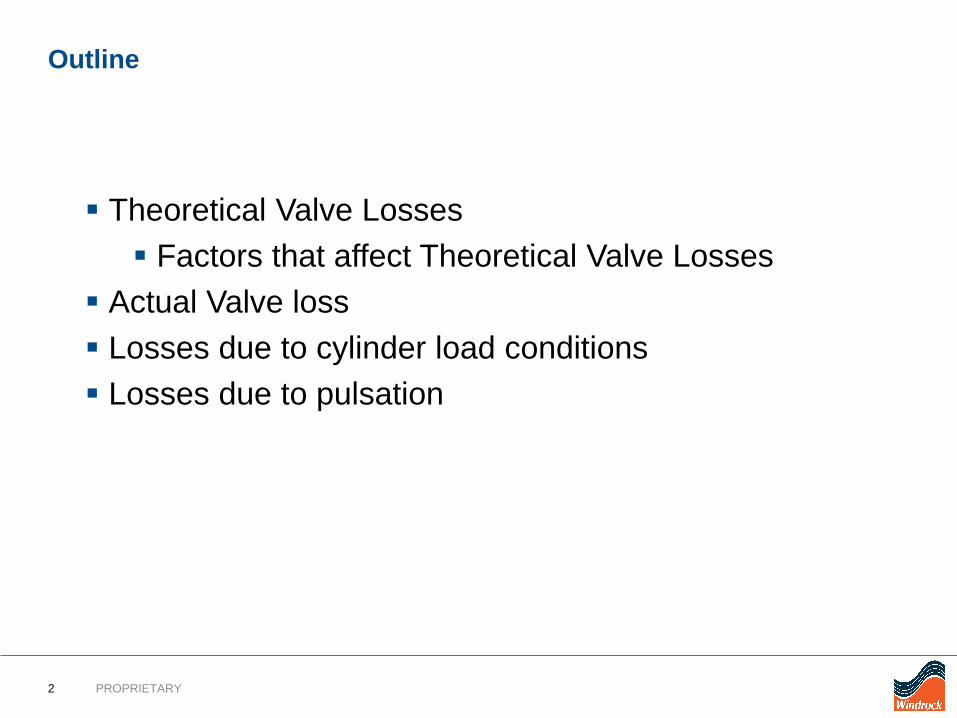
Compressor ReportValve losses
• Horsepower is how we will measure valve and piping losses
4 PROPRIETARY
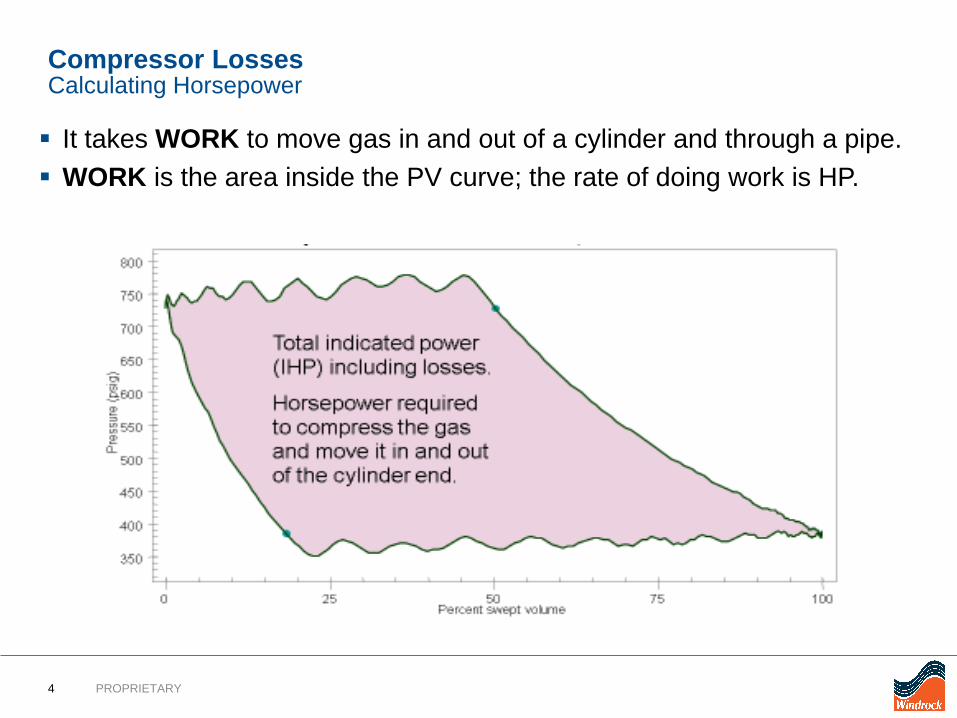
Compressor Losses
It takes WORK to move gas in and out of a cylinder and through a pipe. WORK is the area inside the PV curve; the rate of doing work is HP.
Calculating Horsepower
5 PROPRIETARY
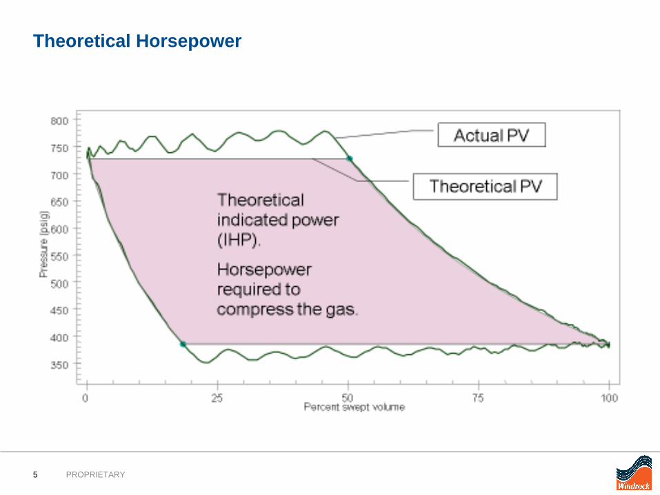
Theoretical Horsepower
6 PROPRIETARY
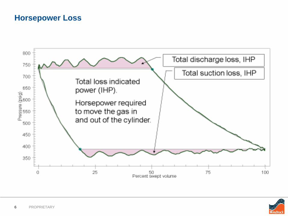
Horsepower Loss
7 PROPRIETARY
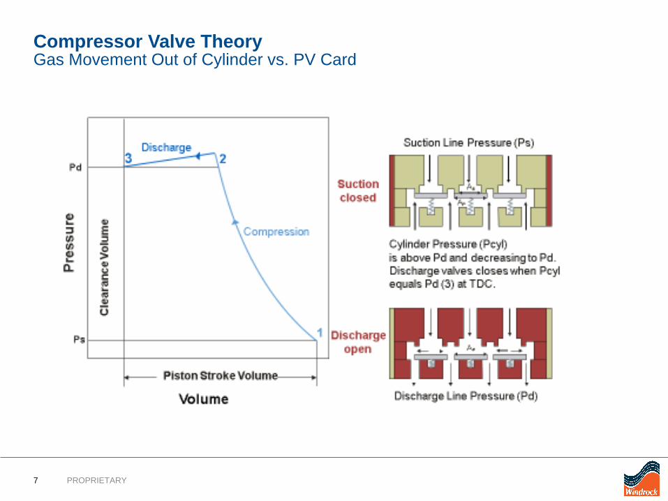
Compressor Valve TheoryGas Movement Out of Cylinder vs. PV Card
8 PROPRIETARY
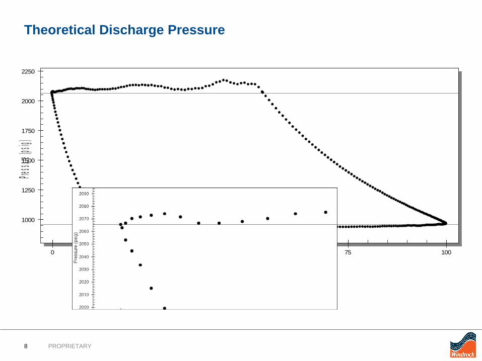
1000
1250
1500
1750
2000
2250
0 25 50 75 100
Pressure
(psig)
Percent swept volume
Theoretical Discharge Pressure
9 PROPRIETARY
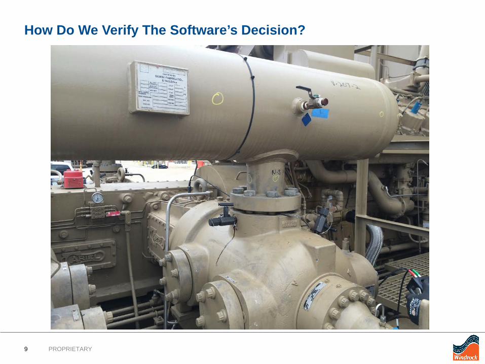
How Do We Verify The Software’s Decision?
10 PROPRIETARY
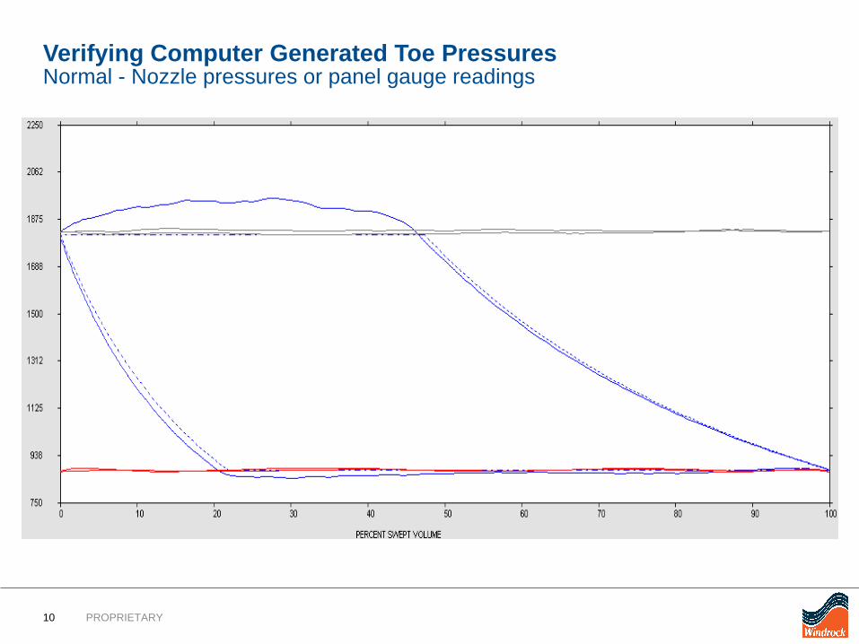
Verifying Computer Generated Toe PressuresNormal - Nozzle pressures or panel gauge readings
11 PROPRIETARY
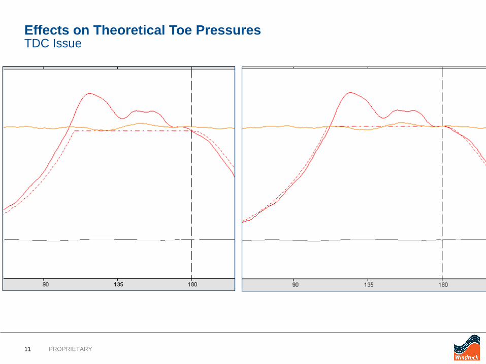
Effects on Theoretical Toe PressuresTDC Issue
12 PROPRIETARY
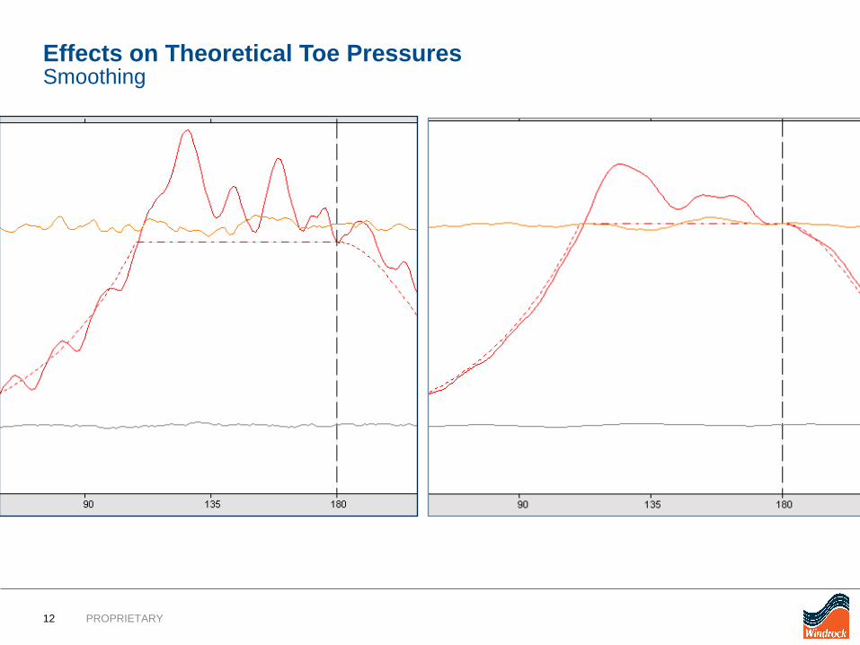
Effects on Theoretical Toe PressuresSmoothing
13 PROPRIETARY
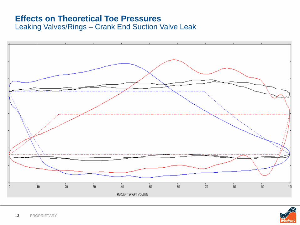
Effects on Theoretical Toe PressuresLeaking Valves/Rings – Crank End Suction Valve Leak
14 PROPRIETARY
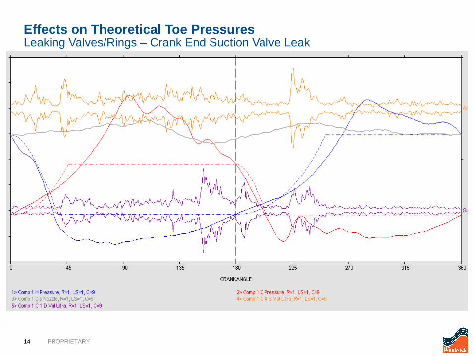
Effects on Theoretical Toe PressuresLeaking Valves/Rings – Crank End Suction Valve Leak
15 PROPRIETARY
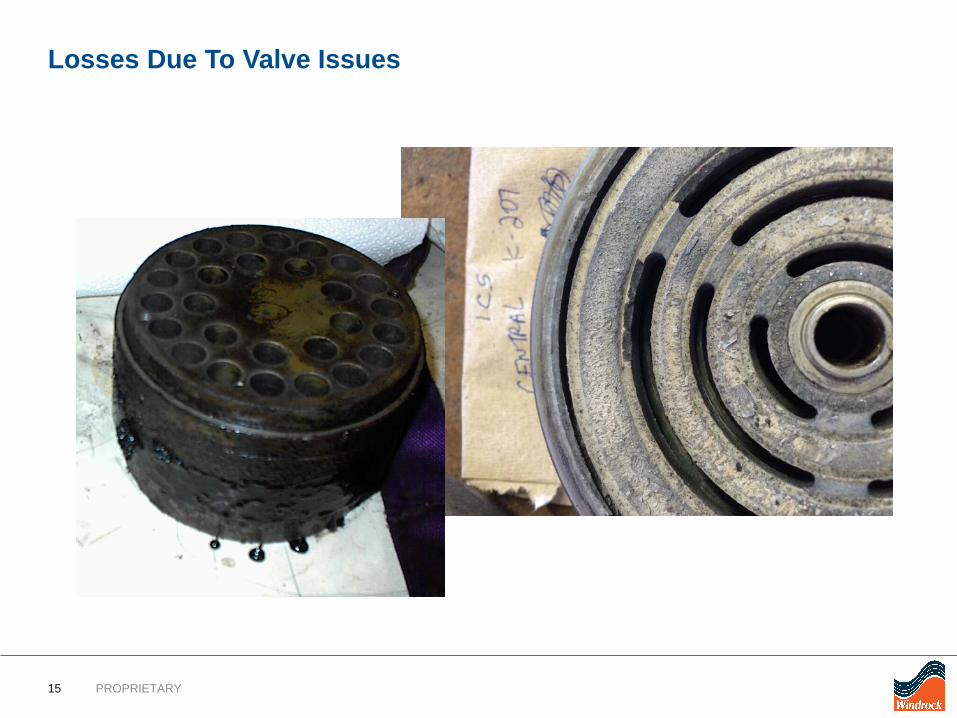
Losses Due To Valve Issues
16 PROPRIETARY
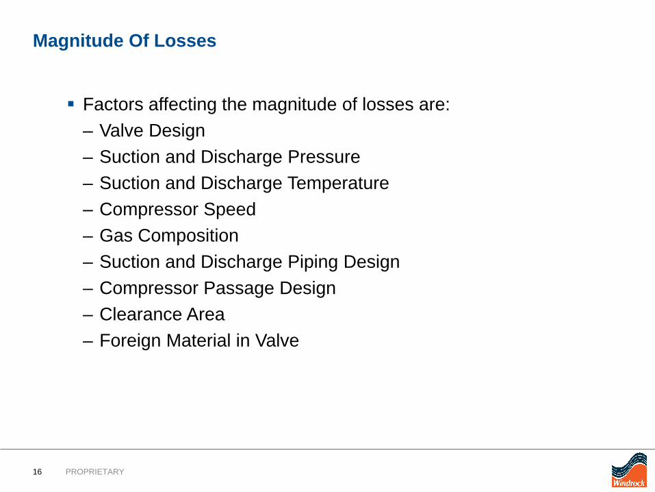
Magnitude Of Losses
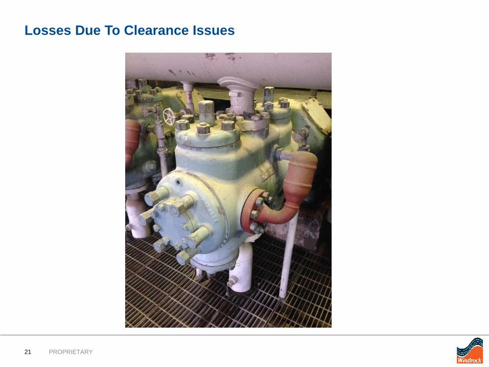
Factors affecting the magnitude of losses are:– Valve Design– Suction and Discharge Pressure– Suction and Discharge Temperature– Compressor Speed– Gas Composition– Suction and Discharge Piping Design– Compressor Passage Design– Clearance Area– Foreign Material in Valve
17 PROPRIETARY
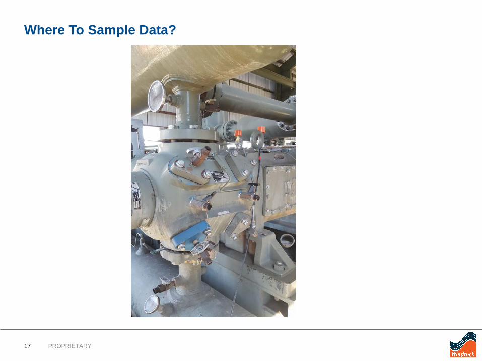
Where To Sample Data?
18 PROPRIETARY
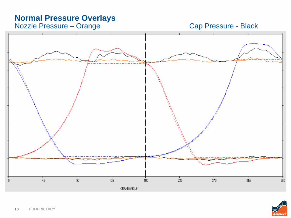
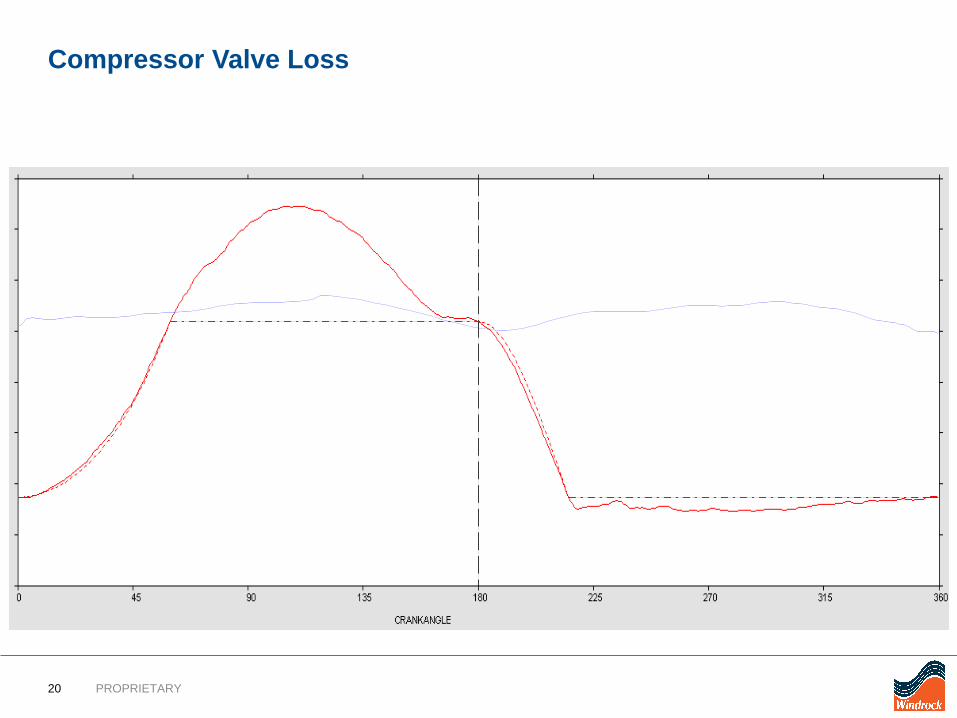
Normal Pressure OverlaysNozzle Pressure – Orange Cap Pressure - Black
19 PROPRIETARY
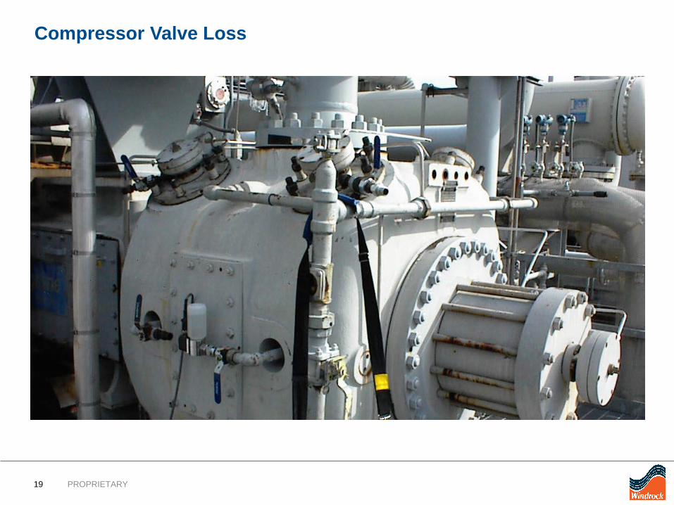
Compressor Valve Loss
20 PROPRIETARY
Compressor Valve Loss
21 PROPRIETARY
Losses Due To Clearance Issues
22 PROPRIETARY
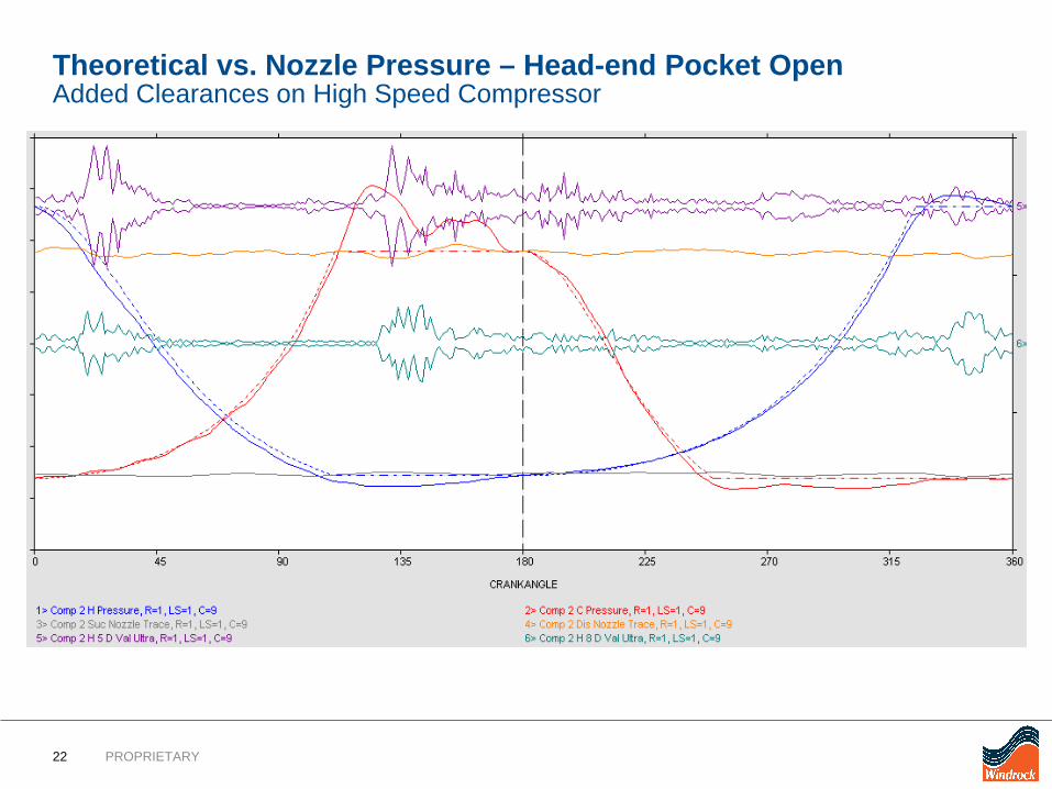
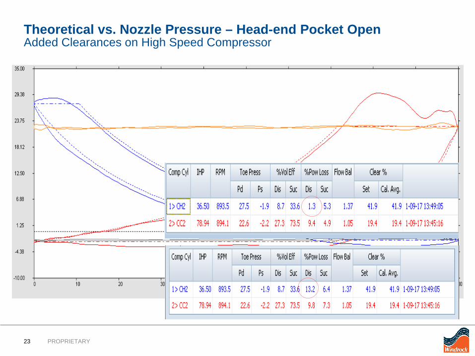
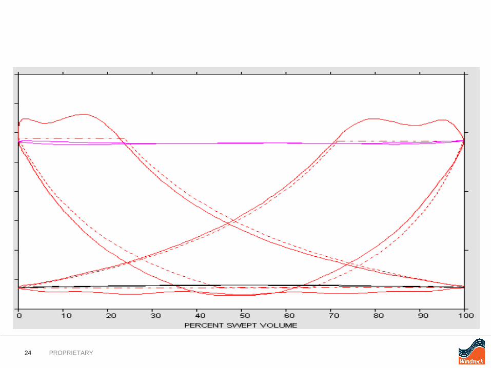
Theoretical vs. Nozzle Pressure – Head-end Pocket OpenAdded Clearances on High Speed Compressor
23 PROPRIETARY
Theoretical vs. Nozzle Pressure – Head-end Pocket OpenAdded Clearances on High Speed Compressor
24 PROPRIETARY
25 PROPRIETARY
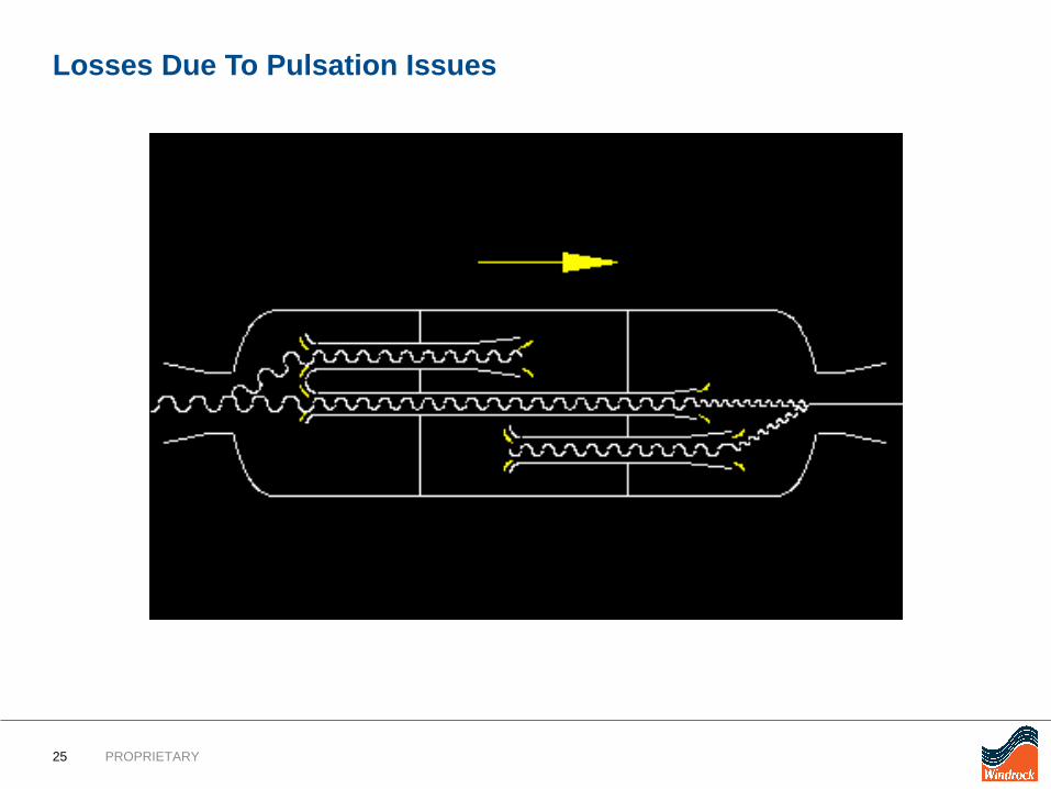
Losses Due To Pulsation Issues

26 PROPRIETARY
Pressure waves caused by the suction and discharge events in thecompressor ends Can cause vibration in piping Easier for gas to flow in through the suction than the discharge Vibration may be extreme if the pulsation coincides with:
– the acoustic resonance frequency of the piping– the mechanical natural frequency of the piping Affects compressor performance
– when valves open and close– volumetric efficiency (capacity)– HP consumed moving gas Easier for gas to flow in through the suction than the discharge
Pulsation Losses
27 PROPRIETARY
500
550
600
650
700
750
800
850
0 45 90 135 180 225 270 315 360
--------------
--------------
--------------
--------------
--------------
--------------
--------------
-----------------------------------------------------------
- Scale 2.074 DGF
- Scale 2.050 DGF
- Scale 2.076 DGF
- Scale 2.091 DGF
- Scale 2.092 DGF
- Scale 2.091 DGF
1HS3 VT1
1HS2 VT1
1HS1 VT1
1HD3 VT1
1HD2 VT1
1HD1 VT1
Pres
sure
(psi
g)
Crank Angle (deg)
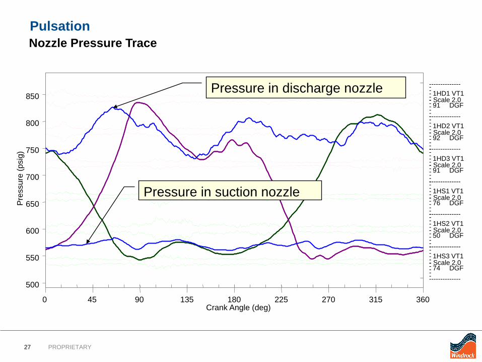
Pressure in discharge nozzle
Pressure in suction nozzle
Pulsation Nozzle Pressure Trace
28 PROPRIETARY
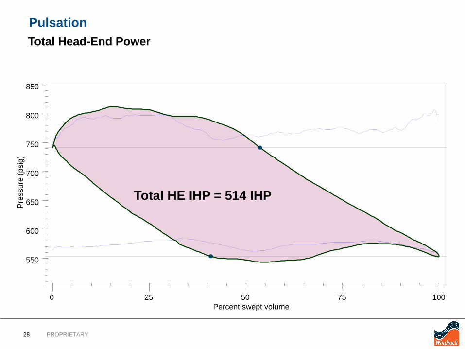
Total HE IHP = 514 IHP
550
600
650
700
750
800
850
0 25 50 75 100
Pres
sure
(psi
g)
Percent swept volume
Pulsation Total Head-End Power
29 PROPRIETARY
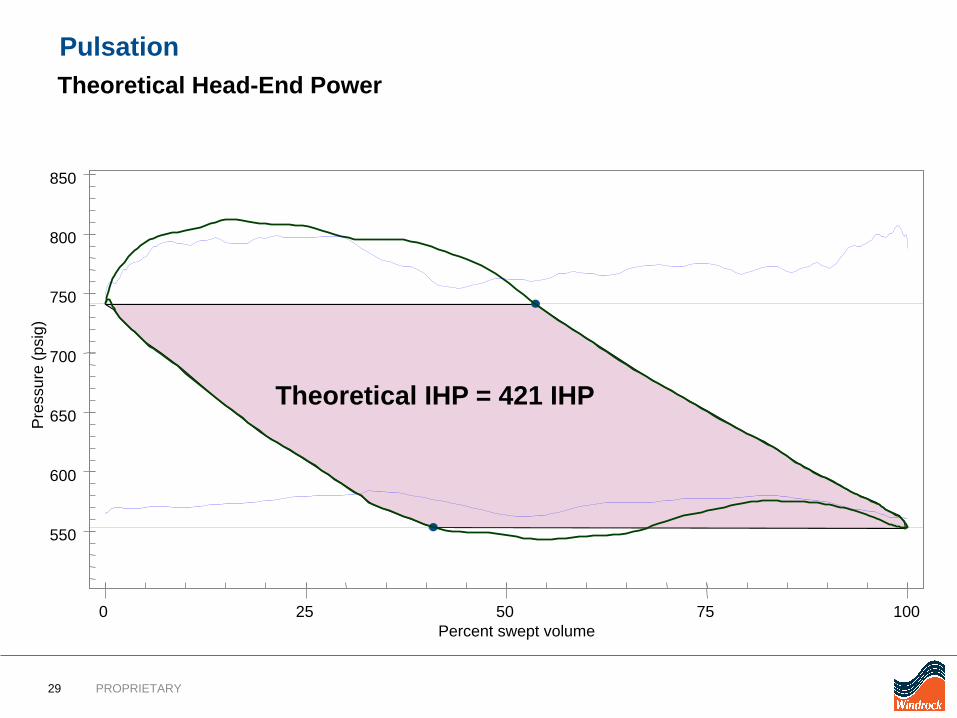
Theoretical IHP = 421 IHP
550
600
650
700
750
800
850
0 25 50 75 100
Pres
sure
(psi
g)
Percent swept volume
Pulsation Theoretical Head-End Power
30 PROPRIETARY
550
600
650
700
750
800
850
0 25 50 75 100
Pres
sure
(psi
g)
Percent swept volume
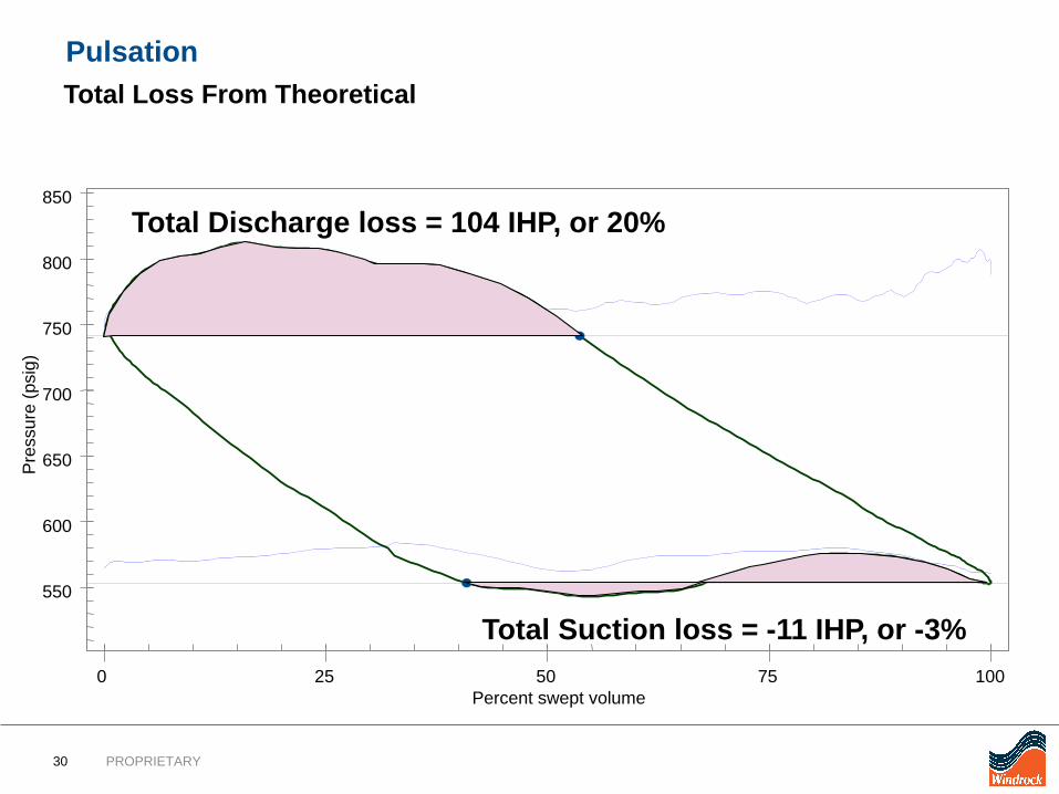
Total Discharge loss = 104 IHP, or 20%
Total Suction loss = -11 IHP, or -3%
Pulsation Total Loss From Theoretical
31 PROPRIETARY
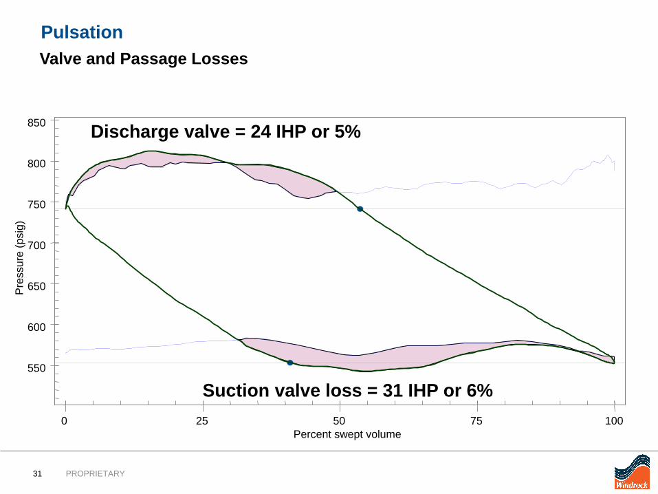
Suction valve loss = 31 IHP or 6%
Discharge valve = 24 IHP or 5%
550
600
650
700
750
800
850
0 25 50 75 100
Pres
sure
(psi
g)
Percent swept volume
Pulsation Valve and Passage Losses
32 PROPRIETARY
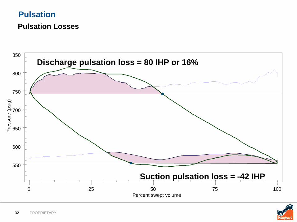
Suction pulsation loss = -42 IHP
Discharge pulsation loss = 80 IHP or 16%
550
600
650
700
750
800
850
0 25 50 75 100
Pres
sure
(psi
g)
Percent swept volume
Pulsation Pulsation Losses
33 PROPRIETARY
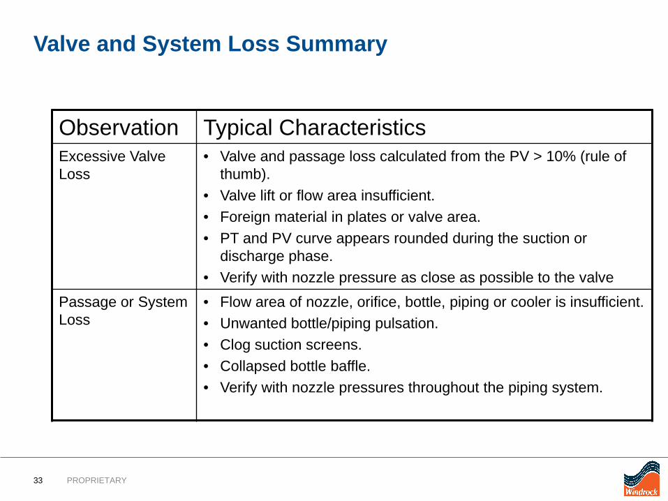
Valve and System Loss Summary
Observation Typical CharacteristicsExcessive Valve Loss
• Valve and passage loss calculated from the PV > 10% (rule ofthumb).
• Valve lift or flow area insufficient.• Foreign material in plates or valve area.• PT and PV curve appears rounded during the suction or
discharge phase.• Verify with nozzle pressure as close as possible to the valve
Passage or System Loss
• Flow area of nozzle, orifice, bottle, piping or cooler is insufficient.• Unwanted bottle/piping pulsation.• Clog suction screens.• Collapsed bottle baffle.• Verify with nozzle pressures throughout the piping system.

Thank you!