Embed Size (px)
Citation preview
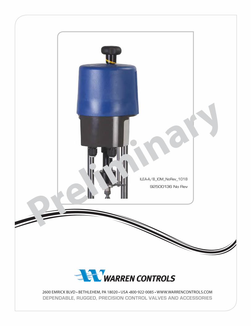
ILEA A/B Series electric actuators ILEA-Axx
ILEA-Bxx
ILEA
A/
B S
ERIE
S IO
M
ILEA-A/B_IOM_NoRev_1118
92500136 No Rev
TABLE OF CONTENTS
Function ...................................................................... 2Symbols and Safety ................................................ 2Danger Signs ............................................................. 2Usage As Per Specification ................................... 3Basic Specifications................................................. 3Operating Conditions and Installation ............ 3Removing/Closing the Cover .............................. 4Wiring Diagram ........................................................ 4High Voltage Power Supply ................................. 4Electric Supply .......................................................... 5Mount Add Pos Switches Mech/Relays ........... 5DIP Switch Functions/Settings ........................... 6
Manual Operation ................................................... 6Actuator Parts Identifications ............................. 7Actuator Removal Instruction ............................. 7Removing/Replacing of Actuator ...................... 8Operator Push Buttons .......................................... 9Operating Direction .............................................10Status Display .........................................................10Commissioning/Operation ......................... 11-12Maintenance ...........................................................12Decommissioning/Disposal ..............................12Usage and Storage ................................................13
Preliminary
Preliminary
2 2600 Emrick Blvd • Bethlehem, PA 18020 • USA • 800-922-0085 • www.warrencontrols.com
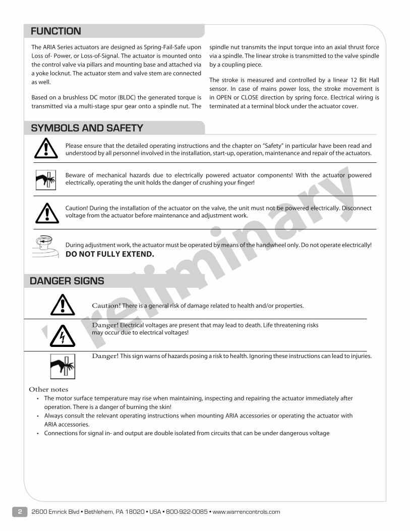
SYMBOLS AND SAFETY
Please ensure that the detailed operating instructions and the chapter on “Safety” in particular have been read and understood by all personnel involved in the installation, start-up, operation, maintenance and repair of the actuators.
Beware of mechanical hazards due to electrically powered actuator components! With the actuator powered electrically, operating the unit holds the danger of crushing your finger!
Caution! During the installation of the actuator on the valve, the unit must not be powered electrically. Disconnect voltage from the actuator before maintenance and adjustment work.
During adjustment work, the actuator must be operated by means of the handwheel only. Do not operate electrically!
DO NOT FULLY EXTEND.
FUNCTIONThe ARIA Series actuators are designed as Spring-Fail-Safe upon Loss of- Power, or Loss-of-Signal. The actuator is mounted onto the control valve via pillars and mounting base and attached via a yoke locknut. The actuator stem and valve stem are connected as well.
Based on a brushless DC motor (BLDC) the generated torque is transmitted via a multi-stage spur gear onto a spindle nut. The
spindle nut transmits the input torque into an axial thrust force via a spindle. The linear stroke is transmitted to the valve spindle by a coupling piece.
The stroke is measured and controlled by a linear 12 Bit Hall sensor. In case of mains power loss, the stroke movement is in OPEN or CLOSE direction by spring force. Electrical wiring is terminated at a terminal block under the actuator cover.
DANGER SIGNS
Caution! There is a general risk of damage related to health and/or properties.
Danger! Electrical voltages are present that may lead to death. Life threatening risks may occur due to electrical voltages!
Danger! This sign warns of hazards posing a risk to health. Ignoring these instructions can lead to injuries.
Other notes• The motor surface temperature may rise when maintaining, inspecting and repairing the actuator immediately after
operation. There is a danger of burning the skin!• Always consult the relevant operating instructions when mounting ARIA accessories or operating the actuator with
ARIA accessories.• Connections for signal in- and output are double isolated from circuits that can be under dangerous voltage
Preliminary
3 ILEA-A/B_IOM_NoRev_1118
USAGE AS PER SPECIFICATION• ARIA Series actuators are exclusively designed to be used as
electric valve actuators for rising stem globe control valves. They are meant to be mounted on Warren Controls, control valves in order to run their motors.
• Any other use is considered to be non-compliant and the manufacturer cannot be held liable for any damage resulting from it.
• The actuators can only be used within the limits laid out in the data sheets, catalogues and other documents. Otherwise, the manufacturer cannot be held liable for any resulting damage.
• Usage as per specification includes the observance of the operating, service and maintenance conditions laid down by the manufacturer.
• Read this document in its entirety as special precautions need to be taken before mounting and adjusting the actuator as well as servicing!
• The actuators may only be used, serviced and repaired by personnel that is familiar with them and informed about potential hazards. The specific regulations for the prevention of accidents have to be observed.
• Damages caused by unauthorized modifications carried out on the actuators are excluded from the manufacturer’s liability.
• Supply voltage may only be switched on after the proper closure of the main cover or terminal box.
ILEA SERIES BASIC SPECIFICATIONS
Spring-FailARIA
Stroke Speed 12 Secs/In., (2 mm/sec.), Fixed. Spring-Fail Speed: 2.3 mm/sec.
What happens under the condition of Loss of Power, under voltage or over voltage. Actuator engages Spring Fail, to Open or Close, Depending on model.
What happens under the condition of Loss of Control Signal.
Actuator engages Spring Fail, to Open or Close, Depending on model. With control by binary inputs, actuator stops in position when event occurs.
MAX Thrust: 455 Lbf (2kN)MAX Stroke: 1.38 In. (35mm)
Manual Override (electric): via 2 push buttons when poweredPower Supply: 24 VAC/DC, optionally wide range PS (100-240 VAC)
Motor protection: Electronic motor current monitoring with safety cut-offDuty cycle as per IEC 60034-1,8: S2 30 min/ S4 1200c/h-50% ED
Permitted ambient temperature: -4ºF to 140ºF (-20ºC to +60ºC)Internal fault monitoring: Thrust, Control Signal, Temperature, Power Supply
Binary control: 24-230- VAC for ON/OFF serviceControl Signal and Feedback: 0-20 mA, 4-20 mA, 0-10 V, 2-10 V selectable, plus split range
Mounting Position: Any position, except cover pointing downwardsConduit entries: 2 pcs. M 20 x 1.5 /1 pc. M 16 x15
Enclosure Rating. to EN 60529: IP67Fuse - HV Power Supply: 2 AMP, 5 x 20 mm, 250 VAC, Slow Blow
POWER CONSUMPTION25 WATTS, MAX CURRENT1.8 A at 24 VAC / DC
0.36 A at 115 VAC
0.18 A at 230 VAC
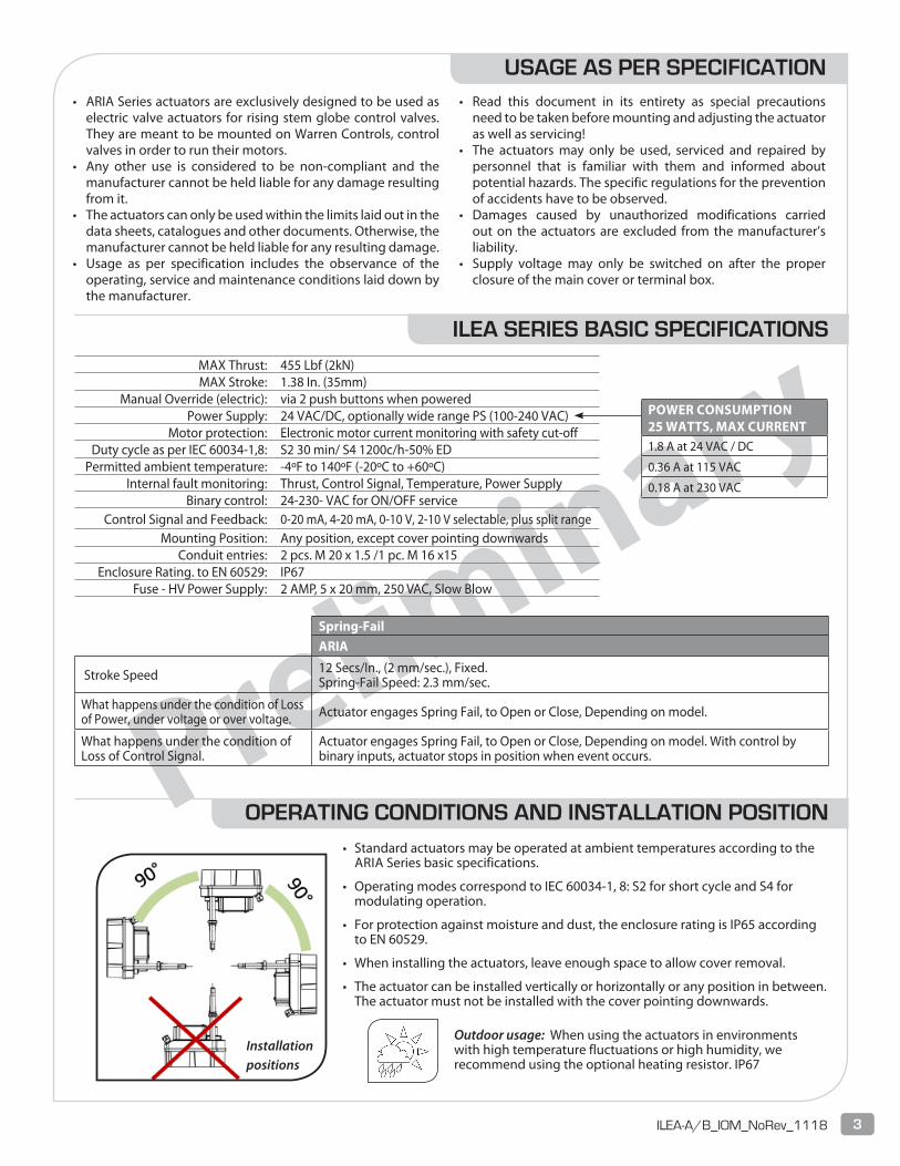
OPERATING CONDITIONS AND INSTALLATION POSITION• Standard actuators may be operated at ambient temperatures according to the
ARIA Series basic specifications.
• Operating modes correspond to IEC 60034-1, 8: S2 for short cycle and S4 for modulating operation.
• For protection against moisture and dust, the enclosure rating is IP65 according to EN 60529.
• When installing the actuators, leave enough space to allow cover removal.
• The actuator can be installed vertically or horizontally or any position in between. The actuator must not be installed with the cover pointing downwards.
Outdoor usage: When using the actuators in environments with high temperature fluctuations or high humidity, we recommend using the optional heating resistor. IP67
Installation positions
Preliminary
4 2600 Emrick Blvd • Bethlehem, PA 18020 • USA • 800-922-0085 • www.warrencontrols.com
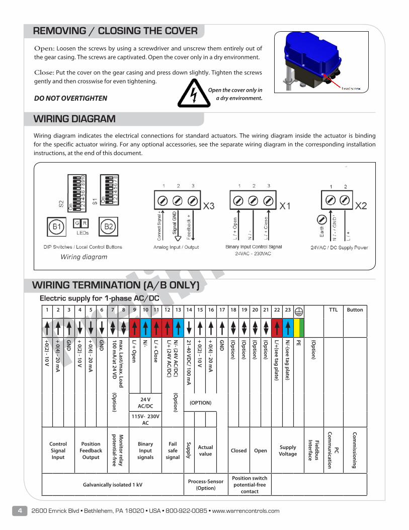
WIRING TERMINATION (A/B ONLY)
1 2 3 4 5 6 7 8 9 10 11 12 13 14 15 16 17 18 19 20 21 22 23 TTL Button
+0(2) - 10 V
+ 0(4) - 20 mA
GN
D
+ 0(2) - 10 V
+ 0(4) - 20 mA
GN
D
max. Last/m
ax. Load 100 m
A/at 24 VD
(Option)
L/ + Open
N/-
L/ + Close
N/- (24V A
C/DC) (O
ption)L/+ (24V A
C/DC)
21-40 VDC/ 100 m
A
+ 0(2) - 10 V
+ 0(4) - 20 mA
GN
D
(Option)
(Option)
(Option)
(Option)
L/+(see tag plate)
N/-(see tag plate)
PE (Option)
24 VAC/DC
(OPTION)
115V- 230V AC
Control SignalInput
Position Feedback
Output
Monitor relay
potential-free
Binary Input
signals
Fail safe
signal
Supply
Actual value
Closed OpenSupply Voltage
Fieldbus Interface
PC Com
munication
Comm
issioning
Galvanically isolated 1 kVProcess-Sensor
(Option)
Position switchpotential-free
contact
Electric supply for 1-phase AC/DC
REMOVING / CLOSING THE COVER
Open: Loosen the screws by using a screwdriver and unscrew them entirely out of the gear casing. The screws are captivated. Open the cover only in a dry environment.
Close: Put the cover on the gear casing and press down slightly. Tighten the screws gently and then crosswise for even tightening.
DO NOT OVERTIGHTENOpen the cover only in
a dry environment.
Wiring diagram indicates the electrical connections for standard actuators. The wiring diagram inside the actuator is binding for the specific actuator wiring. For any optional accessories, see the separate wiring diagram in the corresponding installation instructions, at the end of this document.
WIRING DIAGRAM
Preliminary
5 ILEA-A/B_IOM_NoRev_1118
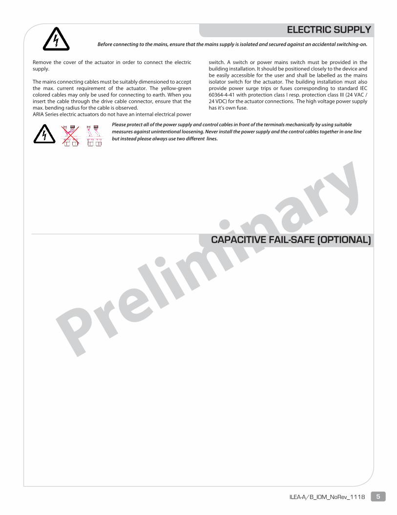
ELECTRIC SUPPLYBefore connecting to the mains, ensure that the mains supply is isolated and secured against an accidental switching-on.
Please protect all of the power supply and control cables in front of the terminals mechanically by using suitable measures against unintentional loosening. Never install the power supply and the control cables together in one line but instead please always use two different lines.
Remove the cover of the actuator in order to connect the electric supply.
The mains connecting cables must be suitably dimensioned to accept the max. current requirement of the actuator. The yellow-green colored cables may only be used for connecting to earth. When you insert the cable through the drive cable connector, ensure that the max. bending radius for the cable is observed.ARIA Series electric actuators do not have an internal electrical power
switch. A switch or power mains switch must be provided in the building installation. It should be positioned closely to the device and be easily accessible for the user and shall be labelled as the mains isolator switch for the actuator. The building installation must also provide power surge trips or fuses corresponding to standard IEC 60364-4-41 with protection class I resp. protection class III (24 VAC / 24 VDC) for the actuator connections. The high voltage power supply has it’s own fuse.
CAPACITIVE FAIL-SAFE (OPTIONAL)
Preliminary
6 2600 Emrick Blvd • Bethlehem, PA 18020 • USA • 800-922-0085 • www.warrencontrols.com
POSITION SWITCH SET UP (OPTIONAL)
FAULT RELAY DESCRIPTION

Preliminary
7 ILEA-A/B_IOM_NoRev_1118
DEFAULT PARAMETERS
SOFTWARE SET UP
Preliminary
8 2600 Emrick Blvd • Bethlehem, PA 18020 • USA • 800-922-0085 • www.warrencontrols.com
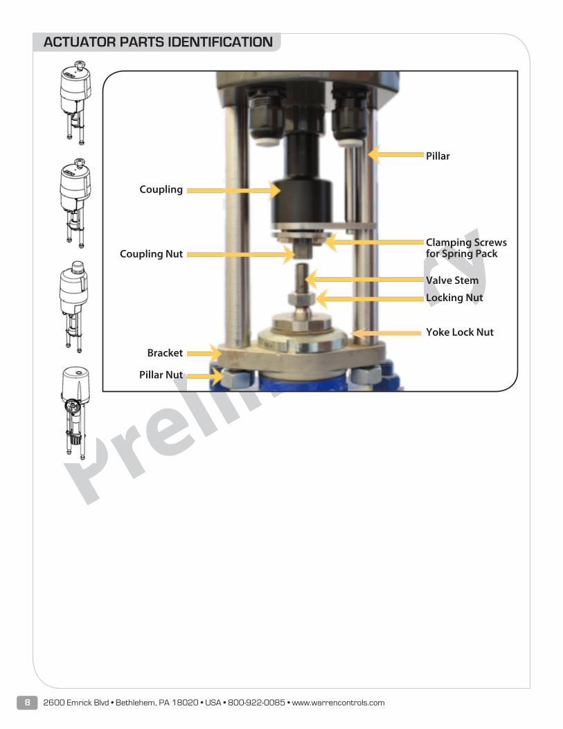
ACTUATOR PARTS IDENTIFICATION
Pillar
Clamping Screws for Spring Pack
Valve Stem
Locking Nut
Yoke Lock Nut
Coupling
Coupling Nut
Bracket
Pillar Nut

Preliminary
9 ILEA-A/B_IOM_NoRev_1118
ACTUATOR REMOVAL/REPLACEMENT INSTRUCTIONS
Preliminary
10 2600 Emrick Blvd • Bethlehem, PA 18020 • USA • 800-922-0085 • www.warrencontrols.com
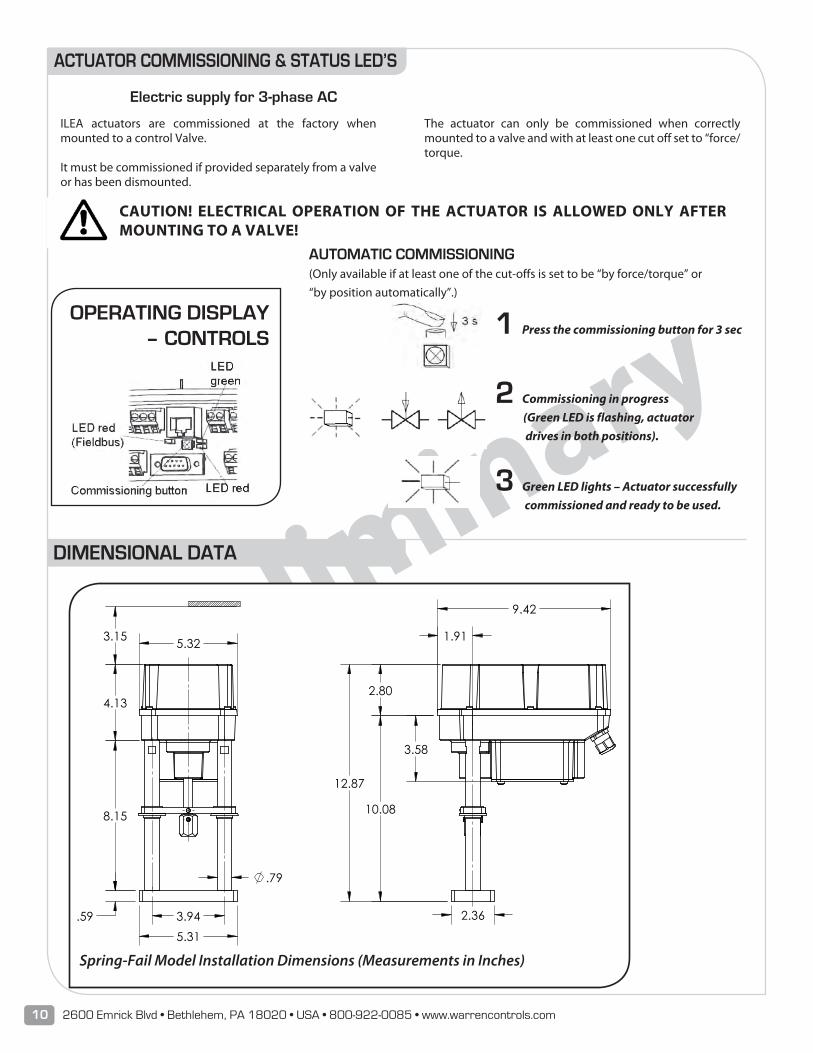
DIMENSIONAL DATA
3.15
PSF-402
10.08
1.91
9.42
12.87
3.58
2.80
2.36
5.32
8.15
5.31 3.94
4.13
.59
.79
Spring-Fail Model Installation Dimensions (Measurements in Inches)
ACTUATOR COMMISSIONING & STATUS LED’S
Electric supply for 3-phase AC
CAUTION! ELECTRICAL OPERATION OF THE ACTUATOR IS ALLOWED ONLY AFTER MOUNTING TO A VALVE!
AUTOMATIC COMMISSIONING(Only available if at least one of the cut-offs is set to be “by force/torque” or “by position automatically”.)
1 Press the commissioning button for 3 sec
2 Commissioning in progress (Green LED is flashing, actuator drives in both positions).
3 Green LED lights – Actuator successfully commissioned and ready to be used.
OPERATING DISPLAY – CONTROLS
ILEA actuators are commissioned at the factory when mounted to a control Valve. It must be commissioned if provided separately from a valve or has been dismounted.
The actuator can only be commissioned when correctly mounted to a valve and with at least one cut off set to “force/torque.

Preliminary
11 ILEA-A/B_IOM_NoRev_1118
Preliminary
12 2600 Emrick Blvd • Bethlehem, PA 18020 • USA • 800-922-0085 • www.warrencontrols.com
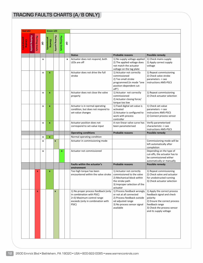
TRACING FAULTS CHARTS (A/B ONLY)
21
18. Tracing faults Red LED Green LED
Glowing
permanently
Flashing quickly
Flashing slowly
Off
Glowing
permanently
Flashing quickly
Flashing slowly
Off
Status Probable reasons Possible remedy x x Actuator does not respond, both
LEDs are off 1) No supply voltage applied 2) The applied voltage does not match the actuator voltage on the tag plate
1) Check mains supply 2) Apply correct supply voltage
x x Actuator does not drive the full stroke
1) Actuator not correctly commissioned 2) Too small stroke programmed (in mode “one position‐dependent cut‐off”)
1) Repeat commissioning 2) Check valve stroke parameters ‐> see instructions AMS‐PSCS
x x Actuator does not close the valve properly
1) Actuator not correctly commissioned 2) Actuator closing force/ torque too low
1) Repeat commissioning 2) Check actuator selection
x x Actuator is in normal operating condition, but does not respond to set‐value changes
1) Fixed digital set‐value is activated 2) Actuator is configured to work with process controller
1) Check set‐value parameters ‐> see instrucions AMS‐PSCS 2) Connect process sensor
x x Actuator position does not correspond to set‐value input
A non‐linear valve curve has been parameterised
Verify parameterised characteristic ‐> see instructions AMS‐PSCS
Operating conditions Probable reasons Possible remedy x x Normal operating condition x x
Actuator in commissioning mode Commissioning mode will be
left automatically after completion
x x Actuator not commissioned Depending on the type of cut‐offs, the actuator has to be commissioned either automatically or manually
Faults within the actuator’s environment
Probable reasons Possible remedy
x x Too high torque has been encountered within the valve stroke
1) Actuator not correctly commissioned to the valve 2) Mechanical block within the stroke path 3) Improper selection of the actuator
1) Repeat commissioning 2) Check valve and actuator for unobstructed running 3) Check actuator selection
x x
1) No proper process feedback (only in combination with PSIC) 2+3) Maximum control range exceeds (only in combination with PSIC)
1) Process feedback wrongly or not at all connected 2) Process feedback outside od adjusted range 3) No process sensor signal available
1) Apply the correct process feedback signal and check polarity 2) Ensure the correct process feedback range 3) Check the process sensor and its supply voltage
Preliminary
13 ILEA-A/B_IOM_NoRev_1118
22
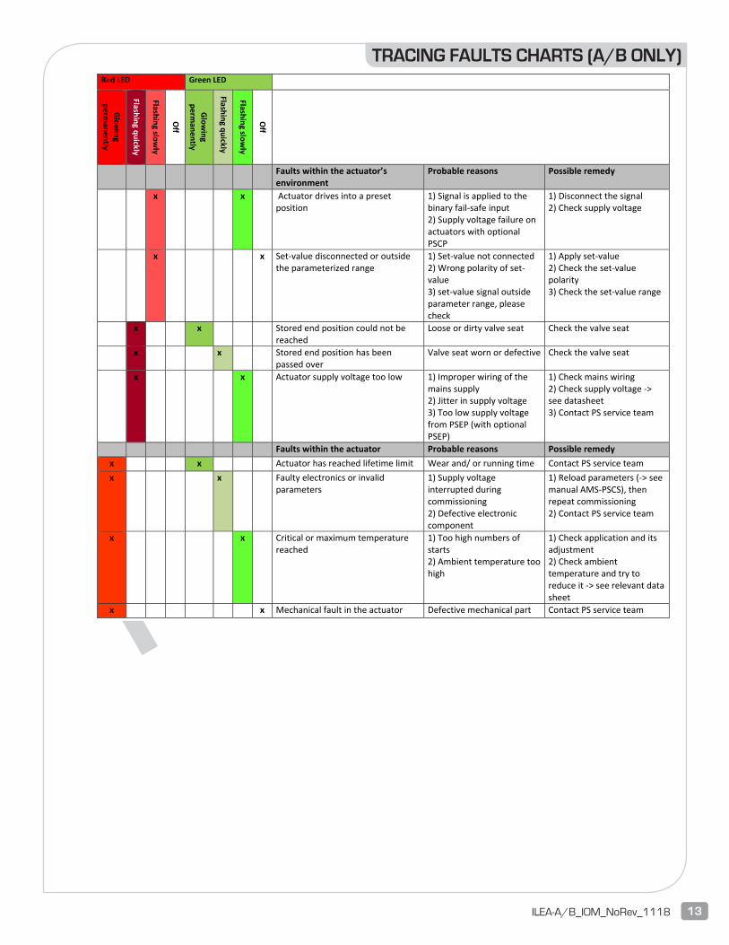
Red LED Green LED
Glowing
permanently
Flashing quickly
Flashing slowly
Off
Glowing
permanently
Flashing quickly
Flashing slowly
Off
Faults within the actuator’s environment
Probable reasons Possible remedy
x x Actuator drives into a preset position
1) Signal is applied to the binary fail‐safe input 2) Supply voltage failure on actuators with optional PSCP
1) Disconnect the signal 2) Check supply voltage
x x Set‐value disconnected or outside the parameterized range
1) Set‐value not connected 2) Wrong polarity of set‐value 3) set‐value signal outside parameter range, please check
1) Apply set‐value 2) Check the set‐value polarity 3) Check the set‐value range
x x Stored end position could not be reached
Loose or dirty valve seat Check the valve seat
x x
Stored end position has been passed over
Valve seat worn or defective Check the valve seat
x x Actuator supply voltage too low 1) Improper wiring of the mains supply 2) Jitter in supply voltage 3) Too low supply voltage from PSEP (with optional PSEP)
1) Check mains wiring 2) Check supply voltage ‐> see datasheet 3) Contact PS service team
Faults within the actuator Probable reasons Possible remedy x x Actuator has reached lifetime limit Wear and/ or running time Contact PS service team x x
Faulty electronics or invalid
parameters 1) Supply voltage interrupted during commissioning 2) Defective electronic component
1) Reload parameters (‐> see manual AMS‐PSCS), then repeat commissioning 2) Contact PS service team
x x Critical or maximum temperature reached
1) Too high numbers of starts 2) Ambient temperature too high
1) Check application and its adjustment 2) Check ambient temperature and try to reduce it ‐> see relevant data sheet
x x Mechanical fault in the actuator Defective mechanical part Contact PS service team
TRACING FAULTS CHARTS (A/B ONLY)

Preliminary
14 2600 Emrick Blvd • Bethlehem, PA 18020 • USA • 800-922-0085 • www.warrencontrols.com

Preliminary
15 ILEA-A/B_IOM_NoRev_1118
2600 EMRICK BLVD • BETHLEHEM, PA 18020 • USA •800-922-0085 • WWW.WARRENCONTROLS.COMDEPENDABLE, RUGGED, PRECISION CONTROL VALVES AND ACCESSORIES
ILEA-A/B_IOM_NoRev_1018
92500136 No Rev
Preliminary