Embed Size (px)
Citation preview
IMACS, the multi-object spectrograph and imager forMagellan: a status report
Bruce C. Bigelow and Alan Dressler
Observatories of the Carnegie Institution of Washington,813 Santa Barbara St., Pasadena, CA 91101
ABSTRACT
The Inamori Magellan Areal Camera and Spectrograph (IMACS) will soon be one of thethree first-generation instruments for the Magellan 6.5m telescopes. This instrumentdrove the specification and design of the f/11 Gregorian focus on Magellan, which it usesto feed an all-spherical, refracting wide-field collimator with a 30 arcmin field of view.Two Epps cameras are used to re-image the field of view for imaging and spectroscopy.The aspheric, f/2 (“short”) camera images a field of 27 x 27 arcmin at 0.2 arcsec/pixel,and produces 0.32 arcsec images averaged over all field positions across the 0.39 –1.05micron bandpass. The all-spherical f/4 (“long”) camera images a field 15 x 15 arcmin at0.11 arcsec/pixel, and produces 0.16 arcsec images averaged over all field positionsacross the 0.365 – 1.0 micron bandpass. This paper describes the final specificationsfor the multiple spectrographic and imaging modes, and provides a status report on thecurrent state of the instrument project.
Keywords: MOS, spectrographs, optics, cameras, opto-mechanics, flexure control,
1. INTRODUCTION
The IMACS (Inamori Magellan Areal Camera and Spectrograph) is the principal multi-object spectrographand imager for the 6.5m Magellan I telescope. The five year, five million dollar project to build theinstrument is in its final stages at the instrument laboratories of the Carnegie Observatories in Pasadena,Ca. This paper provides a status report for the instrument, and describes some of its features. Seeadditional papers in these proceedings by Dressler1 (target science for IMACS), Epps2 (the opticallyathermalized f/2 camera), Bigelow3 ( the CCD detector and dewar system), and Sutin4 (echellette mode).Concurrently, the Observatories are in the final stages of construction for the telescopes and the firstgeneration of optical and infrared instrumentation. See Shectman5 for report about telescope projectprogress, and Bernstein6 for a description of the MIKE double-echelle spectrograph.
IMACS mounts at the Nasmyth focus of the Magellan I telescope. Fed by the f/11 Gregorian configuration(which will soon include an integral ADC and field corrector mounted at the tertiary mirror), thetransmitting, all-spherical collimator produces a well corrected, unvignetted field of 24 arcmin in diameter,and a full 30 arcmin in diameter with slight vignetting. Two cameras are used to re-image the 150mm-diameter collimator exit pupil at 0.111 and 0.201 arcsec/pixel. The all-spherical, f/4 Epps “long” cameracan directly image a 15 x 15 arcmin field of view (FOV), or spectroscopically image a 15 arcmin long slitwith a variety of standard 150 x 200 mm diffraction gratings. The aspheric, f/2 Epps “short” camera candirectly image a 27 x 27 arcmin FOV (with slight vignetting), or spectroscopically image a 27 arcmin longslit with a variety of 150mm-aperture grisms. Both cameras feed a single 8192 x 8192 CCD mosaic. Ageneral summary of the instrument specifications is shown in Table 1.
2. SPECIFICATIONS
IMACS images with two optical systems which can operate in either imaging or spectrographic modes.The specifications for each camera are shown in table 1.
Feature F/4 “Long” Camera F/2 “Short” CameraFocal length 641.8 mm 355.6 mmFocal ratio f/4.3(imaging), f/2.66 (anamorphic) f/2.38 (imaging), f/1.47 (ana.)Field of view 15.46 arcmin X 15.46 arcmin 27.2 arcmin X 27.2 arcminVignetting None None below 24 arcmin radiusTotal area 239 square arcmin 635 square arcminPixel scale 9.0 pixels/arcsec 5.0 pixels/arcsecDesign wavelength range 0.365 – 1.0 microns 0.390 – 1.05 micronsAllow wavelength range 0.330 – 1.1 microns 0.390 – 1.1 microns
Table 1. IMACS camera specifications.
Spectroscopy with the long camera uses reflection gratings. Table 2 shows the current selection of gratingsand their operating parameters.
Ruling Blaze angle Order Wavelength range Dispersion DispersionLines/mm Degrees Microns R/0.5 arcsec slit Angstroms/pixel
300 4.3 1 0.365-0.974 2162 0.743600 8.63 1 0.365-0.675 3491 0.378600 13.0 1 0.684-1.000 6117 0.387
1200 17.45 1 0.365-0.523 6542 0.1941200 26.7 1 0.846-1.000 20693 0.1881200 26.7 2 0.365-0.443 15740 0.0961200 26.7 2 0.482-0.557 28082 0.092
Table 2. Gratings and dispersions.
Spectroscopy with the short camera is accomplished with grisms. Table 3 shows the current selection ofgrisms and their operating parameters.
Ruling Blaze angle Order Central Wavelength DispersionLines/mm Degrees Microns Angstroms/pixel
200 15 1 0.66 2.037300 17.5 1 0.67 1.341600 34.0 1 0.77 0.583
Table 3. Grisms and dispersions.
In general, the image quality target for both cameras is to limit image motion (flexure) to 0.1 pixel fortypical 1-hour exposures. This specification places tight constraints on tilts and deflections of all of theinstrument optical components and support structures. Detailed error budgets for static (alignment) anddynamic (exposure) image quality have been used to direct the design of the opto-mechanical systems.
3. OPTICAL SYSTEM
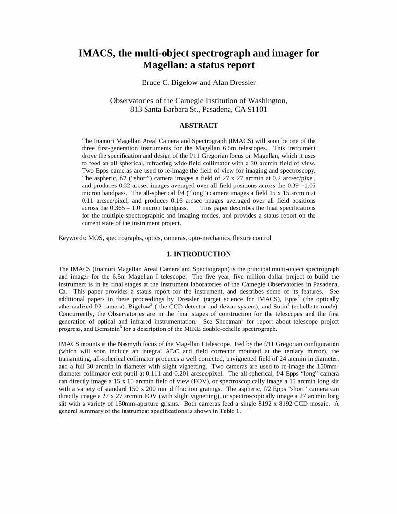
There are four main lens groups in the IMACS optical system, and these are shown in figure 1. Fromtelescope focus to science array focus, the groups include a singlet field lens, a four-element, all-sphericalrefracting collimator, a six element, all refracting “long” camera, and an 8-element aspheric “short”camera. Not shown in the figure are the pupil elements, which include imaging mirrors, gratings, and
grisms, which are installed at the intersection of the main and long camera optical axes. The originalconcept for the field lens and collimator were developed by Shectman [7], and the final designs for thecollimator and both cameras were designed by Harland Epps [2,8].
���������� ����� �
���������
��� ������
Figure 1. Schematic of the IMACS main optical systems
3.1 Field Lens
The field lens is a singlet fused silica lens, 650 mm in diameter, which weighs 34 Kg. The lens blank wasprovided by Dynasil (West Berlin, NJ), at an approximate cost of $14,220. Brashears LP (Pittsburgh, PA)polished the lens, at an approximate cost of $55,870. Finally, the polished optic was sol-gel coated byCleveland Crystals Inc (Highland Heights, OH) for approximately $34,770, which included tooling andshipping fixtures.
3.2 Collimator
The collimator consists of four lenses in three groups (two singlets and a doublet), as shown in Figure 1.The materials, in order of occurrence in the optical path, are Dynasil 1100 fused silica, Ohara S-FSL5Y(Rancho Santa Margarita, CA), Ohara BSM51Y, and Optovac (North Brookfield, MA) calcium fluoride(CaF2). Note that the optical glasses were selected from the Ohara I-Line catalog for high transmission inthe near ultra-violet (UV). The total glass and crystal cost for the collimator was about $55,000. TucsonOptical Research Corp. (Tucson, AZ) polished the lenses at a cost of about $26,180. Following polishing,the three glass lenses were sent to Newport Thin Films Labs (NTFL, Chino, CA) for anti-reflection (AR)coating. Ultimately, elements C02 and C03 were coated by NTFL, while C04 and C05 were later coatedby Spectrum Thin Films Labs (STFL, Knickerbocker, NY), with a total coating cost of about $23,500 forsix surfaces. The collimator doublet was coupled with Cargille 5610 laser liquid (Cargille Labs, CedarGrove, NJ).

3.3 F/4 Camera
The f/4 camera uses six lenses in four groups (singlet-triplet-singlet-singlet). The materials, from entranceto focus, are Ohara FPL51Y, Ohara BAL15Y, Optovac CaF2, Ohara S-LAL7, CaF2, and BSM51Y. Notethat, as in the collimator, all optical glasses are from the Ohara I-line catalog, and were selected for hightransmission in the near ultra-violet. The approximate total cost of the long camera lens materials was$87,500. After polishing by TORC, at cost of $39,000, all of the lenses except L03 were sent to STFL forAR coating, at a cost of $33,300. L03 is embedded in a triplet, and is coupled to its neighbors with Cargille5610 laser liquid.
3.4 F/2 Camera
The f/2 camera uses eight lenses in four groups (doublet-singlet-quartet-singlet). The materials are S-LAL7, CaF2, CaF2, BSM51Y, CaF2, BSM51Y, S-FPL51Y, and S-LAL7 with the same material suppliersas in the collimator and long camera. Total cost of the optical glasses and CaF2 crystals was $183,250.Two of the short camera lenses have aspheres on one side – elements 1 and 7. Tinsley Optical Labs(Richmond, CA) polished the aspheric lenses, at a cost of $133,000 (for two lenses). The remaining lenseswere polished by TORC, at a cost of $39,000, and AR coatings were again provided by STF for $52,750 (8surfaces). One interesting feature of the short camera design is the focus and scale athermalization isprovided by “oil lenses” formed by the elements in the quartet and the oil couplant. See Epps[2] in theseproceedings for a full description of the short camera optical design and optical athermalization.
3.5 Diffraction Gratings, Grisms, and Miscellaneous Optics
The gratings in Table 2 were purchased from Thermo/RGL (Rochester, NY). Brian Sutin designed thegrisms. The grism materials for the 15º, 17.5º, and 34º grisms are Ohara BSL7Y, S-LAL12, and PBH53Wrespectively. The prisms are being cut and polished by Harold Johnson Optical Labs (Gardena, CA) , andThermo/RGL will apply the rulings. The remaining optics include two imaging mirrors, one aluminizedand one silver coated. The mirrors were polished and coated by Custom Scientific (Phoenix, AZ). Theguide camera optical systems were designed by Brian Sutin, and use Canon (Lake Success, NY), EdmundIndustrial Optics (Barrington, NJ), and Adaptive Optics Associates (Boston, MA) components.
As of late July, 2002, all of the optics are polished, coated, and mounted, except for the short cameralenses, the last of which (aspheres) are due at the end of July, and the grisms, all of which are in variousstages of prism cutting and polishing.
4. DETECTOR SYSTEMS
IMACS uses two locally designed detector controller systems; one design for the Magellan guide cameras,and a second, related design for the science mosaic. Both systems were designed by Greg Burley and IanThompson of OCIW. The guide camera detectors are EEV CCD47-20 devices, and the science detectorsare SITe ST002AB1-0 devices. Only the guide cameras are discussed here. See Bigelow1 in theseproceedings for details and status of the dewar and detector systems.
4.1 Guide Cameras
The Magellan guider camera design was developed to be used in a number of instruments, as part of theNasmyth guider system, and as part of the telescope active optics system. In operation, the guide camerassupport a full-frame imaging mode, a fast sub-raster imaging/centroiding mode for rapid guiding, and aShack-Hartmann wavefront-sensing mode. A frame transfer architecture was required to allow the guidestar to be almost continuously monitored, and to provide shutter-less operation. Other requirementsincluded simple calibration of the device and a versatile package for integrating into the various opticalsystems. The in-house design was carried through to fabrication, and approximately 30 of the camerashave been assembled, several of which are currently operating on the telescopes. As of late July 2002, thethree guide cameras for IMACS are ready for installation in the guider motion stages.
5. OPTO-MECHANICS
The opto-mechanical systems in IMACS include 19 lenses in the collimator and cameras, as well asmultiple gratings, grisms, and mirrors. With the exception of the 600mm-diameter field lens, all the lensesare elastomerically mounted. Except for the field lens and (current) grating cell design, all of the remainingoptics are kinematically mounted in a variety of cell designs, not all of which will be discussed here.
5.1 Field Lens Cell
The field lens is a fused silica singlet, 650mm in diameter, 91 mm thick, weighing 34 Kg. The lens ismounted in a thermally compensated radial support, consisting of a steel cell and 12 delrin posts. The postsare mounted in pockets around the circumference of the cell, and were machined to fit the lens diameter atassembly. Axial support is provided by three rigid defining points, spaced equally over 360 degrees, andthree spring plungers directly opposite the defining points.
5.2 Elastomeric Mounts
The 19 lens mounts in IMACS face a stringent list of constraints. The mounts must locate and support thelenses under a variety of gravity orientations and temperatures, while maintaining the optical figures andalignment. The thermal environment dictates operation over a temperature range from 0 to 20C, andsurvivability range from –10 to 30C. Science requirements dictate that image motion stability be held to0.1 pixels over the course of a typical exposure, for all gravity and thermal conditions. In all three opticaltrains, oil coupling and/or oil lenses add hydraulic forces to the list of loads. In order to meet all of theoften-conflicting requirements, elastomeric mounts were chosen for the radial and axial support of all thelenses.
An elastomeric mount in this case refers to a room temperature vulcanizing (RTV) rubber ring, which iscast in place between a lens and its cell. The width, depth, and material of the ring can be varied in eachcase to meet the lens support requirements (in terms of radial, axial, and tilt stiffness) while maintaininglow-stress support across the operating temperature range. A sequential process was used to design thewidth and thickness of each RTV ring. First, spreadsheet calculations were used to estimate width andthickness combinations, using approximations for changes in the effective elastic modulus and coefficientof thermal expansion of the RTV due to constraints on the surfaces of the ring (see Fata9). Finally, multipleload cases for each design were examined with finite element analysis to check for stiffness in variousgravity cases, thermal stress, and multiple hydraulic loads as appropriate.
In keeping with the general philosophy to minimize the number of parts in the instrument, a minimalistapproach was used in the design of the cells and barrels. Rather than designing in features that would allowfor individual alignment of each lens or group within a barrel, and each barrels within the instrument, thecells and barrels designs were kept simple, and held to tight tolerances. The only degree of freedom left forfinal assembly was group spacing, which could be adjusted by changing the thickness of group spacers.When assembled, the cells and barrels were toleranced such that the sum of the fabrication and assemblyerrors would still meet the alignment error budget allowances.
5.3 Oil Couplant and Lenses
The collimator and long camera contain one oil-coupled doublet and one oil-coupled triplet respectively.The short camera has four oiled gaps that vary in thickness and radius, thus forming oil lenses. The oil inall cases is Cargille 5610 laser liquid, a silicon-based index-matching oil. Cargille publishes a list ofmaterials known to be either compatible or incompatible with the oil, and this list was used in the selectionof all materials that would come into contact with the oil. Additionally, sample of each material wereimmersed in the oil and checked periodically for reaction in either the oil or the material. Due to the oil’shigh coefficient of thermal expansion, each oiled multiplet has a small volume compensator, whichaccommodates oil volume changes with temperature.
5.4 Lens and Cell Assembly
The lenses in the collimator and both cameras are mounted and assembled using the same procedures. Ineach case, the design locations of the vertices of each lens are known relative to the mounting surface of thecell. An assembly plate mounted on a rotary table carried three tooling balls of known radius, angularposition, and height relative to the base plate. With the dimensions and positions of the tooling ballsknown, the location of the lens vertices and the cell mounting surface relative to the base plate werecalculated. Precision gauge blocks were then used to support each cell at the proper height relative to itslens. A dial gauge was used to center the lens and cell on the base plate, typically to better than 15-microns runout. Once the positions of the lens and cell were verified, a variety of casting dams wereassembled to contain the liquid RTV during casting. A small portion of RTV was mixed and de-gassed,and then poured into the lens-cell cavity to seal the cavity. After 24 hours of curing time, additional layersof RTV were poured until the required bond depth was achieved. Each pour was allowed to cure for atleast 48 hours.
The error budgets for the collimator, f/4, and f/2 cameras were all very similar, with allowances forassembly errors of +/- 0.5 arcmin for tip/tilt, +/- 50 microns for radial position, and +/-75 microns for axialposition. Dynamic error budget allowances were typically +/- 2 arcsec for tip/tilt, +/- 3 microns for radialposition, and +/- 5 microns for axial position. During assembly, lens positions in the barrels, and lensmotions in their cells, were measured and verified to meet the requirements.
5.5 Collimator Cells and Barrel
The four collimator lenses are mounted in three groups in a single barrel. Each lens is bonded to its owncell, with spacers to control the axial position of two of the groups and the location of the barrel on theinstrument structure. These are the only adjustable elements in the collimator assembly. Upon finalassembly, the four lenses in the collimator were measured to be within 75 microns of their nominalpositions, and hence no changes to the spacers were required.
5.6 F/4 Camera Cells and Barrels
The six f/4 camera lenses are mounted in four groups and carried in two barrels. Each lens is bonded intoits own cell, and two spacers are used to control the axial position of the triplet in the front barrel, and thecamera in the instrument structure. Temperature changes which impact the lens dimensions and refractiveindices are uncorrected in the f/4 camera. In order to compensate for thermally induced changes inmagnification and focus, the large CaF2 singlet in the f/4 camera was articulated. Initially, a singleactuator was envisioned for changing the axial position of the lens with temperature, but difficulties inmeeting the tight position tolerances with an all-mechanical solution lead to a three-actuator system, whichas a side benefit allows tip/tilt control of the lens for flexure compensation. The articulated cell is locatedin its plane by three titanium flexures, which are stiff in the planar directions, but flexible in tip, tilt, andpiston. Three Physik Instrumente (Tustin, CA) M-230.10 actuators with 10mm of stroke constrain theremaining degrees of freedom.
The f/4 camera barrel is split into front and rear sections, with the front section carrying the first two groupsand the rear section carrying the remaining two. Spacers for the triplet, and between the two barrel sectionsprovide the only adjustable dimensions in the f/4 camera. On assembly, the triplet spacer was increased inthickness to account for minor fabrication errors in the triplet optics. The remaining lenses were measuredto be within 75 microns of their nominal positions.
5.7 F/2 Camera Cells and Barrels
Unlike the f/4 camera, the design for the f/2 camera was optically athermalized by the use of couplant oil“lenses” in the coupling cavities (see the paper by Epps[2] in these proceedings for details of the f/2 cameradesign). Therefore, no provision for thermal focus or scale corrections was made. As with the f/4 camera,
the f/2 camera barrel is split into front and rear sections, with the front section carrying the first two groupsand the rear section carrying the remaining two. Spacers for the CaF2 singlet, the quartet, and between thetwo barrel sections provide the only adjustable dimensions within the f/2 camera.
As of late July 2002, all of the opto-mechanics are complete and have been assembled on the instrumentstructure and tested, with the exception of the short camera and the grisms. Assembly of short cameraopto-mechanics is scheduled to begin in September 2002. Assembly of the grisms will also begin in thefall of 2002.
6. MOTION STAGES
Many functions in IMACS are automated to allow for instrument configuration changes. Slit masks, filtersin both cameras, and dispersing elements can all be changed between exposures. The following sectionsdescribe the features of the various motion stages.
6.1 Center Field Guider Stages
The IMACS slit area includes three positionable guide cameras for guiding, Shack-Hartmann testing of theMagellan primary mirror, and rotation control of the Nasmyth Instrument Rotator (NIR) on which IMACSconnects to the telescope. The center-field guider moves from a stowed position to the center of the 30-arcmin field under software control. A stepper-motor driving a THK KR series linear actuator providesposition control. An air-powered stage allows for the optical system to toggle between imaging and Shack-Hartmann modes. A two-position air-powered slide allows selection of two filters.
6.2 Principal Guider Stages
The principal guide camera operates at the edge of the 30-arcmin field of view. The principal guider canprovide the primary guide signals to the telescope, or rotation feedback for the NIR. The principal guidecamera is mounted on a pair of arc-shaped THK bearings, and positioned by a chain drive with a stepper-motor-gearbox combination which allows the camera stage to traverse a 45-degree angular range. A homeswitch and limit switches at both ends of the motion range complete the control loop. The principal guideruses the Magellan standard CCD guide camera, and a two-position, air-powered filter slide.
6.3 Shack-Hartmann Guider Stages
Like the principal guide camera, the Shack-Hartmann (SH) guide camera can provide either direct guidingsignals, or rotational feedback for the NIR. The SH guide camera can also provide Shack-Hartmann testingof the primary mirror over a range of radial and azimuthal positions on the focal surface. The first SHguider stage is carried by arc-shaped THK bearings, and is positioned by a stepper-motor with a similarchain drive. A second motion stage, uses a THK LM series actuator to provide motion in the radialdirection. The SH guider has two sets of optics which can be automatically switched to toggle betweenguiding and Shack-Hartmann testing modes, and a two-position filter slide.
6.4 Slit Mask Server System
The slit mask server system allows for automated installation of slit masks and other focal surface items(aperture masks, integral field units). The mask changing system includes two sub-systems – a shuttlestage for selecting from 8 mask positions, and an insertion mechanism that draws a mask from the shuttleinto the focal area. The shuttle and insertion mechanisms are loosely based on a similar system designedfor the GMOS instrument (see Murowinski10). The shuttle positioner is based on a Daedal 412000 serieslinear motion stage, and driven by a Mycom stepper motor. An encoder provides position feedback, whilelimit switches and a home sensor completes the control loop. Masks are held in the shuttle by latches thatare released by an air cylinder located in the insertion plane. Keyways in the masks allow the latch releasemechanism to engage whichever mask is currently in the insertion position. The insertion mechanism usesa similar keyway system to extract the active mask. A single Bimba air cylinder carrying a round keyengages whichever mask is located by the shuttle in the insertion position. Limit switches on the air
cylinder and proximity sensors on the shuttle and insertion mechanisms provide the logic required foravoiding collisions between the two motion systems. Testing of insertion mechanism indicates that masklocation at the focal surface is functional, stable and repeatable to 25 microns regardless of gravityorientation.
6.5 Disperser Server System
Providing the ability to automatically change gratings, grisms, imaging mirrors, and other pupil planeaccessories was one of the central challenges in the design of IMACS. The tightest error budgetallowances in the instrument apply to the stability of gratings during an exposure, and the 0.1-pixel imagestability requirement depends in part on the disperser server system (DSS).
The heart of the grating changing system is a Hirth coupling made by Matrix International. Hirthcouplings, often used in machine tools for rotary indexing, consist of two rings with gear-like teeth cut intheir mating faces. The angular spacing of the “teeth” provide a repeatable mating interface, and set thenumber of angular positions provided. In the DSS, the angular indexing feature is not used. Instead, themultiple sets of mating gear teeth act like an array of single degree-of-freedom kinematic couplings, whichprovide a massively over-constrained joint. It is that extreme over-constraint which makes the Hirthcoupling a rigid, stable, and repeatable mounting for pupil elements in the DSS. One face of the Hirthcoupling attaches to the instrument structure, and provides the base for the installed grating (or grism, ormirror). A seven-position wheel (one position open for imaging with the f/2 camera) carries grating, grism,and mirror cells, each with their own half of the coupling. The two halves of the coupling are clamped inthe active position by four air-powered latches. To change dispersers, the latches are released, and thedisperser (with its half of the coupling) is drawn back by springs on to guide pins attached to the wheel. Anew disperser is then rotated into position, the latches are reactivated, the cell completely disengages fromthe wheel, and the new disperser is clamped in position. The clamping action is completed in under asecond, so that grating change time is limited mainly by the time required to rotate the DSS wheel.
6.6 Grating Tilt Mechanisms
There are four grating tilt mechanisms, three of which can be mounted in any one of the seven positions onthe DSS wheel at a given time. Grating tilt is driven by a stepper-motor-gearbox combination, through acable drive. Position angle feedback is provided by a Renishaw (Hoffman Estates, IL) optical encoder. Ahome sensor and limit switches at each end of the travel range complete the control loop for grating tilt.
6.7 Filter server systems
There are filter server systems (FSS) for both the f/4 and f/2 cameras, each of which can carry a maximumof fifteen 165-mm square filters. A clear, anti-reflection coated “dummy” filter is included in each changerfor maintaining focus if a color filter is not used. The filter changing system is very similar in concept andexecution to the mask changing system. Again, a Daedal linear motion stage carries the 15-position filtercassette. Filters can be individually added or removed from the FSS cassette by releasing a latch. Aseparate, two-stage, air-powered insertion mechanism uses a key and keyway on the filter frames to engagethem for insertion. A retaining bar and pre-loading magnets keep the filters in the inactive positions on thecassette. The filter frames have vee-shaped edges which ride on vee-rollers as a filter travels from thecassette to the active position in the camera. Magnets and the insertion actuator hold the filter in the activeposition inside the camera.
6.8 Shutters
The requirement to provide 1-sec exposures with 1% linearity drove the IMACS shutter design away fromair power to servo-motor control. The shutter apertures are approximately 175x175-mm, and the shuttersare located in the rear barrels of each of the two cameras. Power for the shutters is provided by twoLinmot (Delavan, WI) linear servomotors. The motors attach to the trailing edges of two aluminum shutterblades. Shutter operation is sequential and bi-directional. An exposure is initiated by extracting one

shutter blade from the optical path and ended by drawing the second blade into the aperture. The nextexposure is a mirror image of the first. The one second and 1% linearity exposure requirement was testedand demonstrated. Sub-second exposures can be accomplished by scanning a slit formed by the twoshutter blades through the shutter aperture. If the shutter were located at the detector focus, the shuttercould sequentially expose different parts of the detector array, although this is not practical with the shutterlocation in the IMACS cameras.
As of late July 2002, all of the motion stages are complete, tested, and operational, with the exception ofthe grating tilt stages, the DSS wheel drive, and the instrument hatch. Those last three systems arescheduled for completion and testing in the fall of 2002.
7. SLIT MASKS
The Magellan telescopes, at their f/11 focus, produce well corrected, unvignetted fields with a diameter of24 arcmin (498 mm), and slightly vignetted out to 30 arcmin (623mm). The sagitta of the focal surface is40mm, and curved with its convex vertex nearest to the telescope, due to the Gregorian secondary mirror.Two challenges in the IMACS project were how fabricate blank slit masks, and how to cut hundreds offinely finished slits at any location on the spherical mask.
7.1 Slit Mask Blank Fabrication
There are a variety of processes for forming large shallow dishes in stainless steel, but most press andforming companies contacted recommended hydroforming for the IMACS mask blanks. Hydroformingpresses operate by first clamping a blank of material in a tool in the press, and then inflating an oil-filledbladder against the tool to shape the material. California Hydroforming (City of Industry, CA) did thedevelopment work for the IMACS masks and produced the first batch of 100 masks.
7.2 Slit Mask Laser
The goal for slit mask cutting production was to be able to cut a 300-aperture mask in under an hour, sothat a full complement of 8 masks could be produced during a day shift. Slit requirements include theability to produce 0.5 arcsec wide slits (170 microns) with smoothness and straightness of less that 1% ofthe slit width. After reviewing the technologies that could potentially result in acceptable slits (micro-machining, chemical etching, EDM, water-jet, and laser), laser cutting was chosen as the most robustoption. Convergent/Prima (Sturbridge, MA) has a standard line of laser machining centers, including theGemini system. A slightly modified version of a standard Gemini system (30” motion tables, capacitiveauto-focus system) and a Coherent Diamond 64 250 W CO2 laser was ordered at a total cost of $280,000.The laser cuts both the slits and alignment star holes, as well as mask mounting holes. Acceptable cutquality has been demonstrated at 8-mm/sec, which suggests that typical masks with 300 slits can be cut inapproximately 10-15 minutes.
7.3 Slit Mask Frames
Once the laser has cut the masks, they are loaded into frames for installation on the instrument. The frameshave three dowel pins which index with three slots on the masks, so that masks and frames can beinterchanged, and masks can be repeatably mounted in frames. The frames include V-shaped rails andkeyways which are engaged by the mask insertion mechanism for mask changing.
As of late July, 2002, the Gemini mask cutter is installed in Chile, tooling is installed for cutting IMACSand LDSS2 masks, and production mask cutting for LDSS2 will start in late summer, 2002.
8. STRUCTURE AND ENCLOSURE
The IMACS instrument structure includes three components; a carriage that supports the instrumentstructure on the Magellan 1 West Nasmyth platform, the instrument structure mainframe, which carries theoptical system and related motion stages, and a thermal enclosure. The carriage consists of a welded steelframe, and four castering roller assemblies that constrain four of the structure’s six degrees of freedom.The telescope’s Nasmyth Instrument Rotator (NIR) constrains the remaining two degrees of freedom –translation along the optical axis, and rotation about the optical axis. The NIR provides the torque for de-rotating the instrument for field rotation. The instrument carriage, structure, and enclosures were designedby Steve Gunnels of Paragon Engineering (Tehachapi, CA).
8.1 Instrument carriage
The Magellan telescopes provide instrument rotators at the Nasmyth and Cassegrain foci, but the diameterof the NIR was judged to be to be undersized for an efficient connection to the IMACS structure.Consequently, the structure design concept was extended to include a carriage. Detail design of thecarriage was provided by Steve Gunnels of Paragon Engineering (Tehachapi, CA), and fabrication of thecarriage was carried out by Rettig Machine Inc. (Redlands, CA). The carriage consists of a large squaresteel weldment, and four caster-roller assemblies. The roller assemblies are mounted on flexures, andallow the two discs on the mainframe to rotate about the optical axis with very low friction, and withoutdepending on precise alignment to avoid scrubbing between the roller and the discs. The carriage hasturned out to be very useful for testing and integration of the instrument. A temporary drive assembly wasadded to the carriage to allow computer control of instrument rotation, which has enabled extensive andrealistic testing of the instrument in Pasadena.
8.2 Instrument Structure
The detailed design and analysis of the structure, like the carriage, was provided by Steve Gunnels. Allfabrication and assembly work for the structure was carried out by Martinez and Turek (Rialto, CA). Themainframe of the structure consists of a main optical support structure (MOSS), a 100”diameter disc for theMOSS (MOSS disc), a 100” diameter forward optical support structure (FOSS) disk, and a ten-elementtruss which connects the two discs. The core of the mainframe is the MOSS, which carries the collimatorassembly, both camera assemblies, both camera filter servers, and the disperser server. The MOSS is asingle weldment of mainly 4.75-mm thick steel plates, with heavier plates used for the “wings” and at themounting locations for each sub-system. The FOSS and MOSS discs were both fabricated from 4.76-mmthick mild steel plate, except for the outer rims and stage mounting pads. Following pre-machining, bothdiscs were mounted on a vertical lathe, indexed to their proper positions, and then joined together with theten truss elements. The completed structure weighs approximately 1400 Kg.
The support and drive of the structure is (at least in theory) kinematic, in that the structure has six degreesof freedom as a rigid body, and exactly six constraints (mounting or contact points) locate the structure inspace. The castering roller assemblies together constrain translations perpendicular to the optical axis, androtations about those two axes. A spring-loaded flexure assembly connects the structure to the NIR. Theflexure is stiff only in the tangential direction, and it provides the torque required to rotate the instrumentabout the optical axis for field de-rotation. The spring-loaded link constrains the structure to the NIR alongthe optical axis. The link remains rigid along its axis unless forces or accelerations (i.e. an earthquake)move the structure away from the telescope at more than 1g. If such a force occurs, the springs temporarily“decouple” the link, and allow the telescope to move without drawing the instrument along with it.
8.3 Instrument Enclosures
The detailed design and fabrication of the IMACS instrument enclosures was provided by Steve Gunnelsand Paragon Engineering. There were several requirements to meet with the enclosure design. First, forease of access for routine servicing and repairs, the instrument structure is intentionally very “open”, anddoes not shield the optical systems from stray light. Thus an enclosure was required to provide a light-tight
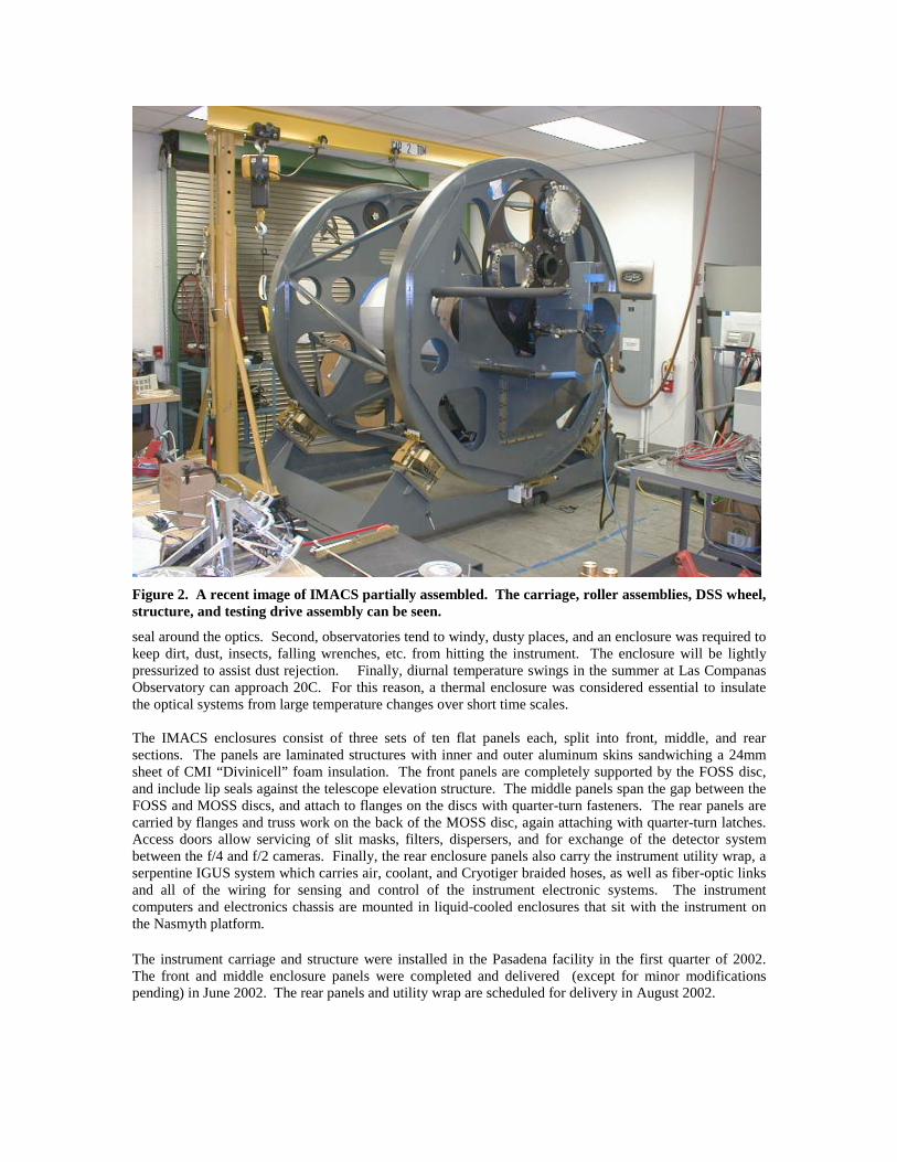
Figure 2. A recent image of IMACS partially assembled. The carriage, roller assemblies, DSS wheel,structure, and testing drive assembly can be seen.
seal around the optics. Second, observatories tend to windy, dusty places, and an enclosure was required tokeep dirt, dust, insects, falling wrenches, etc. from hitting the instrument. The enclosure will be lightlypressurized to assist dust rejection. Finally, diurnal temperature swings in the summer at Las CompanasObservatory can approach 20C. For this reason, a thermal enclosure was considered essential to insulatethe optical systems from large temperature changes over short time scales.
The IMACS enclosures consist of three sets of ten flat panels each, split into front, middle, and rearsections. The panels are laminated structures with inner and outer aluminum skins sandwiching a 24mmsheet of CMI “Divinicell” foam insulation. The front panels are completely supported by the FOSS disc,and include lip seals against the telescope elevation structure. The middle panels span the gap between theFOSS and MOSS discs, and attach to flanges on the discs with quarter-turn fasteners. The rear panels arecarried by flanges and truss work on the back of the MOSS disc, again attaching with quarter-turn latches.Access doors allow servicing of slit masks, filters, dispersers, and for exchange of the detector systembetween the f/4 and f/2 cameras. Finally, the rear enclosure panels also carry the instrument utility wrap, aserpentine IGUS system which carries air, coolant, and Cryotiger braided hoses, as well as fiber-optic linksand all of the wiring for sensing and control of the instrument electronic systems. The instrumentcomputers and electronics chassis are mounted in liquid-cooled enclosures that sit with the instrument onthe Nasmyth platform.
The instrument carriage and structure were installed in the Pasadena facility in the first quarter of 2002.The front and middle enclosure panels were completed and delivered (except for minor modificationspending) in June 2002. The rear panels and utility wrap are scheduled for delivery in August 2002.

9. INSTRUMENT ELECTRONICS AND SOFTWARE
IMACS has approximately 30 computer-controlled motion functions, most of which are operated by aircylinders, steppers, or servomotors. Additionally, there are stand-alone closed-loop control systems(Physique Instrumente piezo and servo stages), and approximately 25 temperature, pressure, and flowsensors, all of which are powered by two racks of electronics and controlled by software. Detaileddescriptions of the electronic and software systems are beyond the scope of this paper. As of July 2002,virtually all of the instrument control electronics are operational (with the exception of the DSS grating tiltand wheel drive systems) and are at least occasionally installed in the two electronics enclosures. Theprimary outstanding electronics work remaining is the fabrication and mounting of the instrument utilityand cable wraps, which is scheduled for completion in the fall of 2002. All of the software components arecurrently operational, and many of the engineering GUIs are in regular use during final testing andintegration of the instrument. Although the GUIs will continue to evolve, even beyond the ship date for theinstrument, the instrument software programs for mask cutting, motion control, guiding, and exposurecontrol are all functional.
CONCLUSIONS
A comprehensive report on the status of the IMACS project has been presented. Barring any unforeseendisasters, the instrument is currently scheduled for completion in late 2002.
ACKNOWLEDGMENTS
A virtual army of people has contributed to the design and construction of the IMACS instrument. Startingwith the instrument project team, the authors wish to thank the following; optical designers Harland Epps,Brian Sutin, and Steve Shectman; mechanical engineers Tyson Hare, Steve Gunnels and Tim Bond;drafters Richard Cleary and Julie Myers, electrical engineers David Carr and Alan Baggish; electronicstechnicians Joe Asa and Jorge Estrada; software engineers Christoph Birk, Ken Clardy, and GregBredthauer, detector scientists Ian Thompson and Greg Burley; machinists Vince Kowal, Jerson Castillo,and Robert Storts; purchasing wizards Jeanette Stone and Sharon Kelly; and last but not least, SteveWilson, Earl Harris, Greg Ortiz, and Scott Rubel, who helped in too many ways and on too many occasionsto count. The authors also with to thank the dozens of outside shops that have fabricated hundreds of thethousands of parts which make IMACS, but especially Joe Appels of Tucson Optical Research Corp, DaveBoese and Steve Fox of Martinez and Turek, Franz Rettig of Rettig Machine, and Tony Perera of SpectrumThin Film Labs.
REFERENCES
1. A. Dressler, B. M. Sutin. B. C. Bigelow, “Science with IMACS on Magellan”, Proc. SPIE 4834, 20022. H. W. Epps, B. M. Sutin, “Passively-athermalized construction optical design for the IMACS short
camera”, Proc. SPIE 4841, 20023. B. C. Bigelow, A. Dressler, “IMACS: the multi-object spectrograph and imager for the Magellan 6.5m
Baade telescope; a status report”, Proc. SPIE 4841, 20024. B. M. Sutin, A. MacWilliam, “Multi-object high-resolution echellette spectroscopy with IMACS”,
Proc. SPIE 4841, 20025. S. A. Shectman, M. Johns, “Magellan Telescopes”, Proc. SPIE 4837, 20026. R. A. Bernstein, S. A. Shectman, S. M. Gunnels, S. Mochnacki, “MIKE: a double-echelle spectrograph
for the Magellan telescopes” Proc. SPIE 4841, 20027. S. A. Shectman, “The optical design of the Magellan Project 6.5-m Telescope”, Proc. SPIE 2199, 19948. H. W. Epps, “Development of high-performance lenses for astronomical spectrographs”, Proc. SPIE
3355, 19989. R. G. Fata and D. G. Fabricant, “Mounting large lenses in wide-field instruments for the converted
MMT”, Proc SPIE 3355, 199810. R. G. Murowinski, T. Bond, D. Crampton, et. al, “Gemini multiobject spectrographs”, Proc. SPIE
3355, p. 188, 1998


![Untitled Document [instrumentation.obs.carnegiescience.edu]instrumentation.obs.carnegiescience.edu/ccd/parts/AM29F040B.pdf · A0–A18 = Address Inputs DQ0–DQ7 = Data Input/Output](https://img.pdfslide.net/doc/110x75/5f55abc6e8d2ef0791257dfb/untitled-document-a0aa18-address-inputs-dq0adq7-data-inputoutput-ce.jpg)