Embed Size (px)
Citation preview
© 2014 The MathWorks, Inc.
Improve Safety and Reliability of Medical
Devices with Modeling and Simulation
Arvind Ananthan
Medical Devices Industry ManagerMathWorksNatick, USA
“Modeling and simulation (M&S)
is getting information about
how something will behave
without actually testing it in real life.” – Wikipedia
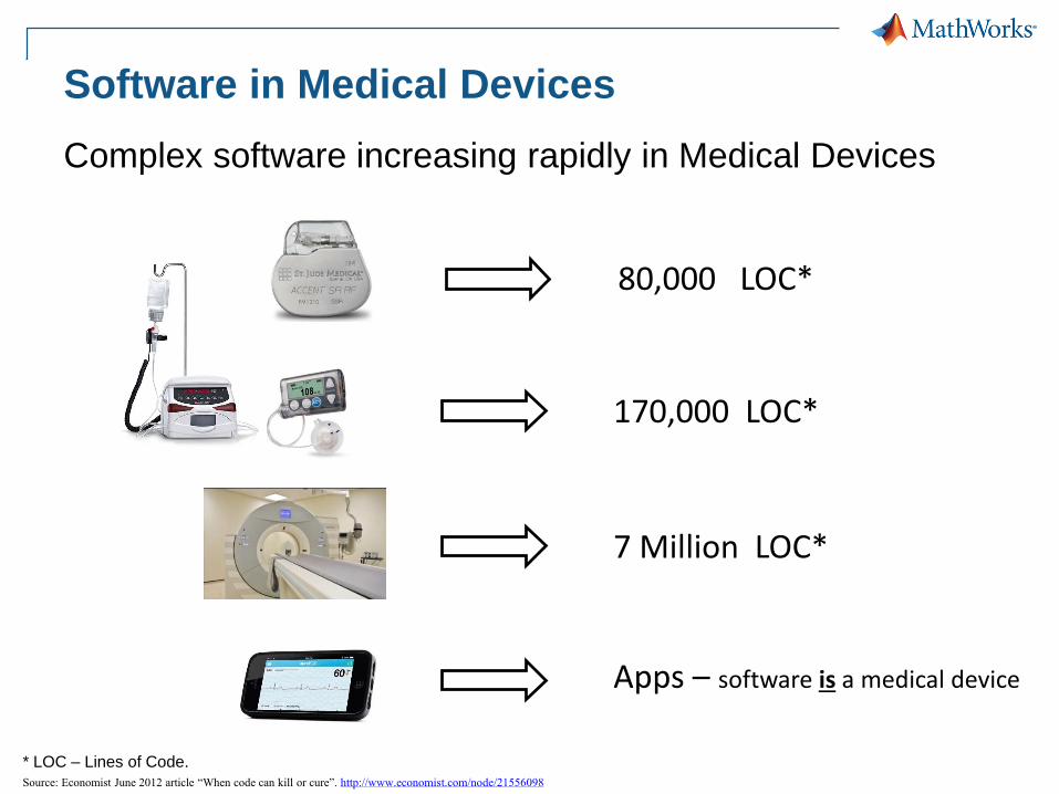
Software in Medical Devices
Complex software increasing rapidly in Medical Devices
* LOC – Lines of Code.
Source: Economist June 2012 article “When code can kill or cure”. http://www.economist.com/node/21556098
80,000 LOC*
170,000 LOC*
7 Million LOC*
Apps – software is a medical device
5
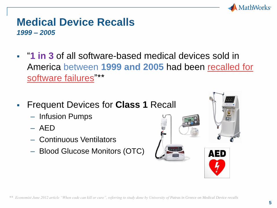
Medical Device Recalls1999 – 2005
“1 in 3 of all software-based medical devices sold in
America between 1999 and 2005 had been recalled for
software failures”**
Frequent Devices for Class 1 Recall
– Infusion Pumps
– AED
– Continuous Ventilators
– Blood Glucose Monitors (OTC)
** Economist June 2012 article “When code can kill or cure”, referring to study done by University of Patras in Greece on Medical Device recalls
6
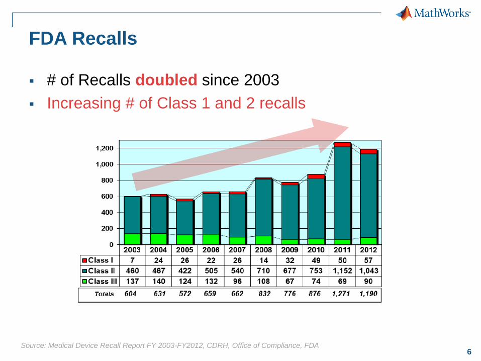
FDA Recalls
# of Recalls doubled since 2003
Increasing # of Class 1 and 2 recalls
Source: Medical Device Recall Report FY 2003-FY2012, CDRH, Office of Compliance, FDA

8
Recall Cause Categories
Majority of Recall Reasons related to 820.30 Design
Controls
– Design and revision of that design during the lifetime of the
device
9
Electrical
Components
EDA
Mechanical
Components
MCAD/
MCAE
Embeddable
Algorithms
Algorithm
Design
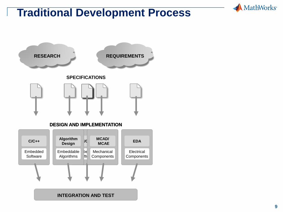
Traditional Development Process
SPECIFICATIONS
DESIGN AND IMPLEMENTATION
RESEARCH REQUIREMENTS
Embedded
Software
C/C++
INTEGRATION AND TEST
Electrical
Components
EDA
Mechanical
Components
MCAD/
MCAE
Embeddable
Algorithms
Algorithm
Design
DESIGN AND IMPLEMENTATION
Embedded
Software
C/C++
10
Electrical
Components
EDA
Mechanical
Components
MCAD/
MCAE
Embeddable
Algorithms
Algorithm
Design
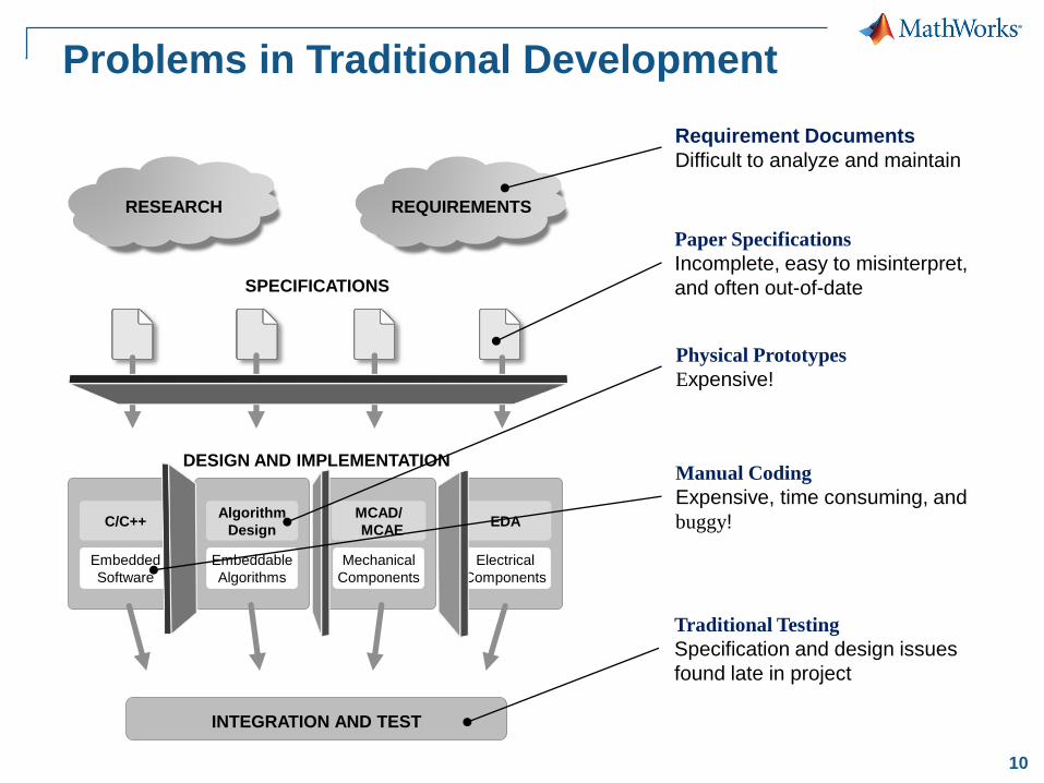
Problems in Traditional Development
SPECIFICATIONS
DESIGN AND IMPLEMENTATION
RESEARCH REQUIREMENTS
Embedded
Software
C/C++
Paper Specifications
Incomplete, easy to misinterpret,
and often out-of-date
Physical Prototypes
Expensive!
Manual Coding
Expensive, time consuming, and
buggy!
Requirement Documents
Difficult to analyze and maintain
INTEGRATION AND TEST
Traditional Testing
Specification and design issues
found late in project
11
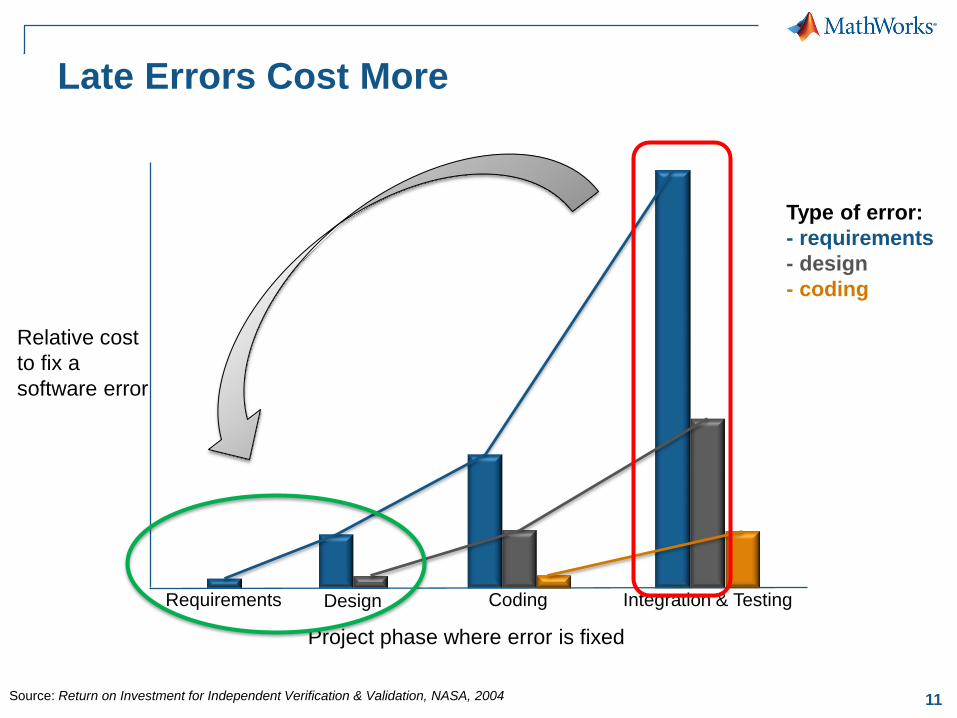
Late Errors Cost More
Requirements Design Coding Integration & Testing
Relative cost
to fix a
software error
Project phase where error is fixed
Type of error:
- requirements
- design
- coding
Source: Return on Investment for Independent Verification & Validation, NASA, 2004

12
Solutions1. Multi-domain System Modeling
13
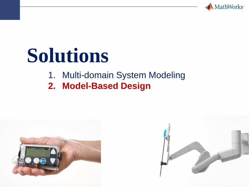
Solutions1. Multi-domain System Modeling
2. Model-Based Design
14
Solutions1. Multi-domain System Modeling
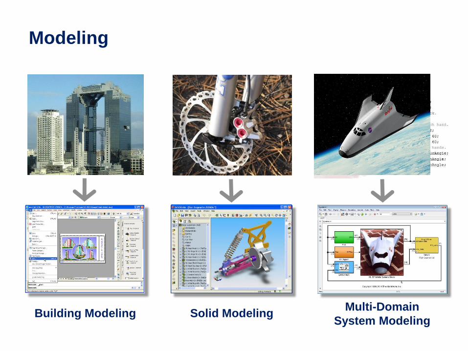
Modeling
Building Modeling Solid ModelingMulti-Domain
System Modeling
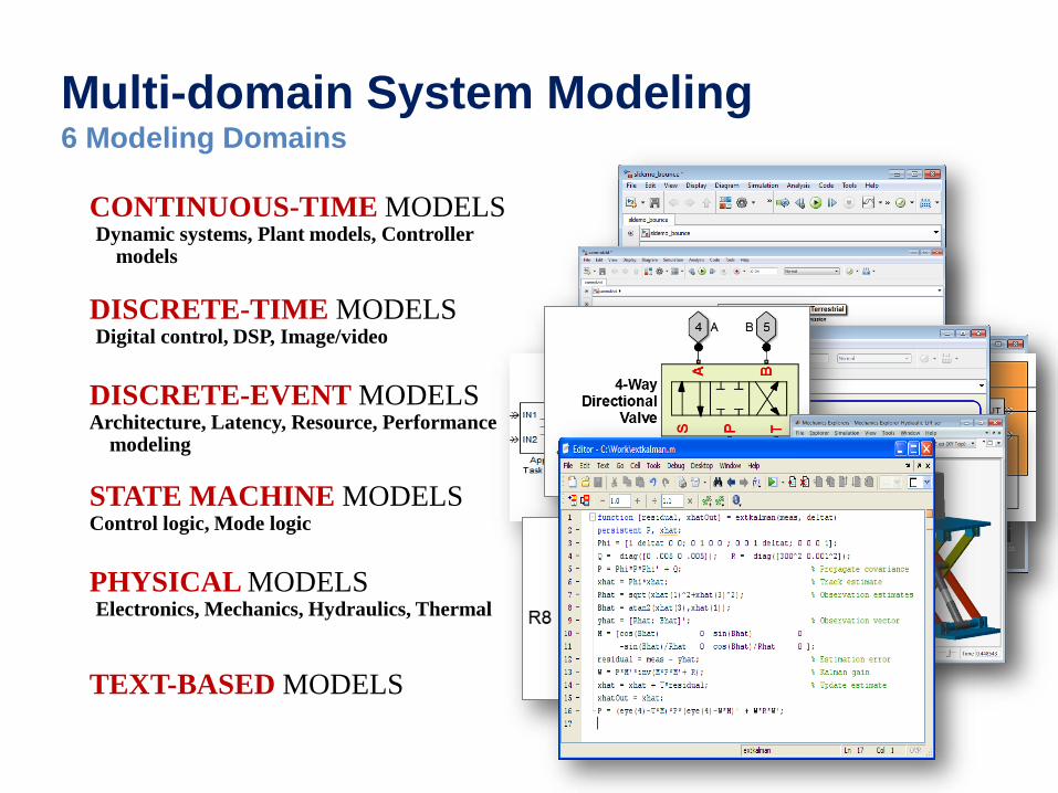
Multi-domain System Modeling6 Modeling Domains
CONTINUOUS-TIME MODELSDynamic systems, Plant models, Controller
models
DISCRETE-TIME MODELSDigital control, DSP, Image/video
DISCRETE-EVENT MODELSArchitecture, Latency, Resource, Performance
modeling
STATE MACHINE MODELSControl logic, Mode logic
PHYSICAL MODELSElectronics, Mechanics, Hydraulics, Thermal
TEXT-BASED MODELS
17
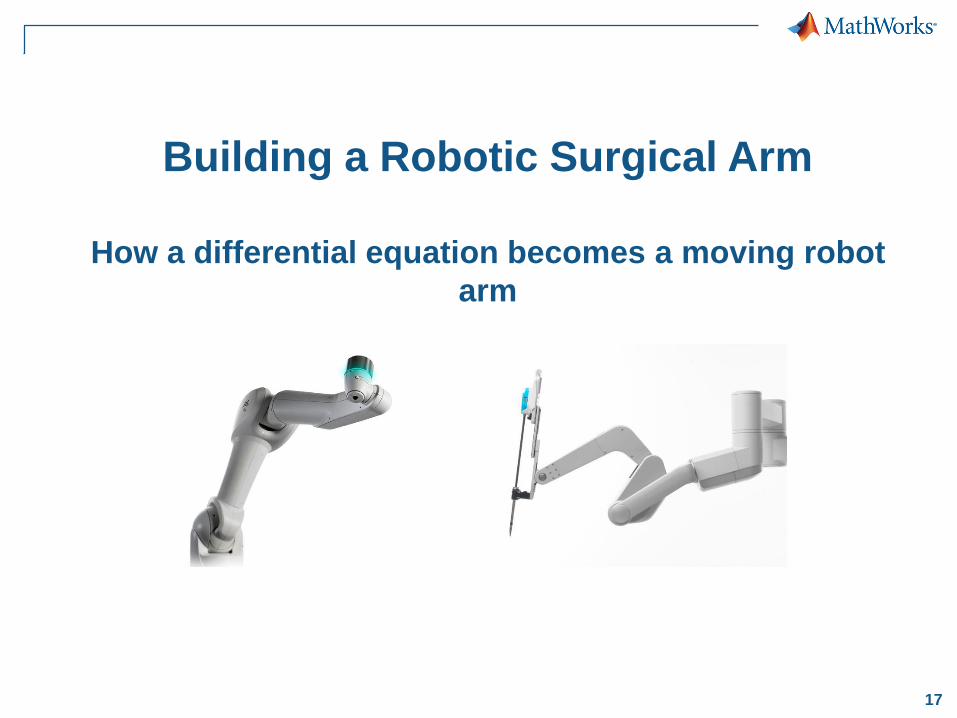
Building a Robotic Surgical Arm
How a differential equation becomes a moving robot
arm
18
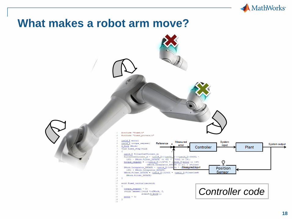
What makes a robot arm move?
Controller code
19
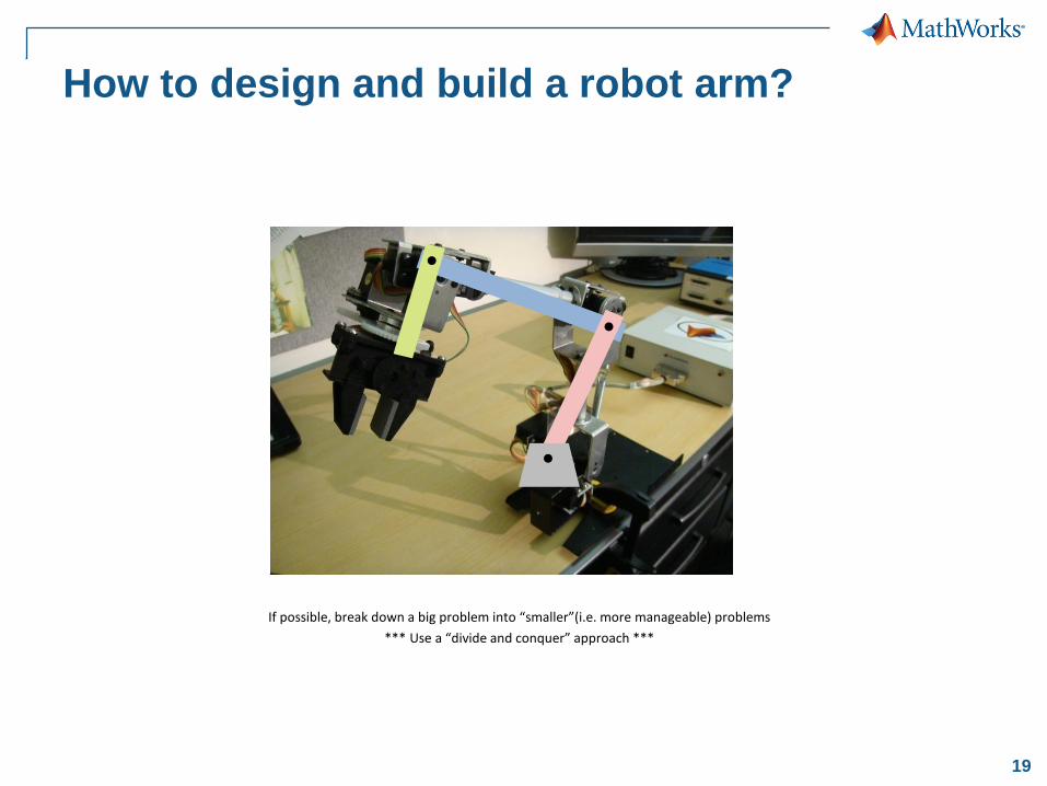
How to design and build a robot arm?
If possible, break down a big problem into “smaller”(i.e. more manageable) problems
*** Use a “divide and conquer” approach ***

20
So, where do we really start?
If possible, break down a big problem into “smaller”(i.e. more manageable) problems
*** Use a “divide and conquer” approach ***

21
So, where do we really start?
Understand the underlying mathematics/physics of the problem
q
r
X
Y
22
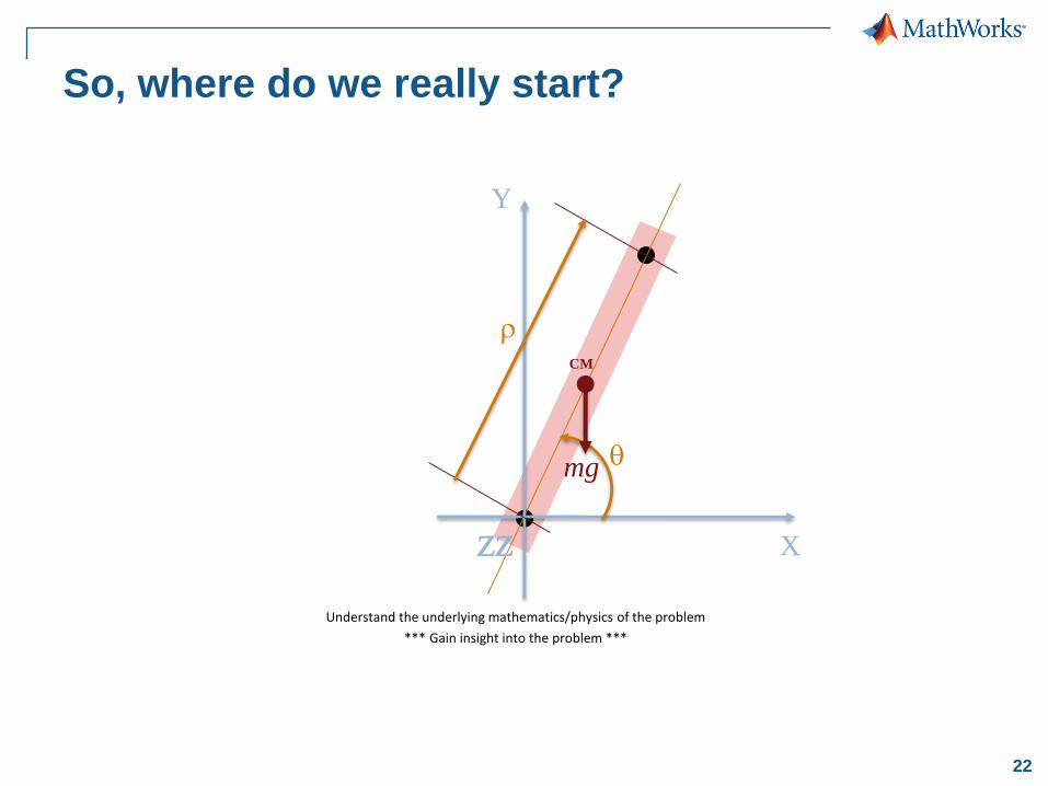
So, where do we really start?
Understand the underlying mathematics/physics of the problem
*** Gain insight into the problem ***
q
r
X
Y
ZZ
mg
CM
23
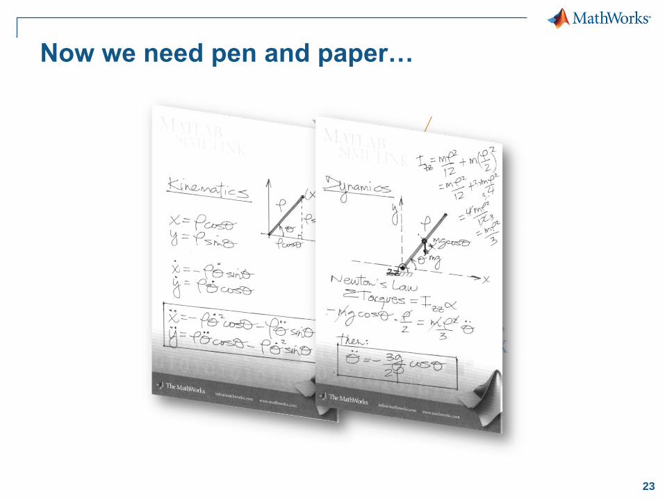
Now we need pen and paper…
Understand the underlying mathematics/physics of the problem
*** Gain insight into the problem ***
q
r
X
Y
ZZ
mg
mgcos(q)
CM

24
Or, we can use the Symbolic Math Toolbox
notebook interface…
• To help us derive the dynamic equations analytically
• To find analytic (when possible) and/or numerical solutions to the problem
26
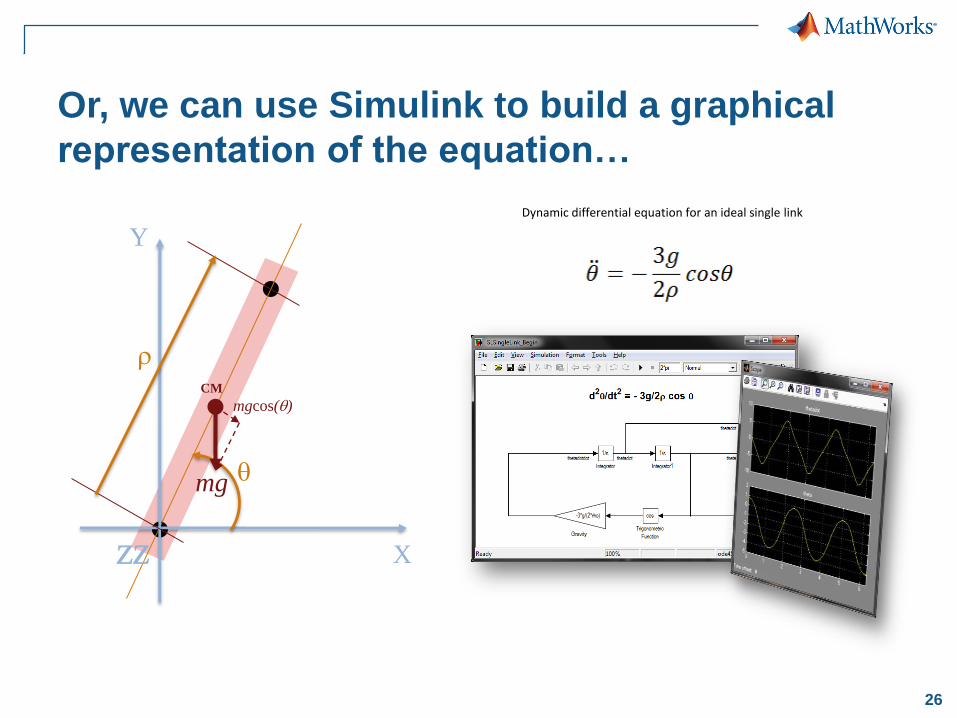
Or, we can use Simulink to build a graphical
representation of the equation…
q
r
X
Y
ZZ
mg
mgcos(q)
CM
Dynamic differential equation for an ideal single link

28
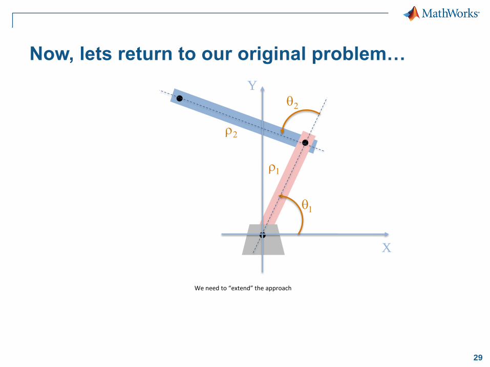
Now, lets return to our original problem…
We need to “extend” the approach
29
Now, lets return to our original problem…
We need to “extend” the approach
X
Y
q1
q2
r1
r2
30
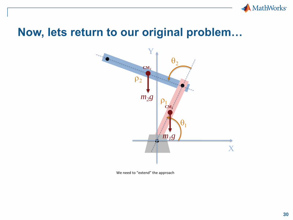
Now, lets return to our original problem…
We need to “extend” the approach
X
Y
q1
q2
r1
r2
m2g
CM2
m1g
CM1

31
X
Y
q1
q2
r1
r2
m2g
CM2
m1g
CM1
And quickly, things start to get ugly…
We need to “extend” the approach
32
X
Y
q1
q2
r1
r2
m2g
CM2
m1g
CM1
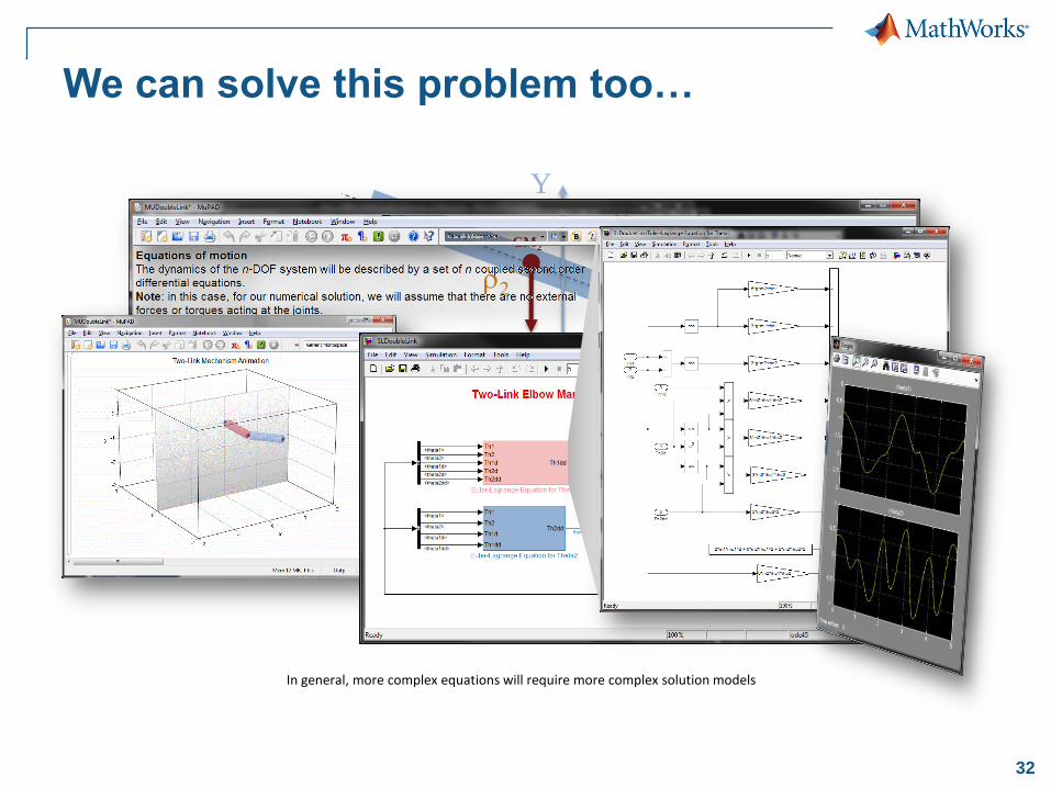
We can solve this problem too…
In general, more complex equations will require more complex solution models
34
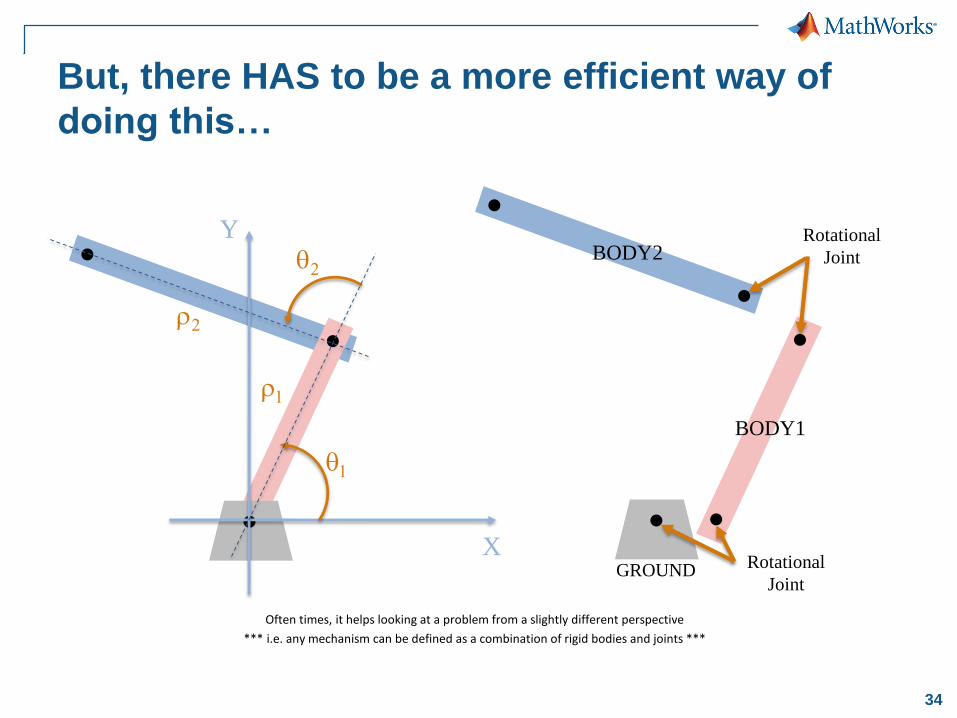
But, there HAS to be a more efficient way of
doing this…
Often times, it helps looking at a problem from a slightly different perspective
*** i.e. any mechanism can be defined as a combination of rigid bodies and joints ***
GROUND
BODY1
BODY2
Rotational
Joint
Rotational
Joint
X
Y
q1
q2
r1
r2
35
X
Y
q1
q2
r1
r2
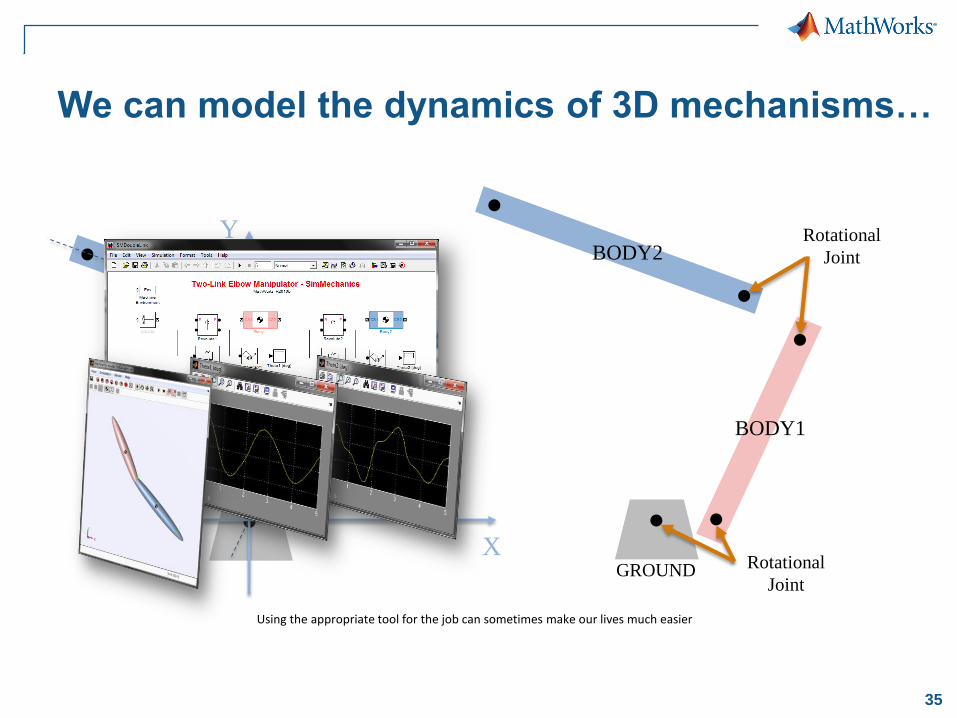
We can model the dynamics of 3D mechanisms…
Using the appropriate tool for the job can sometimes make our lives much easier
GROUND
BODY1
BODY2
Rotational
Joint
Rotational
Joint
36
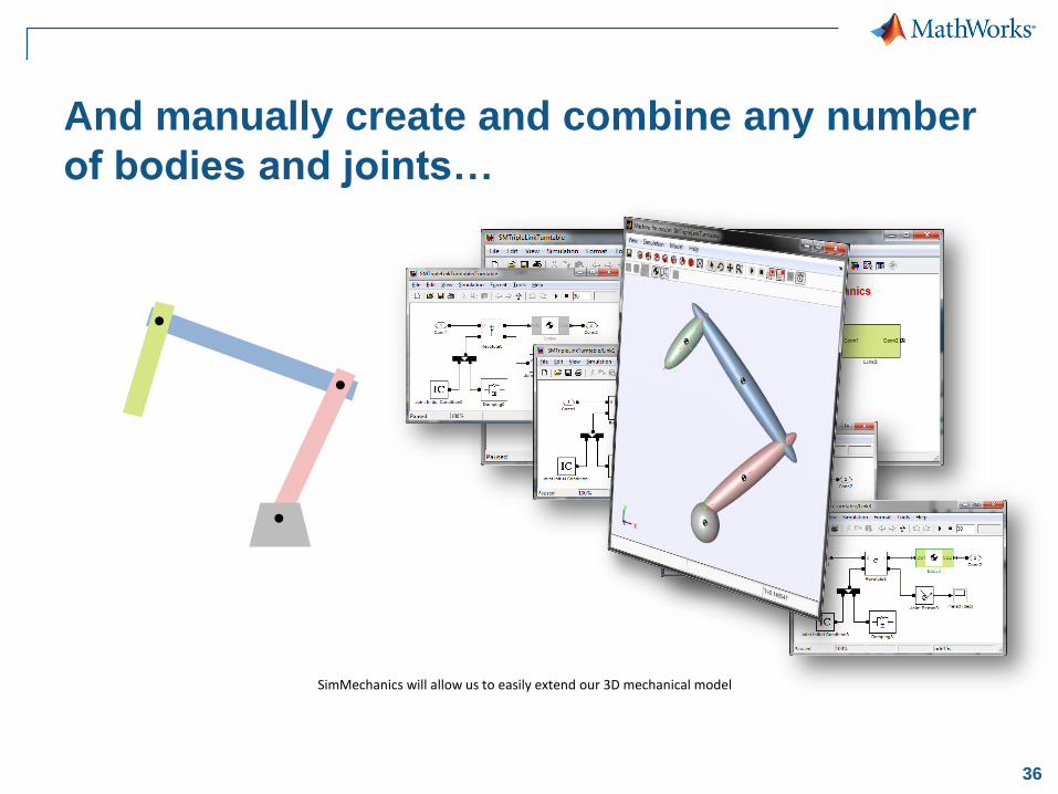
And manually create and combine any number
of bodies and joints…
SimMechanics will allow us to easily extend our 3D mechanical model
37
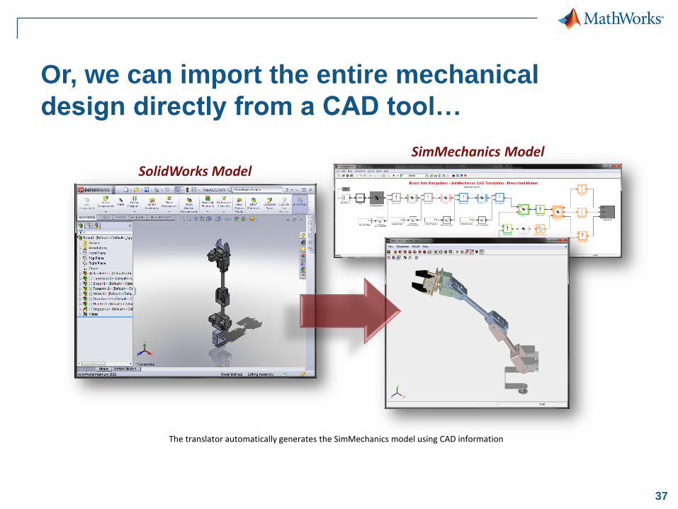
Or, we can import the entire mechanical
design directly from a CAD tool…
The translator automatically generates the SimMechanics model using CAD information
SolidWorks Model
SimMechanics Model
38
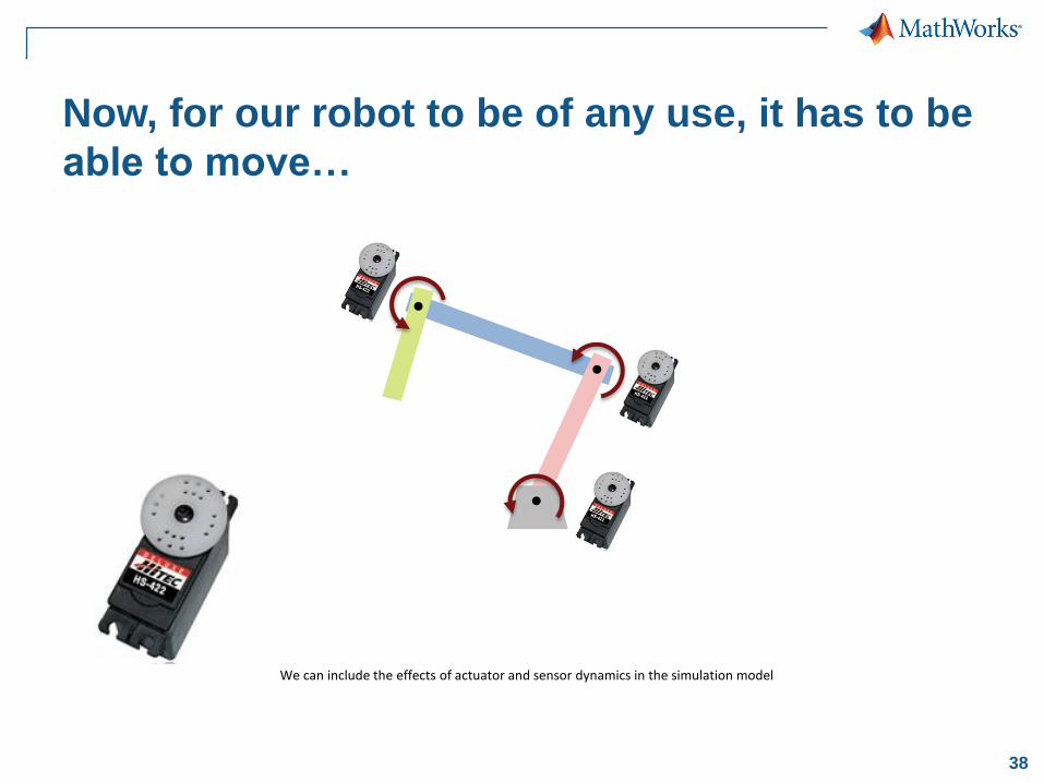
Now, for our robot to be of any use, it has to be
able to move…
We can include the effects of actuator and sensor dynamics in the simulation model
39
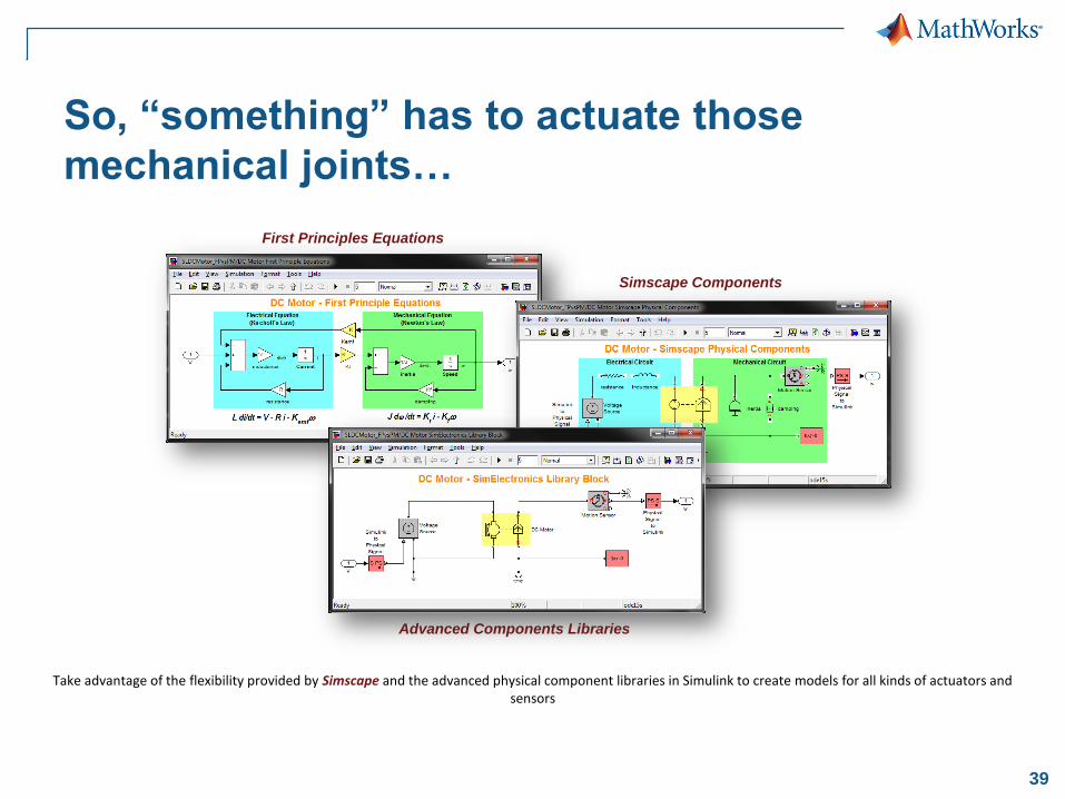
So, “something” has to actuate those
mechanical joints…
First Principles Equations
Simscape Components
Advanced Components Libraries
Take advantage of the flexibility provided by Simscape and the advanced physical component libraries in Simulink to create models for all kinds of actuators and sensors
40
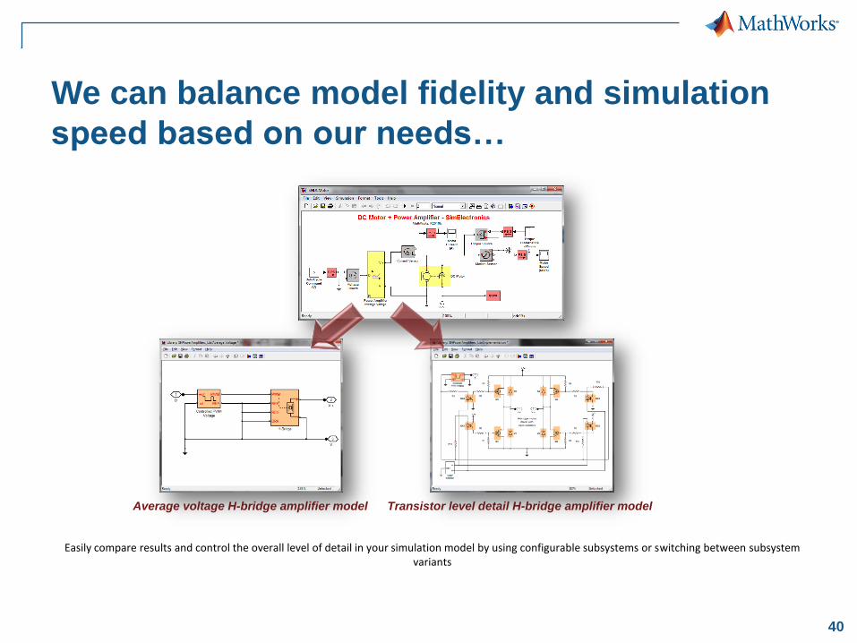
We can balance model fidelity and simulation
speed based on our needs…
Easily compare results and control the overall level of detail in your simulation model by using configurable subsystems or switching between subsystem variants
Average voltage H-bridge amplifier model Transistor level detail H-bridge amplifier model
41
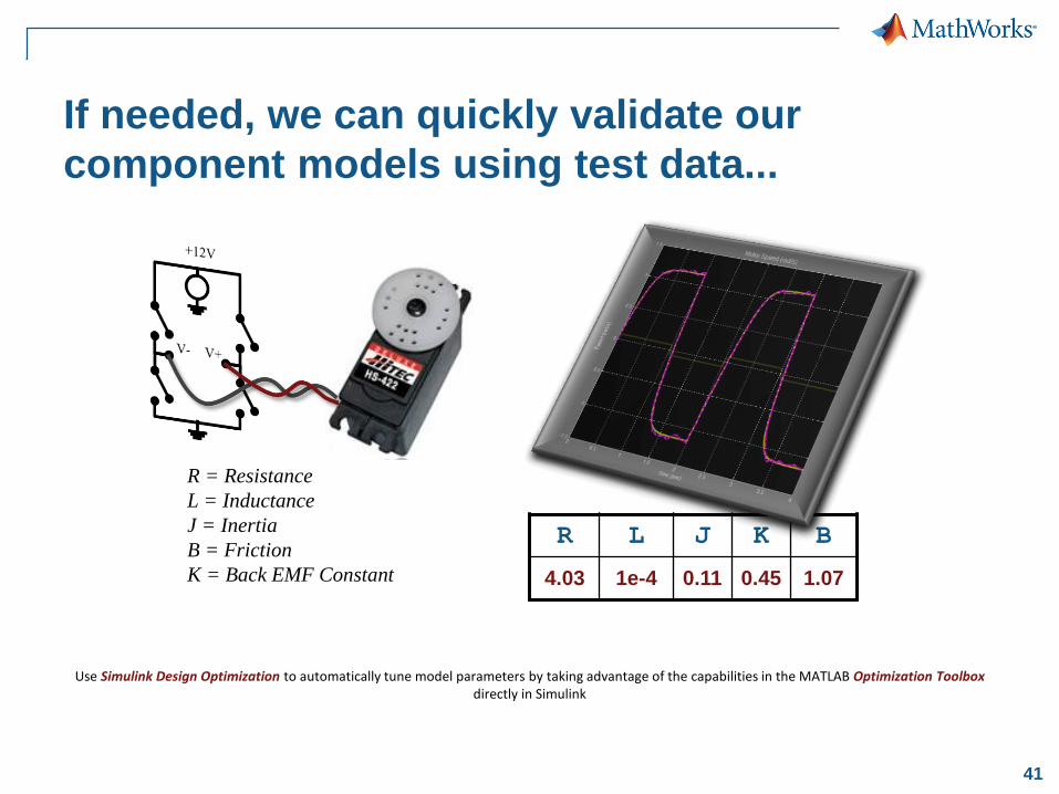
If needed, we can quickly validate our
component models using test data...
Use Simulink Design Optimization to automatically tune model parameters by taking advantage of the capabilities in the MATLAB Optimization Toolbox directly in Simulink
R L J K B
3 0.01 0.01 0.02 0.5
R = Resistance
L = Inductance
J = Inertia
B = Friction
K = Back EMF Constant
R L J K B
4.03 1e-4 0.11 0.45 1.07
42
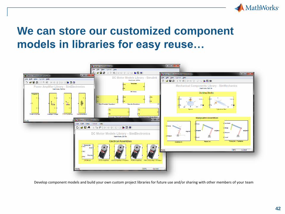
We can store our customized component
models in libraries for easy reuse…
Develop component models and build your own custom project libraries for future use and/or sharing with other members of your team

43
So far, we have built a dynamic model of our
plant…
44
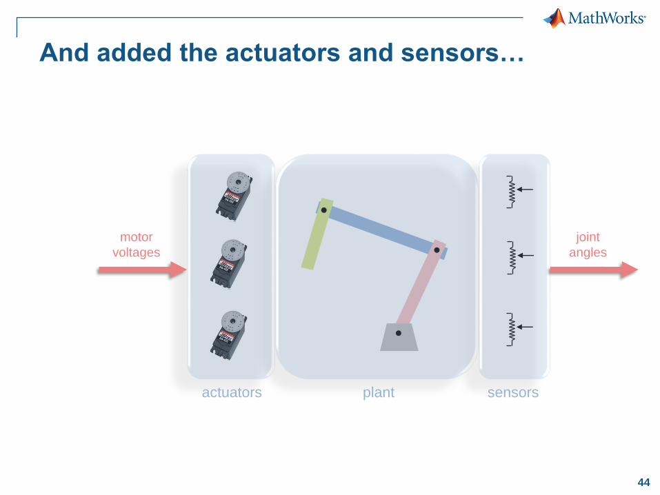
And added the actuators and sensors…
motor
voltages
joint
angles
actuators sensorsplant
45
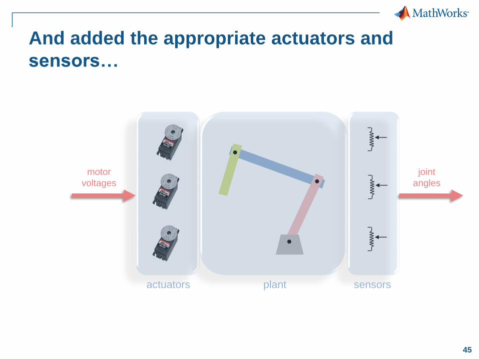
And added the appropriate actuators and
sensors…
motor
voltages
joint
angles
actuators sensorsplant
46
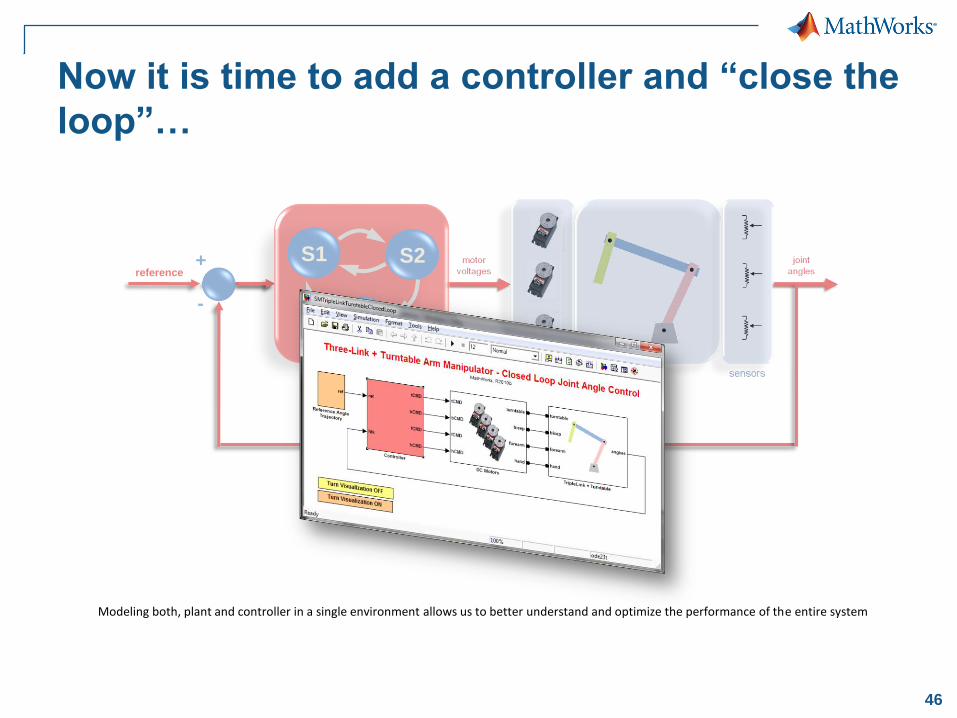
Now it is time to add a controller and “close the
loop”…
reference+
-
controller
Modeling both, plant and controller in a single environment allows us to better understand and optimize the performance of the entire system
S1 S2
S3
47
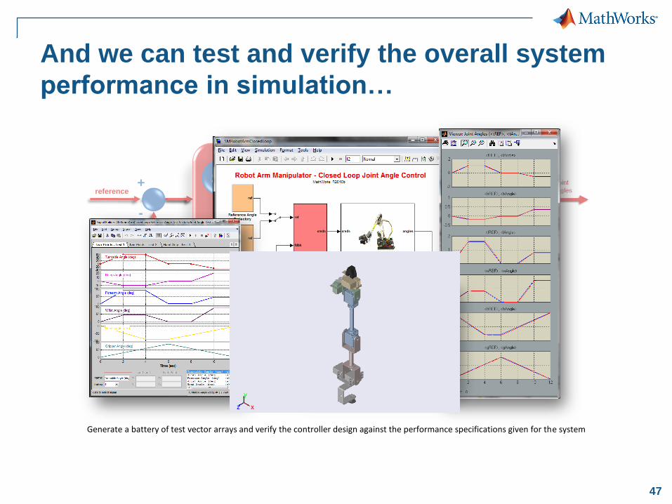
And we can test and verify the overall system
performance in simulation…
Generate a battery of test vector arrays and verify the controller design against the performance specifications given for the system
reference+
-
controller
S1 S2
S3
49
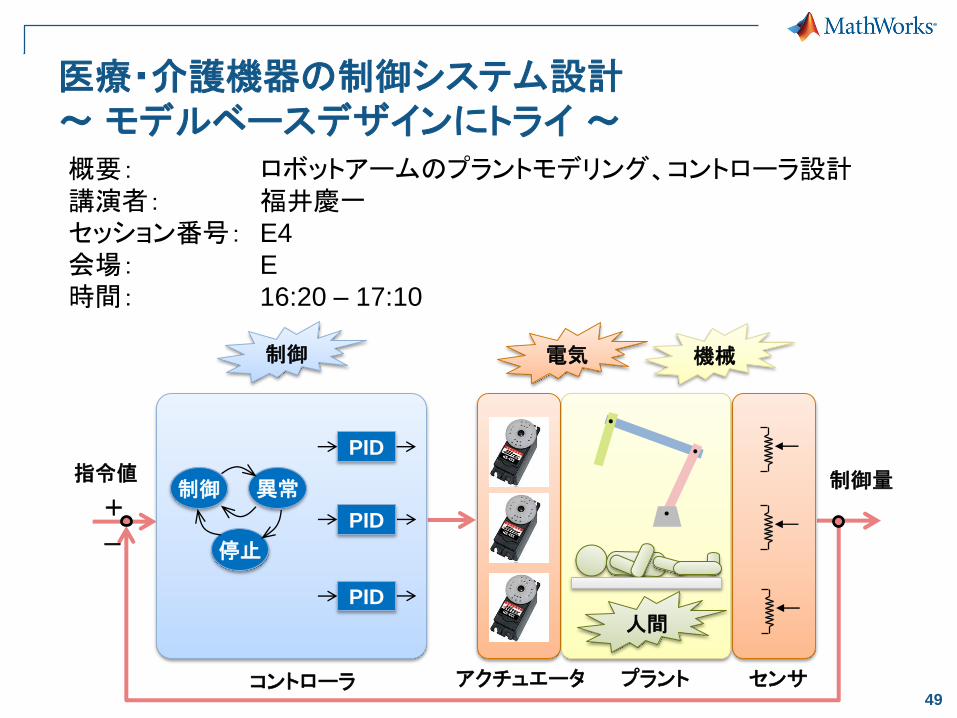
医療・介護機器の制御システム設計~ モデルベースデザインにトライ ~
コントローラ
制御 異常
停止
PID
PID
PID
アクチュエータ センサプラント
制御 電気 機械
+
-
人間
指令値 制御量
概要: ロボットアームのプラントモデリング、コントローラ設計講演者: 福井慶一セッション番号: E4
会場: E
時間: 16:20 – 17:10
50
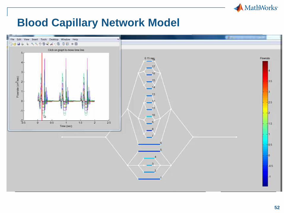
Modeling Blood Flow
in Capillary Networksat Draper Labs, Cambridge, MA
Simulating physiological network system for
synthetic organ development
51
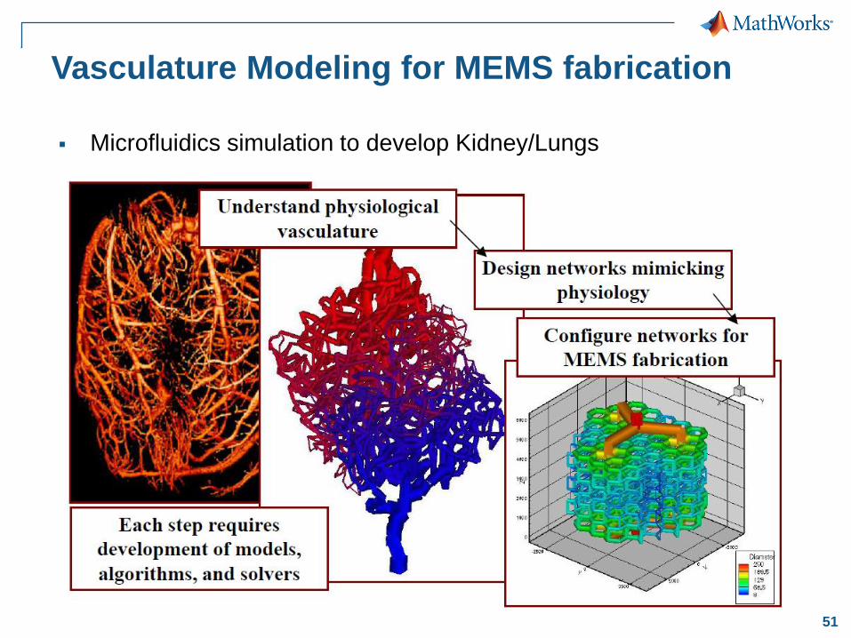
Vasculature Modeling for MEMS fabrication
Microfluidics simulation to develop Kidney/Lungs
52
Blood Capillary Network Model
54
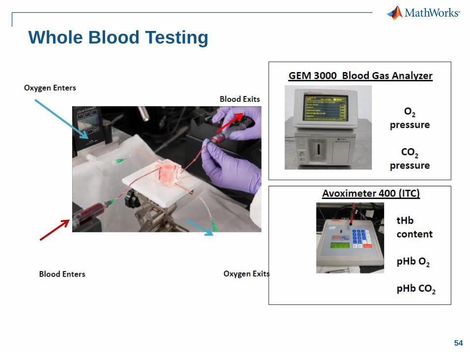
Whole Blood Testing
55
Mock Circulatory Loop (MCL) Model
for Testing Heart Pumps (or VADs)
56
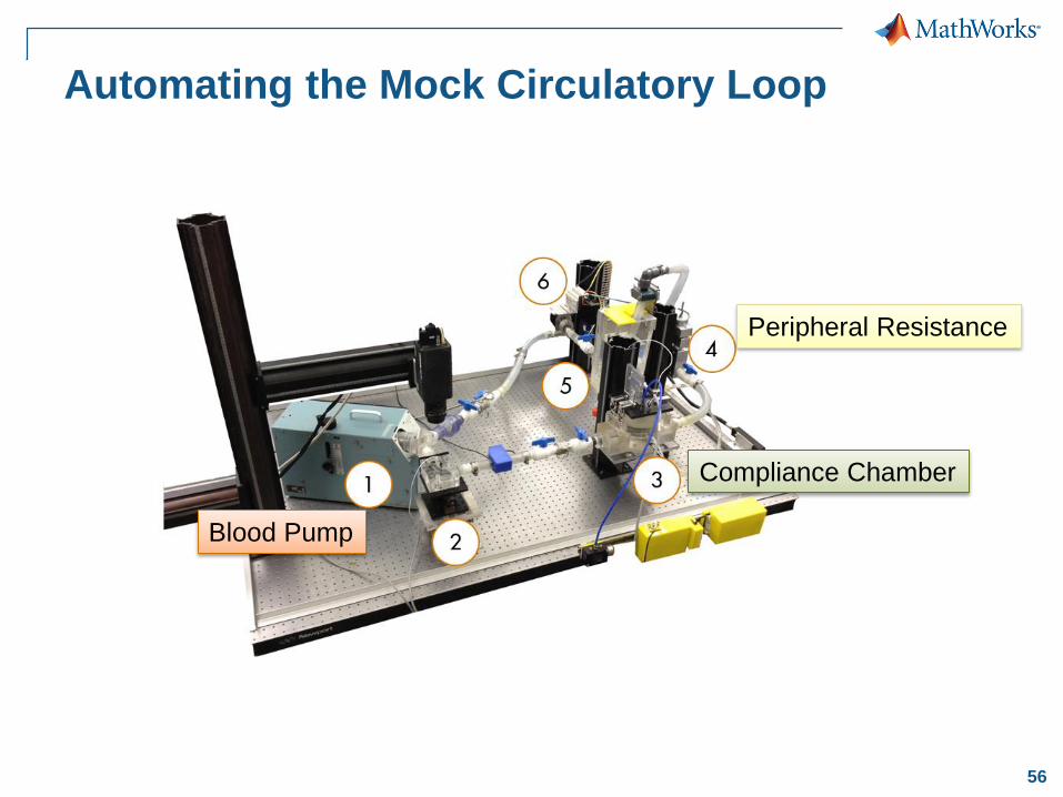
Blood Pump
Compliance Chamber
Peripheral Resistance
Automating the Mock Circulatory Loop
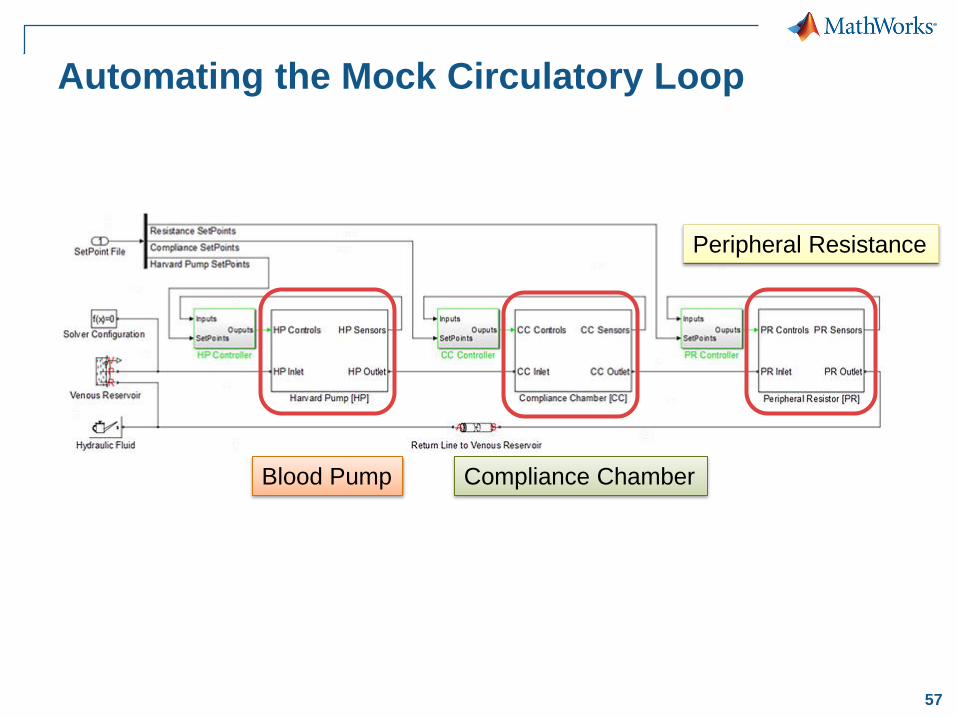
57
Automating the Mock Circulatory Loop
Blood Pump Compliance Chamber
Peripheral Resistance
58
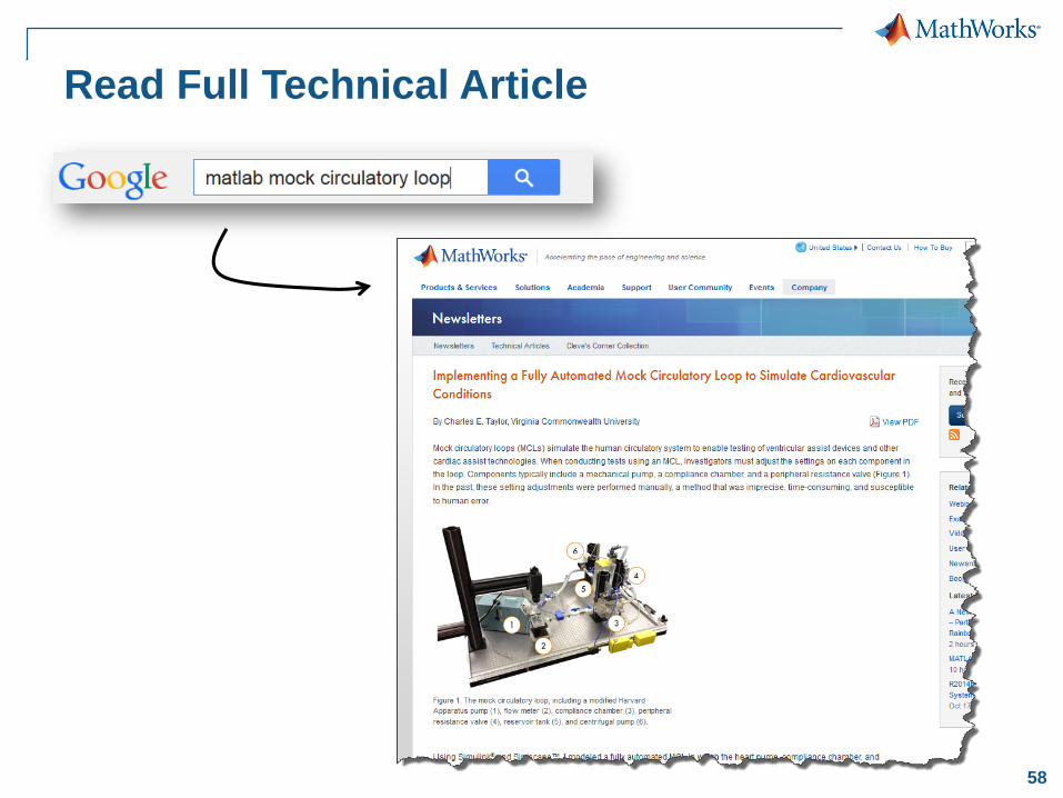
Read Full Technical Article
59
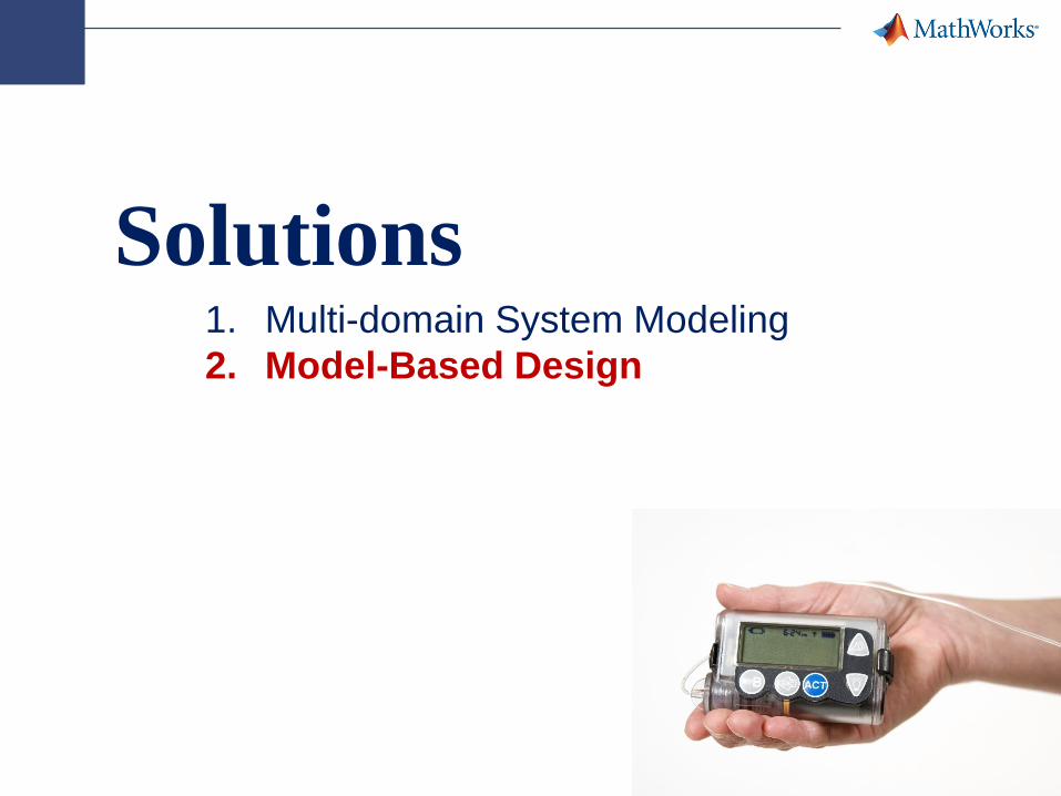
Solutions1. Multi-domain System Modeling
2. Model-Based Design
60
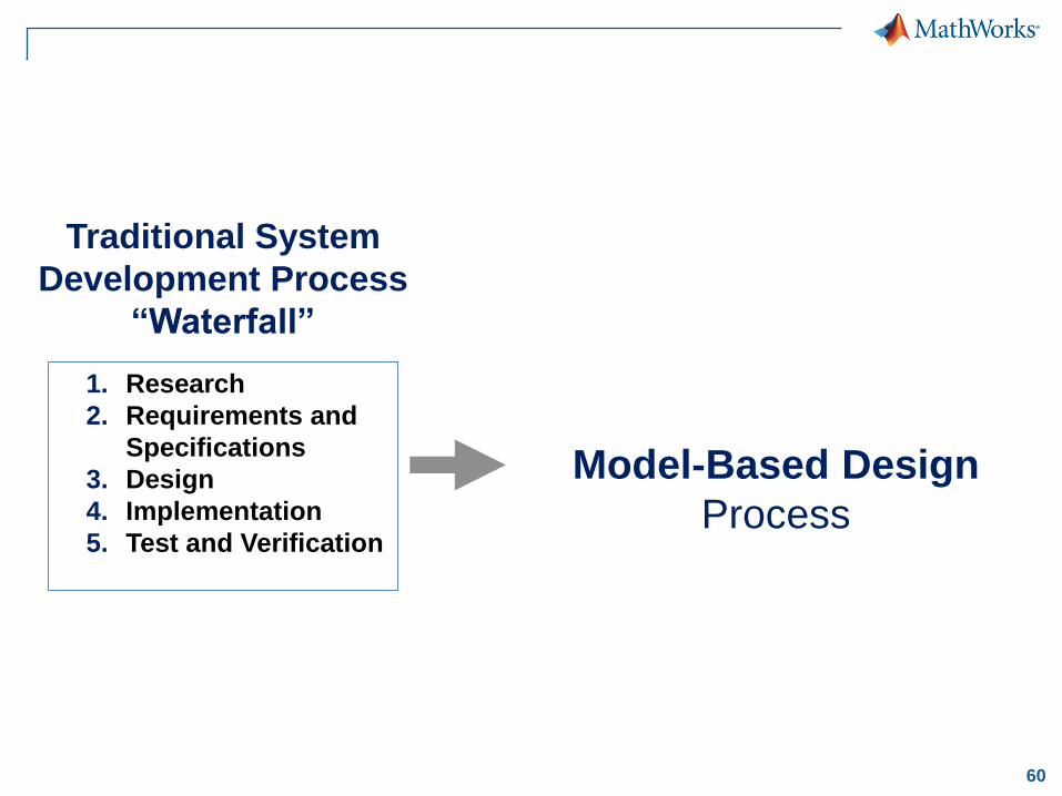
Model-Based Design
Process
1. Research
2. Requirements and
Specifications
3. Design
4. Implementation
5. Test and Verification
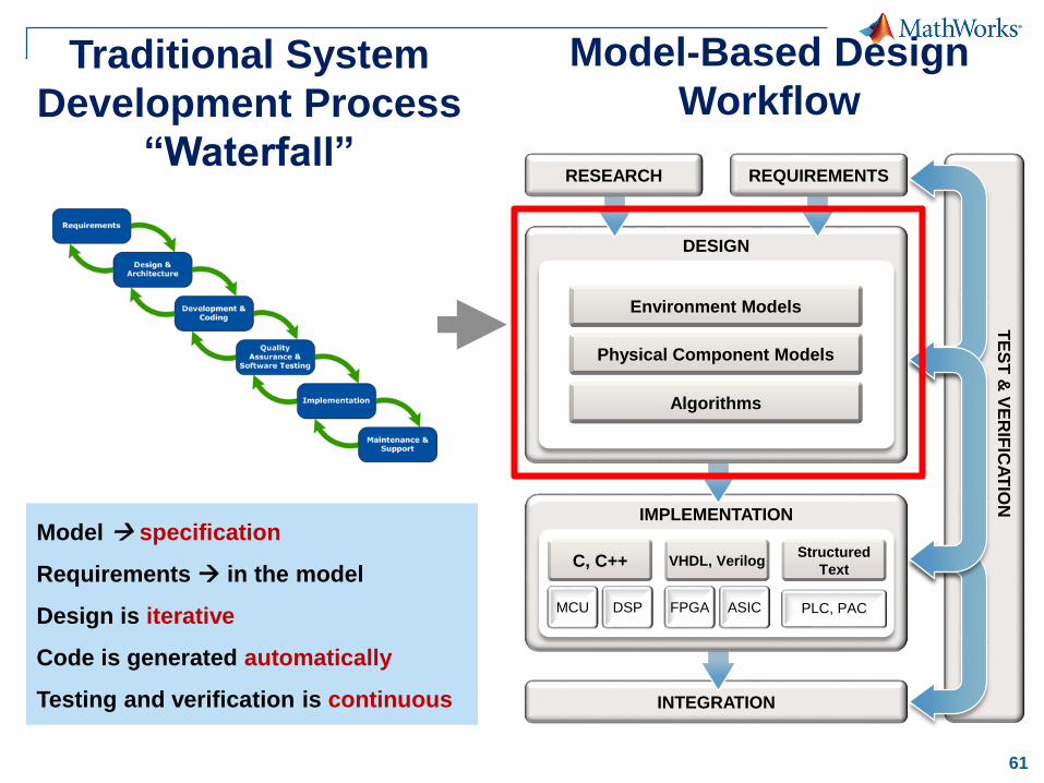
Traditional System
Development Process
“Waterfall”
61
INTEGRATION
IMPLEMENTATION
DESIGN
Environment Models
Physical Component Models
Algorithms
Structured
TextVHDL, VerilogC, C++
TE
ST
& V
ER
IFIC
AT
ION
RESEARCH REQUIREMENTS
PLC, PACMCU DSP FPGA ASIC
Model-Based Design
WorkflowTraditional System
Development Process
“Waterfall”
Model specification
Requirements in the model
Design is iterative
Code is generated automatically
Testing and verification is continuous
62
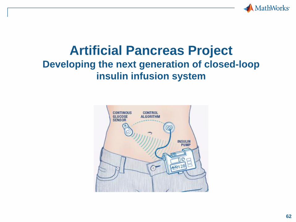
Artificial Pancreas ProjectDeveloping the next generation of closed-loop
insulin infusion system
63
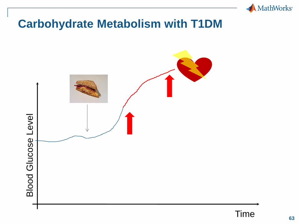
Carbohydrate Metabolism with T1DM
Time
Blo
od G
lucose L
evel
64
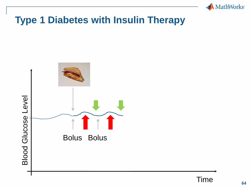
Type 1 Diabetes with Insulin Therapy
Time
Blo
od G
lucose L
evel
Bolus Bolus
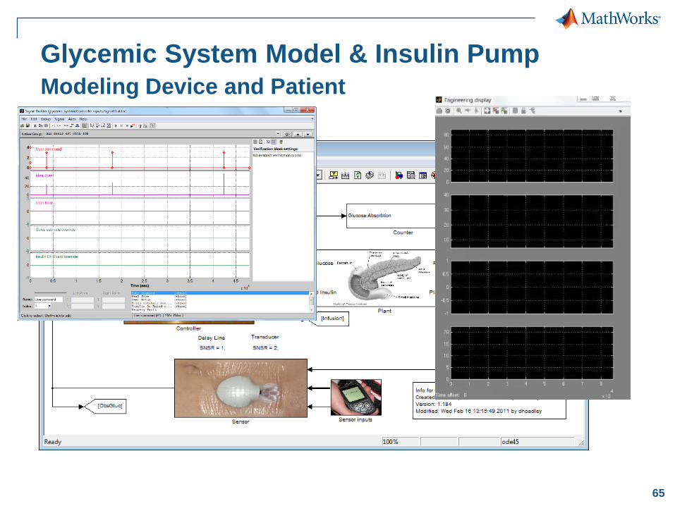
65
Glycemic System Model & Insulin Pump
Modeling Device and Patient
66
DESIGN
RESEARCH
Partitioning
Physical Components
Environment Models
IMPLEMENTATION
MCU DSP FPGA ASIC
Structured
TextVHDL, Verilog
PLC
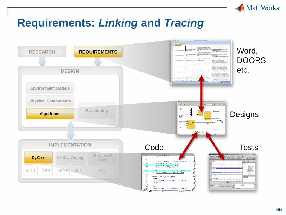
Requirements: Linking and Tracing
Tests
Word,
DOORS,
etc.
Algorithms
REQUIREMENTS
C, C++
Code
Designs
67
INTEGRATION
IMPLEMENTATION
MCU DSP FPGA ASIC
Structured
TextVHDL, VerilogC, C++
PLC
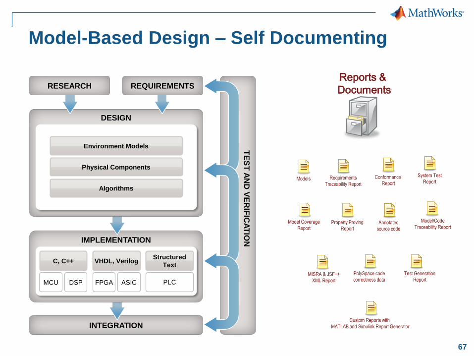
Model-Based Design – Self Documenting
DESIGN
RESEARCH REQUIREMENTS
Environment Models
Physical Components
Algorithms
TE
ST
AN
D V
ER
IFIC
AT
ION
Models Requirements
Traceability Report
Conformance
Report
System Test
Report
Model Coverage
ReportProperty Proving
ReportAnnotated
source code
Model/Code
Traceability Report
MISRA & JSF++
XML Report
PolySpace code
correctness data
Test Generation
Report
Reports &
Documents
Custom Reports with
MATLAB and Simulink Report Generator
68
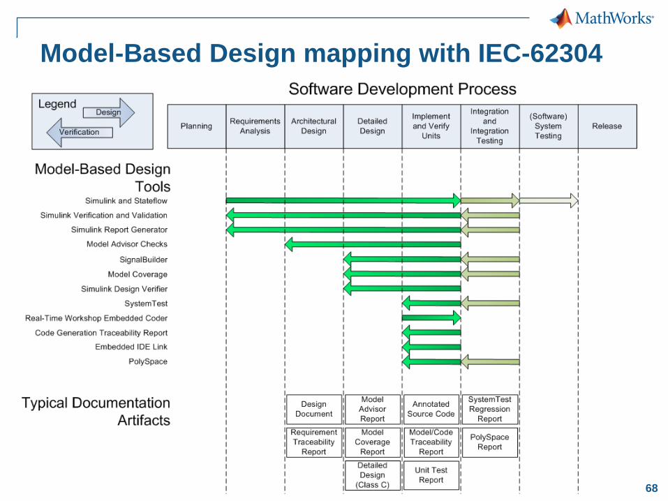
Model-Based Design mapping with IEC-62304
70
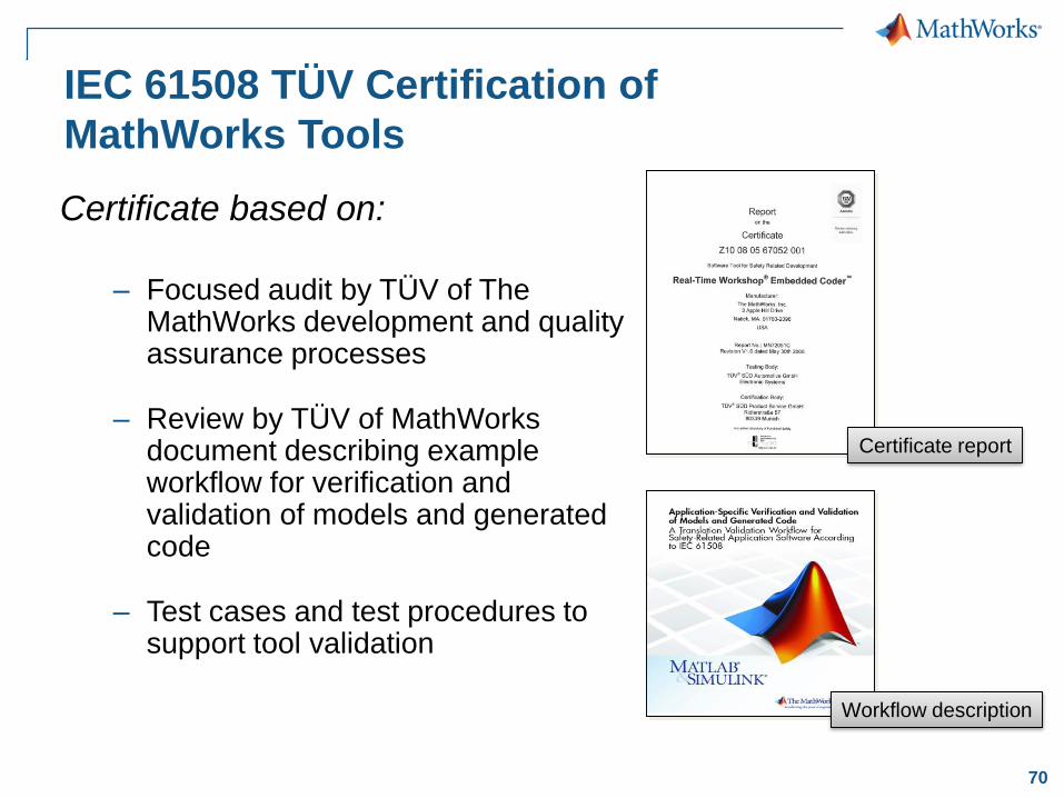
IEC 61508 TÜV Certification of
MathWorks Tools
Certificate based on:
– Focused audit by TÜV of The MathWorks development and quality assurance processes
– Review by TÜV of MathWorks document describing example workflow for verification and validation of models and generated code
– Test cases and test procedures to support tool validation
Certificate report
Workflow description
71
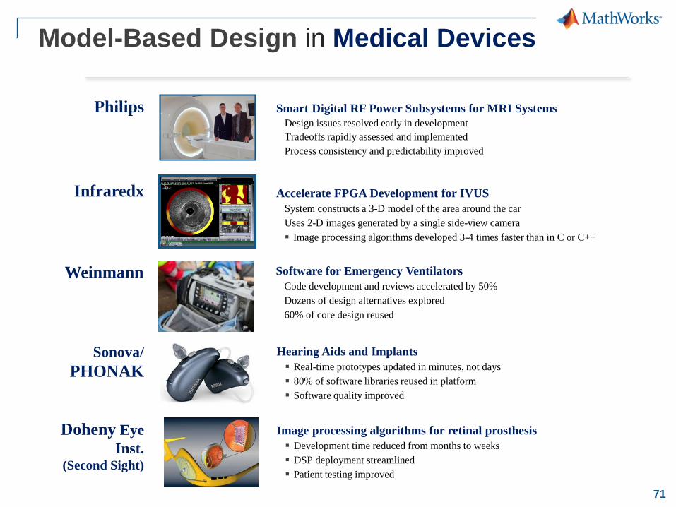
Model-Based Design in Medical Devices
Smart Digital RF Power Subsystems for MRI Systems
Design issues resolved early in development
Tradeoffs rapidly assessed and implemented
Process consistency and predictability improved
Accelerate FPGA Development for IVUS
System constructs a 3-D model of the area around the car
Uses 2-D images generated by a single side-view camera
Image processing algorithms developed 3-4 times faster than in C or C++
Software for Emergency Ventilators
Code development and reviews accelerated by 50%
Dozens of design alternatives explored
60% of core design reused
Image processing algorithms for retinal prosthesis
Development time reduced from months to weeks
DSP deployment streamlined
Patient testing improved
Hearing Aids and Implants
Real-time prototypes updated in minutes, not days
80% of software libraries reused in platform
Software quality improved
Philips
Infraredx
Weinmann
Sonova/
PHONAK
Doheny Eye
Inst.(Second Sight)
72
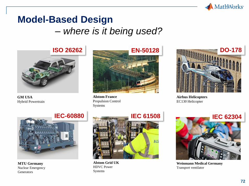
Model-Based Design
– where is it being used?
Weinmann Medical Germany
Transport ventilator
GM USA
Hybrid Powertrain
MTU GermanyNuclear Emergency
Generators
Alstom France
Propulsion Control
Systems
Alstom Grid UK
HDVC Power
Systems
Airbus Helicopters
EC130 Helicopter
EN-50128ISO 26262
IEC 61508 IEC 62304IEC-60880
DO-178
73
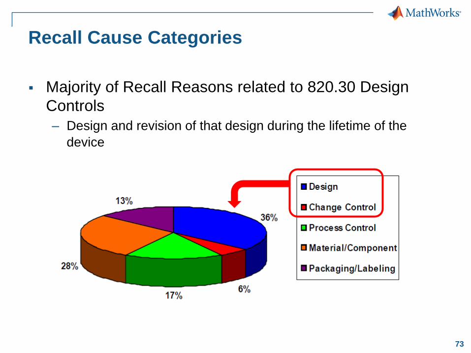
Recall Cause Categories
Majority of Recall Reasons related to 820.30 Design
Controls
– Design and revision of that design during the lifetime of the
device
74
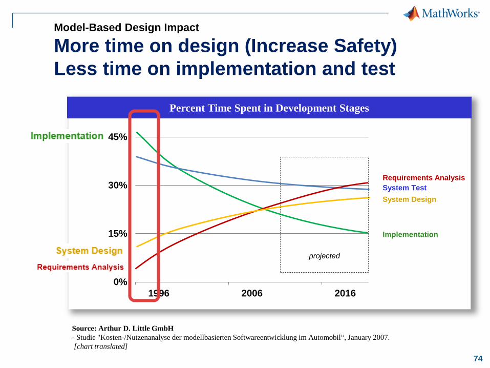
0%
15%
30%
45%
1996 2006 2016
System Test
Implementation
Requirements Analysis
System Design
Model-Based Design Impact
More time on design (Increase Safety)
Less time on implementation and test
Percent Time Spent in Development Stages
Source: Arthur D. Little GmbH
- Studie "Kosten-/Nutzenanalyse der modellbasierten Softwareentwicklung im Automobil“, January 2007.
[chart translated]
projected
75
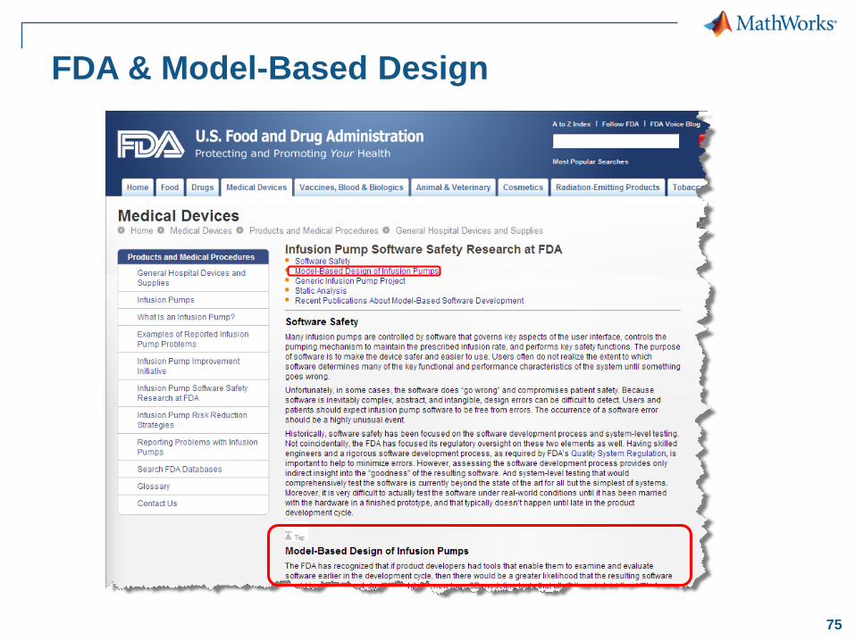
FDA & Model-Based Design
76
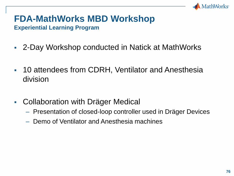
FDA-MathWorks MBD WorkshopExperiential Learning Program
2-Day Workshop conducted in Natick at MathWorks
10 attendees from CDRH, Ventilator and Anesthesia
division
Collaboration with Dräger Medical
– Presentation of closed-loop controller used in Dräger Devices
– Demo of Ventilator and Anesthesia machines
78
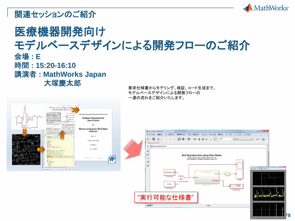
医療機器開発向けモデルベースデザインによる開発フローのご紹介会場 : E
時間 : 15:20-16:10
講演者 : MathWorks Japan
大塚慶太郎
関連セッションのご紹介
要求仕様書からモデリング、検証、コード生成まで、モデルベースデザインによる開発フローの一連の流れをご紹介いたします。
“実行可能な仕様書”

80
医療・介護機器の制御システム設計~ モデルベースデザインにトライ ~
コントローラ
制御 異常
停止
PID
PID
PID
アクチュエータ センサプラント
制御 電気 機械
+
-
人間
指令値 制御量
概要: ロボットアームのプラントモデリング、コントローラ設計講演者: 福井慶一セッション番号: E4
会場: E
時間: 16:20 – 17:10