Embed Size (px)
Citation preview

1
American Institute of Aeronautics and Astronautics
Improvements to the
Tendon-Actuated Lightweight In-Space MANipulator
(TALISMAN)
William R. Doggett1, John T. Dorsey2, Thomas C. Jones3, Kenneth N. Lodding4, George G. Ganoe5
NASA, Langley Research Center, Hampton, VA 23681, USA
David Mercer6
Stinger Ghaffarian Technologies, Hampton, VA 23681, USA
and
Bruce D. King7
Northrop Grumman, Hampton, VA 23681, USA
Devices for manipulating and precisely placing payloads are critical for efficient space
operations including berthing of spacecraft, in-space assembly, construction and repair. Key
to the success of many NASA space activities has been the availability of long-reach crane-like
devices such as the Shuttle Remote Manipulation System (SRMS) and the Space Station
Remote Manipulation System (SSRMS). These devices have been used for many operations
including berthing visiting spacecraft to the International Space Station, deployment of
spacecraft, space station assembly, astronaut positioning, payload transfer, and spacecraft
inspection prior to atmospheric re-entry. Retiring the Space Transportation System has led
to the removal of the SRMS from consideration for in-space missions, thus creating a
capability gap. Recognizing this gap, work was initiated at NASA on a new architecture for
long-reach space manipulators. Most current devices are constructed by joining revolute
joints with carbon composite tubes, with the joints accounting for the majority of the device
mass. For example in the case of the SRMS, the entire device mass is 410 kg (904 lbm); the
joint structure, motors, gear train, cabling, etc., accounts for the majority of the system mass
because the carbon composite tubes mass is 46 kg (101 lbm). An alternate space manipulator
concept, the Tendon-Actuated Lightweight In-Space MANipulator (TALISMAN) was created
to address deficiencies in the current state-of-the-art in long-reach manipulators. The
antagonistic tendon actuated joint architecture allows the motors actuating the joint to be
removed from the joint axis, which simplifies the joint design while simultaneously providing
mechanical advantage for the motors. The improved mechanical advantage, in turn, reduces
the size and power requirements for the motor and gear train. This paper will describe recent
architectural improvements to the TALISMAN design that: 1) improve the operational
robustness of the system by enabling maneuvers not originally possible by varying the
1 Research Engineer, Structural Mechanics and Concepts Branch, MS 190, Associate Fellow. 2 Senior Research Engineer, Structural Mechanics and Concepts Branch, MS 190, Senior Member. 3 Research Engineer, Structural Mechanics and Concepts Branch, MS 190, Member. 4 Computer Engineer, Flight Software Systems Branch, MS 472 5 Computer Engineer, Electromagnetics and Sensors Branch, MS 473. 6 Computer Engineer, Structural Mechanics and Concepts Branch, MS 190. 7 Senior Designer, Aeronautics Systems Engineering Branch, MS 238.
2
American Institute of Aeronautics and Astronautics
TALISMAN geometry; 2) enable efficient active antagonistic control of a joint while sharing
cable between antagonistic tension networks; and 3) uses a unique arrangement of differential
capstans to reduce motor torque requirements by an order of magnitude. The paper will also
summarize recent efforts to enable autonomous deployment of a TALISMAN including the
deployment concept of operations and associated hardware system design. The deployment
forces are provided by the same motor systems that are used for articulation, thus reducing
the mass associated with the deployment system. The deployment approach is being tested on
a TALISMAN prototype which is designed to provide the same operational performance as a
shuttle-class manipulator. The prototype has been fabricated and is operational in a new
facility at NASA Langley Research Center that has a large area (15.2 m by 21.3 m [50 ft by 70
ft]) air-bearing floor.
Nomenclature and Acronyms
CL = length of the lower cable
CU = length of the upper cable
DCM = distance on cable management side
DWL = distance on working load side
L = link length
R = radius
RL = large capstan radius
RS = small capstan radius
S = spreader length
SOA = state-of-the-art
SRMS = Shuttle Remote Manipulation System
SSRMS = Space Station Remote Manipulation System
TALISMAN = Tension Actuated In Space MANipulator
TH = torque at the handle
W = weight
I. Introduction
he Tension Actuated In Space MANipulator (TALISMAN) created a new structural architecture for long-reach
manipulators. This long reach arm uses a series of tension members (often cables) for both structural stiffening
as well as joint actuation.1,2 This unique arrangement of tension elements simultaneously provides improved structural
performance and improved mechanical advantage for the motors. Compared to state-of-the-art (SOA) long-reach in-
space manipulators, such as the Shuttle Remote Manipulator System (SRMS) and the Space Station Remote
Manipulator System (SSRMS), a TALISMAN-based manipulator with equivalent stiffness in the plane of the cables
provides an order of magnitude reduction in mass and nearly an order-of-magnitude reduction in packaging volume.3,4
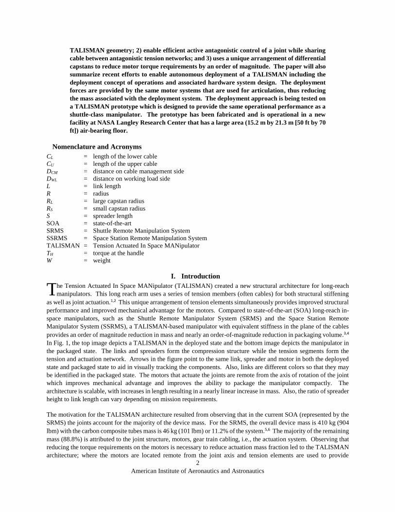
In Fig. 1, the top image depicts a TALISMAN in the deployed state and the bottom image depicts the manipulator in
the packaged state. The links and spreaders form the compression structure while the tension segments form the
tension and actuation network. Arrows in the figure point to the same link, spreader and motor in both the deployed
state and packaged state to aid in visually tracking the components. Also, links are different colors so that they may
be identified in the packaged state. The motors that actuate the joints are remote from the axis of rotation of the joint
which improves mechanical advantage and improves the ability to package the manipulator compactly. The
architecture is scalable, with increases in length resulting in a nearly linear increase in mass. Also, the ratio of spreader
height to link length can vary depending on mission requirements.
The motivation for the TALISMAN architecture resulted from observing that in the current SOA (represented by the
SRMS) the joints account for the majority of the device mass. For the SRMS, the overall device mass is 410 kg (904
lbm) with the carbon composite tubes mass is 46 kg (101 lbm) or 11.2% of the system.5,6 The majority of the remaining
mass (88.8%) is attributed to the joint structure, motors, gear train cabling, i.e., the actuation system. Observing that
reducing the torque requirements on the motors is necessary to reduce actuation mass fraction led to the TALISMAN
architecture; where the motors are located remote from the joint axis and tension elements are used to provide
T

3
American Institute of Aeronautics and Astronautics
significant mechanical advantage about the joint axis. The tension elements are also designed to provide link
stiffening. This increased structural stiffening is analogous to that realized in bridge design as shown in Fig. 2. For
moderate spans, beams are used to support a roadway (Fig. 2a), but for larger spans (Fig. 2b) tension supported spans
are used because of their improved structural efficiency. Similarly, SOA in-space robotic manipulators, such as SRMS
and SSRMS, are constructed by joining revolute joints with efficient carbon composite tubes (Fig. 2c), however the
TALISMAN uses a tension stiffened architecture (Fig. 2d), resulting in reduced mass and stowed volume for the
manipulator. In addition, placing the motors remotely from the joint axis overcomes significant shortcomings of the
current SOA, including the need to generate large torques over small distances, which results in large and massive
gear train/motor combinations. The motor location remote from the joint axis in the TALISMAN architecture also
alleviates crowding near the joint axis where joint articulations, gearing and motors, along with the associated
electronics and cable harnesses are all vying for space in the SOA systems.7
In this paper, three significant improvements to the TALISMAN architecture are disclosed. The first is the ability to
actively change the geometry of the TALISMAN components during operation. This important capability allows the
device geometry to vary to avoid obstacles, change mechanical stiffness or change actuator authority, or to optimize
performance for a specific maneuver. The second significant improvement disclosed here is an arrangement of
capstans that enable each tension segment to be actively controlled while using one or two tension elements per joint.
The tension element or cable circulates from one side of the link to the other side during operation as the joint
articulates and this can be accomplished with multiple capstans on a single cable without having springs in the load
path. The third significant improvement is a unique cable arrangement that uses a pair of differential capstans to
reduce the torque required by the motor by over an order of magnitude. This improvement directly reduces the mass
and power requirements of the motor, brake and gear train.
A recent focus has been to enable autonomous deployment of a TALISMAN. The resulting hardware design not only
enables efficient deployment, it provides the ability to move the spreader from one side to another during operation,
i.e., reconfigure dynamically for specific maneuvers. The hardware system has been fabricated and is undergoing
testing using a TALISMAN prototype designed to provide the same operational performance as a shuttle-class
manipulator. The device is being tested in a new facility at NASA Langley Research Center that has a large area, 15.2
m by 21.3 m (50 ft by 70 ft), air-bearing floor.
Figure 1. TALISMAN in the packaged and deployed configurations.
Motor, Gear
Brake Unit
Tension
Segment Spreader Link
Joint Deployed
Packaged

4
American Institute of Aeronautics and Astronautics
II. Variable Geometry for Obstacle Avoidance and Performance Optimization
The first improvement described is the ability to reconfigure the geometry of TALISMAN components during
operation which will be described using a simplified TALISMAN joint system depicted in Fig. 3, where the motors
Figure 3. TALISMAN based joint illustrating
two methods to reconfigure geometry.
Spreader
Discrete
Stops
Telescoping
Link Outer Link
Section
Inner Link
Section
Joint Axis of
Rotation
Cable Management
Spring
Capstan
Tension
Member
Credit: Carol M. Highsmith Archive,
Lib. of Congress, Prints & Photo. Div. Credit: Dog River Bridge, AL NOAA
c. SSRMS, beams connect joints d. TALISMAN, Tension structure supports joints.
Figure 2. Comparison of beam and tension supported structures.
a. Beam-supported bridge span b. Tension-supported bridge span

5
American Institute of Aeronautics and Astronautics
have been omitted to enable the cable routing to be visible. The capability to change geometry enables both compact
packaging for launch and improved operational versatility and performance, including the ability to reconfigure to 1)
avoid obstacles during operation, 2) increase stiffness, and 3) improve actuator control authority. The key features of
a TALISMAN joint are 1) the compression members (i.e., the links and spreaders), 2) the tension members, 3) the
joint axis of rotation, 4) the capstans, and 5) the cable management spring as shown in Fig. 3. Here, the tension
element will be referred to as a cable for simplicity, but the element may be a cable, rope, tape, or combination of
these and rigid elements. There are many possible methods to reconfigure the geometry of TALISMAN components,
two methods will be described here. The first method to reconfigure the geometry of the links is to change the link
length; for example the overall link length can be shortened. In Fig. 4, one possible length changing method,
telescoping sections, is illustrated, where the outboard grey sections are telescoped into the inboard orange sections.
The links are shown in Fig. 4a fully extended while the links are shown in Fig. 4b retracted. Although both links are
shown retracted in Fig. 4b, it is possible to only telescope one link depending on requirements of the task.
It is also possible to change the geometry of the spreader. In the simplified joint shown in Fig. 3, a monolithic spreader
is used, i.e., a single fixed-length component forms the spreader for the joint. The spreader could be composed of
Figure 5. TALISMAN spreader reconfiguration.
a. Spreader centered b. Spreader offset
Lower
Cables
Upper
Cables
Stops
Figure 4. TALISMAN link telescoping.
a. Links extended b. Links retracted

6
American Institute of Aeronautics and Astronautics
multiple components, each of which may be deployable, enabling one side of the tension network (above the links for
example) to change independently of the other side of the tension network (below the links). For simplicity, in the
current description, three discrete stops in a fixed-length spreader are identified. The black pin at the center of the
joint can release and reengage the spreader, at a different stop location, enabling the spreader to change location
relative to the joint axis of rotation, as shown in Fig. 5b. In Fig. 5a, the spreader is centered relative to the axis of
rotation of the joint, while in Fig. 5b the spreader has been repositioned upward.
An important feature of the TALISMAN architecture is that the spreader reconfiguration shown in Figs. 4 and 5 can
be accomplished using the link articulation motors. By varying the tension in the cables or the angle of action of the
tension cables, the spreader can be repositioned from one side to the other by simply releasing and reengaging a
locking pin. Relaxing the tension in the upper cables and increasing the tension in the lower cables for the
configuration shown in Fig. 5a, then releasing the pin will cause the spreader to move to the position shown in Fig.
5b. Although this is a dynamic event; as the spreader is moving, the joint is articulating; with proper control, the
maneuver is straight forward. Likewise, the telescoping action shown in Fig. 4 can be accomplished using the link
articulation motors. Retracting the outer link section is straight forward, accomplished by increasing the tension in
the appropriate cables. Extending the outer links is accomplished by reacting against a temporary anchorage, as shown
in Fig. 6, or by swinging the link rapidly enough to generate sufficient outward dynamically induced force to allow
the outer link to be released and then re-engaged in the extended position. One of many possible maneuvers to extend
the last outboard link (the link between the distal joint and wrist) using a temporary anchor location is depicted in Fig.
6. In this example, the wrist connects to an anchor location and then the proximal joint rotates clockwise while the
distal joint rotates counter clockwise as shown, which extends the last link. As has been shown, it is possible to
reposition the spreader, as well as extend and retract links using only the motors required for articulating the
Figure 6. Method to extend TALISMAN link.
Base Connection Temporary Anchorage
Metacarpo Joint
Extend
Link
Proximal Joint
Distal Joint
Base Joint Wrist

7
American Institute of Aeronautics and Astronautics
TALISMAN. Other schemes to change manipulator geometry are possible, including schemes that use additional
motors or actuators to actively drive the links and spreaders to different configurations. However, there is a mass
penalty associated with implementing these active approaches. Although multiple motors per joint are shown in Fig.
1, the versatility of the TALISMAN architecture makes it also possible to perform the maneuvers described here using
a single motor per joint.
III. Antagonistic Capstan Drive without Springs in the Load Path for Joint Control
The second innovation disclosed here is a unique arrangement of capstans and springs that provides the ability to
actively control the joint articulation, i.e., the relationship between the spreader and link, in an antagonistic
arrangement without the springs being in the load path. This antagonistic arrangement of tension elements is similar
to the arrangement of muscles in a human finger. A capstan works in conjunction with a running element, referred to
as a cable here, which enters and exits the capstan after a few wraps. Friction between the cable and capstan prevents
the cable from rotationally slipping on the capstan and enables the capstan to transfer load to the cable while drawing
the cable in. Unlike a pulley, the load on the input and exit side of a capstan is different. A significant difference
between a capstan and a hoist is that a hoist or winch system uses a drum, where excess cable builds up on the drum,
which increases the effective drum diameter as cable is drawn in. Here, the term capstan and cable will be used, as
these are familiar terms, although capstans can also be used with tapes. Springs are one means to accommodate the
unequal change in length of the cables on each side of the joint during articulation as well as to maintain a small exit
tension on the capstans. With this unique capstan arrangement, a continuous cable network can be used that circulates
cable from one side of the link to the other, significantly reducing the total cable required to actuate a joint in the
TALISMAN architecture, as shown in Figs. 7 and 8. In the figures, the motors driving the capstans and the capstan
mounting hardware have been hidden for clarity. Also, the capstans are shown with different diameters to make it
clear that there are two independent capstans. In practice, the capstans can have the same diameter or different
diameters, depending on the results of optimizing the TALISMAN for a particular mission. The flow of a single cable
is shown in Fig. 7 using the red arrows. Starting at the entry of the lower cable section as the cable enters the link, the
cable passes around the larger green capstan one full revolution then proceeds from the top of the larger capstan to the
cable management pulley, which is attached to the cable management spring on the right of the figure. The cable
Figure 7. Antagonistic capstan
arrangement side view.
Link
Lower Cable
Section
Upper Cable
Section
Capstan
Cable Management
Spring
Cable Management
Pulley

8
American Institute of Aeronautics and Astronautics
continues to the bottom of the small orange capstan and passes one full revolution around the small capstan before
exiting through the top of the link (identified as the upper cable section in the figure). Capstans, unlike pulleys, enable
there to be different tension forces on the cable entering and leaving the capstan. Thus, the cable management spring
shown in the figures is only required to provide a small force to ensure that the cable remains in contact with the
capstan. Because the force required from the spring is small, the spring can have a much smaller stiffness and thus is
less massive than if it had to be included in the tension load path. Further, because the spring is not in the tension load
path, the spring does not affect the fundamental frequency of the joint and the fundamental frequency of the joint can
be tuned by varying the preload in the cables, with the spring arrangement managing the excess cable. A view of this
arrangement looking out from the joint past the cable management pulley toward the capstans is shown in Fig. 8. By
having the lower and upper cable sections enter and exit the system near the centerline of the link, this position
minimizes the torque exerted on the link from the offset in these elements.
IV. Differential Capstans to Reduce Required Motor Torque
Cranes used for lifting objects use cable systems where the cable is driven by a large hoist
system that takes up and wraps cable on a drum and reels the cable out to effect motion of the
lifting hook. As shown in the simplified image of Fig. 9, the load from the cable must be
reacted by the hoist system. This reaction torque directly affects the hoist motor and drive
system as well as the brake system used to arrest hoist motion. The focus here is on reducing
the reaction torque, TH, caused by the load since this affects motor, gearbox, and brake sizing.
Although present, bearing loads at the supports for the rotating elements will not be discussed.
In general, the bearing loads for the differential capstan system are similar to those found in a
traditional system such as depicted in Fig. 9. The motor torque acts to drive the capstan or
hoist and is directly proportional to the torque required to turn a handle affixed to the hoist
drum or capstan. The torque at the handle of Fig. 9 is given by
RWTH (1)
where TH is the handle torque, W is the lifted weight and R is the radius of the hoist drum. A significant improvement
on this system is obtained using a differential windlass (also called Chinese windlass), as shown in Fig. 10. In this
design, the torque applied to the handle, TH, is proportional to the difference in the torques exerted by each line;
SLH RRW
T 2
(2)
TH R
Figure 9.
Simple hoist.
W
Figure 8. Antagonistic capstan arrangement,
looking from joint towards capstan.
Link
Lower Cable
Section
Upper Cable
Section
Capstan Cable Management
Pulley

9
American Institute of Aeronautics and Astronautics
where W is the weight being lifted, RL is the radius of
the larger drum, and Rs is the radius of the smaller drum.
A close up of the two coupled drums is shown in Fig.
10b. As the handle is turned clockwise, cable is fed off
the smaller diameter drum and taken up on the larger
diameter drum. Because the larger drum has a larger
circumference, more cable is taken up than released and
the hook is raised. A single cable is used, and the red
arrows in the figure indicate the path of the cable about
the individual drums. The ratio of these drum diameters
provides a gear ratio between turns of the handle and
raising or lowering of the hook. The major drawback to
this arrangement is that as the drum diameters become
nearly equal, improving the mechanical advantage, the
amount of cable that must be stored on the drums
becomes large causing cable management difficulties,
and an increase in mass.
In contrast to this traditional approach, a novel
arrangement of differential capstans to react the load
created by the lifting hook is described (see Fig. 11). As with the
differential windlass, the torque required to lift the load is proportional
to the difference between the radii of the two capstans. This
arrangement has other advantages including; 1) the ability to tune the
system gear ratio by varying the ratio of capstan diameters, 2) cable
enters and exits the capstan so the cable does not accumulate on the
drum hence, the relationship between capstan rotational speed and cable
speed does not change, and 3) wear on the cable is reduced because the
cable does not over wrap on itself. Referring to Fig. 11, the part of the
mechanism above the differential capstans is the cable management side
of the device, including the tension spring and cable management
pulley. The portion below the differential capstans is the load side of
the mechanism, including the load pulley, load hook, and working load,
W. A drawback to the proposed system is that the cable travels a greater
distance, circulating in a loop around the cable management pulley and
load pulley, making management of the extra cable as the hook is raised
more challenging. As the working load is raised, the distance from the
capstan axis to the load pulley, DWL, decreases and the distance from the
capstan axis to the cable management pulley, DCM, increases (in the
figure, this motion is proportional). Because of the unique architecture
of the TALISMAN, the cable management issue is minimized by
sharing the same cable between two tension networks.
The use of capstans, as shown in Fig. 11, reduces the total amount of
cable needed, but requires that the cable circulate. In addition, the length
of cable on the cable management side, i.e., the take up side, is
proportional to the length of cable on the load side. In other words, as
the hook is lifted the excess cable circulates around the differential
capstans and is taken up by the tension element, the spring in the figure.
Thus, without additional elements such as block and tackles, the tension
element travel must equal that of the load. However, the unique
Cable
Management
Side
Differential
Capstans
Load
Side
Hook
Working
Load W
Figure 11. Differential
capstan arrangement.
DWL
DCM
TH
Tension
Spring
Cable
Management
Pulley
Load
Pulley
TH
Figure 10. Differential
windlass.
RL
RS
W
2 W
2
b. Close up of windlass drums
W
a. Overview

10
American Institute of Aeronautics and Astronautics
TALISMAN architecture makes nearly full use of all the cable at all times by sharing the cable between a pair of
antagonistic tension loops above and below the link, as will be illustrated using the joint postions shown in Fig. 12,
where S is the spreader height, L is the link length, CU is the upper cable length, CL is the lower cable length. The load
side of Fig. 11 is the portion from the spreader to the capstan identified in Fig. 12, with one tension loop above the
link and one tension loop below the link. The cable management side of Fig. 11 is shared between the two tension
loops and occurs inside the link as identified in Fig. 12. For simplicity, let S = L. With the joint in the configuration
shown in Fig. 12a, the total cable length, CU + CL = 2 √2 L = 2.82 L, where in Fig. 12b with the joint articulated 60°,
CU + CL = L+√3L = 2.732 L, a change of 3 percent of the original cable length, which is managed by the cable
management pulley and spring shown in the figure.
V. Deployment System for TALISMAN
A recent focus has been on enabling the efficient transition from the packaged state to the deployed state (see Fig. 1).
This deployment process uses the same motors as are used for joint articulation, which reduces the complexity and
parasitic mass of the deployment system. The general deployment scheme is depicted in Fig. 13, where the joint
begins in the packaged state (Fig. 13a) and unfurls to the extended state (Fig. 13c). The joint unfurls because the
cables pass along the outside of the links creating an offset (Fig. 13b) about the joint axis, so that when the cables are
placed in tension, a torque is generated about the joint axis causing the joint to unfurl and open to the extended position.
After the joint is in the extended configuration, the spreader is released (by retracting pins) allowing the spreader to
translate to the deployed position (Fig. 13d). The pins are spring loaded to extend into machined holes enabling
discrete repositioning of the spreader. A photograph of the hardware used in the test is shown in Fig. 14 and is also
shown undergoing a test in the facility shown in Fig. 15. The assembled spreader with the pin retraction motor
mounted is shown in Fig. 14a. The pin retraction motor disengages pins to releases the spreader, which allows it to
translate. A close up of the pin retraction motor and associated hardware which form a motorized turnbuckle is shown
in Fig. 14b, that when activated retract a pair of pins, one on each rail, to allow the spreader to move. This system
supports both deployment and dynamic reconfiguration during operation. The test facility shown in Fig. 15 includes
a precision poured concrete floor that provides a 15.2 m by 21.3 m (50 ft by 70 ft) surface suitable for air-bearing
operation. The blue cylinders located under the joints and at the wrist, one of which is identified in the photograph,
are air bearings which float on a cushion of air. The air bearings float the manipulator to simulate zero-g operations
in the plane of the floor.
The two TALISMANs shown in Fig. 15 were designed to have the same reach and in-plane stiffness as the SRMS.
The resulting manipulator is 15.2 m (50 ft) long, has four links, and is shown in Fig. 1. To enable dual arm operation
within the facility, the last link of the TALISMANs were removed to shorten them to approximately 11.6 m (38 ft) in
length as shown in the photograph. The TALISMANs are secured to a versatile base structure enabling the distance
S
60
CL
CU
L
CU Cable Management
Pulley and Spring
Load
Side
Cable
Management
Side
Figure 12. Sharing cable between
antagonist tension elements.
a. Joint straight b. Joint angled to 60°
CL

11
American Institute of Aeronautics and Astronautics
between the manipulator bases and the angle of the base spreader to be easily adjusted so that a variety of potential
spacecraft attachment schemes can be quickly evaluated.
VI. Summary and Concluding Remarks
The Tendon-Actuated Lightweight In-Space MANipulator (TALISMAN) represents a novel new architecture for
long-reach space manipulators. The antagonistic tendon actuated joint architecture allows the motors actuating the
joint to be located remote from the joint axis, which simplifies the joint design, while simultaneously providing
mechanical advantage for the motors and structural stiffening of the joints and links. The improved mechanical
advantage for the motors, in turn, reduces the size and power requirements for the motor and gear train. This paper
Figure 15. Multi-arm testbed in
new flat floor facility.
Air Bearing
Figure 13. Single joint
deployment sequence.
a. Packaged
c. Extended
d. Deployed
b. Cable Detail
Joint Axis
Figure 14. Deployment test
hardware.
a. Deployment
spreader b. Pin retraction
motor
Pin Retraction
Motor
Locking Pins

12
American Institute of Aeronautics and Astronautics
described recent significant architectural improvements to the TALISMAN design that 1) improve the operational
robustness of the system by enabling a manipulator to reconfigure geometrically to avoid obstacles or tune the
manipulator performance for specific maneuvers, 2) enable efficient active antagonistic control of a joint while sharing
cable between two antagonistic tension networks, and 3) uses a unique arrangement of differential capstans to reduce
motor torque requirements by an order of magnitude.
Recently, efforts have focused on enabling autonomous deployment of a TALISMAN. The deployment mechanism
design and the associated hardware system that was fabricated were described. Deployment forces are provided by
the same motor systems that are used for articulation in an effort to reduce the mass and complexity associated with
the deployment system. The deployment approach is undergoing tests on a TALISMAN prototype which is designed
to provide the same operational performance as a shuttle-class manipulator. Two TALISMAN prototypes have been
fabricated and are operational in a new facility at NASA Langley Research Center that has a large area (15.2 m by
21.3 m [50 ft by 70 ft]) air-bearing floor suitable for simulating zero-g operations.
1 Doggett, W. R., Dorsey, J. T., Collins, T. J., King, B. D., and Mikulas, M. M., “A Versatile Lifting Device for
Lunar Surface Payload Handling, Inspection and Regolith Transport Operations,” Proceedings of the Space
Technology and Applications International Forum – 2008 (STAIF-2008), February 10–14, 2008, Albuquerque, NM. 2 Mikulas, M. M., Yang, L. F., “Conceptual Design of a Multiple Cable Crane for Planetary Surface Operations,”
NASA TM-104041, January, 1991. 3 Patten, L., Evans, L., Oshinowo, L., Ochisor, M., Kazuharu, N., Lodewijk, A., Tabarah E., “International Space
Station Robotics: A Comparative Study of ERA, JEMRMS and MSS,” 7th ESA Workshop on Advanced Space
Technologies for Robotics and Automation, ASTRA 2002' ESTEC, Noordwijk, The Netherlands, November 19 -
21, 2002. 4 Doggett, W. R., Dorsey, J. T., Jones, T. C., King, B. D., “Development of a Tendon-Actuated Lightweight In-
Space MANipulator (TALISMAN),” Proceedings of the 42nd Aerospace Mechanisms Symposium, Baltimore, MD,
2014. 5 Dunbar, D. R., Robertson, A. R., and Kerrison, R. “Graphite/Epoxy Booms for the Space Shuttle Remote
Manipulator.” International Conference on Composite Materials, Toronto. 1978. 6 Kumar, P., Truss, P., and Wagner-Bartak, C. G. “System Design Features of the Space Shuttle Remote
Manipulator.” Proceedings of the Fifth World Congress on Theory of Machines and Mechanisms. 1979. 7 Craig, John J. Introduction to Robotics Mechanics and Control, 2nd Ed. Addison-Wesley Publishing Co., New
York, NY, 1989.
References