Embed Size (px)
Citation preview

BRIDGE REHABILITATION PLANS
BRIDGE FILE
PROJECT NO. 0200636
BRIDGE FILE
PROJECT LOCATION SHOWN BY
SHEETS
PROJECT
SURVEY BOOK
CONTRACT
of
A.A.D.T.
A.A.D.T.
DIRECTIONAL DISTRIBUTION
TRUCKS
DESIGN SPEED
PROJECT DESIGN CRITERIA
FUNCTIONAL CLASSIFICATION
RURAL/URBAN
TERRAIN
ACCESS CONTROL
V.P.D.
V.P.D.
%
TRAFFIC DATA
DESIGN DATA
PROJECT DESIGNATION
CONTRACT
INDIANA DEPARTMENT
OF TRANSPORTATION
( )
( )
A.A.D.T.%
APPROVED
FOR LETTING:
DATE
PHONE NUMBER
PLANS
PREPARED BY:
DATE
CERTIFIED BY:
LATITUDE: 37°55'47" N. LONGITUDE: 87°32'54" W.
50 M.P.H.
FOR SPANS OVER 20 FEET
INDIANA DEPARTMENT OF TRANSPORTATION
STRUCTURE INFORMATION
STRUCTURE TYPE SPAN AND SKEW OVER STATION
SCALE: 1" = 1000'
INTERSTATE
69
VICINITY MAP
VANDERBURGH COUNTY
OHIO RIVER OVERFLOW
NB STRUCTURE: 041-82-4998C
INDIANA DEPARTMENT OF TRANSPORTATION STANDARD
SPECIFICATIONS DATED 2016 TO BE USED WITH THESE PLANS.
1@85'-3"
3@86'-0
1@43'0"
NO SKEW
041-82-4998C
℄ STRUCTURE
STA. 160+18.35
DECK RECONSTRUCTION ON STRUCTURE 041-82-4998-C (NB), U.S. 41 OVER OHIO RIVER OVERFLOW LOCATED
APPROXIMATELY 0.82 MILES SOUTH OF THE U.S. 41 AND I-69 INTERCHANGE, IN SECTIONS 8 AND 9, TOWNSHIP 7
SOUTH, RANGE 10 WEST, VANDERBURGH COUNTY, INDIANA.
BUILT-UP STEEL
PLATE GIRDER
BRIDGE
2601 Fortune Circle East | Suite 202B | Indianapolis, IN 46241
P 317.243.9800 | F 317.243.9100 | www.infrastructure-eng.com
ENGINEERING INCORPORATED
02006360200636
B-33539 041-82-4998C
U.S. 41 NB OVER OHIO RIVER OVERFLOW
VANDERBURGH COUNTY
VINCENNES DISTRICT
Infrastructure Engineering, Inc. (317) 243-9800
041-82-4998C
DESIGNATION
0200636
1
0200636B-33539
2013
2017
19989
20380
100
11.6
3R NON-FREEWAY
PRINCIPAL ARTERIAL
URBAN
LEVEL
NONE
R. 10 W.
T. 7 S.
H.U.C. = 05140202010020
R.P. 0+43
31
FULL SIZE PLANS HAVE BEEN PREPARED USING
STANDARD ENGINEERING SCALES, REDUCED SIZED
PLANS WILL NOT CONFORM TO STANDARD RULES.
8
9
C
H
E
A
T
A
M
S
L
O
U
G
H
O A
A
AT
I
N TF T R N S PO
RT
AT
ION
NA
DE
PR
ME
ND I
NOTE: SEE ROAD PLANS FOR REMOVAL OF EXISTING GUARDRAIL,
PROPOSED GUARDRAIL, PAVEMENT MARKINGS, EROSION
CONTROL MEASURES AND MAINTENANCE OF TRAFFIC
DETAILS.
A.A.D.T. ( )2037 V.P.D.25630
10/31/2016
DRAFT
Not for C
onstructio
n

UTILITIES
DRAWINGS INDEXSHEET NO.
INDEX
1
2 INDEX
3
4
TYPICAL SECTIONS5 - 6
GENERAL PLAN EXISTING STRUCTURE
7 - 11
GENERAL PLAN PLANNING STRUCTURE
12 - 14
PEDESTAL DETAILS - NORTHBOUND STRUCTURE15 - 16
TITLE
INDEX
SHEET NO. DATEREVISED
REVISIONS
DESIGN ENGINEER DATE
RECOMMENDED
FOR APPROVAL
DESIGNED:
CHECKED:
DRAWN:
CHECKED:
HORIZONTAL SCALE
VERTICAL SCALE
SURVEY BOOK
CONTRACT PROJECT
of
SHEET
DESIGNATION
BRIDGE FILE
INDIANA
DEPARTMENT OF TRANSPORTATION
B-33539
041-82-4998C
0200636
0200636
AS NOTED
AS NOTED
EAS
NDB
GSB
NDB
31
10/31/2016
BENT NO. 1 DETAILS - NORTHBOUND STRUCTURE
BENT NO. 6 DETAILS - NORTHBOUND STRUCTURE
PIER NO. 5 DETAILS NORTHBOUND STRUCTURE17 - 18
STRUCTURAL STEEL DETAILS - NORTHBOUND STRUCTURE19 - 23
FLOOR DETAILS - NORTHBOUND STRUCTURE24 - 29
APPROACH SLAB DETAILS - NORTHBOUND STRUCTURE30
BRIDGE SUMMARY31
2
COMMUNICATIONS: AT&T
134 NW Sixth Street
Evansville, Indiana 47708
ATTN: Marc Clark
P. (812) 464-6050
AT&T
134 NW Sixth Street
Evansville, Indiana 47708
ATTN: Andy Folz
P. (812) 464-6055
WINDSTREAM COMMUNICATIONS
5020 Smyth Drive
Evansville, Indiana 47715
ATTN: Daniel Leskinen
P. (812) 759-2833
P. (812) 455-9558 (CELL)
TIME WARNER CABLE
1900 N, Fares Avenue
Evansville, Indiana 47711
ATTN: Daryl Hulsey
P. (812) 253-2755
P. (812) 305-8348 (CELL)
ELECTRIC: KENERGY CORPORATION
ATTN: Kyle Hart
P. (270) 8314602
VECTREN
Jody Chapman
1 North Main Street
Evansville, Indiana 47711
INDOT SIGNALS & LIGHTING
ATTN: Robert Horton
P. (812) 699-0643
P. (812) 698-4743 (CELL)
ITS TECHNOLOGY
ATTN: Konstantin Veygman
P. (317) 899-8606
WEIGHT STATION JACK MANN SCALES, INC.
2073 MercerRoad
Lexington, Kentucky 40511
ATTN: Larry Stagner
E. larry@ jackmannscales.com
P. (859) 233-0322
KYTC
ATTN: David Cornett
P. (502) 564-4556
DRAFT
Not for C
onstructio
n

L86'-0" ℄ Pier to ℄ Pier 86'-0" ℄ Pier to ℄ Pier L
Lane
Lane
Lane
Lane
20'-6" Conc.
Appr. Slab
(Typ.)
1'-0" Pvmt.
Ledge, Mudwall
6" Pvmt.
Ledge
387'-9" Out to Out of Bridge Floor
53'-6" O
ut to O
ut of Copings
51'-0" Clear Roadw
ay
12'-0"
12'-0"
12'-0"
4'-0"
3'-0" 3'-0" 2'-0" 2'-0" 3'-0" 2'-6"
1'-3"
1'-3"
9
0
º
0
'
0
"
12'-0"
12'-0"
12'-0"
40'-3" Clear Span
Flow
OH
IO
RIVER
OVERFLO
W
"A"
"A"
PLAN
NORTHBOUND STRUCTURE
ELEVATION
NORTHBOUND STRUCTURE
4'-0"
Scale:
1
16
"= 1'-0"
Scale:
1
16
"= 1'-0"
Note: Hatched Areas indicate Portions
to be Removed.
BENT NO.1
PIER NO.2 PIER NO.3 PIER NO.4 PIER NO.5
BENT NO.6
SPAN "A" SPAN "B" SPAN "C" SPAN "D"SPAN "E"
FIXED
FIXED FIXEDEXP.EXP.EXP.EXP.
STRUCTURE IS BUILT ON A +0.20% GRADE
CONTINUOUS WELDED STEEL PLATE GIRDER AND R.C. GIRDER BRIDGE
85'-3" ℄ Pier to ℄ Top Shoe
5 SPANS: 1 AT 85'-3", 2 AT 86'-0", 1 AT 85'-3" AND 1 AT 40'-3",NO SKEW,
51'-0" CLEAR ROADWAY ON U.S. 41 NB OVER OHIO RIVER OVERFLOW
NOTES
Lane
L L
37'-0"
Lane
See Sheet 4 for Proposed Structure General Plan.
See Sheet 6 for Existing Section "A-A"
85'-3" ℄ Top of Shoe to ℄ Top Shoe
2'-3" ℄ Top of Shoe to Clear Span
1'-6"
1'-3"
℄ Bent No. 1
Sta. 158+25.10
P.G. El. 381.61
Shoulder Line
Shoulder Line
Remove Concrete Approach Slab
(Typ.)
2" Ø Steel Conduit
in Coping
PGL NB Lanes
Coping Line
Face of Railing
Face of Railing
Coping Line
℄ Median
Shoulder Line
Shoulder Line
Remove Bridge Deck
Remove Existing
Class S-S
Exp. Joint
Existing Piles
to Remain (Typ.)
Remove Existing Wingwalls,
Remove Portions of End Bent
and Remove Existing Bearing Plates
Remove Bridge RaiL (Type 5A)
and Bridge Deck (Typ.)
Jack and Support Existing
Steel Beams and Remove
Steel Bearing Assemblies
(Typ. At All Bents and Piers)
Remove Portion of Existing Steel
Beams in Span "D"
Remove Existing S-S Expansion Joint
Remove Pier Cap
on Pier No. 5
Remove Existing Reinforced
Concrete Girders Remove Existing Wingwalls
Remove Existing
End Bent
℄ Pier No. 2
Sta. 159+10.60
P.G. El. 381.78
℄ Pier No. 3
Sta. 159+96.60
P.G. El. 381.95
℄ Pier No. 4
Sta. 160+82.60
P.G. El. 382.13
℄ Pier No. 5
Sta. 161+68.60
P.G. El. 382.30
℄ Bent No. 6
Sta. 162+11.60
P.G. El. 382.38
℄ Structure
Sta. 160+18.35
P.G. El. 382.00
EXISTING SPLICE
PLATE (Typ.)
Low Structure El. 375.81
Remove Existing
Guardrail (Typ.)
(See Road Plans)
℄ Structure
8'-6"
US 41 NB STRUCTURE
Remove Existing Light
Standard (Typ.)
Remove Existing Light
Standard (Typ.)
Note: See Road Plans for Removal of Existing Guardrail,
Proposed Guardrail, Pavement Markings, Erosion
Control Measures and Maintenance of Traffic Details.
DESIGN ENGINEER DATE
RECOMMENDED
FOR APPROVAL
DESIGNED:
CHECKED:
DRAWN:
CHECKED:
HORIZONTAL SCALE
VERTICAL SCALE
SURVEY BOOK
CONTRACT PROJECT
of
SHEET
DESIGNATION
BRIDGE FILE
INDIANA
DEPARTMENT OF TRANSPORTATION
B-33539
041-82-4998C
0200636
0200636
AS NOTED
AS NOTED
EAS
NDB
GSB
NDB
31
10/31/2016
3GENERAL PLAN
EXISTING STRUCTURE
DRAFT
Not for C
onstructio
n

86'-0" ℄ Pier to ℄ Pier 86'-0" ℄ Pier to ℄ Pier
Lane
Lane
Appr. Slab
(Typ.)
9" Pvmt. Ledge
(Typ.) Ledge
9" Pvmt.
388'-0" Out to Out of Bridge Floor
50'-6" Clear Roadw
ay
12'-0"
12'-0"
12'-0"
3'-0" Bent 3'-0" Pier 2'-0" Pier 2'-0" Pier
3'-0" Pier Cap
3'-0"
1'-6"
1'-6"
9
0
º
0
'
0
"
Flow
OH
IO
RIVER
OVERFLO
W
"A"
"A"
EXP.
EXP.EXP.EXP.
STRUCTURE IS BUILT ON A +0.20% GRADE
New 20'-6" Conc.
2'-0"
2'-0"
(Typ.)
(Typ.)
PGL NB Lanes
12'-0"
Lane
Lane
12'-0"
12'-0"
Lane
4'-0"
37'-0"
53'-6" O
ut to O
ut of Copings
Lane
86'-0" ℄ Pier to ℄ Pier
2
1
2
1
43'-0" ℄ Pier to ℄ Bent85'-3" ℄ Bearing to ℄ Pier
Note: Remove areas of deteriorated
Concrete and Patch as required.
Galvanic Anodes will be installed
at the Patching Areas. (Typ. at
Piers No. 2 Thru Pier No. 5)
(Total = 70 each)
Install 11 Snowplowable Raised
Pavement Markers (Field Verify)
2 10
3 5
4 40
5 40
PATCHING CONCRETE STRUCTURE
PIER NO. QUANTITY (SFT)
1'-0" 9"
PLAN
NORTHBOUND STRUCTURE
ELEVATION
NORTHBOUND STRUCTURE
Scale:
1
16
"= 1'-0"
Scale:
1
16
"= 1'-0"
BENT NO.1
PIER NO.2PIER NO.3
PIER NO.4
PIER NO.5
BENT NO.6
CONTINUOUS WELDED PLATE GIRDER BRIDGE
5 SPANS: 1 AT 85'-6", 3 AT 86'-0" AND 1 AT 43'-0",NO SKEW, 50'-6"
CLEAR ROADWAY ON U.S. 41 NB OVER OHIO RIVER OVERFLOW
NOTES
See Sheet 3 for Existing Structure General Plan
See Sheet 6 for Section "A-A", General Notes,
Design Data, and Construction Loading.
SPAN "A" SPAN "B" SPAN "C" SPAN "D"SPAN "E"
Remove Existing Vegetation and
Re-grade Spill Slope
Place 44 Tons of Revetment Riprap
(18" deep) over 58 Sys. of
Geotextiles
Existing Piles
to Remain (Typ.)
Bridge Railing
Type FC
Patching Concrete
Structure (See Table)
8" Reinforced
Concrete Bridge Deck
Splice to Existing
Steel Girders
New Welded Steel
Plate Girders
Reconstruct a
New Concrete
Pier Cap
Concrete Bridge Railing
Transition, TFC
(Typ.)
Construct Semi-Integral
End Bents utilizing Existing
Piles (Typ.)
Shoulder Line
℄ Bent No. 1
Sta. 158+25.10
PG EL = 381.84
℄ Pier No. 2
Sta. 159+10.60
PG EL = 382.01
℄ Pier No. 3
Sta. 159+96.60
PG EL = 382.18
℄ Pier No. 4
Sta. 160+82.60
PG EL = 382.36
℄ Pier No. 5
Sta. 161+68.60
PG EL = 382.53
℄ Bent No. 6
Sta. 162+11.60
PG EL = 382.61
℄ Structure
Sta. 160+18.35
PG EL = 382.23
Shoulder Line
Install Guardrail Transition Type TGB
and 50 Lft. W-Beam Guardrail, 6'-3" Spa.
Tie into Existing Guardrail
Install 2" Ø Conduit
in Railing
Sta. 158+69 Sta. 159+46
Sta. 160+23
Face of Bridge
Railing, Type FC
Install New Elastomeric
Bearing Assemblies at All Piers
Shoulder Line
Shoulder Line
C.I. Roadway
Drain, Type OS w/
Grate "D" (Typ.)
Face of Bridge
Railing, Type FC
Sta. 158+34
Sta. 158+68 Sta. 159+02 Sta. 159+36 Sta. 159+70 Sta. 160+72
Sta. 160+38
Sta. 160+04
Coping LineSta. 161+06 Sta. 161+40 Sta. 161+74
Type IA
Joint (Typ.)
Coping Line
℄ Median
Construct Concrete Pedestals at
Piers No. 2 thru No. 4
Install New Elastomeric
Bearing Assemblies
at Piers No. 2 thru No. 5
Existing Welded Steel
Plate Girders to Remain
Remove Debris from the
top of all Pier Caps
Low Structure
El. 375.8
Remove Existing Vegetation and
Re-grade Spill Slope
Place 44 Tons of Revetment
Riprap (18" deep) over 58 Sys. of
Geotextiles
Jack and Support Existing Beams.
Required Jacking Capacity with Concrete
Removed = 7.6 kips/beam
(Typ.)
3'-0" Berm
(Typ.)
End of Bridge
Floor (Typ.)
Road Reconstruction
(North Approach)
(See Road Plans)
New HMA Overlay
(South Approach)
(See Road Plans)
Existing Splice
Plate to Remain (Typ.)
Wingwall (Typ.)
Cast Iron Roadway Drain
Type "OS" w/Type "D" Grate
(Typ.)
US 41 NB STRUCTURE
℄ Structure
8'-6"
SEMI-INTEGRAL SEMI-INTEGRAL
Light Standard
Sta: 161+97.85
Light Standard
Sta: 159+28.60
21'-9"
Note: See Road Plans for Removal of Existing Guardrail,
Proposed Guardrail, Pavement Markings, Erosion
Control Measures and Maintenance of Traffic Details.
Jack and Support Existing Beams.
Required Jacking Capacity with Concrete
Removed = 20.3 kips/beam
Jack and Support Existing Beams.
Required Jacking Capacity with Concrete
Removed = 15.0 kips/beam
Jack and Support Existing Beams.
Required Jacking Capacity with Concrete
Removed = 21.7 kips/beam
Jack and Support Existing Beams.
Required Jacking Capacity with Concrete
Removed = 8.6 kips/beam
DESIGN ENGINEER DATE
RECOMMENDED
FOR APPROVAL
DESIGNED:
CHECKED:
DRAWN:
CHECKED:
HORIZONTAL SCALE
VERTICAL SCALE
SURVEY BOOK
CONTRACT PROJECT
of
SHEET
DESIGNATION
BRIDGE FILE
INDIANA
DEPARTMENT OF TRANSPORTATION
B-33539
041-82-4998C
0200636
0200636
AS NOTED
AS NOTED
EAS
NDB
GSB
NDB
31
10/31/2016
4
GENERAL PLAN
PROPOSED STRUCTURE
DRAFT
Not for C
onstructio
n

1'-3"
5'-0" 10'-0"
1'-3"
12'-0" Lane 12'-0" Lane 12'-0" Lane
53'-6" Out to Out Copings
51'-0" Clear Roadway
2'-3"9'-0"9'-0"3'-3"
3 spa. @ 10'-0" = 30'-0"
9
1 4
" Existing Slab
9
3
4
"
1'- 1
3
4
"
7
1
2
" O
riginal Slab
51'-0" Clear Roadway
53'-6" Out to Out Copings
1'-3"
10'-0" 12'-0" Lane 12'-0" Lane 12'-0" Lane5'-0"
1'-3"
Slope: 1.04%
4 spa. @ 8'-0" = 32'-0"
2'-3" 2'-0"
3 spa. @ 5'-9" = 17'-3"
(Typ.)
2'-0"
(Typ.)
1'-1
3
4
"
9
3
4
"
8
1 4
" Existing Slab
Scale:
3
8
" = 1'-0"
Scale:
3
8
" = 1'-0"
Note: Hatched Areas Indicate Portions
to be Removed.
EXISTING SECTION "A-A"
SPAN "E"
NORTHBOUND STRUCTURE
EXISTING SECTION "A-A"
SPANS "A" THRU "D"
NORTHBOUND STRUCTURE
Slope: 1.56%
Slope: 1.56%
Slope: 1.04%
Slope: 1.04%
Existing O
verlay
2
1
2
" O
verlay
Remove Bridge
Rail Type 5A
(Typ.)
Face of Railing
(Typ.)
℄ NB Lanes
Remove Bridge
Deck
Remove Portion of Steel
Girders in Span "D"
Remove Bridge
Rail Type 5A
(Typ.)
Face of Railing
(Typ.)
℄ NB Lanes
* Original P.G.
+ 1
1
2
"
* Orignal Plans dated July 17, 1963
Remove Bridge Deck
and R.C. Girders
Remove Prestressed Concrete
I-Beam, Type I (Typ.)
6
1
2
" Existing Slab
1'-0"1'-0"1'-3"
3'-0"
2" Ø steel conduit
2" Ø steel conduit
Shear Studs to
Remain
(Typ.)
* Original P.G.
+ 1
1
2
"
Slope: 1.04%
Slope: 1.56%
Slope: 1.56%
Built-up Plate Girder w/52"
Web to remain except as
noted (Typ.)
DESIGN ENGINEER DATE
RECOMMENDED
FOR APPROVAL
DESIGNED:
CHECKED:
DRAWN:
CHECKED:
HORIZONTAL SCALE
VERTICAL SCALE
SURVEY BOOK
CONTRACT PROJECT
of
SHEET
DESIGNATION
BRIDGE FILE
INDIANA
DEPARTMENT OF TRANSPORTATION
B-33539
041-82-4998C
0200636
0200636
AS NOTED
AS NOTED
EAS
NDB
GSB
NDB
31
10/31/2016
5
TYPICAL SECTIONS
DRAFT
Not for C
onstructio
n

1'-6"
4'-9" 9'-9"
1'-6"
2'-3"9'-0"9'-0"3'-3"
Slo
pe:
2.0
%Slo
pe: 2
.0%
Scale:
3
8
" = 1'-0"
1'-4"2" 1'-4" 2"
2'-0"
12'-0" Lane 12'-0" Lane 12'-0" Lane
53'-6" Out to Out Copings
50'-6" Clear Roadway
3 spa. @ 10'-0" = 30'-0"
New
8" Slab
(Typ.)
6" M
in.
Barrier Delineators @
40'-0" Max. Spacing
A
PROPOSED SECTION "A-A"
SPANS "A" THRU "D"
NORTHBOUND STRUCTURE
Scale:
3
8
" = 1'-0"
PROPOSED SECTION "A-A"
SPAN "E"
NORTHBOUND STRUCTURE
1'-6"
4'-9"
1'-6"
2'-3"9'-0"9'-0"3'-3"
Slo
pe:
2.0
%Slo
pe: 2
.0%
1'-4"2" 1'-4" 2" 12'-0" Lane 12'-0" Lane 12'-0" Lane
53'-6" Out to Out Copings
50'-6" Clear Roadway
3 spa. @ 10'-0" = 30'-0"
New
8" Slab
(Typ.)
6" M
in.
Barrier Delineators @
40'-0" Max. Spacing
A
6" Min.
(Typ.)
6" Min.
(Typ.)
(Typ.)
9'-9"
DESIGN DATA
LIVE LOADS
DEAD LOADS
SEISMIC LOAD
CONSTRUCTION LOADS
Seismic Zone 2
The Geotechnical Report Defines the Soil as Site Class D.
Acceleration Coefficient (S
D1
) = 0.257
Superstructure and substructure shall be designed for HS-20
loading in accordance with the 2002 LFD AASHTO Specification.
Floor slab designed with a 7 1/2 inch structural depth and 1/2 inch integral
wearing surface.
Actual weight plus 35 psf (composite) for future wearing surface and 15 psf
(non-composite) for permanent metal deck forms.
The exterior girder has been checked for strength, deflection and overturning
using the construction loads shown below. Cantilever overhang brackets were
assumed for support of the deck overhang past the edge of the exterior girder.
The finish machine was assumed to be supported 6 inches past the edge of the
vertical coping form. The bottom overhang brackets were assumed to be braced
against the intersection of the girder bottom flange and web.
Deck falsework loads: Designed for 15 psf for permanent metal stay-in-place
deck form, removable deck forms, and 2-ft exterior
walkway.
Construction live loads: Designed for 20 psf extending 2 ft. past the edge of
coping and 75 lb/ft vertical force applied at a distance
of 6 inches outside the face of coping over a 30-ft
length of the deck centered with the finishing machine.
Finishing-Machine Load: 4500 lb distributed over 10 ft along the coping.
Wind Load: Designed for 70 mph horizontal wind loading of 26 psf
in accordance with AASHTO guide design specifications
for Bridge Temporary Work (1995), figure 2.1.
Class "C" Concrete f'c = 4,000 psi
Class "A" Concrete f'c = 3,500 psi
Reinforcing Steel fy = 60,000 psi
Structural Steel fy = 36,000 psi
DESIGN STRENGTHS
Plans for the existing structure are on file at the Indiana Department
of Transportation, as bridge file: 041-82-4998. The plans are
available upon request.
Existing elevations and stations shown in the plans are taken from
the existing plans of the structure and shall be verified by the
Contractor prior to construction.
Where new work is to be fitted to old work, the contractor shall
check all dimensions and conditions in the field and report all
errors or discrepancies to the Engineer and assume responsibility
for their correctness and the fit of the new part to the old.
All snowplowable raised pavement markers shall be removed and
replaced. The cost of each operation shall be in accordance with
respective pay items and will be paid according to the Specifications.
Reinforcing steel cover to be 2.5 inches in top and 1 inch in bottom of floor
slabs, 3 inches in footing except bottom steel which shall be 4 inches, and 2
inches in all other parts unless noted.
All exposed faces of the end bent caps, concrete bridge railings, outside face
of copings, exterior face of the exterior built-up girders and the bottom surface
of the bottom flange of the built-up girders shall be surface sealed. the surface
seal shall be paid for as surface seal, lsum.
GENERAL NOTES
3
4" Drip Bead (Typ.)
Construction Joint
Type "A" (Typ.)
2" Conduit
Bridge Railing, Type
FC (Typ.)
Face of Bridge
Railing, Type FC (Typ.)
Replace Damaged
Shear Studs as
Necessary
Existing Built-Up Plate
Girder with 52" Web
(Typ.)
Slope Top of Slab 1"
(3 Sides of Drain)
(Typ.)
C.I. Roadway Drain
Type "OS" w/ Grate "D"
(Typ.)
C.I. Roadway Drain
Type "OS" w/ Grate "D"
(Typ.)
6" Ø Drain
Extension
(Typ.)
Slope Top of Slab 1"
(3 Sides of Drain)
(Typ.)
P.G.L.
NB Lanes
Replace Damaged
Shear Studs as
Necessary
New Variable Depth
Plate Girder (Typ.)
3
4" Drip Bead (Typ.)
Construction Joint
Type "A" (Typ.)
2" Conduit
Bridge Railing, Type
FC (Typ.)
Face of Bridge
Railing, Type FC (Typ.)
* Original P.G. +4
3
8
"
* Original P.G. +4
3
8
"
Limits of surface
seal (Typ.)
Limits of surface
seal (Typ.)
2'-9"
(Typ.)
A
2'-0"
(Typ.)
2'-9"
(Typ.)
A
* Orignal Plans dated July 17, 1963
6" Ø Drain
Extension
(Typ.)
A℄ STRUCTURE
8'-6"
8'-6"
℄ STRUCTUREPGL
NB Lanes
A
DESIGN ENGINEER DATE
RECOMMENDED
FOR APPROVAL
DESIGNED:
CHECKED:
DRAWN:
CHECKED:
HORIZONTAL SCALE
VERTICAL SCALE
SURVEY BOOK
CONTRACT PROJECT
of
SHEET
DESIGNATION
BRIDGE FILE
INDIANA
DEPARTMENT OF TRANSPORTATION
B-33539
041-82-4998C
0200636
0200636
AS NOTED
AS NOTED
EAS
NDB
GSB
NDB
31
10/31/2016
6
TYPICAL SECTIONS
PROPOSED STRUCTURE
DRAFT
Not for C
onstructio
n

DESIGN ENGINEER DATE
RECOMMENDED
FOR APPROVAL
DESIGNED:
CHECKED:
DRAWN:
CHECKED:
HORIZONTAL SCALE
VERTICAL SCALE
SURVEY BOOK
CONTRACT PROJECT
of
SHEET
DESIGNATION
BRIDGE FILE
INDIANA
DEPARTMENT OF TRANSPORTATION
B-33539
041-82-4998C
0200636
0200636
AS NOTED
AS NOTED
EAS
NDB
GSB
NDB
31
10/31/2016
BENT NO. 1 DETAILS
NORTHBOUND STRUCTURE
3
'-
0
"
1'-0"
1'-0"
1'-0" M
udw
all
55'-7"
27'-9
1
2
" 27'-9
1
2
"
2 Spa. @ 9'-0" = 18'-0" 3 Spa. @ 10'-0" = 30'-0"
3 Spa. @ 4'-5" = 13'-3" 7 Spa. @ 4'-9" = 33'-3"
3'-4"
2'-7
1
2
"3'-1
1
2
"
2'-3" 3'-4"
℄ Girder
(Typ.)
11'-0"
5'-0"
3'-0"
3'-0"
℄ Bent &
℄ Piles
℄ Bearing
Existing 14" ø Steel Encased
Concrete Piles (Typ.)
9
0
°
0
'
0
"
℄ Bent &
℄ Structure
8
1
2
"
1'-6"
55'-7"
27'-9
1
2
" 27'-9
1
2
"
3'-0"
℄ Bent &
℄ Structure
Existing 14" ø Steel Encased
Concrete Piles (Typ.)
9'-7
1
2
"
1'-0"
5'-7
1
2
"
1'-0" 9"
8
3
4
" Existing Slab
Bridge Deck
Overlay
Remove Existing
Conc. Approach Slab Existing
Stiffener
Remove Existing
Expansion Shoe
2
1
2
" 1'-3
1
2
"
3'-0"
1'-6" 1'-6"
1'-0"
℄ Bearing &
℄ Original
Top Shoes
3'-0" M
in.
To Rem
ain
℄ Bent &
℄ Piles
Existing Piles to remain
SECTION AT BENT NO.1
(SHOWING REMOVALS)
Scale:
3
4
" = 1'-0"
ELEVATION
Scale:
1
4
" = 1'-0"
PLAN
Scale:
1
4
" = 1'-0"
Note: Hatched Areas indicate
portions to be Removed.
Pile Spacing
Beam Spacing
Top of Mudwall
Elev. 380.31
Top of Mudwall
El. 380.10
El. 371.48
El. 374.48
Elev. 374.65
7
El. 374.48
2
1
2
" DRAFT
Not for C
onstructio
n

DESIGN ENGINEER DATE
RECOMMENDED
FOR APPROVAL
DESIGNED:
CHECKED:
DRAWN:
CHECKED:
HORIZONTAL SCALE
VERTICAL SCALE
SURVEY BOOK
CONTRACT PROJECT
of
SHEET
DESIGNATION
BRIDGE FILE
INDIANA
DEPARTMENT OF TRANSPORTATION
B-33539
041-82-4998C
0200636
0200636
AS NOTED
AS NOTED
EAS
NDB
GSB
NDB
31
10/31/2016
BENT NO. 1 DETAILS
NORTHBOUND STRUCTURE
8
End of
Bridge Floor
Pavement
Ledge
Elastomeric Bearing Pad
Assembly, Type S6-A (Typ.)
Existing Built-up Plate
Girder w/52" Web (Typ.)
1
48 x 606b set in 1'-0" Field Drilled Holes
with an Approved Anchor System
(Min. Pullout = 26500 Lbs.)
@ 1'-0" Max. Spa.
NOTES
See Sheet 7 for Removal Details
See Sheet 9 for Section "B-B'
See Sheet 10 for Wingwall Details and Section "D-D"
See Sheet 11 For Bar Bending Details and Bill of Materials
55'-8"
27'-10" 27'-10"
1'-0" 1'-0"
2'-4"
2 @ 9'-0" = 18'-0" 3 @ 10'-0" = 30'-0"
3'-4" Girder Spacing
6 5 4 3 2 1
3'-0"
12'-0"
15'-0"
9
0
°
0
'
0
"
3'-0"
Berm
9"
℄ Bent & ℄ Piles
℄ Girder (Typ.)
℄ Bearing
2" x 8" Keyway
(Typ.)
Existing 14" ∅ Steel Piles
Encased in Concrete (Typ.)
701b (Typ.)
3'-0"
1'-6"
1'-6"
℄ Structure
℄ Bent No. 1
Sta. 158+25.10
PG EL. 381.84
ELEVATION
Scale:
3
8
" = 1'-0"
PLAN
Scale:
3
8
" = 1'-0"
55'-8"
19'-4"36'-4"
1'-0"
*1" Expanded Polystyrene
53 Spa. @ 1'-0" = 53'-6"
*1" Expanded Polystyrene
1'-0"
17'-4"9'-0" 20'-0" 9'-4"
Seat Dimensions
F.F. Reinf. (604b & 607b)
3'-4" 18'-0"
3 Spa. @ 10'-0" = 30'-0"
4'-4" Girder Spacing
3'-5" 13'-3"
3'-1
1
2
"
33'-3"
8 x 704b (4 E.F.) Per End (16 Total)
@ 10" Max. Spa. Dowels
set in 8" Deep Field Drilled Holes with an
Approved Anchor System
(Min. Pullout = 36000 lbs.)
EL. 371.48
EL. 374.48
EL. 375.40
EL. 381.14
3'-0"
5'-9"
EL. 371.48
EL. 374.48
EL. 375.78
EL. 381.47
5'-8
1
4
"
3'-0"
El. 375.78
El. 375.95
Existing 14" ∅ Steel Piles
Encased in Concrete (Typ.)
1'-0" M
in.
(Typ.)
78 x 405b (39 E.F.) @ 1'-0" Max. Spa. Dowels
set in 5" Deep Field Drilled Holes with an
Approved Anchor System
(Min. Pullout = 12000 lbs.)
2'-7
1
2
"
1'-2
1
2
"
Pavement
Ledge
Bottom
of Slab
Const. Joint,
Type "A"
(Optional)
C Structure
L
C Original Bent
& P.G.L. (EL. 381.84)
L
Pile Spacing
6 - 702b
6 - 703b
4 - #6 x 6'-6" N.F.
6 Locations
Through Girders
6 - #7 x 8'-10" N.F.
2 Locations
Between Girders
6 - #7 x 9'-10" N.F.
3 Locations
Between Girders
192 - 401b
48 - 608b
48 - 609b (F.F.)
54 - 607b (F.F.)
12 - #7 x 29'-4" F.F.
6 Rows of 2
Lapped 5'-6" Min.
1'-0"
7 Spa. @ 1'-0" = 7'-0"
2 Locations
1'-0"1'-0" 1'-1"1'-3" 1'-0"
8 Spa. @ 1'-0" = 8'-0"
3 Locations
1'-1"
2 Spa. @ 1'-0" =2'-0"
1'-3"1'-0" N.F. Reinf. (Typ.)
(401b, 606b, 608b & 609b)
1
5'-6" Lap #7 (Typ.)
8 - #701b
2 Row of 2 (E.F.)
34 x 404b (17 E.F.) @ 1'-0" Max. Spa. Dowels
set in 5" Deep Field Drilled Holes with an
Approved Anchor System
(Min. Pullout = 12000 lbs.)
2 - #7 x 37'-0" (1 E.F.)
54 - 604b (F.F.)
N.F. Reinf. (Typ.)
(401b, 606b, 608b & 609b)
"B"
"B"
"C""C"
℄ Original Bent
& P.G.L.
8'-6"
El 374.65
*1" Expanded Polystyrene (Typ.)
* See Special Provisions
"C""C"
SOUTHWEST WING
SOUTHEAST WING
DRAFT
Not for C
onstructio
n

DESIGN ENGINEER DATE
RECOMMENDED
FOR APPROVAL
DESIGNED:
CHECKED:
DRAWN:
CHECKED:
HORIZONTAL SCALE
VERTICAL SCALE
SURVEY BOOK
CONTRACT PROJECT
of
SHEET
DESIGNATION
BRIDGE FILE
INDIANA
DEPARTMENT OF TRANSPORTATION
B-33539
041-82-4998C
0200636
0200636
AS NOTED
AS NOTED
EAS
NDB
GSB
NDB
31
10/31/2016
1'-0"
6"
1'-6"
8"
Slab
9" 1'-0"
1'-0"
3'-0"
1'-6" 1'-6"
1'-3"3"
2"
1'-3"3"
3'-0"
1'-6"1'-6"
BENT NO. 1 DETAILS
NORTHBOUND STRUCTURE
3'-2" M
in.
1'-6"
Varies
Class "A"
Concrete
4
1
4
"
2'-8"
2"
4
1
#7
607b
604b
Concrete Appr. Slab
See this Sheet for
Pavement Ledge Detail
701a
#6
#5
Geotextile
Agg. for End
Bent Backfill
6
3
2
5
℄ Bearing
6" ø End Bent Drain Pipe
Remaining Existing Bent
Existing Piles to remain
℄ Bent & ℄ Piles
Varies
3
4
" M
in. Fillet
404b or 405b Dowels set in 5" Deep Field
Drilled Holes with an Approved
Anchor System
(Min. Pullout = 12000 Lbs.) (Typ.)
Existing Built-up Plate
Girder w/52" Web
8"
Slab
9" 1'-0"
1'-0"
4
1
See this Sheet for
Pavement Ledge Detail
Concrete Appr. Slab
Geotextile
607b
#7
Agg. for End
Bent Backfill
Class "A"
Concrete
Varies
Remaining Existing Bent
1'-6"
1
4
608b
#7
1'-0"
℄ Bearing
2
7
2"
2"
Existing Piles to remain
℄ Bent & ℄ Piles
3'-0" Berm
1
2
3
4
5
6
7
8
1
2
" Expanded Polystyrene
(Horizontal Face)
1" Expanded Polystyrene
(Verticial Face)
Polychloroprene Joint Membrane
attached to conrete.
(See Detail this Sheet)
Elastomeric Bearing Pad Assembly, Type S6-A
(See Sheet 19 for Bearing Details)
Surface Seal required on face of Bent and exposed face of Wingwall
(Billed with Floor)
Optional Constr. Joint, Type "A"
Expanded Polystyrene cut to clear
Bearing Pad by
1
2
" on all sides
606b set in 1'-0" Field Drilled Holes
with an Approved Anchor System
(Min. Pullout = 26500 Lbs.)
PVC Pipe Sleeve, 4" Dia. Schedule 40
Top of Sleeve to be Sealed before
Concrete is Poured.
*
See Special Provisions
*
*
*
*
SECTION "B-B"
BETWEEN BEAMS
Scale:
3
4
" = 1'-0"
JOINT MEMBRANE DETAIL
Not to Scale
SECTION "B-B"
AT BEAMS
Scale:
3
4
" = 1'-0"
Polychloroprene Joint Membrane
attached to concrete,
1
8
" thick Min.
℄ Joint
Varies
1'-6"
1'-6"
SEMI-INTEGRAL
SEMI-INTEGRAL
2'-8"
9"
6" ø End Bent Drain Pipe
6"
9
NOTES
See Sheet 7 for Removal Details.
See Sheet 11 for Bar Bending Details and
Bill of Materials.
PAVEMENT LEDGE DETAIL
Not to Scale
1'-0"
2"
1'-2"
1'-6"
* Type 1-A Joint
(See Standards) Conc. Bridge Floor
Threaded Tie Bar
Assemblies @ 2'-0" Spa.
(#5 x 3'-0" each way)
(Epoxy Coated)
(Billed w/Floor)
*
1
2
" x 4"
Expanded
Polystyrene
*
1
2
" x 2"
Expanded
Polystyrene
9"
Conc. Appr. Slab
401b
701a
#6
#5
#6
#6
4
#6 Through Girder
(Field Drilled)
Class "C"
Concrete
1'-6"
5
Varies
Class "C"
Concrete
6"
604b
8
609b
701b
#7
701b
#7
404b or 405b Dowels set in 5" Deep Field
Drilled Holes with an Approved
Anchor System
(Min. Pullout = 12000 Lbs.) (Typ.)
701b
#7
701b
#7
606b
1'-2
1
2
"
DRAFT
Not for C
onstructio
n

DESIGN ENGINEER DATE
RECOMMENDED
FOR APPROVAL
DESIGNED:
CHECKED:
DRAWN:
CHECKED:
HORIZONTAL SCALE
VERTICAL SCALE
SURVEY BOOK
CONTRACT PROJECT
of
SHEET
DESIGNATION
BRIDGE FILE
INDIANA
DEPARTMENT OF TRANSPORTATION
B-33539
041-82-4998C
0200636
0200636
AS NOTED
AS NOTED
EAS
NDB
GSB
NDB
31
10/31/2016
BENT NO. 1 DETAILS
NORTHBOUND STRUCTURE
SECTION "C-C"
Not to Scale
NOTES
See Sheet 7 for Removal Details.
See Sheet 11 for Bar Bending Details and
Bill of Materials.
18 spa. @ 10" Max. = 14'-8"
38 - #7E x 9'-8" (19 E.F.) (East Wingwall)
38 - #7E x 9'-4" (19 E.F.) (West Wingwall)
15'-0"
12 spa. @
10" M
ax.
26 - #
7E x 14'-8" (13 E.F. per W
ingw
all)
9'-11
7
8
" (East W
ingw
all)
9'-7
7
8
" (W
est W
ingw
all)
El. 381.47 (East Wingwall)
El. 381.14 (West Wingwall)
El. 371.48 (Typ.)
TYPICAL WINGWALL DETAIL
(2 Ea. Similar)
Scale:
3
4
" = 1'-0"
10
Concrete Bridge Railing
Transition, TFC
Constr. Joint, Type "A"
502a
501a
502a
502a
#5
#5
503a
1'-0"
Approx.
Proposed
Ground Line
*1" Expanded
Polystyrene
#7E
Optional
Keyway
Constr. Joint
*2 layers of 6 Mil
Polyethylene
Dense
Graded
Subbase
2" Clr.
(Typ.)
* See Special Provisions
9'-11
7
8
" (East W
ingw
all)
9'-7
7
8
" (W
est W
ingw
all)
DRAFT
Not for C
onstructio
n

30'-4"
1'-0"
701b x 31'-4"
703b x 5'-8"702b x 7'-8"
6'-11"
8"
606b x 7'-7"
3'-10"
1'-0"
607b x 4'-10"
8"
1'-2"
401b x 3'-5"
404b x 1'-10"
3'-0"
2'-8"
3'-0"
4
1
2
"
2'-8"
4
1
2
"
2'-6"
2'-8"
2'-6"1'-6"
1'-6"
2'-8"
405b x 2'-3"
8"
1'-7"
608b x 8'-8"
3'-0"
1'-0"
609b x 4'-0"
704b x 2'-8"
1'-6"
1'-2"
1'-0"
1'-5"
1'-7"
6'-0"
2'-3"
604b x 9'-3"
DESIGN ENGINEER DATE
RECOMMENDED
FOR APPROVAL
DESIGNED:
CHECKED:
DRAWN:
CHECKED:
HORIZONTAL SCALE
VERTICAL SCALE
SURVEY BOOK
CONTRACT PROJECT
of
SHEET
DESIGNATION
BRIDGE FILE
INDIANA
DEPARTMENT OF TRANSPORTATION
B-33539
041-82-4998C
0200636
0200636
AS NOTED
AS NOTED
EAS
NDB
GSB
NDB
31
10/31/2016
BENT NO. 1 DETAILS
NORTHBOUND STRUCTURE
11
BAR BENDING DIAGRAM
Not to Scale
BILL OF MATERIALS
END BENT NO. 1
NORTHBOUND STRUCTURE
REINFORCING BARS
Mark or
Size
No. of Bars
Length
(Ft.)
Weight (Lbs.)
701b 8 31'- 4''
702b 6 7'- 8''
703b 6 5'- 8''
705b 16 2'- 8''
#7 2 37'- 0''
#7 12 29'- 4''
#7 52 14'- 8''
#7 18 9'- 10''
#7 38 9'- 8''
#7 38 9'- 4''
#7 12 8'- 10''
Total #7 (Epoxy Coated) 5,246
604b 54 9'- 3''
606b 48 7'- 7''
607b 54 4'- 10''
608b 48 8'- 8''
609b 48 4'- 0''
#6 24 6'- 6''
Total #6 (Epoxy Coated) 2,836
401b 192 3'-
5''
404b 34 1'-
10''
405b 78 2'-
3''
Total #4 (Epoxy Coated)
597
Total Steel (Epoxy Coated) 8,679
CONCRETE
Class "C" in Superstructure
28.8
Cys.
Class "A" in Substructure
Cap
7.6
Cys.
Wingwalls
11.0
Cys.
Total Class "A" Concrete 18.6
Cys.
MISCELLANEOUS
6" ø End Bent Drain Pipe
70 Lft.
Aggregate for End Bent Backfill
47
Cys.
Elastomeric Bearing Assembly
6 Each
Geotextile 118
Sys.
Field Drilled Holes in Concrete 176 Each
DRAFT
Not for C
onstructio
n

DESIGN ENGINEER DATE
RECOMMENDED
FOR APPROVAL
DESIGNED:
CHECKED:
DRAWN:
CHECKED:
HORIZONTAL SCALE
VERTICAL SCALE
SURVEY BOOK
CONTRACT PROJECT
of
SHEET
DESIGNATION
BRIDGE FILE
INDIANA
DEPARTMENT OF TRANSPORTATION
B-33539
041-82-4998C
0200636
0200636
AS NOTED
AS NOTED
EAS
NDB
GSB
NDB
31
10/31/2016
BENT NO. 6 DETAILS
NORTHBOUND STRUCTURE
10'-6"
1'-0" 53'-8" 1'-0"
10'-6"
2'-4" 8'-0" 8'-0" 8'-0" 8'-0" 3'-0" 2'-9" 5'-9" 5'-9"
2'-6"
℄ of Original Bent
& P.G.L.
1'-0"
5'-6
5
8
"
55'-8"
53'-8" 1'-0"
2'-6"
Existing Piles to
Remain (Typ.)
Note: Hatched Areas indicate
portions to be removed
Existing Pile Spacing
5'-6
5
8
"
℄ Bent
12
2'-1"
Scale: 3/8"= 1'-0"
EXISTING CAP PLAN
Scale: 3/8"= 1'-0"
EXISTING ELEVATION PLAN
2'-8"
2'-7"
2'-6"
℄ of Original Bent
& P.G.L.
℄ Structure
℄ Structure
DRAFT
Not for C
onstructio
n

DESIGN ENGINEER DATE
RECOMMENDED
FOR APPROVAL
DESIGNED:
CHECKED:
DRAWN:
CHECKED:
HORIZONTAL SCALE
VERTICAL SCALE
SURVEY BOOK
CONTRACT PROJECT
of
SHEET
DESIGNATION
BRIDGE FILE
INDIANA
DEPARTMENT OF TRANSPORTATION
B-33539
041-82-4998C
0200636
0200636
AS NOTED
AS NOTED
EAS
NDB
GSB
NDB
31
10/31/2016
BENT NO. 6 DETAILS
NORTHBOUND STRUCTURE
13
1'-1"3'-3"
3 Spa. @ 10'-0" = 30'-0" 2 Spa. @ 9'-0" = 18'-0"
3'-4"
1'-1"
1 2 3 4 5 6
9
0
°
0
'
0
"
55'-8"
19'-4" 36'-4"
9'-4"
20'-0"
9'-0"
9'-6" 7'-10"
4'-4"
2'-3"
3'-0"
Berm Line
Edge of
Approach Slab
(Typ.)
Coping
Line
(Typ.)
18'-3" 35'-3"
℄ Bent &
℄ Piles
"D"
"D"
Scale: 3/8"= 1'-0"
PLAN
"E""E"
"E""E"
℄ Bent No. 6 Sta. 162+11.60
℄ New
Girder (Typ.)
Step (Typ.)
3'-0" 1'-6"
1'-6"
9"
9"
Pavement
Ledge
End of Bridge
Floor
1'-0"1'-0"
NORTHWEST WING NORTHEAST WING
2"x8" Keyway
(Typ.)
*1" Expanded
Polystyrene (Typ.)
* See Special Provisions
55'-8"
19'-4" 36'-4"
1'-0"
53 Spa. @ 1'-0" = 53'-6"
1'-0"
20'-0" 9'-0" 9'-6"
4'-4"
3 Spa. @ 10'=0"=30'-0" 2 Spa. @ 9'-0"=18'-0"
3'-4"
1'-0"
7 Spa. @ 1'-0" = 7'-0"
2 Locations
1'-0" 1'-1" 1'-3"
3'-4"
4 Spa. @ 8'-0" = 32'-0" 3 Spa. @ 5'-9" = 17'-3"
3'-1"
Const. Joint,
Type "A"
(Optional)
EL. 381.91
EL. 375.30
EL. 382.24
EL. 375.30
3'-4
3
8
"
2" x 8" Keyway
(Typ.)
14"∅ Existing Pile
(Typ.)
Scale: 3/8"= 1'-0"
SECTION ALONG C OF BENT
L
NOTES
See Sheet 14 for Section "D-D"
See Sheet 14 for Bar Bending Details and Bill of Materials
1'-0"
8 Spa. @ 1'-0" = 8'-0"
3 Locations
1'-0" 1'-0"
2 Spa. @ 1'-0" = 2'-1"
1'-0"
1'-3"
10
1
2
"
10
1
2
"
10
1
2
"
7 Spa. @ 1'-0" Max = 6'-3"
4 Locations
10
1
2
"4 Spa. @ 1'-0"
= 4'-0"
10
1
2
"
11
1
2
"
48 - 605b
54 - 604b
8 - #7 x 29'-4" F.F.
4 Rows of 2
Lapped 5'-6" Min.
3 - #6 x 6'-6" N.F.
6 Locations
Through Girders
5 - 704b in Top
12 - 701b
1 Row of 2 (2 E.F.)
4 Rows of 2 in Bottom
4 - 702b
4 - 703b
5'-6" Lap 701b
(Typ.)
104 - 401b
96 - 401b
48 - 602b
48 - 601b
EL. 378.30
F.F. Reinf. (603b & 604b)
Seat Dimensions
Girder Spacing
N.F. Reinf. (Typ.)
(402b, 601b, 602b & 605b)
1'-3"
2 Spa.
@ 7"
= 1'-2"
11"
Cap Reinf. (Typ.)
(401b, 402b)
Cap Reinf. (Typ.)
(401b, 402b & 403b)
52 - 402b
54 - 603b
Bottom
of Slab
Pavement.
Ledge
4 - #7 x 9'-0" N.F.
3 Locations
Between Girders
4 - #7 x 8'-0" N.F.
2 Locations
Between Girders
3'-7
1
4
"
3'-0"
2'-1"
9'-4" 7'-10"
℄ Structure
C Structure
L
SECTION "E-E"
TYPICAL WINGWALL DETAIL
(2 Ea. Similar)
Scale:
1
2
" = 1'-0"
9'-0"
6'-7
1
4
" (East W
ingw
all)
6'-11
3
8
" (W
est W
ingw
all)
3'-7"
8 Spa. @
10" M
ax.
18 -#
7 x 8'-8" (9 E.F.)
(Per W
ingw
all)
11 Spa. @ 10" Max. = 8'-8"
22 - #7 x 6'-3" (11 E.F.) (East Wingwall)
22 - #7 x 6'-7" (11 E.F.) (West Wingwall)
2" Clr.
(Typ.)
EL. 381.91 (East Wingwall)
EL. 382.24 (West Wingwall)
New Built-up Plate
Girder w/26" Web (Typ.)
*1" Expaned Polystyrene *1" Expanded Polystyrene
1'-3"
8'-6"
℄ Original Bent
& P.G.L. EL 382.61
Girder Spacing
Pile Spacing
El. 378.66
El. 378.48
El. 378.30
1'-11"
℄ Original Bent
& P.G.L.
Elastomeric Bearing Pad
Assembly, Type S6-A (Typ.)
Seat Dimensions
EL. 378.66
8'-6"
EL. 375.30
10
1
2
"
4 Spa. @ 1'-0"
= 4'-0"
10
1
2
"
10
1
2
"
1'-0"
2 Spa. @ 1'-0"
= 2'-0"
Cap Reinf. (Typ.)
(401b, 402b & 403b)
5 - 701b in Top
El. 378.86
39 - 403b
2 - 701b
DRAFT
Not for C
onstructio
n

30'-4"
1'-0"
701b x 31'-4"
702b x 7'-8"703b x 5'-8"
1'-0"
1'-5"
1'-7"
6'-0"
2'-3"
604b x 9'-3"
3'-0"
8"
605b x 3'-8"
2'-0"
2'-8"
2'-0"
601b x 6'-8"
1'-5"
1'-0"
603b x 2'-5"
1'-0"
2'-3"
602b x 3'-3"401b x 3'-5"
402b x 8'-7"
2'-8"
4
1
2
"
2'-8"
1'-0" 1'-0"
4
1
2
"
2'-8"
4
1
2
"
2'-6"
2'-8"
2'-6"1'-6"
1'-6"
2'-8"
403b x 4'-8"
4
1
2
"
2'-7" 2'-7"
DESIGN ENGINEER DATE
RECOMMENDED
FOR APPROVAL
DESIGNED:
CHECKED:
DRAWN:
CHECKED:
HORIZONTAL SCALE
VERTICAL SCALE
SURVEY BOOK
CONTRACT PROJECT
of
SHEET
DESIGNATION
BRIDGE FILE
INDIANA
DEPARTMENT OF TRANSPORTATION
B-33539
041-82-4998C
0200636
0200636
AS NOTED
AS NOTED
EAS
NDB
GSB
NDB
31
10/31/2016
BENT NO. 6 DETAILS
NORTHBOUND STRUCTURE
14
3'-0"
1'-6" 1'-6"
7'-3
3
4
" M
ax.
6'-7
1
4
" M
in.
8"
Slab
3
4
" M
in. Fillet
9" 9"
1'-6"
3'-0" M
in.
Class "A" Concrete
6"
1'-0"
Class "C"
Concrete
Varies
6"
℄ Bent & ℄ Piles
Concrete Appr. Slab
See Sheet 9 for
Pavement Ledge Detail
1
2
3
4
5
6
7
8
1
2
" Expanded Polystyrene
(Horizontal Face)
1" Expanded Polystyrene
(Verticial Face)
Polychloroprene Joint Membrane
attached to conrete.
(See Detail this Sheet)
Elastomeric Bearing Pad Assembly, Type S6-A
(See Sheet 19 for Bearing Details), (See Special Provisions)
Surface Seal required on face of Bent and exposed face of Wingwall
(Billed with Floor)
Optional Constr. Joint, Type "A"
Expanded Polystyrene cut to clear
Bearing Pad by
1
2
"
606b set in 1'-0" Field Drilled Holes
with an Approved Anchor System
(Min. Pullout = 26500 Lbs.)
PVC Pipe Sleeve, 4" Dia. Schedule 40
Top of Sleeve to be Sealed before
Concrete is Poured.
*
See Special Provisions
*
*
*
*
6
3
2
4
5
Existing Piles to Remain
SECTION "D-D"
BETWEEN BEAMS
Scale:
3
4
" = 1'-0"
SECTION "D-D"
AT BEAMS
Scale:
3
4
" = 1'-0"
Polychloroprene Joint Membrane
attached to concrete,
1
8
" thick Min.
℄ Joint
Varies
1'-6"
1'-6"
NOTES
See Sheet 12 for Removal Details.
See Special Provisions for Elastomeric
Bearing Assembly
3'-0"
1'-6" 1'-6"
7'-3
3
4
" M
ax.
6'-7
1
4
" M
in.
8"
Slab
3
4
" M
in. Fillet
9" 9"
3'-0"
Berm
1'-6"
6"
1'-11"
Min.
1'-6"
3'-0" M
in.
Class "A" Concrete
6"
1'-0"
Class "C"
Concrete
Varies
6" ∅ End Bent Drain Pipe
Concrete Appr. Slab
See Sheet 9 for
Pavement Ledge Detail
1
2
4
8
604b
605b
602b
601b
401b
401b
402b
701b
#7
#7
JOINT MEMBRANE DETAIL
Not to Scale
BAR BENDING DIAGRAM
Not to Scale
603b
403b
#7
#6
#6
#5
3'-0"
Berm
1'-11"
Min.
402b
401b
403b
1'-6"
6"
6" ∅ End Bent Drain Pipe
701b
#6 Thru Drilled Hole
in New Beam Web
℄ Bent & ℄ Piles
Existing Piles to Remain
604b
#7
#6
#6
#5
BILL OF MATERIALS
BENT NO. 6
NORTHBOUND STRUCTURE
REINFORCING BARS
Mark or
Size
No. of Bars
Length (Ft.) Weight (Lbs.)
701b 24 31'- 4''
702b 4 7'- 8''
703b 4 5'- 8''
704b 5 38'- 11''
#7 8 29'- 4''
#7 12 9'- 0''
#7 36 8'- 8''
#7 8 8'- 0''
#7 22 6'- 7''
#7 22 6'- 3''
Total #7 (Epoxy Coated) 4,091
601b 48
6'-
8''
602b 48
3'-
3''
603b 54
2'-
5''
604b 54
9'-
3''
605b 48
3'-
8''
#6 18
6'-
6''
Total #6 (Epoxy Coated) 2,101
401b 200 3'- 5''
402b 52 8'- 7''
403b 39 4'- 8''
Total #4 (Epoxy Coated)
876
Total Steel (Epoxy Coated) 7,068
CONCRETE
Class "C" in Superstructure
16.1
Cys.
Class "A" in Substructure
Cap
19.5
Cys.
Wingwalls
4.6
Cys.
Total Class "A" Concrete 24.1
Cys.
MISCELLANEOUS
6" Dia. End Bent Drain Pipe
70 Lft.
Aggregate for End Bent Backfill
26
Cys.
Geotextile 105
Sys.
Field Drilled Holes in Concrete 48 Each
603b
Geotextile Geotextile
4
1
4
1
701b in
Seat
701b in
Seat
3"
4 Spa. @ 7
1
2
" = 2'-6"
3"
3"
4 Spa. @ 7
1
2
" = 2'-6"
3"
Top ReinforcementTop Reinforcement
1'-6"
1'-6"
DRAFT
Not for C
onstructio
n

DESIGN ENGINEER DATE
RECOMMENDED
FOR APPROVAL
DESIGNED:
CHECKED:
DRAWN:
CHECKED:
HORIZONTAL SCALE
VERTICAL SCALE
SURVEY BOOK
CONTRACT PROJECT
of
SHEET
DESIGNATION
BRIDGE FILE
INDIANA
DEPARTMENT OF TRANSPORTATION
B-33539
041-82-4998C
0200636
0200636
AS NOTED
AS NOTED
EAS
NDB
GSB
NDB
31
10/31/2016
PEDESTAL DETAILS
NORTHBOUND STRUCTURE
ELEVATION PIER NO. 2, NO. 3 OR NO. 4
Scale:
3
8
" = 1'-0"
PLAN PIER NO. 2
Scale:
3
8
" = 1'-0"
2'-0" 9'-0" 9'-0"
3 spa. @ 10'-0" = 30'-0"Girder Spacing
℄ Pier
10'-3" 6'-9" 6'-9" 28'-9"
9
0
°
0
'
0
"
3'-3"
(Typ.)
1'-7
1
2
"
(Typ.)
1'-7
1
2
"
(Typ.)
2'-0"
6"
6"
3'-0"
1'-6"
1'-6"
5
1
2
"
Existing Seat Dimensions
Existing Pier
10
1
2
"
1 2 3 4 5 6
New Pedestal
(Typ.)
17'-0" 35'-6"
52'-6"
PLAN PIER NO. 3 OR 4
Scale:
3
8
" = 1'-0"
2'-0" 9'-0" 9'-0"
3 spa. @ 10'-0" = 30'-0"Girder Spacing
P.G.L.
NB Lanes
℄ Pier
10'-3" 6'-9" 6'-9" 28'-3"
1'-7
1
2
"
(Typ.)
2'-0"
1'-0"1'-0"
4
1
2
"
Existing Seat Dimensions
Existing Pier
4
1
2
"
℄ Existing Girder
(Typ.)
1 2 3 4 5 6
New Pedestal
(Typ.)
17'-0" 35'-0"
52'-0"
℄ Existing Girder
(Typ.)
Elastomeric Bearing Assembly
INDOT Type S6-A (55 Durometer)
(Typ.)
3'-3"
Dim
"H
"
Pier No. 2 El. 374.82
Pier No. 3 El. 375.04
Pier No. 4 El. 375.16
Pier No. 2 El. 375.00
Pier No. 3 El. 375.23
Pier No. 4 El. 375.34Pier No. 2 El. 374.82
Pier No. 3 El. 375.04
Pier No. 4 El. 375.16
3'-3"
(Typ.)
1'-7
1
2
"
(Typ.)
9
0
°
0
'
0
"
Note: Remove all Existing Pedestals at Piers No. 3 and No. 4
15
1 2 3 4 5 6
P.G.L.
NB Lanes
℄ Pier
℄ Pier
℄ Pier
P.G.L.
NB Lanes
TOP OF PEDESTAL ELEVATIONS AND DIMENSIONSPIER NO. 2 NB
Girder No.Elevation 375.82 376.00 376.00 375.82 375.62 375.62Dimension "H" 12" 12" 12" 12" 9 1/2" 9 1/2"
PIER NO. 3 NB
Girder No.Elevation 376.04 376.23 376.23 376.04 375.82 375.82Dimension "H" 12" 12" 12" 12" 9 1/4" 9 1/4"
PIER NO. 4 NB
Girder No.Elevation 376.16 376.34 376.34 376.16 375.93 375.93Dimension "H" 12" 12" 12" 12" 9 1/4" 9 1/4"
Elastomeric Bearing Assembly
INDOT Type S6-A
(Typ.)
1" Chamfer all faces
(Typ.)
1
1
2
" 1
1
2
"
1 2 3 4 5 6
1 2 3 4 5 6
Pier 3 or 4 Pier 2
Note: All Chamfers shall be
3
4
" unless otherwise noted
6"
3"
DRAFT
Not for C
onstructio
n

DESIGN ENGINEER DATE
RECOMMENDED
FOR APPROVAL
DESIGNED:
CHECKED:
DRAWN:
CHECKED:
HORIZONTAL SCALE
VERTICAL SCALE
SURVEY BOOK
CONTRACT PROJECT
of
SHEET
DESIGNATION
BRIDGE FILE
INDIANA
DEPARTMENT OF TRANSPORTATION
B-33539
041-82-4998C
0200636
0200636
AS NOTED
AS NOTED
EAS
NDB
GSB
NDB
31
10/31/2016
PEDESTAL DETAILS
NORTHBOUND STRUCTURE
3'-3"
2'-0"
1 x 403c
3 x 401c
1 x 404c
6 x 402c Dowels set in 5" Deep
Field Holes with Approved
Anchor System (Typ.)
(Min. Pullout = 12000 Lbs.) (Typ.)
PLAN
Scale:
3
4
" = 1'-0"
Dim
"H
"
3"
1'-4
1
2
" 1'-4
1
2
"
3"
404c
3'-3"
1'-7
1
2
" 1'-7
1
2
"
402c Dowels set in 5" Deep Field
Holes with Approved
Anchor System (Typ.)
(Min. Pullout = 12000 Lbs.) (Typ.)
401c
ELEVATION
Scale:
3
4
" = 1'-0"
2'-0"
1'-0" 1'-0"
Dim
"H
"
401c
403c
6" @ Pier No. 2
0" @ Pier No. 3 & No. 4
3" 1'-6" 3"
402c Dowels set in 5" Deep Field
Holes with Approved
Anchor System (Typ.)
(Min. Pullout = 12000 Lbs.) (Typ.)
6" @ Pier No. 2
0" @ Pier No. 3 & No. 4
SECTION
Scale:
3
4
" = 1'-0"
BAR BENDING DETAILS
Not to Scale
2'-11"
1'-8"1'-8"
2'-11"
4
1
2
"
4
1
2
"
8"
1'-1"
1'-7"2'-10"
4
1
2
"4
1
2
" 4
1
2
" 4
1
2
"
401c x 9'-11" 402c x 1'-9"
404c x 2'-4"
403c x 3'-7"
16
1" Chamfer
(Typ.)
1" Chamfer
(Typ.)
BILL OF MATERIALS
PEDESTALS
PIER NO. 2
(PIERS NO. 3 AND NO. 4 SAME,
NORTHBOUND STRUCTURE)
REINFORCING BARS
Mark or
Size
No. of Bars
Length (Ft.) Weight (Lbs)
401c 18 9'- 11''
402c 36 1'- 9''
403c 6 3'- 7''
404c 6 2'- 4''
Total Steel (Plain)
184
CONCRETE
CLASS A, SUBSTRUCTURE
1.4
Cys.
MISCELLANEOUS
Elastomeric Bearing Assembly
6 Each
Field Drilled Holes in Concrete 36 Each
Note: All Chamfers shall be
3
4
" unless otherwise noted
Note:
See Previous Sheet for Dimension "H" values
DRAFT
Not for C
onstructio
n

DESIGN ENGINEER DATE
RECOMMENDED
FOR APPROVAL
DESIGNED:
CHECKED:
DRAWN:
CHECKED:
HORIZONTAL SCALE
VERTICAL SCALE
SURVEY BOOK
CONTRACT PROJECT
of
SHEET
DESIGNATION
BRIDGE FILE
INDIANA
DEPARTMENT OF TRANSPORTATION
B-33539
041-82-4998C
0200636
0200636
AS NOTED
AS NOTED
EAS
NDB
GSB
NDB
31
10/31/2016
PIER NO. 5 DETAILS
NORTHBOUND STRUCTURE
ELEVATION
Scale:
3
8
" = 1'-0"
8'-0"
3'-0"
3'-9
1
4
"
4'-6"
52'-6"
1'-6" 1'-6"
3'-0"
2'-0" 6"6"
3'-0"
Varies
PLAN
Scale:
3
8
" = 1'-0"
SECTION "A-A"
Scale:
3
8
" = 1'-0"
Clean and Straighten
Existing Vertical Reinf.
(Typ.)
1'-0"
Bridge widening per INDOT Project No. I-64-1(6) 14 = 17'-6"
2'-6" 9'-0" 9'-0" 2'-0"
3 spa. @ 10'-0" = 30'-0"Girder Spacing
℄ Pier
Note: Hatched Areas indicate
portions to be removed
Radius Line
3" x 6" Raised
Keyway (Typ.)
9
0
°
0
'
0
"
17
A
A
℄ Cap
P.G.L.
NB Lanes
P.G.L.
NB Lanes
℄ Cap
3'-9
1
2
"
3'-7"
3'-0"
52'-6"
8'-9"
3'-7"
3'-2"
Clean & Straighten
Existing Vertical Reinf.
(Typ.)
DRAFT
Not for C
onstructio
n

DESIGN ENGINEER DATE
RECOMMENDED
FOR APPROVAL
DESIGNED:
CHECKED:
DRAWN:
CHECKED:
HORIZONTAL SCALE
VERTICAL SCALE
SURVEY BOOK
CONTRACT PROJECT
of
SHEET
DESIGNATION
BRIDGE FILE
INDIANA
DEPARTMENT OF TRANSPORTATION
B-33539
041-82-4998C
0200636
0200636
AS NOTED
AS NOTED
EAS
NDB
GSB
NDB
31
10/31/2016
PIER NO. 5 DETAILS
NORTHBOUND STRUCTURE
ELEVATION
Scale:
3
8
" = 1'-0"
8'-0"
4'-3
1
2
"
4'-6"
52'-6"
1'-6" 1'-6"
3'-0"
2'-0" 6"6"
4'-5
1
2
" M
ax.
4'-3
1
2
" M
in.
PLAN
Scale:
3
8
" = 1'-0"
SECTION "B-B"
Scale:
3
8
" = 1'-0"
Clean and Straighten
Existing Vertical Reinf.
(Typ.)
1'-0"
P.G.L.
NB Lanes
Bridge widening per INDOT Project No. I-64-1(6) 14 = 17'-6"
2'-6" 9'-0" 9'-0" 2'-0"
3 spa. @ 10'-0" = 30'-0"New Girder Spacing
Radius Line (Typ.)
4 - #11 x 16'-2"
12 - #11 x 16'-2"
in Top (6 ea. row)
4 - #5 x 21'-6" in Top
#5 Lap 3'-0" Min.
(Typ.)
8 - #5 x 27'-7" (4 e.f.)
Existing Remaining
Pier
Existing Remaining
Pier
Clean and Straighten
Existing Vertical Reinf.
(Typ.)
#11
#5 4 eq. spa.
5"5"
2" Cap Reinf.
5 spa. @
6" = 2'-8"
2"
Cap Reinf. 2"
9
0
°
0
'
0
"
3'-0"
1'-6"
1'-6"
46 spa. @ 9" = 34'-8"
24 - 601c
& 602c
Coping Line
(Typ.)
6"
(Typ.)
18
B
B
C
C
#5 Lap 3'-0" Min.
(Typ.)
SECTION "C-C"
Scale:
3
8
" = 1'-0"
4-5
1
2
" M
ax.
3'-11" M
in.
2"
4 spa. @
11" =
3'-7"
2" Cap Reinf.
2'-0" 6"6"
Existing Remaining
Pier
℄ Pier & ℄ Bearing
602c
601c
Clean and Straighten
Existing Vertical Reinf.
(Typ.)
#5
1'-6" 1'-6"
3'-0"
5 spa. @
6" = 2'-8"
2"
Cap Reinf. 2"
23 spa. @ 9" = 17'-2"
47 - 601c
& 603c
4 - #5 x 39'-0" in Top
℄ Cap
℄ Cap
P.G.L.
NB Lanes
8 - #5 x 27'-7" (4 e.f.)
BAR BENDING DIAGRAM
Not to Scale
601c x 3'-8" 602c x 10'-10" 603c x 11'-7"
El. 376.63
El. 376.46
El. 376.09
17'-6"11'-3"13'-6"10'-3"
3'-11"
52'-6"
8'-9"
℄ Pier No. 5
Sta. 161+68.60
Rein. (601b, 602b, 603b)
BILL OF MATERIALS
PIER NO. 5
NORTHBOUND STRUCTURE
REINFORCING BARS
Mark or
Size
No. of Bars
Length (Ft.)
Weight
(Lbs)
#11 16 16'- 2''
Total #11 (Plain) 1,374
610b 71 3'- 8''
611b 24 10'- 10''
612b 47 11'- 7''
Total #6 (Plain) 1,600
#5 4 39'- 0''
#5 16 27'- 7''
#5 4 21'- 6''
Total #5 (Plain)
713
Total Steel (Plain) 3,687
CONCRETE
Class "A" in Substructure 24.7
Cys.
Elastomeric Bearing Assembly
INDOT Type S6-A
(55 Durometer)
(Typ.)
2'-8"
6"
6"
6"6"
3'-7"
3'-7"
2'-8"
3'-11
1
2
"
2'-8"
3'-11
1
2
"
6" 6"
℄ Pier & ℄ Bearing
603c
601c
EL. 376.46
EL. 372.17
4"
Seat Dimensions
Note:
See Special Provisions for Elastomeric Bearing
Assembly
Step (Typ.)
DRAFT
Not for C
onstructio
n

STRUCTURAL STEEL DETAILS
NORTHBOUND STRUCTURE
85'-3" 86'-0" 86'-0" 86'-0" 43'-0"
21'-9"
9
0
°
0
'
0
"
7
1
8
" 7
1
8
"
1'-1
7
8
"1'-1
7
8
"
1
5
2
4
3
11
6
5
11
6
2
2
3
4
2
2
3
2" 5" 5" 2"
1
2
" 6
1
2
" 6
1
2
"
1
2
"
5
5
8
" M
in.
7" 7"
7"
11"
7"4" 4"
11"
1
8
" (Typ.)
10" 10"
1" 1"
9
0
°
0
'
0
"
1
2
" M
in.
1
1
2
"3
5
8
"
3"
4"
4"
6
1
4
"
Built-up Plate Girder
Top of
Concrete
℄ Girder
℄ Pier
Stiffener
⅊
3
4
" (Typ.)
1
5
8
"
Ø
Hole
Top of
Concrete
Tack weld steel beam to bearing plate
Existing or Proposed
Built-up Plate Girder
℄ Pier
℄ Girder
5
1
2
"
1'-2
1
4
"
2
3
4
"2
3
4
"2
3
4
"2
3
4
"
5
1
2
"5
1
2
"
3
4
"
1
2
"
3
4
"
1
2
"
3
4
"
2
3
4
" 2
3
4
"
1
2
" 5
1
2
" 5
1
2
"
1
2
"
6" 6"
6" 6"
2
1
2
" 2
1
2
"
7
1
2
" 7
1
2
"
1"1"
3
1
32
"
1
2
"
3
8
3
3
4
"
3
4
"
1"
5
5
8
"
1
8
"
1 8
"
3
3
4
"
1"
3
4
"
5
1
2
"
1
2
℄ Existing Built-up
Plate Girders (Typ.)
℄ New Built-up
Plate Girders (Typ.)
℄ Pier No.2
℄ Pier No.3
℄ Pier No.4 ℄ Pier No.5
℄ Bent No.6
℄ Original
Top Shoes
@ Bent No.1
℄ Structure
℄ P.G.L.
NB Lanes
℄ Structure
E1
E2
E3
E4
E5
E6
10'-0"
End Diaphragm
Intermediate
Diaphragm
(Typ.)
3 spa. @
10'-0" =
30'-0"
2 spa. @
9'-0" =
18'-0"
STRUCTURAL STEEL FABRICATION NOTES
All Structural Steel shall be A.S.T.M. A36, Grade 36
unless otherwise noted.
All bolts shall be
7
8
"
Ø
A325 High Strength and all
holes shall be
15
16
"
Ø
unless otherwise noted.
Estimated weight of Grade 36 Structural Steel is 59,029 pounds.
The weight of high strength bolts is not included
in the estimated weight of Structural Steel. The cost of
these bolts shall be included in the cost of Structural Steel.
The dimensions for these detail plans are based on construction
plans and/or shop drawings of the original structure. It is the
Contractor's responsibility to verify controlling dimensions in
the field prior to fabrication.
1
2
Elastomeric Bearing Assembly INDOT Type S6-A
(55 Durometer) (Bonded to Top Plate)
1'-0" x 1'-5" Top Plate
Elastomeric Bearing Assembly INDOT Type S6-A
(55 Durometer) (Bonded to Top Plate)
1
1
2
" x 1'-2" x 1'-10" Top Plate
Drill and Tap 1" Deep for
3
4
"
Ø
Bolts
1'-2" x 1'-0" Shim Plates with
7
8
" Ø Holes
(Thickness =
1
2
" Min.)
3
4
" Ø Hex Bolt (A325) with Lock Washer (Typ.)
Retainer Angle (See Detail this Sheet) (Typ.)
1
1
2
"Ø x 1'-6" Threaded Anchor Rod (A307) with
Hex Nut and Washer. (See Detail this Sheet)
Set in 1'-3" Deep Field Drilled Hole with an
Approved Anchor System. (Min. Pullout = 106,000 Lbs.)
(Typ.) Weight of Threaded Anchor Rods is not included in
the Estimated Weight of Structural Steel.
1
2
3
4
5
6
NOTES
See Sheet 20 for Girder Elevations and Shear Stud Details.
See Sheet 21 for Splice Details.
See Sheet 22 for Cross Frame Diaphragm Details.
See Sheet 23 for No Load Camber and Reaming Diagrams.
See Sheet 26 for Section "A-A".
BENTS NO.1 AND NO.6
BEARING ASSEMBLY
Not to Scale
SECTION
ELEVATION
PLAN
RETAINER ANGLE DETAILS
Not to Scale
PIERS NO.2 THRU NO 5.
EXPANSION BEARING ASSEMBLY
Not to Scale
SECTION
ELEVATION
PLAN
PLAN
SECTION
FRAMING PLAN
NB STRUCTURE
Scale:
1
16
" = 1'-0"
SPAN "A" SPAN "B" SPAN "C" SPAN "D" SPAN "E"
EXP EXP EXP EXPSEMI-INTEGRAL SEMI-INTEGRAL
DESIGN ENGINEER DATE
RECOMMENDED
FOR APPROVAL
DESIGNED:
CHECKED:
DRAWN:
CHECKED:
HORIZONTAL SCALE
VERTICAL SCALE
SURVEY BOOK
CONTRACT PROJECT
of
SHEET
DESIGNATION
BRIDGE FILE
INDIANA
DEPARTMENT OF TRANSPORTATION
B-33539
041-82-4998C
0200636
0200636
AS NOTED
AS NOTED
EAS
NDB
GSB
NDB
31
10/31/2016
19
21'-6"
PIERS NO. 2 THRU 5 NOTES
BENTS NO. 1 & No. 6 NOTES
NOTE
All Steel for expansion bearing assembly
shall be A36 unless noted.
DRAFT
Not for C
onstructio
n

2'-4"
1'-0"
4"
2"
5
5
8
"8
3
8
"5
5
8
"
10" 6"
3"
1
1
2
"
3"
1
1
2
"
5"
Built-up Plate Girder
Built-up Plate Girder
8
3
8
"
3"
3"
Bearing Stiffener
Plate
5
8
" x 5
13
16
"
℄ Bent & ℄ Bearing
at Bent No.6
1
1
2
" Ra.
Existing or
Proposed Girder
New
7
8
"
Ø
Stud
(Typ.)
New
7
8
"
Ø
Stud
(Typ.)
Existing or
Proposed Girder
12"
64'-6" Existing Shear Studs to Remain
55'-0" (C) 19'-1" (T/C)
85'-3" 86'-0"86'-0"
℄ Existing Splice
℄ Pier No.3
℄ Existing Splice ℄ Pier No.4
Existing Built-up Plate
Girder w/52" Web
℄ Original
Top Shoes
@ Bent No.1
3" 3"
Tension and/or Compression Zones
Girders No. 1 to 4 Stud Spacing (4 Per Row)
Tension and/or Compression Zones
Girders No. 1 to 4 Stud Spacing (4 Per Row)
℄ Pier No.5 ℄ Bent No.6
New 12" x 1" Flange
See Detail "A" on
this Sheet
New Variable
Depth Web
MATCH
LIN
E
4'-5
3
4
"
4'-4"
Web
Notes:
Top of Beams shall be cleaned prior to
installation of Shear Studs per Section 619.
The cost and installation of
7
8
"
Ø
Shear
Studs on Existing Beams shall be paid for as
"Shear Stud Connector, Each."
Shear Stud Connectors on Existing Beams:
Total = 220 Each
The cost and installation of
7
8
"
Ø
Shear Studs on
New Beams shall be included in the cost of Structural Steel.
Shear Stud Connectors on New Beams & Existing Beams:
Total = 2912 Each
NOTES
See Sheet 19 for Framing Plan and Structural
Steel Fabrication Notes.
See Sheet 21 for Splice Detail.
SECTION
SHEAR STUD DETAILS
Not to Scale
ELEVATION
EXISTING GIRDERS AND NEW GIRDER E1 THRU E6
Not to Scale
DETAIL "A"
Not to Scale
PLAN
SPAN "A'
SPAN "B" SPAN "C'
SPAN "D' SPAN "E"
DESIGN ENGINEER DATE
RECOMMENDED
FOR APPROVAL
DESIGNED:
CHECKED:
DRAWN:
CHECKED:
HORIZONTAL SCALE
VERTICAL SCALE
SURVEY BOOK
CONTRACT PROJECT
of
SHEET
DESIGNATION
BRIDGE FILE
INDIANA
DEPARTMENT OF TRANSPORTATION
B-33539
041-82-4998C
0200636
0200636
AS NOTED
AS NOTED
EAS
NDB
GSB
NDB
31
10/31/2016
20
New 12" x 1" Flange
26"
Web
STRUCTURAL STEEL DETAILS
NORTHBOUND STRUCTURE
157'-0" Radius
24'-2" (T)
31'-1" (T/C) 10'-5" (C) 22'-2" (T/C) 18'-8" (T) 26'-10" (T/C) 12'-10" (C) 25'-3" (T/C) 22'-8"(T)
19'-0"
15'-0" 15'-0"
℄ Existing Splice
℄ Pier No.2
29'-3" (C)22'-10" (T/C) 16'-10" (T/C) 15'-11" (T) 33'-3" (T/C)
19'-0" 57'-0" 10'-0" 5'-0" 24'-0" 14'-0"
86'-0"
53'-6"
43'-0" 6"
℄ Existing Splice℄ Pier No.4
℄ New Splice No. 1
11 Spa. @ 6" = 5'-6"
33'-3" No Studs
14 Spa. @ 6" = 7'-0"
44'-0" Existing Shear Studs to Remain
8 Spa. @ 6" = 4'-0"
26'-0" No Studs
8 Spa. @ 6" = 4'-0"
44'-0" Existing Studs to Remain
17 Spa. @ 6" = 8'-6"
31'-3" No Studs
67'-0" Existing Shear Studs to RemainGirders No. 5 to 6 Stud Spacing (4 Per Row)
6 Spa. @ 6" = 3'-0"
33'-3" No Studs
8 Spa. @ 6" = 4'-0"
46'-8" Existing Shear Studs to Remain
9 Spa. @ 6" = 4'-6"
25'-10" No Studs
9 Spa. @ 6" = 4'-6"
46'-6" Existing Studs to Remain
11 Spa. @ 6" = 5'-6"
31'-3" No Studs
12 Spa. @ 6" = 6'-0"
59'-0" Existing Shear Studs to Reamain
21'-9" No Studs
55 Spa. @ 6" = 27'-6"
59'-11" Existing Shear Studs to Remain 55 Spa. @ 6" = 27'-6"
4 Spa. @ 6" = 2'-0"
Girders No. 5 & 6 Stud Spacing (4 Per Row)
MATCH
LIN
E
24'-10" No Studs
Bearing Stiffener
Plate
3
4
" x 5
3
4
"
Bearing Stiffener Plate
5
8
" x 5
3
4
"
Web Thickness
1
2
"
Existing Built-up Plate
Girder w/52" Web
3'-8"
Intermediate Stiffener
Plate
1
2
" x 5
3
4
"
(Girder No. 1 to 4)
DRAFT
Not for C
onstructio
n

4'-3"
1
1
2
" 1
1
2
"
3"3"
7 spa. @ 3' = 1'-9" 7 spa. @ 3' = 1'-9"
1
1
2
"1
1
2
"
1'-0"
9"
1
1
2
"1
1
2
"
1'-0"
9"
1
4
"±
3'-3"
1
1
2
"1
1
2
"
12 spa. @
3" =
3'-0"
1
1
2
" 1
1
2
"
2 @ 3"
= 6"
2 @ 3"
= 6"
4'-5
1
2
"
1
1
2
"
7 spa. @ 3" = 1'-9" 7 spa. @ 3" = 1'-9"
1
1
2
"
3" 3"
4'-3"
1'-0"
9"
1
1
2
"1
1
2
"
1
1
2
"1
1
2
"
9"
1'-0"
1
1
2
" (Typ.)
3
1
2
" (Typ.)
5"
(Typ.)
1'-7"
1
4
"+
2" 2"
"X"
"X"
⅊
5
8
"x12"x4'-3"
Top Flange ⅊ 12"x1"
Existing Builts-up
Plate Girder
Top Flange ⅊ 12"x1"⅊
5
8
"x12"x4'-3"
℄ Splice No.1
1
2
" Web Plate - Girder 1 to 6
2-⅊
1
2
"x3'-3"x1'-7"
(1 Each Side)
Bar
5
8
"x5"x4'-3"
(Each Side)
Bottom Flange ⅊ 12"x1"
⅊
5
8
"x12"x4'-3"Existing Built-up
Plate Girder
Top Splice
⅊
5
8
"x12"x4'-3"
℄ Girder
Top Flange
1
2
" Web Plate - Girder 1 to 6
Top Flange Splice
Bar
5
8
"x5"x4'-3"
(1 Each Side)
Web Flange Splice
⅊
1
2
"x3'-3"x1'-7"
(1 Each Side)
Bottom Flange Splice
Bar
5
8
"x5"x4'-3"
(1 Each Side)
Bottom Flange
Bottom Splice
⅊
5
8
"x12"x4'-3"
℄
15
16
"
Ø
Holes
(Typ.)
Bar
5
8
"x5"x4'-3"
(Each Side)
Bottom Flange ⅊ 12"x1
1
4
"
Existing Built-up
Plate Girder
Bar
5
8
"x5"x4'-3"
(Each Side)
BOTTOM PLAN
SPLICE NO.1 DETAILS
Scale: 1" = 1'-0"
ELEVATION
TOP PLAN
SECTION "X-X"
Scale: 1" = 1'-0"
Notes:
Splice Elevations shown in Table are
with falsework removed and allow for
steel dead load only.
Top of Splice Plates shall be adjusted
to Elevations shown in Table before
field splices are bolted.
DESIGN ENGINEER DATE
RECOMMENDED
FOR APPROVAL
DESIGNED:
CHECKED:
DRAWN:
CHECKED:
HORIZONTAL SCALE
VERTICAL SCALE
SURVEY BOOK
CONTRACT PROJECT
of
SHEET
DESIGNATION
BRIDGE FILE
INDIANA
DEPARTMENT OF TRANSPORTATION
B-33539
041-82-4998C
0200636
0200636
AS NOTED
AS NOTED
EAS
NDB
GSB
NDB
31
10/31/2016
21
TOP OF SPLICE ELEVATIONS
Girder Splice No. 1
E1 381.488
E2 381.657
E3 381.657
E4 381.485
E5 381.129
E6 381.132
STRUCTURAL STEEL DETAILS
NORTHBOUND STRUCTURE
Dim
"A"
Top Flange
Filler Plate
Dim
"B"
Bottom Flange
Filler Plate
Top Flange
Filler Plate
(Where Req'd)
Bottom Flange
Filler Plate
Dim
"C"
Dim
"D
"
FILLER PLATE DIMENSIONS
Girder No.1 2 3 4 5 6
Dim "A"1/2" 1/2" 1/2" 1/2" N/A N/A
Dim "B"N/A N/A N/A N/A N/A N/A
Dim "C" N/A N/A N/A N/A 3/8" 3/8"
Dim "D"1/4" 1/4" 1/4" 1/4" 3/8" 3/8"
1
16
" Web Filler Plate each side of Girder 1 to 4
DRAFT
Not for C
onstructio
n

1
1
2
"
2
1
2
"
1
1
2
"
2
1
2
"
1
1
2
"
2
1
2
"
3
4
"
3"
1
1
2
"
2'-1" M
in.
(Typ.)
4
1
2
"
(Typ.)
6"
Min.
(Typ.)
3
4
"
6"
Min.
(Typ.)
2" M
in.
4" M
ax.
1"
Min.
(Typ.)
6
"
(
T
y
p
.
)
10'-0"
10'-0"
Mill to Bear
5
8
"x5
3
4
" Bearing
Stiffener
Mill to Bear
Tight Fit
3
4
"x5
3
4
" Bearing
Stiffener
1
2
"x5
3
4
"
3
8
" Plate
(Typ.)
Plate
Girder
(Typ.)
W16x45
3
8
" Connection
Plate
∠ 3
1
2
"x3
1
2
"x
3
8
"
3
4
" Bearing
Stiffener (Typ.)
∠ 3
1
2
"x3
1
2
"x
3
8
"
Plate
Girder
(Typ.)
∠ 3
1
2
"x3
1
2
"x
3
8
"
∠ 3
1
2
"x3
1
2
"x
3
8
"
1
2
" Connection
Plate (Typ.)
3
8
" Connection
Plate
6
"
(
T
y
p
.
)
3"
Min.
(Typ.)
2
1
2
"
1
4
5
16
1
4
5
16
5
16
3"
BEARING STIFFENERS
AT END BENT
Not to Scale
BEARING STIFFENERS
AT PIER
Not to Scale
INTERMEDIATE DIAPHRAGM CONNECTION PLATE
Not to Scale
ELEVATION
END DIAPHRAGM AT PIER NO.5
Not to Scale
ELEVATION
INTERMEDIATE DIAPHRAGM
Not to Scale
NOTE
See Sheet 19 for Framing Plan and Structural
Steel Fabrication Notes
DESIGN ENGINEER DATE
RECOMMENDED
FOR APPROVAL
DESIGNED:
CHECKED:
DRAWN:
CHECKED:
HORIZONTAL SCALE
VERTICAL SCALE
SURVEY BOOK
CONTRACT PROJECT
of
SHEET
DESIGNATION
BRIDGE FILE
INDIANA
DEPARTMENT OF TRANSPORTATION
B-33539
041-82-4998C
0200636
0200636
AS NOTED
AS NOTED
EAS
NDB
GSB
NDB
31
10/31/2016
22
STRUCTURAL STEEL DETAILS
NORTHBOUND STRUCTURE
EXTERIOR INTERMEDIATE STIFFENER
Not to Scale
INTERIOR INTERMEDIATE STIFFENER
Not to Scale
2
1
2
"
2
1
2
"
Tight Fit
1
2
"x5
3
4
" Intermediate
Stiffener
5
16
5
16
2
1
2
"
2
1
2
"
Tight Fit
1
2
"x5
3
4
" Bearing
Stiffener
5
16
5
16
DRAFT
Not for C
onstructio
n

DESIGN ENGINEER DATE
RECOMMENDED
FOR APPROVAL
DESIGNED:
CHECKED:
DRAWN:
CHECKED:
HORIZONTAL SCALE
VERTICAL SCALE
SURVEY BOOK
CONTRACT PROJECT
of
SHEET
DESIGNATION
BRIDGE FILE
INDIANA
DEPARTMENT OF TRANSPORTATION
B-33539
041-82-4998C
0200636
0200636
AS NOTED
AS NOTED
EAS
NDB
GSB
NDB
31
10/31/2016
23
STRUCTURAL STEEL DETAILS
NORTHBOUND STRUCTURE
Camber (inches)
Girder No.
Location No.
31 32 33 34 35 36 37 38 39 40 41 42 43 44 45 46 47 48 49 50 51
257.25' 265.85' 274.45' 283.05' 291.65' 300.25' 308.85' 317.45' 326.05' 334.65' 343.25' 347.55' 351.85' 356.15' 360.45' 364.75' 369.05' 373.35' 377.65' 381.95' 386.25'
1 to 4 0.000 0.014 0.041 0.071 0.101 0.108 0.112 0.094 0.074 0.035 0.000 0.047 0.042 0.036 0.031 0.026 0.021 0.016 0.010 0.005 0.000
5 & 6 0.000 0.014 0.028 0.043 0.056 0.067 0.061 0.055 0.040 0.019 0.000 0.047 0.042 0.036 0.031 0.026 0.021 0.016 0.010 0.005 0.000
31 32 33 34 35 36 37 38 39 40 41 43 45 47 49 51
42 44 46 48 50
℄ Bent 6℄ Pier 4 ℄ Pier 5
86'-0" ℄ Pier to ℄ Pier 43'-0" ℄ Pier to ℄ Bent
8'-7"
8 spa. @ 8'-7
1
4
" = 68'-10"
8'-7"
4'-3
1
2
"
8 spa. @ 4'- 3
1
2
" = 34'-5"
4'-3
1
2
"
DRAFT
Not for C
onstructio
n

FLOOR DETAILS
NORTHBOUND STRUCTURE
85'-3" 86'-0" 21'-9"
26 spa. @
2'-0" =
52'-0"
9"
9"
A
End of
Bridge Floor
Threaded Bar Assem
blies
(Epoxy Coated)
27 - Threaded Tie Bar Assemblies
(#5x3'-0" each way)
(Epoxy Coated)
A
Pvmt.
Ledge
Type I-A Joint
194'-0" Half Bridge Floor
388'-0" Out to Out Bridge Floor
9'-8" 34'-0" 34'-0" 8'-7" 25'-5" 34'-0" 26'-7" 7'-5"
Deck Drain Spacing
3"
291 spa. @ 8" Max. = 193'-6"
292 x 501a Dowels + 584 x 502a (292 e.f.) Vert.
SPAN "A" SPAN "B" PARTIAL SPAN "C"
℄ Bearing
℄ Pier 2 ℄ Pier 3 ℄ Structure
P.G.L. &
℄ NB Lanes
Cast Iron Roadway Drain
Type "OS" w/Type "D" Grate
(Typ.)
Face of Bridge
Railing Type FC
Coping Line
2"
1'-4"
1'-6"
53'-6" O
ut to O
ut of Copings
50'-6" Clear Roadw
ay
9'-9"
12'-0" Lane
12'-0" Lane
12'-0" Lane
4'-9"
1'-4"
1'-6"
2"
DESIGN ENGINEER DATE
RECOMMENDED
FOR APPROVAL
DESIGNED:
CHECKED:
DRAWN:
CHECKED:
HORIZONTAL SCALE
VERTICAL SCALE
SURVEY BOOK
CONTRACT PROJECT
of
SHEET
DESIGNATION
BRIDGE FILE
INDIANA
DEPARTMENT OF TRANSPORTATION
B-33539
041-82-4998C
0200636
0200636
AS NOTED
AS NOTED
EAS
NDB
GSB
NDB
31
10/31/2016
PLAN
SPAN "A", "B" AND PARTIAL SPAN "C"
Scale:
1
8
" = 1'-0"
107 Rows #6 Cont. in Top
11 x 39'-3" Per Row
(Lap 4'-5" Min.)
101 Rows #5 Cont. in Bottom
11 x 37'-7" Per Row
(Lap 2'-7" Min.)
388 Rows #701a cont in Top
2 x 701a Per Row
(Lap 4'-5" Min.)
388 Rows #6 Cont. in Bottom
2 x 27'-10" Per Row
(Lap 2'-7" Min.)
Face of Bridge
Railing Type FC
Coping Line
3"
℄ Bent 1
Rail Reinf. (Typ.)3"
8 Rows #5 (4 e.f.) Cont.
In Rail 11 x 37'-7" Per Row
(Lap 2'-7" Min.)
8 Rows #5 (4 e.f.) Cont.
In Rail 11 x 37'-7" Per Row
(Lap 2'-7" Min.)
Details at Light Standard
(See Sheet 29)
"A"
"A"
24
NOTES
See Sheet 9 for Section "B-B"
See Sheet 25 for Balance of Plan.
See Sheet 26 for Section "A-A" and Additional Notes.
See Sheet 27 for Concrete Dead Load Deflection
Diagram and Screed Plan.
See Sheet 28 for Screed Elevations.
See Sheet 29 for Bar Bending Details and Bill of
Materials.
"B"
"B"
18'-0"
44'-8" 41'-7" 35'-5"
9"
Deck Drain Spacing
387 spa. @ 6" = 193'-6"
Slab Reinf. (Top & Bottom)
1'-0"
℄ Structure
8'-6"
DRAFT
Not for C
onstructio
n

FLOOR DETAILS
NORTHBOUND STRUCTURE
64'-3" 86'-0" 43'-9"
A
Threaded Bar Assem
blies
(Epoxy Coated)
27 - Threaded Tie Bar Assemblies
(#5x3'-0" each way)
(Epoxy Coated)
A
194'-0" Half Bridge Floor
Deck Drain Spacing
3"
290 spa. @ 8" = 193'-6"
291 x 501a Dowels + 582 x 502a (291 e.f.) Vert.
PARTIAL SPAN "C" SPAN "D" SPAN "E"
℄ Bent 6
℄ Pier 4 ℄ Pier 5℄ Structure
Cast Iron Roadway Drain
Type "OS" w/Type "D" Grate
(Typ.)
Face of Bridge
Railing Type FC
Coping Line
53'-6" O
ut to O
ut of Copings
12'-0" Lane
12'-0" Lane
Pvmt.
Ledge
388'-0" Out to Out Bridge Floor
12'-0" Lane
4'-9"
9'-9"
2"
1'-4"
1'-6"
1'-4"
2"
1'-6"
34'-0" 10'-7" 28'-7" 5'-5" 38'-4"23'-5" 34'-0"
26 spa. @
2'-0" =
52'-0"
9"
9"
End of
Bridge Floor
Type I-A Joint
DESIGN ENGINEER DATE
RECOMMENDED
FOR APPROVAL
DESIGNED:
CHECKED:
DRAWN:
CHECKED:
HORIZONTAL SCALE
VERTICAL SCALE
SURVEY BOOK
CONTRACT PROJECT
of
SHEET
DESIGNATION
BRIDGE FILE
INDIANA
DEPARTMENT OF TRANSPORTATION
B-33539
041-82-4998C
0200636
0200636
AS NOTED
AS NOTED
EAS
NDB
GSB
NDB
31
10/31/2016
PLAN
PARTIAL SPAN "C", SPAN "D" AND "E"
Scale:
1
8
" = 1'-0"
107 Rows #6 Cont. in Top
11 x 39'-3" Per Row
(Lap 4'-5" Min.)
101 Rows #5 Cont. in Bottom
11 x 37'-7" Per Row
(Lap 2'-7" Min.)
388 Rows #701a Cont. in Top
2 x 701a Per Row
(Lap 4'-5" Min.)
388 Rows #6 Cont. in Bottom
2 x 27'-10" Per Row
(Lap 2'-7" Min.)
Face of Bridge
Railing Type FC
Coping Line
8 Rows #5 (4 e.f.) Cont.
In Rail 11 x 37'-7" Per Row
(Lap 2'-7" Min.)
8 Rows #5 (4 e.f.) Cont.
In Rail 11 x 37'-7" Per Row
(Lap 2'-7" Min.)
3"
Rail Reinf. (Typ.)
Details at Light Standard
(See Sheet 29)
"A"
"A"
25
NOTES
See Sheet 13 for Section "D-D"
See Sheet 24 for Balance of Plan.
See Sheet 26 for Section "A-A" and Additional Notes.
See Sheet 27 for Concrete Dead Load Deflection
Diagram and Screed Plan.
See Sheet 28 for Screed Elevations.
See Sheet 29 for Bar Bending Details and Bill of
Materials.
13'-9"
"D"
"D"
387 spa. @ 6" = 193'-6"
Slab Reinf. (Top & Bottom)
4'-8" 59'-7"
Deck Drain Spacing
P.G.L. &
℄ NB Lanes
℄ Structure
8'-6"
DRAFT
Not for C
onstructio
n

FLOOR DETAILS
NORTHBOUND STRUCTURE
Face of Bridge
Railing Type FC
(Typ.)
DESIGN ENGINEER DATE
RECOMMENDED
FOR APPROVAL
DESIGNED:
CHECKED:
DRAWN:
CHECKED:
HORIZONTAL SCALE
VERTICAL SCALE
SURVEY BOOK
CONTRACT PROJECT
of
SHEET
DESIGNATION
BRIDGE FILE
INDIANA
DEPARTMENT OF TRANSPORTATION
B-33539
041-82-4998C
0200636
0200636
AS NOTED
AS NOTED
EAS
NDB
GSB
NDB
31
10/31/2016
SECTION "A-A"
SPAN "E"
Scale:
3
8
" = 1'-0"
53'-6" Out to Out Coping
2" 1'-4"
3
4
" Drip Bead
(Typ.)
6"
(Typ.)
6" ∅ Drain
Extension
(Typ.)
6" M
in.
(Typ.)
1
9'-0" 9'-0"
2 3 4
C.I. Roadway Drain
Type "OS" w/Grate "D"
(Typ.)
Existing Built-up Plate
Girder w/52" Web
(Typ.)
2'-9"
(Typ.)
2'-0"
(Typ.)
1'-6"
50'-6" Clear Roadway
1'-6"
2"1'-4"4'-9" 12'-0" Lane 12'-0" Lane 12'-0" Lane 9'-9"
A
A
Face of Bridge
Railing Type FC
(Typ.)
53'-6" Out to Out Coping
2" 1'-4"
3
4
" Drip Bead
(Typ.)
6"
(Typ.)
6" ∅ Drain
Extension
(Typ.)
6" M
in.
(Typ.)
1
3'-3"
3 spa. @ 10'-0" = 30'-0"
2 3
C.I. Roadway Drain
Type "OS" w/Grate "D"
(Typ.)
New Variable Depth
Built-up Plate Girder
(Typ.)
2'-9"
(Typ.)
2'-0"
(Typ.)
1'-6"
50'-6" Clear Roadway
1'-6"
2"1'-4"4'-9" 12'-0" Lane 12'-0" Lane 12'-0" Lane 9'-9"
2'-3"
A
A
4
Shear Studs
(Typ.)
Shear Studs
(Typ.)
Slope: 2.0%
Slope: 2.0%
Slope: 2.0%
Slope: 2.0%
3'-3"
3 spa. @ 10'-0" = 30'-0"
2'-3"
SECTION "A-A"
SPANS "A" THRU "D"
Scale:
3
8
" = 1'-0"
8"
(Typ.)
8"
(Typ.)
Slope top of Slab 1"
(3 sides of Drain)
(Typ.)
Slope top of Slab 1"
(3 sides of Drain)
(Typ.)
5
6
5
6
New
8" Slab
New
8" Slab
9'-0" 9'-0"
FLOOR NOTES
After the beams have been erected, concrete forms shall not be blocked against the
end beams in making any pours adjacent to the beam spans.
Suitable restraint shall be provided to prevent the rotation of the outside beams from
construction loads such as finishing machines, forms, etc.
The top reinforcing in the slab shall be securely tied down to the slab forms and/or the
beams to prevent lifting during concrete paving.
The Contractor shall space the reinforcing bars so to ensure a continuous bar is at the
edge of each coping.
The Contractor shall have the option of using permanent metal deck forms in lieu of
removable deck forms.
TYPICAL RAIL SECTION
Not to Scale
Chamfered Recesses
at 5'-0" spacing
(See Detail)
1
2
" ±
3
8
" ±
3
4
" ±
SAW CUT ALTERNATE FORMED ALTERNATE
RECESS DETAILS
Not to Scale
TYPICAL SECTION THRU
BRIDGE RAILING TYPE FC
Not to Scale
3"
7"
1'-11"
2'-9" 5"
1'-6"
2"1'-4"
2"
9"5"
"X"
Min.
7
1
2
" @
G
irders N
o. 1 &
N
o. 4
7
3
8
" @
G
irders N
o. 2, N
o. 3 &
N
o. 6
Connection Plate
Support Angle
(Typ.)
Hold-Down Clip
Form Support Angle
Size Determined by Contractor
Stay-in-place
Metal Form
(Typ.)
DETAIL "A"
Not to Scale
Detail "A"
(See this Sheet)
Detail "A"
(See this Sheet)
New Bridge Railing,
Type FC (Typ.)
New Bridge Railing,
Type FC (Typ.)
℄ Roadway
℄ Roadway
P.G.
P.G.
#6 Cont.
#5 Cont.
#701a
#6
#6 Cont.
#5 Cont.
3"
3 spa. @ 6"=1'-6"
6"6"
16 spa. @ 6"=8'-0"
6"3"5 spa. @ 6"
=2'-6"
6" 6"
18 spa. @ 6"= 9'-0"
6"
Bott. Reinf.
(Typ.)
Bott. Reinf.
(Typ.)
3"
3 spa. @ 6" = 1'-6"
6"6"
16 spa. @ 6" = 8'-0"
6"3"5 spa. @ 6"
=2'-6"
6" 6"
18 spa. @ 6" = 9'-0"
6"
Bott. Reinf.
(Typ.)
Bott. Reinf.
(Typ.)
3"
106 spa. @ 6" = 53'-0"
3"
Top Reinf.
3"
106 spa. @ 6" = 53'-0"
3"
Top Reinf.
Face of Rail Face of Rail
502a
8 - #5 (4 e.f.)
501a
Const. Joint
Type "A"
26
NOTES
See Sheet 27 for Concrete Dead Load Deflection
Diagram and Screed Plan.
See Sheet 28 for Screed Elevations.
See Sheet 29 for Bar Bending Details and Bill of
Materials.
Sides of the unpainted top flanges shall not be
exposed
2" ∅ PVC
Conduit
2" ∅ PVC
Conduit
GIRDER NO. "X" INCHES1 9''
2 8 3/4''
3 8 3/4''
4 8 3/4''
5 9''
6 8 3/4''
#701a
#6
℄ Structure
℄ StructureDRAFT
Not for C
onstructio
n

FLOOR DETAILS
NORTHBOUND STRUCTURE
SPAN "B" SPAN "D" SPAN "E"
℄ Bent 6℄ Pier 4 ℄ Pier 5
P.G.L. &
Reference Line
85'-3" ℄ Original Top Shoe to ℄ Pier
86'-0" ℄ Pier to ℄ Pier 86'-0" ℄ Pier to ℄ Pier 86'-0" ℄ Pier to ℄ Pier 43'-0" ℄ Pier to ℄ Bent
℄ Pier 2℄ Original Top Shoes
@ Bent No. 1
℄ Pier 3
1 2 3 4 5 6 7 8 9 10 11 12 13 14 15 16 17 18 19 20 21 22 23 24 25 26 27 28 29 30 31 32 33 34 35 36 37 38 39 40 41 43 45 47 49 51
42 44 46 48 50
53'-6"
8'-6
1
2
"
8 spa. @ 8'-6
1
4
" = 68'-2"
8'-6
1
2
"
8'-7" 8'-7"
8 spa. @ 8'-7
1
4
" = 68'-10"
8'-7"
8 spa. @ 8'-7
1
4
" = 68'-10"
8'-7" 8'-7"
8 spa. @ 8'-7
1
4
" = 68'-10"
8'-7"
4'-3
1
2
"
34'-5"
4'-3
1
2
"
SPAN "A" SPAN "C"
1'-6"
9"
9'-0"
9'-0"
3 spa. @
10'-0" =
30'-0"
1'-9"
1'-6"
Screed Line No. 1 (West Coping)
Screed Line No. 2
Screed Line No. 3 (C Beam 1)
Screed Line No. 4 (C Beam 2)
Screed Line No. 5
Screed Line No. 6 (C Beam 3)
Screed Line No. 7 (C Beam 4)
Screed Line No. 8 (C Beam 5)
Screed Line No. 9 (C Beam 6)
Screed Line No. 11 (East Coping)
Screed Line No. 10
L
L
L
L
L
L
DESIGN ENGINEER DATE
RECOMMENDED
FOR APPROVAL
DESIGNED:
CHECKED:
DRAWN:
CHECKED:
HORIZONTAL SCALE
VERTICAL SCALE
SURVEY BOOK
CONTRACT PROJECT
of
SHEET
DESIGNATION
BRIDGE FILE
INDIANA
DEPARTMENT OF TRANSPORTATION
B-33539
041-82-4998C
0200636
0200636
AS NOTED
AS NOTED
EAS
NDB
GSB
NDB
31
10/31/2016
SCREED PLAN
Scale:
1
16
" = 1'-0"
27
SPAN "B" SPAN "D" SPAN "E"
℄ Bent 6℄ Pier 4 ℄ Pier 5
85'-3" ℄ Original Top Shoe to ℄ Pier
86'-0" ℄ Pier to ℄ Pier 86'-0" ℄ Pier to ℄ Pier 86'-0" ℄ Pier to ℄ Pier 43'-0" ℄ Pier to ℄ Bent
℄ Pier 2℄ Original Top Shoes
@ Bent No. 1
℄ Pier 3
8'-6
1
2
"
8 spa. @ 8'-6
1
4
" = 68'-2"
8'-6
1
2
"
8'-7" 8'-7"
8 spa. @ 8'-7
1
4
" = 68'-10"
8'-7"
8 spa. @ 8'-7
1
4
" = 68'-10"
8'-7" 8'-7"
8 spa. @ 8'-7
1
4
" = 68'-10"
8'-7"
4'-3
1
2
"
8 spa. @ 4'- 3
1
2
" = 34'-5"
4'-3
1
2
"
SPAN "A" SPAN "C"
CONCRETE DEAD LOAD DEFLECTION DIAGRAM
Scale:
1
16
" = 1'-0"
Top of Form after Slab
and Rails are Poured
Top of Form before
Slab is Poured
1 2 3 4 5 6 7 8 9 10 11 12 13 14 15 16 17 18 19 20 21 22 23 24 25 26 27 28 29 30 31 32 33 34 35 36 37 38 39 40 41 43 45 47 49 51
42 44 46 48 50
Deflections (inches)
Girder No.
Location No.
1 2 34 5 6 7
8 9 10 11 12 13 14 15 16 17 18 19 20 21 22 23 24 25 26 27 28 29 30 31 32 33 34 35 36 37 38 39 40 41 42 4344 45 46 47
48 49 50 51
0.00' 8.53' 17.05' 25.58' 34.10' 42.63' 51.15' 59.68' 68.20' 76.73' 85.25' 93.85' 102.45' 111.05' 119.65' 128.25' 136.85' 145.45' 154.05' 162.65' 171.25' 179.85' 188.45' 197.05' 205.65' 214.25' 222.85' 231.45' 240.05' 248.65' 257.25' 265.85' 274.45' 283.05' 291.65' 300.25' 308.85' 317.45' 326.05' 333.25' 343.25' 347.55' 351.85' 356.15' 360.45' 364.75' 369.05' 373.35' 377.65' 381.95' 386.25'
1 0.000 0.374 0.680 0.886 0.977 0.950 0.817 0.603 0.356 0.144 0.000 -0.053 -0.029 0.050 0.144 0.206 0.211 0.159 0.074 0.007 0.000 0.069 0.194 0.329 0.419 0.436 0.377 0.260 0.130 0.034 0.000 0.046 0.154 0.295 0.416 0.479 0.471 0.393 0.262 0.138 0.000 -0.030 -0.043 -0.041 -0.029 -0.011 0.007 0.018 0.020 0.013 0.000
2 0.000 0.470 0.855 1.115 1.231 1.199 1.033 0.765 0.453 0.182 0.000 -0.064 -0.026 0.078 0.198 0.271 0.277 0.212 0.104 0.014 0.000 0.088 0.248 0.417 0.526 0.548 0.479 0.335 0.169 0.044 0.000 0.060 0.200 0.380 0.530 0.608 0.597 0.497 0.332 0.174 0.000 -0.038 -0.055 -0.054 -0.039 -0.017 0.005 0.020 0.023 0.015 0.000
3 0.000 0.470 0.855 1.115 1.231 1.199 1.033 0.765 0.453 0.182 0.000 -0.064 -0.026 0.078 0.198 0.271 0.277 0.212 0.104 0.014 0.000 0.088 0.248 0.417 0.526 0.548 0.479 0.335 0.169 0.044 0.000 0.060 0.200 0.380 0.530 0.608 0.597 0.497 0.332 0.174 0.000 -0.038 -0.055 -0.054 -0.039 -0.017 0.005 0.020 0.023 0.015 0.000
4 0.000 0.443 0.807 1.051 1.159 1.126 0.968 0.714 0.422 0.170 0.000 -0.062 -0.032 0.062 0.175 0.249 0.254 0.191 0.089 0.009 0.000 0.082 0.232 0.393 0.500 0.521 0.451 0.311 0.156 0.041 0.000 0.054 0.182 0.349 0.492 0.568 0.559 0.466 0.311 0.163 0.000 -0.035 -0.050 -0.049 -0.035 -0.013 0.008 0.021 0.024 0.016 0.000
5 0.000 0.322 0.599 0.796 0.893 0.885 0.778 0.593 0.364 0.141 0.000 0.002 0.102 0.236 0.352 0.409 0.391 0.302 0.171 0.046 0.000 0.089 0.254 0.421 0.537 0.571 0.516 0.387 0.221 0.071 0.000 0.057 0.189 0.329 0.438 0.489 0.472 0.391 0.262 0.139 0.000 -0.032 -0.047 -0.049 -0.039 -0.023 -0.007 0.005 0.010 0.008 0.000
6 0.000 0.247 0.458 0.609 0.684 0.678 0.597 0.456 0.280 0.109 0.000 -0.001 0.073 0.173 0.260 0.304 0.291 0.225 0.127 0.034 0.000 0.067 0.191 0.315 0.402 0.427 0.386 0.288 0.163 0.052 0.000 0.045 0.147 0.254 0.337 0.376 0.363 0.300 0.201 0.107 0.000 -0.025 -0.037 -0.038 -0.031 -0.019 -0.007 0.003 0.007 0.005 0.000
SCREED NOTES
Screed elevations will be given for setting screeds
and coping forms so that the slab and copings will be
at the required elevations after all the concrete has
been poured.
Take elevations at the screed and coping points on
top of adjacent beams, subtract these elevations
from the given elevations and use resulting
dimensions as the height for setting the screed or
coping forms above that point. This dimension
remains unchanged regardless of how much or what
order the concrete is poured.
No concrete shall be poured until the above
operation is completed.
Do not set screeds or coping forms by leveling.
NOTES:
See Sheet 28 for Screed Elevations.
@ Gutter Line
@ Gutter Line
DRAFT
Not for C
onstructio
n

FLOOR DETAILS
NORTHBOUND STRUCTURE
DESIGN ENGINEER DATE
RECOMMENDED
FOR APPROVAL
DESIGNED:
CHECKED:
DRAWN:
CHECKED:
HORIZONTAL SCALE
VERTICAL SCALE
SURVEY BOOK
CONTRACT PROJECT
of
SHEET
DESIGNATION
BRIDGE FILE
INDIANA
DEPARTMENT OF TRANSPORTATION
B-33539
041-82-4998C
0200636
0200636
AS NOTED
AS NOTED
EAS
NDB
GSB
NDB
31
10/31/2016
28
TABLE OF SCREED ELEVATIONSPOINT: 1 2 3 4 5 6 7 8 9 10 11 12 13 14 15 16 17 18 19 20 21 22 23 24 25 26 27 28
SCRE
ED L
INE
1Top of Coping 381.480 381.885 382.220 382.450 382.560 382.550 382.425 382.225 381.985 381.785 381.650 381.615 381.660 381.760 381.875 382.170 381.975 381.940 381.870 381.815 381.825 381.910 382.060 382.215 382.325 382.805 382.315 382.210Top of BeamTop of Beam to Top of Coping
2Top of Coping 381.510 381.915 382.250 382.480 382.590 382.580 382.455 382.255 382.015 381.815 381.680 381.645 381.690 381.790 381.905 382.200 382.005 381.970 381.900 381.845 381.855 381.940 382.090 382.245 382.355 382.835 382.345 382.240Top of BeamTop of Beam to Top of Coping
3Top of Coping 381.545 381.950 382.285 382.515 382.625 382.615 382.490 382.290 382.050 381.850 381.715 381.680 381.725 381.825 381.940 382.235 382.040 382.005 381.935 381.880 381.890 381.975 382.125 382.280 382.390 382.870 382.380 382.275Top of BeamTop of Beam to Top of Coping
4Top of Coping 381.745 382.250 382.665 382.950 383.085 383.070 382.915 382.655 382.350 382.090 381.915 381.870 381.925 382.050 382.185 382.560 382.305 382.255 382.160 382.090 382.090 382.195 382.375 382.565 382.690 383.285 382.675 382.545Top of BeamTop of Beam to Top of Coping
5Top of Coping 381.845 382.350 382.765 383.050 383.185 383.170 383.015 382.755 382.450 382.190 382.015 381.970 382.025 382.150 382.285 382.660 382.405 382.355 382.260 382.190 382.190 382.295 382.475 382.665 382.790 383.385 382.775 382.645Top of BeamTop of Beam to Top of Coping
6Top of Coping 381.745 382.250 382.665 382.950 383.085 383.070 382.915 382.655 382.350 382.090 381.915 381.870 381.925 382.050 382.185 382.560 382.305 382.255 382.160 382.090 382.090 382.195 382.375 382.565 382.690 383.285 382.675 382.545Top of BeamTop of Beam to Top of Coping
7Top of Coping 381.545 382.050 382.465 382.750 382.885 382.870 382.715 382.455 382.150 381.890 381.715 381.670 381.725 381.850 381.985 382.360 382.105 382.055 381.960 381.890 381.890 381.995 382.175 382.365 382.490 383.085 382.475 382.345Top of BeamTop of Beam to Top of Coping
8Top of Coping 381.365 381.845 382.235 382.505 382.635 382.615 382.470 382.225 381.940 381.695 381.535 381.490 381.540 381.650 381.785 382.125 381.900 381.855 381.770 381.705 381.710 381.810 381.975 382.155 382.275 382.820 382.255 382.135Top of BeamTop of Beam to Top of Coping
9Top of Coping 381.185 381.540 381.840 382.060 382.180 382.185 382.095 381.920 381.700 381.485 381.355 381.375 381.495 381.645 381.780 382.265 381.855 381.785 381.670 381.560 381.530 381.635 381.815 381.995 382.125 382.735 382.135 382.025Top of BeamTop of Beam to Top of Coping
10Top of Coping 381.170 381.525 381.825 382.045 382.165 382.170 382.080 381.905 381.685 381.470 381.340 381.360 381.480 381.630 381.765 382.250 381.840 381.770 381.655 381.545 381.515 381.620 381.800 381.980 382.110 382.720 382.120 382.010Top of BeamTop of Beam to Top of Coping
11Top of Coping 381.140 380.825 380.555 380.370 380.285 380.310 380.440 380.650 380.900 381.150 381.310 381.330 381.245 381.125 381.025 380.575 381.020 381.125 381.275 381.420 381.485 381.415 381.265 381.120 381.025 380.450 381.085 381.230Top of BeamTop of Beam to Top of Coping
TABLE OF SCREED ELEVATIONSPOINT: 29 30 31 32 33 34 35 36 37 38 39 40 41 42 43 44 45 46 47 48 49 50 51
SCRE
ED L
INE
1Top of Coping 382.095 382.015 381.995 382.065 382.195 382.355 382.500 383.085 382.595 382.530 382.410 382.270 382.170 382.145 382.140 382.155 382.175 382.205 382.240 382.260 382.270 382.265 382.255Top of BeamTop of Beam to Top of Coping
2Top of Coping 382.125 382.045 382.025 382.095 382.225 382.385 382.530 383.115 382.625 382.560 382.440 382.300 382.200 382.175 382.170 382.185 382.205 382.235 382.270 382.290 382.300 382.295 382.285Top of BeamTop of Beam to Top of Coping
3Top of Coping 382.160 382.080 382.060 382.130 382.260 382.420 382.565 383.150 382.660 382.595 382.475 382.335 382.235 382.210 382.205 382.220 382.240 382.270 382.305 382.325 382.335 382.330 382.320Top of BeamTop of Beam to Top of Coping
4Top of Coping 382.395 382.285 382.260 382.345 382.505 382.710 382.885 383.620 382.990 382.900 382.745 382.570 382.435 382.400 382.395 382.405 382.430 382.460 382.505 382.530 382.540 382.535 382.520Top of BeamTop of Beam to Top of Coping
5Top of Coping 382.495 382.385 382.360 382.445 382.605 382.810 382.985 383.720 383.090 383.000 382.845 382.670 382.535 382.500 382.495 382.505 382.530 382.560 382.605 382.630 382.640 382.635 382.620Top of BeamTop of Beam to Top of Coping
6Top of Coping 382.395 382.285 382.260 382.345 382.505 382.710 382.885 383.620 382.990 382.900 382.745 382.570 382.435 382.400 382.395 382.405 382.430 382.460 382.505 382.530 382.540 382.535 382.520Top of BeamTop of Beam to Top of Coping
7Top of Coping 382.195 382.085 382.060 382.145 382.305 382.510 382.685 383.420 382.790 382.700 382.545 382.370 382.235 382.200 382.195 382.205 382.230 382.260 382.305 382.330 382.340 382.335 382.320Top of BeamTop of Beam to Top of Coping
8Top of Coping 382.000 381.900 381.880 381.960 382.115 382.310 382.485 383.195 382.590 382.510 382.365 382.190 382.055 382.020 382.005 382.015 382.045 382.075 382.125 382.150 382.160 382.155 382.140Top of BeamTop of Beam to Top of Coping
9Top of Coping 381.880 381.750 381.700 381.785 381.945 382.115 382.250 382.865 382.325 382.255 382.135 381.990 381.875 381.850 381.845 381.855 381.885 381.920 381.950 381.975 381.985 381.975 381.960Top of BeamTop of Beam to Top of Coping
10Top of Coping 381.865 381.735 381.685 381.770 381.930 382.100 382.235 382.850 382.310 382.240 382.120 381.975 381.860 381.835 381.830 381.840 381.870 381.905 381.935 381.960 381.970 381.960 381.945Top of BeamTop of Beam to Top of Coping
11Top of Coping 381.410 381.575 381.655 381.605 381.480 381.345 381.245 380.665 381.240 381.340 381.500 381.680 381.830 381.870 381.895 381.895 381.885 381.870 381.855 381.850 381.855 381.880 381.915Top of BeamTop of Beam to Top of Coping
DRAFT
Not for C
onstructio
n

FLOOR DETAILS
NORTHBOUND STRUCTURE
SPAN "B" SPAN "D" SPAN "E"
℄ Bent 6℄ Pier 4 ℄ Pier 5
P.G.L. &
Reference Line
86'-0" 86'-0" 86'-0" 43'-0"
℄ Pier 2℄ Bent 1 ℄ Pier 3
53'-6" O
ut to O
ut Coping
SPAN "A" SPAN "C"
DESIGN ENGINEER DATE
RECOMMENDED
FOR APPROVAL
DESIGNED:
CHECKED:
DRAWN:
CHECKED:
HORIZONTAL SCALE
VERTICAL SCALE
SURVEY BOOK
CONTRACT PROJECT
of
SHEET
DESIGNATION
BRIDGE FILE
INDIANA
DEPARTMENT OF TRANSPORTATION
B-33539
041-82-4998C
0200636
0200636
AS NOTED
AS NOTED
EAS
NDB
GSB
NDB
31
10/31/2016
SEQUENCE OF POURS DIAGRAM
Scale:
1
16
" = 1'-0"
End of Bridge Floor
(Typ.)
55'-3" 86'-0" 86'-0" 98'-0" 62'-9"
Pour
Dimensions
1 2 3 4 5
55'-3" 31'-0" 55'-0" 31'-0" 55'-0" 31'-0" 67'-0" 19'-0" 43'-9"
388'-0" Out to Out Bridge Floor
85'-3"1'-0" 9"
℄ Structure
Note: Pour Numbers Indicate Sequence of Pours
1'-10"
1
'
-
9
"
8
"
1'-0"1'-0"
1
4
Inside
Radius
2"
2'-7"
7"
3'-9"
8"
BAR BENDING DETAILS
Not to Scale
501a x 5'-6"
502a x 3'-2"
601a x 4'-5"
3"
7"
1'-11"
2'-9"
2"
2'-6"
2"
1'-11"5"
4 x 602a
@ 6"
2 - #5 x 2'-0"
(1T & 1B)
9"
1'-2"2"
4 - #5 x 1'-6"
2"∅ PVC Conduit,
Schedule 80
6 - 601a in Top & Bottom
(Space Bars between main
Transverse Bars in Deck)
Reset Existing Light
Standard
*Existing Base Plate
3"
3 spa. @
8"
= 2'-0"
6"
2"
28'-9"
10"
701a x 29'-7" 602a x 8'-11"
6"8"
3'-1"
3'-1"
1'-7"
4"
DETAILS AT LIGHT STANDARD
Not to Scale
2'-4"
2" 2'-0" 2"
1'-0" 1'-0"
1'-2"
2"
2"
1'-2"
9"
1'-11"
2'-6"
1'-4"
2"∅ PVC Conduit,
Schedule 80
Face of Rail
Coping Line
℄ Light Standard
*Existing Base Plate
602a in Top @6"
#5 x 1'-6"
℄ Light Standard
29
BILL OF MATERIALS
SUPERSTRUCTURE
SPANS "A" THRU "E"
NORTHBOUND STRUCTURE
REINFORCING BARS
Mark or
Size
No. of Bars
Length (Ft.) Weight (Lbs)
701a 1552 29'- 7''
Total #7 (Epoxy Coated) 93,847
601a 12 4'- 5''
602a 8 8'- 11''
#6 1177 39'- 3''
#6 1552 27'- 10''
Total #6 (Epoxy Coated) 134,457
501a 1166 5'- 6''
502a 2332 3'- 2''
#5 1287 37'- 7''
#5 4 2'- 0''
#5 8 1'- 6''
Total #5 (Epoxy Coated) 64,862
Total Steel (Epoxy Coated) 293,166
CONCRETE
Class "C" in Superstructure
Pour No. 1 76.0
Cys.
Pour No. 2 118.4
Cys.
Pour No. 3 118.3
Cys.
Pour No. 4 134.8
Cys.
Pour No. 5 86.4
Cys.
Total Class "C" in Superstructure
533.9
Cys.
Class "C" in Railing
74.7
Cys.
MISCELLANEOUS
Barrier Delineartors 22 Each
Threaded Tie Bar Assemblies
(#5x3'-0" each way)
(Epoxy Coated)
54 Each
Surface Seal
27,000
SFT
Cast Iron Roadway Drains
Type "OS-D"
14 Each
Pipe, Roadway Drain
Casting Extension
14 Each
Structural Steel
59,029
LBS
2" Ø PVC Conduit, Schedule 80515 LFT
* See Special Provisions
*1" x 1'-1" AR-22 Anchor Bolt (Galvanized) W/Square Head,
Hex Nut, and Cut Washer (Typ.)
DRAFT
Not for C
onstructio
n
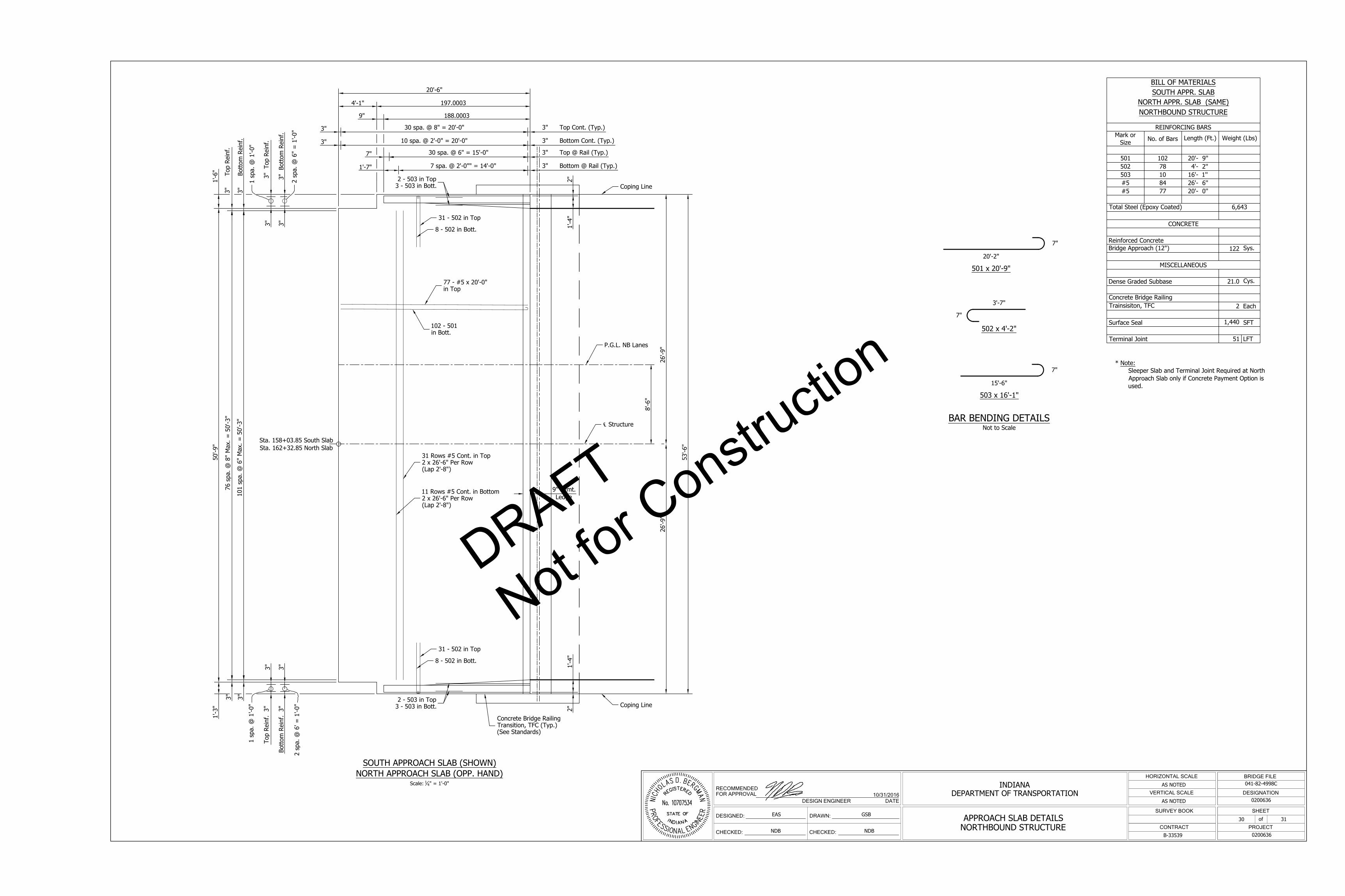
DESIGN ENGINEER DATE
RECOMMENDED
FOR APPROVAL
DESIGNED:
CHECKED:
DRAWN:
CHECKED:
HORIZONTAL SCALE
VERTICAL SCALE
SURVEY BOOK
CONTRACT PROJECT
of
SHEET
DESIGNATION
BRIDGE FILE
INDIANA
DEPARTMENT OF TRANSPORTATION
B-33539
041-82-4998C
0200636
0200636
AS NOTED
AS NOTED
EAS
NDB
GSB
NDB
31
10/31/2016
APPROACH SLAB DETAILS
NORTHBOUND STRUCTURE
30 spa. @ 8" = 20'-0"
10 spa. @ 2'-0" = 20'-0"
20'-6"
50'-9"
76 spa. @
8" M
ax. =
50'-3"
101 spa. @
6" M
ax. =
50'-3"
3" Bottom
Reinf.
3" Top Reinf.
3"
3"
9"
197.00034'-1"
188.0003
31 Rows #5 Cont. in Top
2 x 26'-6" Per Row
(Lap 2'-8")
11 Rows #5 Cont. in Bottom
2 x 26'-6" Per Row
(Lap 2'-8")
3"
3" Top Cont. (Typ.)
3" Bottom Cont. (Typ.)
3"
1'-3"
102 - 501
in Bott.
77 - #5 x 20'-0"
in Top
2"
1'-4"
2"
1'-4"
7"
30 spa. @ 6" = 15'-0" 3" Top @ Rail (Typ.)
1'-7"
7 spa. @ 2'-0"" = 14'-0" 3" Bottom @ Rail (Typ.)
9" Pvmt.
Ledge
31 - 502 in Top
8 - 502 in Bott.
31 - 502 in Top
8 - 502 in Bott.
Concrete Bridge Railing
Transition, TFC (Typ.)
(See Standards)
Top Reinf. 3"
3"
Bottom
Reinf. 3"
3"
3"
3"
3" Top Reinf.
3" Bottom
Reinf.
1'-6"
1 spa. @
1'-0"
2 spa. @
6" =
1'-0"
1 spa. @
1'-0"
2 spa. @
6' =
1'-0"
53'-6"
26'-9"
26'-9"
P.G.L. NB Lanes
℄ Structure
Sta. 158+03.85 South Slab
Sta. 162+32.85 North Slab
2 - 503 in Top
3 - 503 in Bott.
2 - 503 in Top
3 - 503 in Bott.
Coping Line
8'-6"
Coping Line
SOUTH APPROACH SLAB (SHOWN)
NORTH APPROACH SLAB (OPP. HAND)
Scale:
1
4
" = 1'-0"
20'-2"
3'-7"
15'-6"
7"
7"
7"
501 x 20'-9"
502 x 4'-2"
503 x 16'-1"
BAR BENDING DETAILS
Not to Scale
30
BILL OF MATERIALS
SOUTH APPR. SLAB
NORTH APPR. SLAB (SAME)
NORTHBOUND STRUCTURE
REINFORCING BARS
Mark or
Size
No. of Bars
Length (Ft.) Weight (Lbs)
501 102 20'- 9''
502 78 4'- 2''
503 10 16'- 1''
#5 84 26'- 6''
#5 77 20'- 0''
Total Steel (Epoxy Coated) 6,643
CONCRETE
Reinforced Concrete
Bridge Approach (12")
122
Sys.
MISCELLANEOUS
Dense Graded Subbase 21.0
Cys.
Concrete Bridge Railing
Trainsisiton, TFC
2 Each
Surface Seal
1,440
SFT
Terminal Joint 51 LFT
* Note:
Sleeper Slab and Terminal Joint Required at North
Approach Slab only if Concrete Payment Option is
used.
DRAFT
Not for C
onstructio
n

DESIGN ENGINEER DATE
RECOMMENDED
FOR APPROVAL
DESIGNED:
CHECKED:
DRAWN:
CHECKED:
HORIZONTAL SCALE
VERTICAL SCALE
SURVEY BOOK
CONTRACT PROJECT
of
SHEET
DESIGNATION
BRIDGE FILE
INDIANA
DEPARTMENT OF TRANSPORTATION
B-33539
041-82-4998C
0200636
0200636
AS NOTED
AS NOTED
EAS
NDB
GSB
NDB
31
10/31/2016
BRIDGE SUMMARY
31
SUMMARY OF BRIDGE QUANTITIES
ITEM
CONCRETE
CONCRETE
RAILING
CLASS C
REINF.
BARS
REINF.
BARS,
EPOXY
COATED
BARRIER
DELIN-
EATORS
REINF.
CONC.
BRIDGE
APPROACH
(12 IN)
DENSE
GRADED
SUBBASE
STRUCT.
STEEL
FIELD
DRILLED
HOLES
PILES
GRATES,
BASINS, &
FITTINGS,
CAST IRON
EXP. JOINT
TYPE ___
CONC. STR. MEMBERS
SURFACE
SEAL
CLASS C CLASS A CLASS B CLASS B
STEEL
PIPE
(SIZE)
STEEL PIPE
EPOXY
COATED
(SIZE)
STEEL H
(12 x 53)
STEEL H
EPOXY
COATED
STEEL H
REINF.
CONC.
ENCASED
TEST PILE,
DYNAMIC,
PRODUCTI
ON
TEST PILE,
DYNAMIC,
RESTRICKE
PILE SHOE
(12 x 53)
PILE TIP
STEEL H
(SIZE)
CORED HOLE
IN ROCK
BOX BEAM
TYPE &
SIZE
I-BEAM
TYPE &
SIZE
SUPERSTR SUBSTR
ABOVE
FTG.
IN
FTG.
CYS CYS CYS CYS CYS LBS LBS EACH SYS CYS LBS EACH LFT LFT LFT LFT LFT LFT EACH EACH EACH NO. LFT EACH LFT LFT LFT SFT
SUPERSTRUCTURE
Deck 533.9
278,655 59,029
14
22,000
Concrete Barrier Rail/Transitions
74.7
16,715
22
5,000
SUBSTRUCTURE
End Bent 1 28.8 7.6
5,644
176
Pier 2 1.4 184 36
Pier 3 1.4 184 36
Pier 4 1.4 184 36
Pier 5 24.7
3,687
End Bent 6 16.1 19.5
5,853
48
Wingwall 1
11.0
3,035
Wingwall 6
4.6
1,215
Approach Slabs 13,286
244.0 42.0
2,880
TOTALS 578.8 71.6 74.7
4,239 324,403
22 244.0 42.0
59,029
332 14
29,880
DRAFT
Not for C
onstructio
n