Embed Size (px)
Citation preview
©The Carlstar Group LLC. All rights reserved. IND-L-1501
U.S.A. Customer Service: 866-773-2926
CANADA Customer Service: 866-797-2358
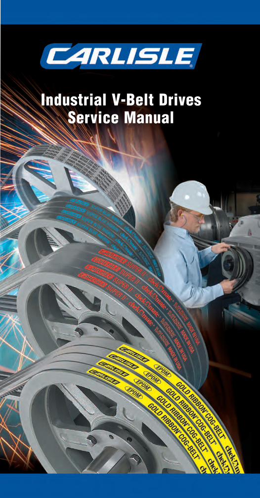
Industrial V-Belt DrivesService Manual
The Right Belt for the Job
1
2
3
4
5
6
7
8
9
10
11
12
13
14
3
5
67
8
9
10
1312
The Right Belt for the Job
CarlisleBelts.com CarlisleBelts.com
*
*
*
*
Safety Note �WARNING
Safety must be considered a basic factor in machinery operation at alltimes. Most accidents are the result of carelessness or negligence.Power transmission products such as those listed in this catalog arepotentially dangerous and must be guarded by the contractor, installer,purchaser, owner, and user as required by applicable laws, regu lations,standards, and good safety practice.
Failure to follow proper procedures for installation, care, maintenanceand storage of products may result in failure to perform properly andmay result in damage to property and serious bodily injury. Make surethat the product selected for any application is recommended for thatservice.
It is the responsibility of the contractor, installer, purchaser, owner, anduser to install, maintain, and operate the parts or componentsmanufactured and supplied by The Carlstar Group in such a manner asto comply with all occupational safety laws, federal, state and locallaws, ordinances, regulations, etc.
CAUTION
Guards, access doors, and covers must be securely fastenedbefore operating any equipment. If parts are to be inspected,cleaned, observed, or general maintenance performed, the motordriving the part or components is to be locked out electrically insuch a manner that it cannot be started by anyone. Failure to followthese instructions may result in property damage, personal injury,or death.
AIRCRAFT WARNING!
Carlisle belts and pulleys are not designed or intended for aircraft use.Do not use Carlisle belts on aircraft propeller, rotor or accessory drives.Do not use Carlisle belts on helicopters or private, commercial, orultralight aircraft.
1
2
4
14
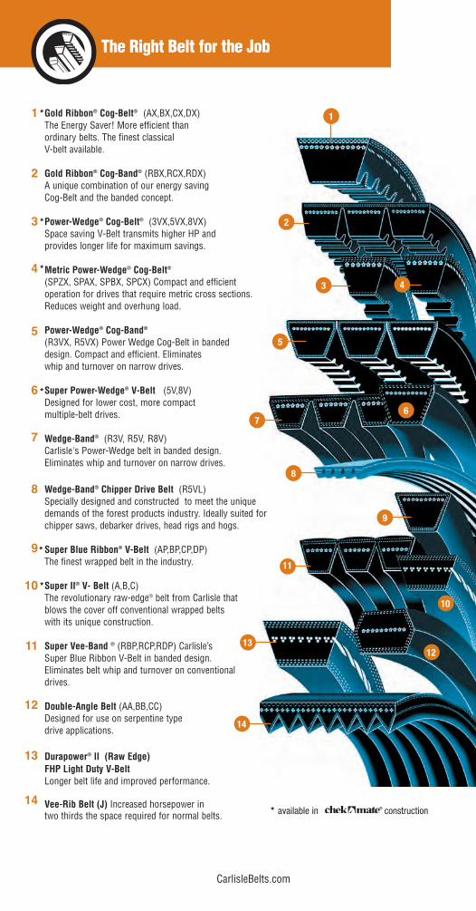
* available in construction
Gold Ribbon® Cog-Belt® (AX,BX,CX,DX)The Energy Saver! More efficient than ordinary belts. The finest classical V-belt available.
Gold Ribbon® Cog-Band® (RBX,RCX,RDX)A unique combination of our energy saving Cog-Belt and the banded concept.
Power-Wedge® Cog-Belt® (3VX,5VX,8VX) Space saving V-Belt transmits higher HP andprovides longer life for maximum savings.
Metric Power-Wedge® Cog-Belt®
(SPZX, SPAX, SPBX, SPCX) Compact and efficient operation for drives that require metric cross sections. Reduces weight and overhung load.
Power-Wedge® Cog-Band®
(R3VX, R5VX) Power Wedge Cog-Belt in banded design. Compact and efficient. Eliminateswhip and turnover on narrow drives.
Super Power-Wedge® V-Belt (5V,8V)Designed for lower cost, more compact multiple-belt drives.
Wedge-Band® (R3V, R5V, R8V)Carlisle's Power-Wedge belt in banded design. Eliminates whip and turnover on narrow drives.
Wedge-Band® Chipper Drive Belt (R5VL) Specially designed and constructed to meet the unique demands of the forest products industry. Ideally suited for chipper saws, debarker drives, head rigs and hogs.
Super Blue Ribbon® V-Belt (AP,BP,CP,DP) The finest wrapped belt in the industry.
Super II® V- Belt (A,B,C)The revolutionary raw-edge® belt from Carlisle that blows the cover off conventional wrapped belts with its unique construction.
Super Vee-Band ® (RBP,RCP,RDP) Carlisle’s Super Blue Ribbon V-Belt in banded design. Eliminates belt whip and turnover on conventional drives.
Double-Angle Belt (AA,BB,CC)Designed for use on serpentine type drive applications.
Durapower® ll (Raw Edge) FHP Light Duty V-BeltLonger belt life and improved performance.
Vee-Rib Belt (J) Increased horsepower in two thirds the space required for normal belts.
11
®
*
*
1
Table of Contents
The Carlisle V-belt Drive Service Manual has been prepared with the double purpose of: helping you AVOID V-belt drive problems by presenting astep-by-step replacement procedure and helping you SOLVE V-belt drive problems by offering troubleshooting techniques.
Subject Page
V-Belt Construction . . . . . . . . . . . . . . . . . . . . . . . . . . . . . . . . . . . . . . . . . .2
V-Belt Drive Advantages . . . . . . . . . . . . . . . . . . . . . . . . . . . . . . . . . . . . . .3
Section 1– Preventive Maintenance andInstallation of V-Belt Drives . . . . . . . . . . . . . . . . . . . . . . . . . . . . . . .4-9
V-Belt Installation Check List . . . . . . . . . . . . . . . . . . . . . . . . . . . . . . . . . .9
Section 2 – Corrective Maintenance andTroubleshooting of V-Belt Drives . . . . . . . . . . . . . . . . . . . . . . . . .10-35
V-Belt Drive Troubleshooting Guide . . . . . . . . . . . . . . . . . . . . . . . . . .12-13
Troubleshooting Installation Problems . . . . . . . . . . . . . . . . . . . . . . . .14-21
Troubleshooting Selection Problems . . . . . . . . . . . . . . . . . . . . . . . . .22-27
Troubleshooting Environmental Problems . . . . . . . . . . . . . . . . . . . . .28-31
Troubleshooting Design Problems . . . . . . . . . . . . . . . . . . . . . . . . . . .32-35
Installation and Take-Up Data . . . . . . . . . . . . . . . . . . . . . . . . . . . . . . . . .36
V-Belt Tensioning . . . . . . . . . . . . . . . . . . . . . . . . . . . . . . . . . . . . . . .37-38
V-Belt Deflection Force Values . . . . . . . . . . . . . . . . . . . . . . . . . . . . . . . .39
Topical Index . . . . . . . . . . . . . . . . . . . . . . . . . . . . . . . . . . . . . . . . . . . . .40
� WARNING - SAFETY NOTE
Failure to follow recommended application information and recommended proceduresfor installation, care, maintenance and storage of products may result in failure to perform properly and may result in damage to property and serious bodily injury. Makesure that product selected for any application is recommended for that service. ContactCarlisle or your Carlisle distributor for assistance or specific recommendations.
Guidelines presented in this manual are suggestions to help install and maintain beltsproperly. Always follow the recommendations of the original equipment manufacturer.
2
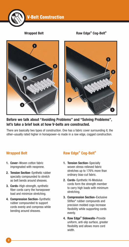
Wrapped Belt
1. Cover–Woven cotton fabric impregnated with neoprene.
2. Tension Section–Synthetic rubber specially compounded to stretch as belt bends around sheaves.
3. Cords–High-strength, synthetic fiber cords carry the horsepower load and minimize stretching.
4. Compression Section–Synthetic rubber compounded to support cords evenly and compress while bending around sheaves.
Raw Edge® Cog-Belt®
1. Tension Section–Specially woven stress-relieved fabric stretches up to 176% more than ordinary bias-cut fabric.
2. Cords–Synthetic Hi-Modulus cords form the strength member to carry high loads with minimum stretching.
3. Compression Section–Exclusive Stiflex® rubber compounds and precision molded cogs increase flexibility while supporting cords evenly.
4. Raw Edge® Sidewalls–Provide uniform, anti-slip surface, greater flexibility and allows more cord width.
Wrapped Belt Raw Edge® Cog-Belt®
Before we talk about “Avoiding Problems” and “Solving Problems”,let’s take a brief look at how V-belts are constructed.There are basically two types of construction. One has a fabric cover surrounding it; theother–usually rated higher in horsepower–is made in a raw edge, cogged construction.
V-Belt Construction
1
4
4
3
1
2
3
2
3
V-Belt Drive Advantages
V-belt drives provide many maintenance advantages that help in your daily struggle to reduce equipment repairs and to hold downtime to a minimum.
1. They are rugged–they will give years of trouble-free performance when given minimal attention...even under adverse conditions.
2. They are clean–require no lubrication.
3. They are efficient–performing with an average of 93-95% efficiency. Raw-edge cog belts are 95-97% efficient.
4. They are smooth starting and running.
5. They cover extremely wide horsepower ranges.
6. They permit a wide range of driven speeds, using standard electric motors.
7. They dampen vibration between driving and driven machines.
8. They are quiet.
9. They act as a “safety fuse” in the powertrain.
10. V-belts and sheaves wear gradually–making preventive and corrective maintenance simple and easy.
You will notice Reference Key Numbers (such as -1) appear throughout this section. These refer to a more detailed discussion with illustrations relating to thesubject in Section 2 (Corrective Maintenance and Troubleshooting).
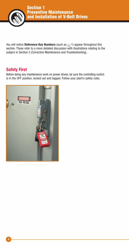
Safety FirstBefore doing any maintenance work on power drives, be sure the controlling switch is in the OFF position, locked out and tagged. Follow your plant’s safety rules.
4
A
Section 1Preventive Maintenance and Installation of V-Belt Drives
5
Preventive Maintenance and Installation of V-Belt Drives
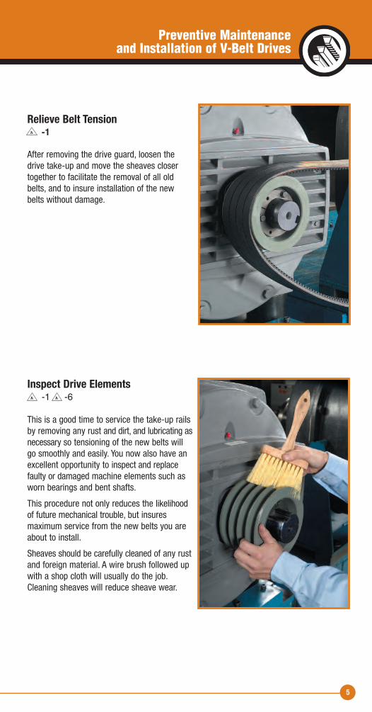
Relieve Belt Tension -1
After removing the drive guard, loosen thedrive take-up and move the sheaves closertogether to facilitate the removal of all oldbelts, and to insure installation of the new belts without damage.
Inspect Drive Elements-1 -6
This is a good time to service the take-up railsby removing any rust and dirt, and lubricating asnecessary so tensioning of the new belts willgo smoothly and easily. You now also have anexcellent opportunity to inspect and replacefaulty or damaged machine elements such asworn bearings and bent shafts.
This procedure not only reduces the likelihoodof future mechanical trouble, but insures maximum service from the new belts you areabout to install.
Sheaves should be carefully cleaned of any rustand foreign material. A wire brush followed upwith a shop cloth will usually do the job.Cleaning sheaves will reduce sheave wear.
A
AA
6
Section 1Preventive Maintenance and Installation of V-Belt Drives
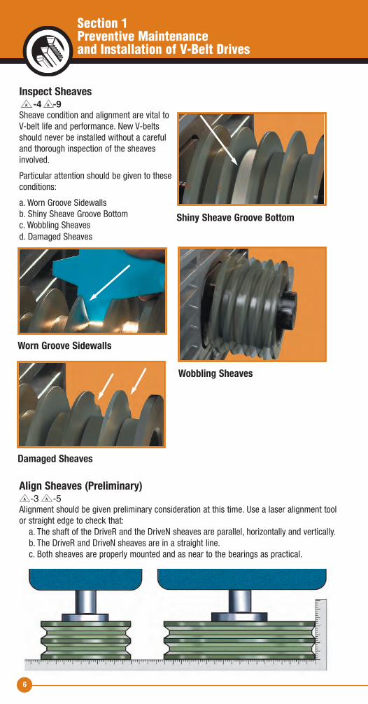
Inspect Sheaves -4 -9
Sheave condition and alignment are vital toV-belt life and performance. New V-beltsshould never be installed without a carefuland thorough inspection of the sheavesinvolved.
Particular attention should be given to theseconditions:
a. Worn Groove Sidewallsb. Shiny Sheave Groove Bottomc. Wobbling Sheavesd. Damaged Sheaves
Align Sheaves (Preliminary)-3 -5
Alignment should be given preliminary consideration at this time. Use a laser alignment toolor straight edge to check that: a. The shaft of the DriveR and the DriveN sheaves are parallel, horizontally and vertically. b. The DriveR and DriveN sheaves are in a straight line. c. Both sheaves are properly mounted and as near to the bearings as practical.
A A
Shiny Sheave Groove Bottom
Wobbling Sheaves
Worn Groove Sidewalls
Damaged Sheaves
A A
7
Preventive Maintenance and Installation of V-Belt Drives
Select Replacement Belts-1 -2 -3 -4
After you have made any necessary corrections in your V-belt drive elements, the nextstep is the selection of the right replacement belts.
In replacing sets of V-belts, here are some Very Important Reminders:
• NEVER MIX NEW AND USED BELTS ON A DRIVE • NEVER MIX BELTS FROM MORE THAN ONE MANUFACTURER • ALWAYS REPLACE WITH THE RIGHT TYPE OF V-BELT • ALWAYS OBSERVE V-BELT MATCHING LIMITS
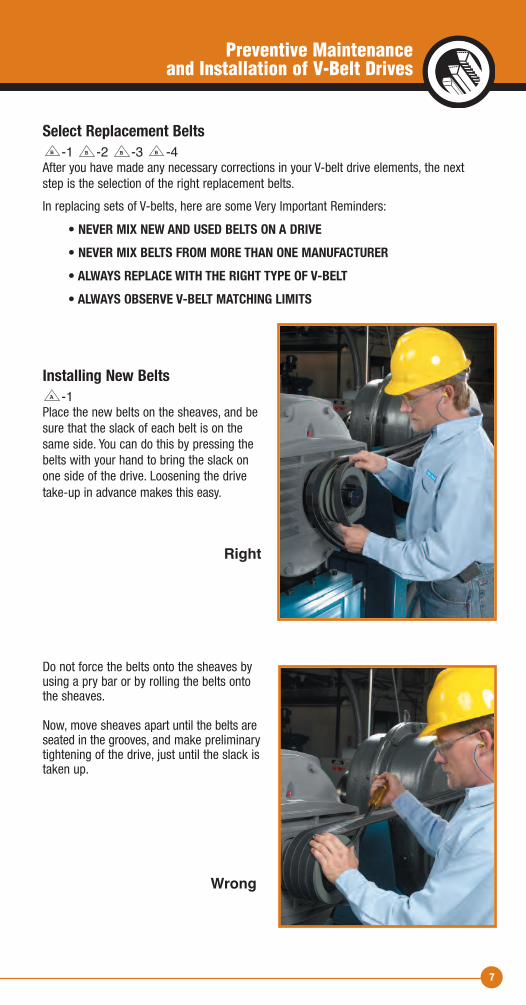
Installing New Belts-1
Place the new belts on the sheaves, and besure that the slack of each belt is on thesame side. You can do this by pressing thebelts with your hand to bring the slack on one side of the drive. Loosening the drivetake-up in advance makes this easy.
Do not force the belts onto the sheaves byusing a pry bar or by rolling the belts onto the sheaves.
Now, move sheaves apart until the belts areseated in the grooves, and make preliminarytightening of the drive, just until the slack istaken up.
A
BBBB
Right
Wrong
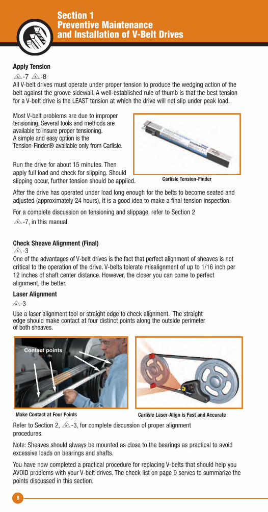
Apply Tension-7 -8
All V-belt drives must operate under proper tension to produce the wedging action of thebelt against the groove sidewall. A well-established rule of thumb is that the best tensionfor a V-belt drive is the LEAST tension at which the drive will not slip under peak load.
Most V-belt problems are due to improper tensioning. Several tools and methods are available to insure proper tensioning. A simple and easy option is the Tension-Finder® available only from Carlisle.
Run the drive for about 15 minutes. Thenapply full load and check for slipping. Shouldslipping occur, further tension should be applied.
After the drive has operated under load long enough for the belts to become seated andadjusted (approximately 24 hours), it is a good idea to make a final tension inspection.
For a complete discussion on tensioning and slippage, refer to Section 2
-7, in this manual.
Check Sheave Alignment (Final) -3
One of the advantages of V-belt drives is the fact that perfect alignment of sheaves is notcritical to the operation of the drive. V-belts tolerate misalignment of up to 1/16 inch per12 inches of shaft center distance. However, the closer you can come to perfect alignment, the better.
Laser Alignment-3
Use a laser alignment tool or straight edge to check alignment. The straightedge should make contact at four distinct points along the outside perimeterof both sheaves.
Refer to Section 2, -3, for complete discussion of proper alignment procedures.
Note: Sheaves should always be mounted as close to the bearings as practical to avoidexcessive loads on bearings and shafts.
You have now completed a practical procedure for replacing V-belts that should help youAVOID problems with your V-belt drives. The check list on page 9 serves to summarize thepoints discussed in this section.
A
A
A
A
A
8
Contact points
Carlisle Laser-Align is Fast and AccurateMake Contact at Four Points
A
Section 1Preventive Maintenance and Installation of V-Belt Drives
Carlisle Tension-Finder
9
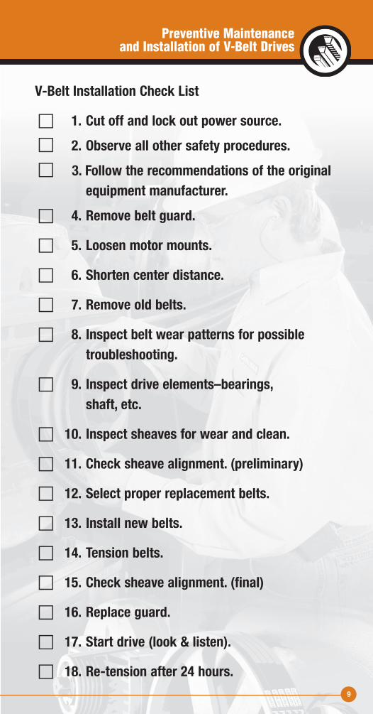
V-Belt Installation Check List
c 1. Cut off and lock out power source.c 2. Observe all other safety procedures.c 3. Follow the recommendations of the original equipment manufacturer.c 4. Remove belt guard.
c 5. Loosen motor mounts.
c 6. Shorten center distance.
c 7. Remove old belts.
c 8. Inspect belt wear patterns for possible troubleshooting.
c 9. Inspect drive elements–bearings, shaft, etc.
c 10. Inspect sheaves for wear and clean.
c 11. Check sheave alignment. (preliminary)
c 12. Select proper replacement belts.
c 13. Install new belts.
c 14. Tension belts.
c 15. Check sheave alignment. (final)
c 16. Replace guard.
c 17. Start drive (look & listen).
c 18. Re-tension after 24 hours.
Preventive Maintenance and Installation of V-Belt Drives
10
Section 2Corrective Maintenance and Troubleshooting of V-Belt Drives
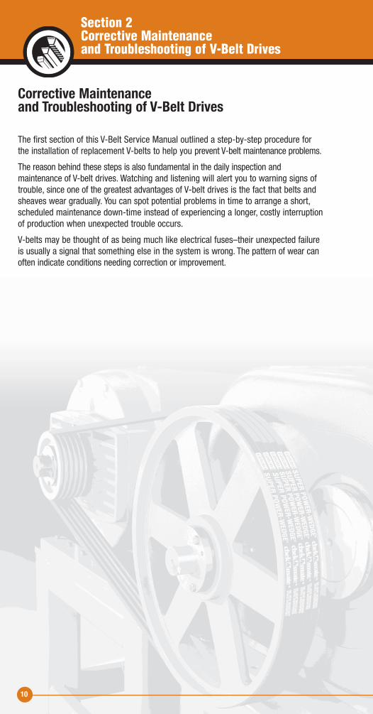
Corrective Maintenance and Troubleshooting of V-Belt Drives
The first section of this V-Belt Service Manual outlined a step-by-step procedure for the installation of replacement V-belts to help you prevent V-belt maintenance problems.
The reason behind these steps is also fundamental in the daily inspection and maintenance of V-belt drives. Watching and listening will alert you to warning signs oftrouble, since one of the greatest advantages of V-belt drives is the fact that belts andsheaves wear gradually. You can spot potential problems in time to arrange a short,scheduled maintenance down-time instead of experiencing a longer, costly interruptionof production when unexpected trouble occurs.
V-belts may be thought of as being much like electrical fuses –their unexpected failureis usually a signal that something else in the system is wrong. The pattern of wear canoften indicate conditions needing correction or improvement.
11
Corrective Maintenance and Troubleshooting of V-Belt Drives
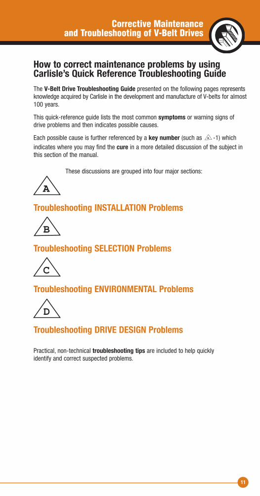
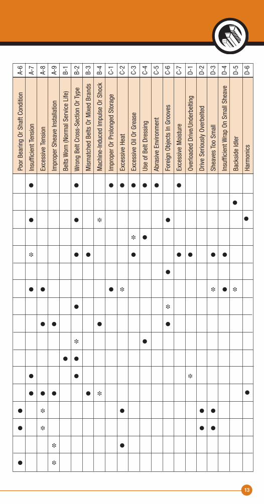
How to correct maintenance problems by usingCarlisle’s Quick Reference Troubleshooting GuideThe V-Belt Drive Troubleshooting Guide presented on the following pages representsknowledge acquired by Carlisle in the development and manufacture of V-belts for almost100 years.
This quick-reference guide lists the most common symptoms or warning signs ofdrive problems and then indicates possible causes.
Each possible cause is further referenced by a key number (such as -1) which indicates where you may find the cure in a more detailed discussion of the subject inthis section of the manual.
These discussions are grouped into four major sections:
Troubleshooting INSTALLATION Problems
Troubleshooting SELECTION Problems
Troubleshooting ENVIRONMENTAL Problems
Troubleshooting DRIVE DESIGN Problems
Practical, non-technical troubleshooting tips are included to help quicklyidentify and correct suspected problems.
A
A
B
C
D
A-1
A-2
A-3
A-4
A-5
12
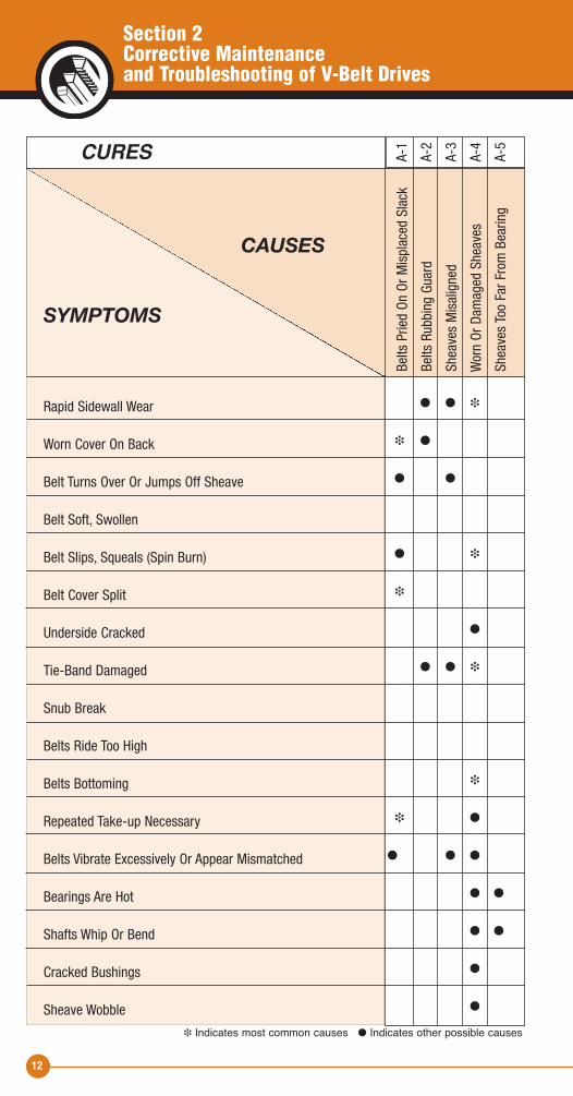
CURES
CAUSES
SYMPTOMS
Rapid Sidewall Wear
Worn Cover On Back
Belt Turns Over Or Jumps Off Sheave
Belt Soft, Swollen
Belt Slips, Squeals (Spin Burn)
Belt Cover Split
Underside Cracked
Tie-Band Damaged
Snub Break
Belts Ride Too High
Belts Bottoming
Repeated Take-up Necessary
Belts Vibrate Excessively Or Appear Mismatched
Bearings Are Hot
Shafts Whip Or Bend
Cracked Bushings
Sheave Wobble
� Indicates most common causes � Indicates other possible causes
� � �
� �
� �
� �
�
�
� � �
�
� �
� � �
� �
� �
�
�
Belts Pried On Or M
isplaced Slack
Belts Rubbing Guard
Sheaves Misaligned
Worn Or Dam
aged Sheaves
Sheaves Too Far From Bearing
Section 2Corrective Maintenance and Troubleshooting of V-Belt Drives
13
� � � � � � � �
�
� � � �
� �
� � � � � � � �
�
� � � � � � �
� �
� � � �
� �
� �
� � �
� � � � �
� � � � �
� � � �
� �
� �
Poor Bearing Or Shaft Condition
Insufficient Tension
Excessive Tension
Improper Sheave Installation
Belts Worn (Normal Service Life)
Wrong Belt Cross-Section Or Type
Mismatched Belts Or M
ixed Brands
Machine-Induced Impulse Or Shock
Improper Or Prolonged Storage
Excessive Heat
Excessive Oil Or G
rease
Use of Belt D
ressing
Abrasive Environm
ent
Foreign Objects In Grooves
Excessive Moisture
Overloaded Drive/Underbelting
Drive Seriously Overbelted
Sheaves Too Sm
all
Insufficient W
rap On Small Sheave
Backside Idler
Harmonics
A-6
A-7
A-8
A-9
B-1
B-2
B-3
B-4
C-1
C-2
C-3
C-4
C-5
C-6
C-7
D-1
D-2
D-3
D-4
D-5
D-6
�
�

14
Troubleshooting Installation ProblemsAs pointed out in Section 1 of this manual, preventive maintenance by using properinstallation techniques is important for long, trouble-free V-belt service.
Occasionally, however, you will find it necessary to correct problems caused by improperinstallation. This section deals with these problems and troubleshooting procedures.
Section 2Troubleshooting Installation Problems
15
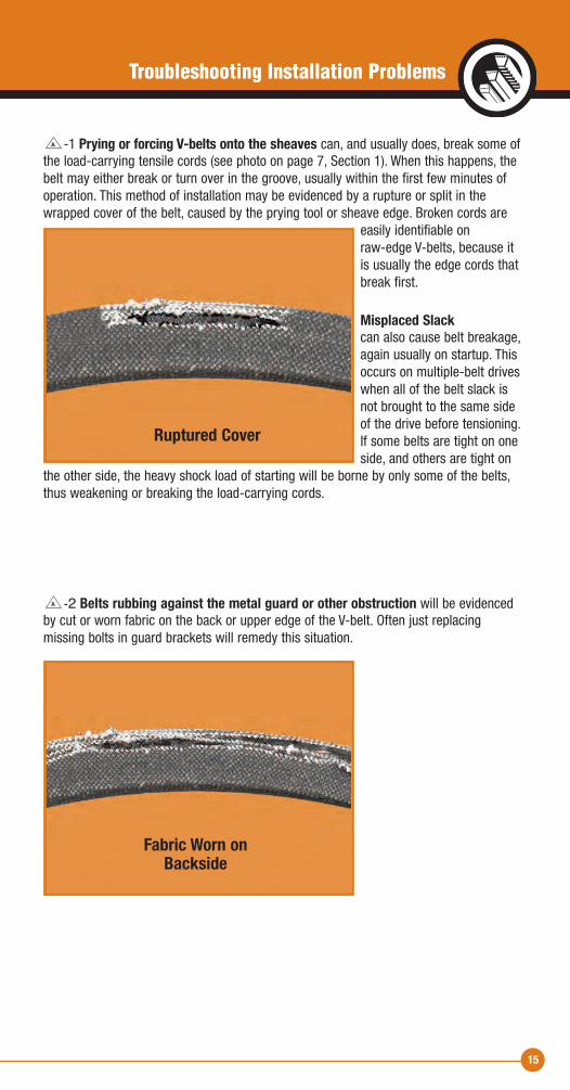
-2 Belts rubbing against the metal guard or other obstruction will be evidencedby cut or worn fabric on the back or upper edge of the V-belt. Often just replacing missing bolts in guard brackets will remedy this situation.
A
-1 Prying or forcing V-belts onto the sheaves can, and usually does, break some ofthe load-carrying tensile cords (see photo on page 7, Section 1). When this happens, thebelt may either break or turn over in the groove, usually within the first few minutes ofoperation. This method of installation may be evidenced by a rupture or split in thewrapped cover of the belt, caused by the prying tool or sheave edge. Broken cords are
easily identifiable on raw-edge V-belts, because itis usually the edge cords thatbreak first.
Misplaced Slackcan also cause belt breakage,again usually on startup. Thisoccurs on multiple-belt driveswhen all of the belt slack isnot brought to the same sideof the drive before tensioning.If some belts are tight on oneside, and others are tight on
the other side, the heavy shock load of starting will be borne by only some of the belts,thus weakening or breaking the load-carrying cords.
A
Troubleshooting Installation Problems
Ruptured Cover
Fabric Worn onBackside
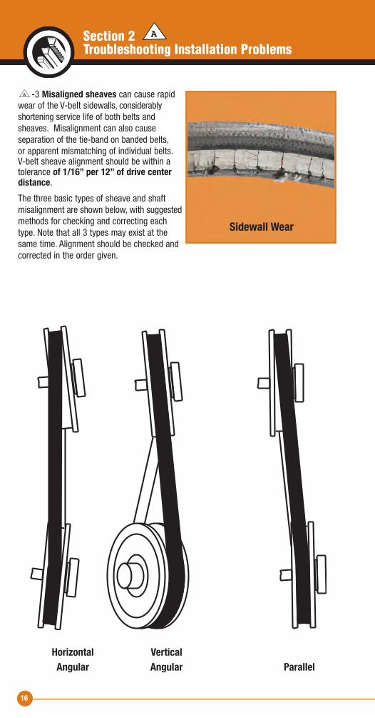
-3 Misaligned sheaves can cause rapidwear of the V-belt sidewalls, considerably shortening service life of both belts andsheaves. Misalignment can also cause separation of the tie-band on banded belts, or apparent mismatching of individual belts. V-belt sheave alignment should be within atolerance of 1/16” per 12” of drive center distance.The three basic types of sheave and shaft misalignment are shown below, with suggestedmethods for checking and correcting eachtype. Note that all 3 types may exist at thesame time. Alignment should be checked andcorrected in the order given.
A
16
A
Sidewall Wear
Horizontal Vertical Angular Angular Parallel
Section 2Troubleshooting Installation Problems
17
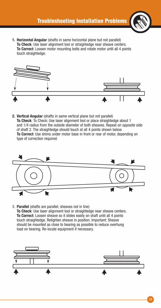
1. Horizontal Angular (shafts in same horizontal plane but not parallel) To Check: Use laser alignment tool or straightedge near sheave centers. To Correct: Loosen motor mounting bolts and rotate motor until all 4 points touch straightedge.
2. Vertical Angular (shafts in same vertical plane but not parallel) To Check: To Check: Use laser alignment tool or place straightedge about 1 and 1/4 radius from the outside diameter of both sheaves. Repeat on opposite sideof shaft 2. The straightedge should touch at all 4 points shown below.
To Correct: Use shims under motor base in front or rear of motor, depending ontype of correction required.
3. Parallel (shafts are parallel; sheaves not in line) To Check: Use laser alignment tool or straightedge near sheave centers. To Correct: Loosen sheave so it slides easily on shaft until all 4 points touch straightedge. Retighten sheave in position. Important: Sheave should be mounted as close to bearing as possible to reduce overhung load on bearing. Re-locate equipment if necessary.
Troubleshooting Installation Problems
18
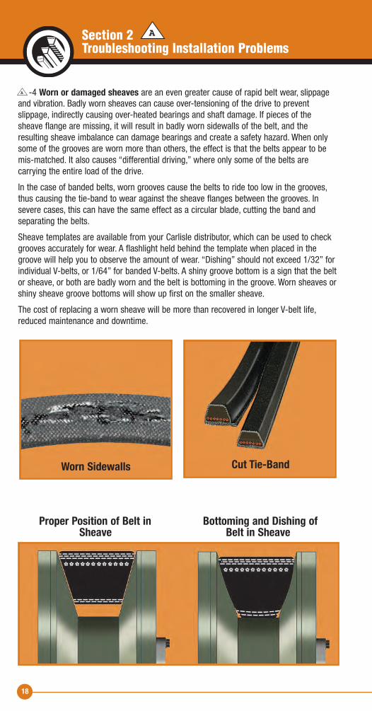
-4 Worn or damaged sheaves are an even greater cause of rapid belt wear, slippageand vibration. Badly worn sheaves can cause over-tensioning of the drive to prevent slippage, indirectly causing over-heated bearings and shaft damage. If pieces of thesheave flange are missing, it will result in badly worn sidewalls of the belt, and the resulting sheave imbalance can damage bearings and create a safety hazard. When onlysome of the grooves are worn more than others, the effect is that the belts appear to bemis-matched. It also causes “differential driving,” where only some of the belts are carrying the entire load of the drive.
In the case of banded belts, worn grooves cause the belts to ride too low in the grooves,thus causing the tie-band to wear against the sheave flanges between the grooves. Insevere cases, this can have the same effect as a circular blade, cutting the band and separating the belts.
Sheave templates are available from your Carlisle distributor, which can be used to checkgrooves accurately for wear. A flashlight held behind the template when placed in thegroove will help you to observe the amount of wear. “Dishing” should not exceed 1/32” forindividual V-belts, or 1/64” for banded V-belts. A shiny groove bottom is a sign that the beltor sheave, or both are badly worn and the belt is bottoming in the groove. Worn sheaves orshiny sheave groove bottoms will show up first on the smaller sheave.
The cost of replacing a worn sheave will be more than recovered in longer V-belt life,reduced maintenance and downtime.
A
Worn Sidewalls
Proper Position of Belt in Bottoming and Dishing of Sheave Belt in Sheave
Cut Tie-Band
ASection 2Troubleshooting Installation Problems
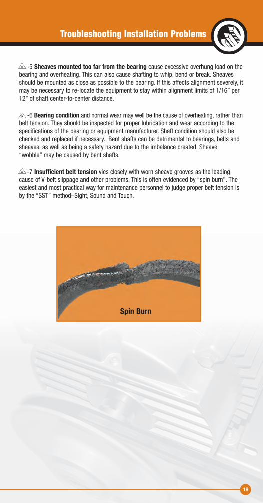
-5 Sheaves mounted too far from the bearing cause excessive overhung load on thebearing and overheating. This can also cause shafting to whip, bend or break. Sheavesshould be mounted as close as possible to the bearing. If this affects alignment severely, itmay be necessary to re-locate the equipment to stay within alignment limits of 1/16” per12” of shaft center-to-center distance.
-6 Bearing condition and normal wear may well be the cause of overheating, rather thanbelt tension. They should be inspected for proper lubrication and wear according to thespecifications of the bearing or equipment manufacturer. Shaft condition should also bechecked and replaced if necessary. Bent shafts can be detrimental to bearings, belts andsheaves, as well as being a safety hazard due to the imbalance created. Sheave “wobble” may be caused by bent shafts.
-7 Insufficient belt tension vies closely with worn sheave grooves as the leadingcause of V-belt slippage and other problems. This is often evidenced by “spin burn”. Theeasiest and most practical way for maintenance personnel to judge proper belt tension isby the “SST” method –Sight, Sound and Touch.
A
A
A
Spin Burn
Troubleshooting Installation Problems
19
20
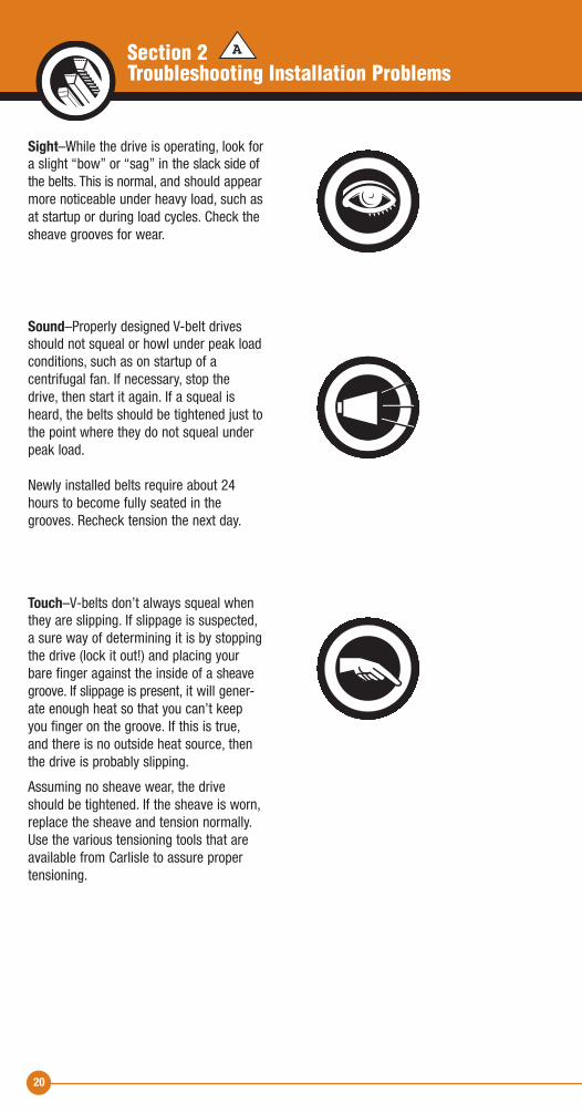
Sight–While the drive is operating, look fora slight “bow” or “sag” in the slack side ofthe belts. This is normal, and should appearmore noticeable under heavy load, such asat startup or during load cycles. Check thesheave grooves for wear.
Sound–Properly designed V-belt drivesshould not squeal or howl under peak loadconditions, such as on startup of a centrifugal fan. If necessary, stop thedrive, then start it again. If a squeal isheard, the belts should be tightened just tothe point where they do not squeal underpeak load.
Newly installed belts require about 24hours to become fully seated in thegrooves. Recheck tension the next day.
Touch–V-belts don’t always squeal whenthey are slipping. If slippage is suspected,a sure way of determining it is by stoppingthe drive (lock it out!) and placing yourbare finger against the inside of a sheavegroove. If slippage is present, it will gener-ate enough heat so that you can’t keepyou finger on the groove. If this is true,and there is no outside heat source, thenthe drive is probably slipping.
Assuming no sheave wear, the driveshould be tightened. If the sheave is worn,replace the sheave and tension normally.Use the various tensioning tools that areavailable from Carlisle to assure propertensioning.
ASection 2Troubleshooting Installation Problems
21
-8 Excessive tension on V-belts can be even more detrimental than too little tension,affecting not only the belts, but also bearings and shafts. Again, the best rule is to applyonly enough tension on the belts to keep them from slipping during startup or peak load-ing. Some indicators of excessive tensioning (but not always) are:
• Repeated belt breakage • Overheated bearings • Excessive vibration • Whipping or bent shafts • Belt underside is cracked
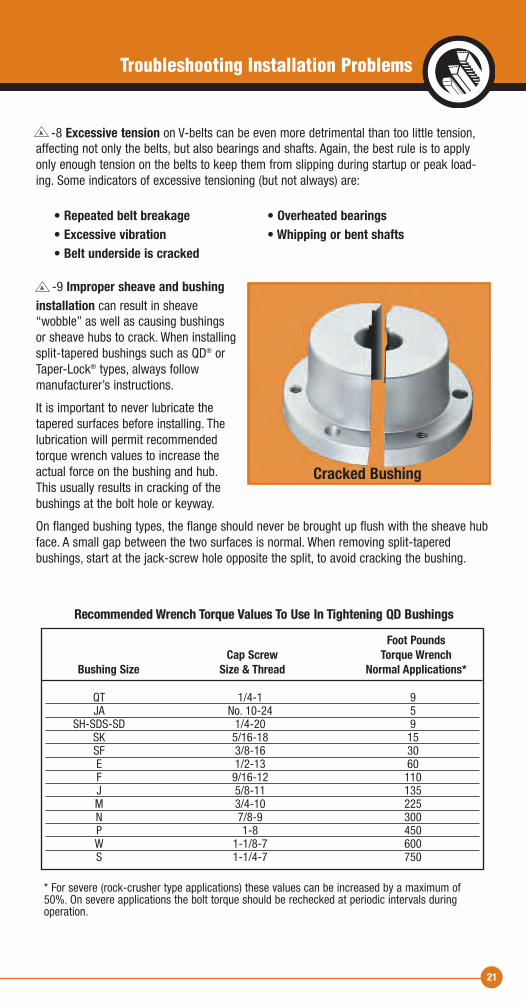
-9 Improper sheave and bushinginstallation can result in sheave “wobble” as well as causing bushings or sheave hubs to crack. When installingsplit-tapered bushings such as QD® orTaper-Lock® types, always follow manufacturer’s instructions.
It is important to never lubricate thetapered surfaces before installing. Thelubrication will permit recommendedtorque wrench values to increase theactual force on the bushing and hub. This usually results in cracking of thebushings at the bolt hole or keyway.
On flanged bushing types, the flange should never be brought up flush with the sheave hubface. A small gap between the two surfaces is normal. When removing split-tapered bushings, start at the jack-screw hole opposite the split, to avoid cracking the bushing.
A
A
Cracked Bushing
Foot Pounds Cap Screw Torque Wrench Bushing Size Size & Thread Normal Applications*
QT 1/4-1 9 JA No. 10-24 5 SH-SDS-SD 1/4-20 9 SK 5/16-18 15 SF 3/8-16 30 E 1/2-13 60 F 9/16-12 110 J 5/8-11 135 M 3/4-10 225 N 7/8-9 300 P 1-8 450 W 1-1/8-7 600 S 1-1/4-7 750
Recommended Wrench Torque Values To Use In Tightening QD Bushings
* For severe (rock-crusher type applications) these values can be increased by a maximum of50%. On severe applications the bolt torque should be rechecked at periodic intervals duringoperation.
Troubleshooting Installation Problems
22
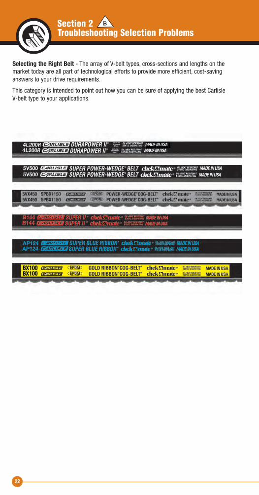
Selecting the Right Belt - The array of V-belt types, cross-sections and lengths on themarket today are all part of technological efforts to provide more efficient, cost-savinganswers to your drive requirements.
This category is intended to point out how you can be sure of applying the best Carlisle V-belt type to your applications.
BSection 2Troubleshooting Selection Problems
23
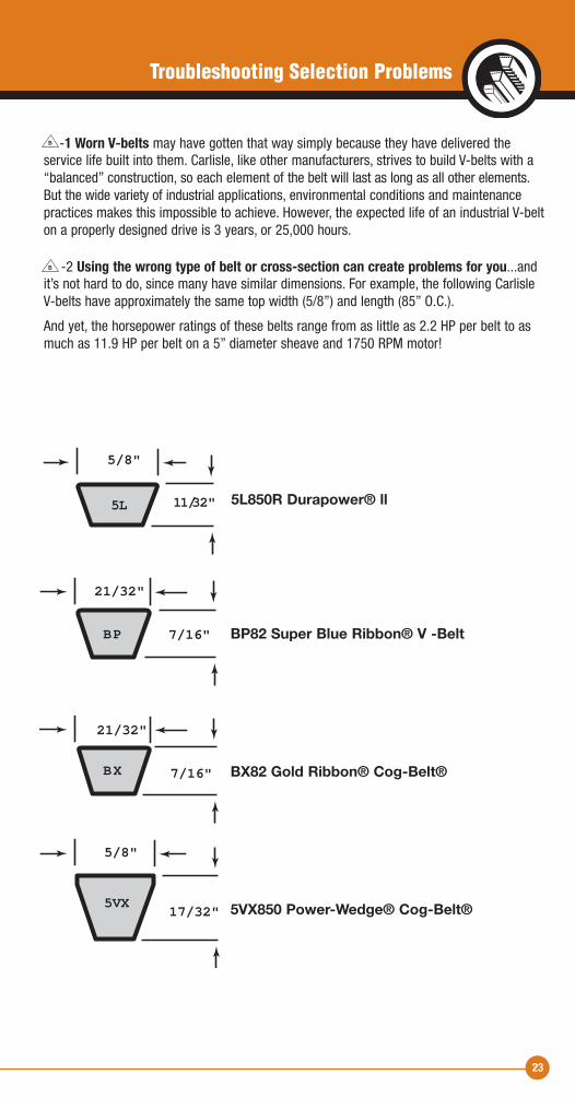
-1 Worn V-belts may have gotten that way simply because they have delivered the service life built into them. Carlisle, like other manufacturers, strives to build V-belts with a“balanced” construction, so each element of the belt will last as long as all other elements.But the wide variety of industrial applications, environmental conditions and maintenancepractices makes this impossible to achieve. However, the expected life of an industrial V-belton a properly designed drive is 3 years, or 25,000 hours.
-2 Using the wrong type of belt or cross-section can create problems for you...andit’s not hard to do, since many have similar dimensions. For example, the following Carlisle V-belts have approximately the same top width (5/8”) and length (85” O.C.).
And yet, the horsepower ratings of these belts range from as little as 2.2 HP per belt to asmuch as 11.9 HP per belt on a 5” diameter sheave and 1750 RPM motor!
B
B
5/8"
21/32"
21/32"
5/8"
11/32"
7/16"
7/16"
17/32"
5L850R Durapower! ll Light Duty FHP V-Belt5L
BP BP82 Super Blue Ribbon! V-Belt
BX82 Gold Ribbon! Cog-Belt!
5VX850 Power-Wedge! Cog-Belt!
BX
5VX
Troubleshooting Selection Problems
5L850R Durapower® ll
BP82 Super Blue Ribbon® V -Belt
BX82 Gold Ribbon® Cog-Belt®
5VX850 Power-Wedge® Cog-Belt®
24
A V-belt survey of your drives by a Carlisle Certified Drive Specialist can assure you ofusing the correct V-belt. This service may be obtained by contacting your CarlisleAuthorized Stocking Distributor. He maintains a full and convenient inventory of replacement belts and sheaves, and stands ready to assist you in selecting the proper size and type for each application.
Carlisle's Industrial Power Transmission catalog lists all types and sizes ofstock industrial belts and sheaves. The following suggestions will help in
selecting the proper belt.
DO match the correct belt cross-section to the sheave groove. (A-A, B-B,5V-5V, etc.)
DON’T use “B” section belts in “5V” grooves, or vice-versa. Check the sheave numberstamped on the rim if in doubt.
DON’T replace “A” or “B” heavy duty V-belts with “4L” or “5L” light duty (FHP) V-belts. FHPbelts are built for Fractional Horsepower applications, and usually run singly. Most multipledrives require heavy duty belts.
DO use V-belts marked “Oil and Heat Resistant” where oil or heat is present. The CarlisleGold Ribbon® Cog-Belt® and Power-Wedge® Cog-Belt® offer maximum heat and oil resistance –see key numbers -2 and -3
DO insist on a belt labeled “Static-dissipating” on drives operating in hazardous atmospheres.
DO use banded V-belts where vibration or shock loads can cause belts to turn over orjump out of the sheave grooves.
DO use matched sets from the same manufacturer (see key number -3)
DON’T mix old and new belts on a drive. They cannot be matched.
-3 Mismatched belts or mixed brands from different manufacturers cannot be matchedtogether, and will not deliver the service life they should.
Although all manufacturers use similar belt numbering systems, different brands with thesame number will differ slightly in dimensions and are not capable of being mixed in aset. Also, construction differences cause them to ride differently in the grooves, and tostretch differently.
It should be noted that the majority of complaints regarding belt matching are found to bedue to other causes, such as misalignment, improper tension and sheave wear. These factors should always be checked if belts seem to be mismatched.
Carlisle belts branded with the Chek-Mate® logo do not require the use of matchingcodes. Chek-Mate is a process that manufactures belts to meet or exceed Association forRubber Products Manufacturers (ARPM) tolerances for a matched set. Matching numbersare not required on Carlisle's Super Blue Ribbon, Super II, Super Power-Wedge, Power-Wedge and Gold Ribbon Cog-Belts which all carry the distinctive Chek-Mate logo.
B
C C
B
BSection 2Troubleshooting Selection Problems
25
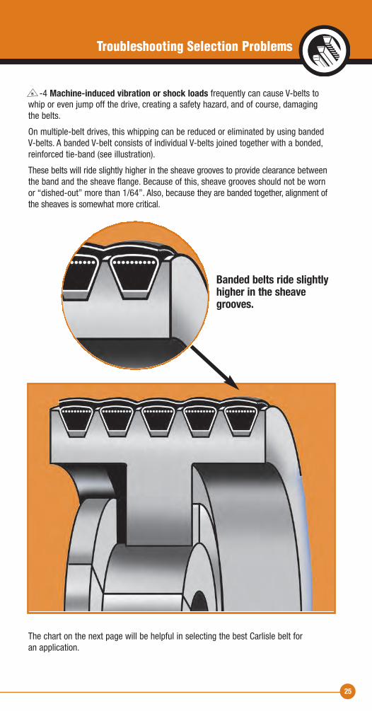
-4 Machine-induced vibration or shock loads frequently can cause V-belts towhip or even jump off the drive, creating a safety hazard, and of course, damaging the belts.
On multiple-belt drives, this whipping can be reduced or eliminated by using banded V-belts. A banded V-belt consists of individual V-belts joined together with a bonded,reinforced tie-band (see illustration).
These belts will ride slightly higher in the sheave grooves to provide clearance betweenthe band and the sheave flange. Because of this, sheave grooves should not be wornor “dished-out” more than 1/64”. Also, because they are banded together, alignment ofthe sheaves is somewhat more critical.
B
Banded belts ride slightlyhigher in the sheavegrooves.
The chart on the next page will be helpful in selecting the best Carlisle belt for an application.
Troubleshooting Selection Problems

Maximum Generic Belt Type Normal Belt Speed Carlisle Brand (Cross-Sections) HP Range (FT/Min)(1)
Super Blue Classical Multiple 1-500 6500 Ribbon (A, B, C, D)
Super ll Classical Multiple 1-500 6500 (A, B, C,)
Gold Ribbon Classical Cogged Multiple 1-500 6500 Cog-Belt* (AX, BX, CX, DX)
Super Narrow Multiple 1-1000 6500 Power-Wedge (3V, 5V, 8V)
Power-Wedge Narrow Cogged Multiple 1-600 6500 Cog-Belt* (3VX, 5VX, 8VX)
Super Classical Banded 1-500 6500 Vee-Band (RBP, RCP, RDP)
Gold Ribbon Classical Cogged Banded 1-500 6500 Cog-Band (RBX, RCX, RDX)
Wedge-Band Narrow Banded 1-1000 6500 (R3V, R5V, R8V)
Double Double-V Belts 1-200 6500 Angle (AA, BB, CC, DD)
Vee-Rib V-Ribbed 4-500 6000 (J)
Thoro-Twist Link 1-300 5000 (3L, A, B, C) (1000 min.)
Durapower ll FHP Light Duty 6500 (2L, 3L, 4L, 5L)
26
V-Belt Selection Guide
Notes: (1) Normally limited by sheave materials. (2) Expect little or no life loss due to heat.
* Some Carlisle belts are now made of EPDM. Ethylene Propylene Diene Monomer is a synthetic rubber with outstanding properties. EPDM is durable, static conductive and resistant to oil, heat, hardening and glazing. The operating temperature rangeof EPDM is minus 50 to +250F.
Available in construction
BSection 2Troubleshooting Selection Problems
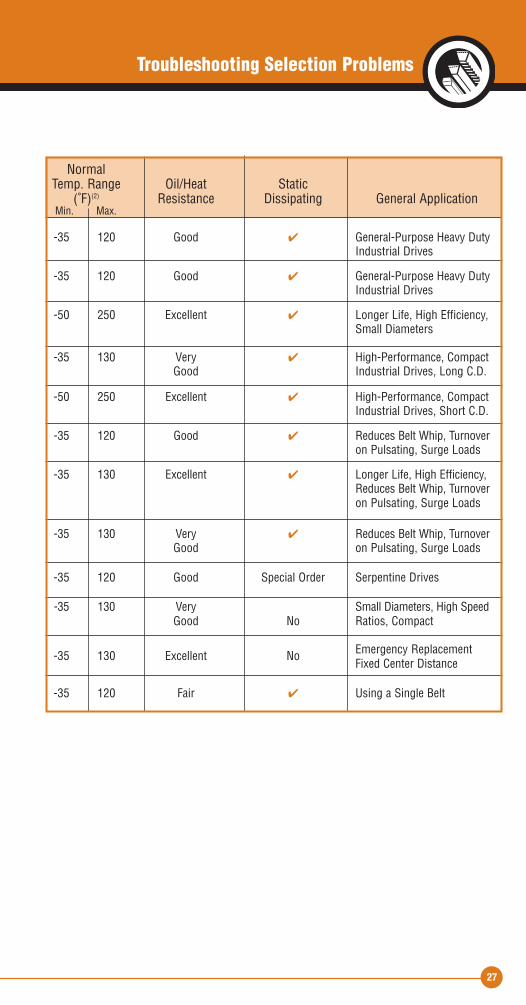
Normal Temp. Range Oil/Heat Static (˚F)(2) Resistance Dissipating General Application Min. Max.
-35 120 Good � General-Purpose Heavy Duty Industrial Drives
-35 120 Good � General-Purpose Heavy Duty Industrial Drives
-50 250 Excellent � Longer Life, High Efficiency, Small Diameters
-35 130 Very � High-Performance, Compact Good Industrial Drives, Long C.D.
-50 250 Excellent � High-Performance, Compact Industrial Drives, Short C.D.
-35 120 Good � Reduces Belt Whip, Turnover on Pulsating, Surge Loads
-35 130 Excellent � Longer Life, High Efficiency, Reduces Belt Whip, Turnover on Pulsating, Surge Loads
-35 130 Very � Reduces Belt Whip, Turnover Good on Pulsating, Surge Loads
-35 120 Good Special Order Serpentine Drives -35 130 Very Small Diameters, High Speed Good No Ratios, Compact
-35 130 Excellent No Emergency Replacement Fixed Center Distance
-35 120 Fair � Using a Single Belt
27
Troubleshooting Selection Problems

28
“Environmental Protection” can be as important for a V-belt as for humans. This sectiondeals with how to minimize adverse environmental conditions.
CSection 2Troubleshooting Environmental Problems
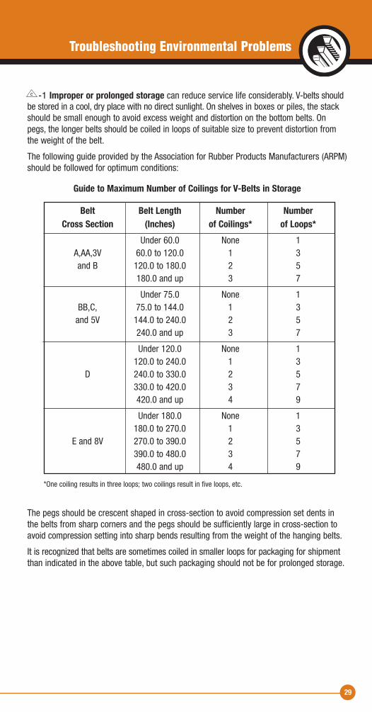
-1 Improper or prolonged storage can reduce service life considerably. V-belts shouldbe stored in a cool, dry place with no direct sunlight. On shelves in boxes or piles, the stackshould be small enough to avoid excess weight and distortion on the bottom belts. Onpegs, the longer belts should be coiled in loops of suitable size to prevent distortion fromthe weight of the belt.
The following guide provided by the Association for Rubber Products Manufacturers (ARPM)should be followed for optimum conditions:
Guide to Maximum Number of Coilings for V-Belts in Storage
Belt Belt Length Number Number Cross Section (Inches) of Coilings* of Loops* Under 60.0 None 1 A,AA,3V 60.0 to 120.0 1 3 and B 120.0 to 180.0 2 5 180.0 and up 3 7
Under 75.0 None 1 BB,C, 75.0 to 144.0 1 3 and 5V 144.0 to 240.0 2 5 240.0 and up 3 7
Under 120.0 None 1 120.0 to 240.0 1 3 D 240.0 to 330.0 2 5 330.0 to 420.0 3 7 420.0 and up 4 9
Under 180.0 None 1 180.0 to 270.0 1 3 E and 8V 270.0 to 390.0 2 5 390.0 to 480.0 3 7 480.0 and up 4 9
*One coiling results in three loops; two coilings result in five loops, etc.
The pegs should be crescent shaped in cross-section to avoid compression set dents inthe belts from sharp corners and the pegs should be sufficiently large in cross-section toavoid compression setting into sharp bends resulting from the weight of the hanging belts.
It is recognized that belts are sometimes coiled in smaller loops for packaging for shipmentthan indicated in the above table, but such packaging should not be for prolonged storage.
C
Troubleshooting Environmental Problems
29
30
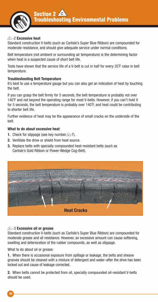
-2 Excessive heatStandard construction V-belts (such as Carlisle’s Super Blue Ribbon) are compounded formoderate resistance, and should give adequate service under normal conditions.
Belt temperature (not ambient or surrounding air temperature) is the determining factorwhen heat is a suspected cause of short belt life.
Tests have shown that the service life of a V-belt is cut in half for every 35˚F raise in belttemperature.
Troubleshooting Belt TemperatureIt’s best to use a temperature gauge but you can also get an indication of heat by touchingthe belt.
If you can grasp the belt firmly for 5 seconds, the belt temperature is probably not over140˚F and not beyond the operating range for most V-belts. However, if you can’t hold itfor 5 seconds, the belt temperature is probably over 140˚F, and heat could be contributingto shorter belt life.
Further evidence of heat may be the appearance of small cracks on the underside of thebelt.
What to do about excessive heat:1. Check for slippage (see key number -7).2. Ventilate the drive or shield from heat source.3. Replace belts with specially compounded heat-resistant belts (such as Carlisle’s Gold Ribbon or Power-Wedge Cog-Belt).
-3 Excessive oil or greaseStandard construction V-belts (such as Carlisle’s Super Blue Ribbon) are compounded formoderate grease and oil resistance. However, an excessive amount can cause softening,swelling and deterioration of the rubber compounds, as well as slippage.
What to do about oil or grease:
1. When there is occasional exposure from spillage or leakage, the belts and sheavegrooves should be cleaned with a mixture of detergent and water–after the drive has beenlocked out and cause of leakage corrected.
2. When belts cannot be protected from oil, specially compounded oil-resistant V-beltsshould be used.
C
C
Heat Cracks
A
CSection 2Troubleshooting Environmental Problems
31
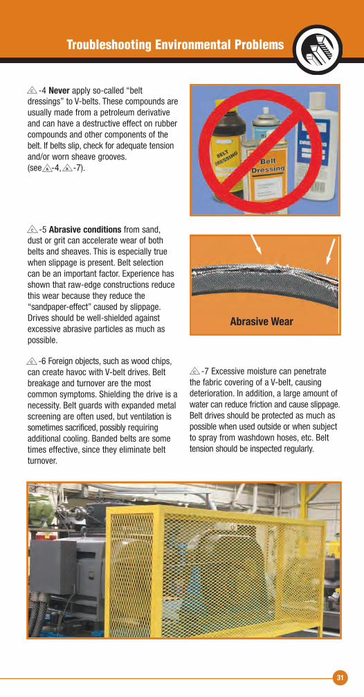
-4 Never apply so-called “belt dressings” to V-belts. These compounds areusually made from a petroleum derivativeand can have a destructive effect on rubbercompounds and other components of thebelt. If belts slip, check for adequate tensionand/or worn sheave grooves. (see -4, -7).
-5 Abrasive conditions from sand, dust or grit can accelerate wear of bothbelts and sheaves. This is especially truewhen slippage is present. Belt selection can be an important factor. Experience hasshown that raw-edge constructions reducethis wear because they reduce the “sandpaper-effect” caused by slippage.Drives should be well-shielded againstexcessive abrasive particles as much aspossible.
-6 Foreign objects, such as wood chips, can create havoc with V-belt drives. Beltbreakage and turnover are the most common symptoms. Shielding the drive is anecessity. Belt guards with expanded metalscreening are often used, but ventilation issometimes sacrificed, possibly requiring additional cooling. Banded belts are sometimes effective, since they eliminate beltturnover.
-7 Excessive moisture can penetrate the fabric covering of a V-belt, causing deterioration. In addition, a large amount ofwater can reduce friction and cause slippage.Belt drives should be protected as much aspossible when used outside or when subjectto spray from washdown hoses, etc. Belttension should be inspected regularly.
C
A A
C
C
C
Abrasive Wear
Troubleshooting Environmental Problems
32
When normal corrective measures as discussed in the previous sections do not producethe desired results, an inherent design problem may be the culprit. Solutions are best left upto the plant engineering department or a Certified Drive Specialist. However, the discussionpresented in this section will help identify symptoms caused by design problems.
Carlisle offers Drive Engineer, a new generation of analysis software that helps usersincrease their drive efficiency, drive life and overall knowledge of belt drives. DriveEngineer is a user friendly Windows®-based program that facilitates new drive selectionand existing drive analysis. The package includes information about horsepower capacity,warnings for drive limits, service factors, hub loads, bushings, diameters, center distanceand tensioning—in short, everything needed to design a maximum-efficiency drive system. Drive Engineer can be downloaded at carlislebelts.com
DSection 2Troubleshooting Design Problems
33
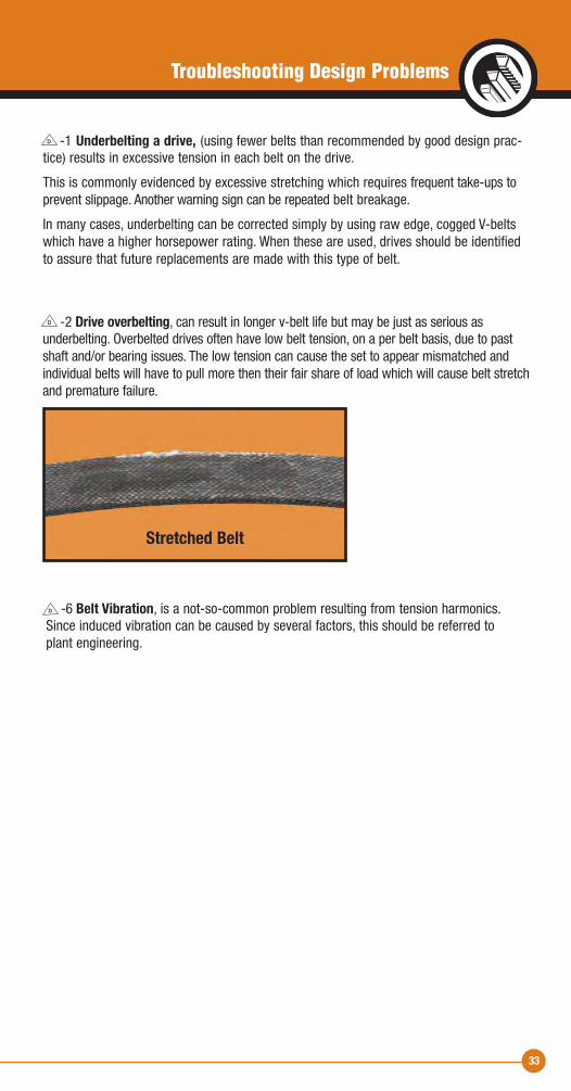
-1 Underbelting a drive, (using fewer belts than recommended by good design prac-tice) results in excessive tension in each belt on the drive.
This is commonly evidenced by excessive stretching which requires frequent take-ups toprevent slippage. Another warning sign can be repeated belt breakage.
In many cases, underbelting can be corrected simply by using raw edge, cogged V-beltswhich have a higher horsepower rating. When these are used, drives should be identifiedto assure that future replacements are made with this type of belt.
-2 Drive overbelting, can result in longer v-belt life but may be just as serious as underbelting. Overbelted drives often have low belt tension, on a per belt basis, due to pastshaft and/or bearing issues. The low tension can cause the set to appear mismatched andindividual belts will have to pull more then their fair share of load which will cause belt stretchand premature failure.
D
D
-6 Belt Vibration, is a not-so-common problem resulting from tension harmonics. Since induced vibration can be caused by several factors, this should be referred to plant engineering.
D
Troubleshooting Design Problems
Stretched Belt
34
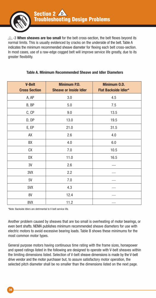
-3 When sheaves are too small for the belt cross-section, the belt flexes beyond its normal limits. This is usually evidenced by cracks on the underside of the belt. Table A indicates the minimum recommended sheave diameter for flexing each belt cross-section. In most cases, use of a raw-edge cogged belt will improve service life greatly, due to itsgreater flexibility.
Table A. Minimum Recommended Sheave and Idler Diameters
V-Belt Minimum P.D. Minimum O.D. Cross Section Sheave or Inside Idler Flat Backside Idler* A, AP 3.0 4.5
B, BP 5.0 7.5
C, CP 9.0 13.5
D, DP 13.0 19.5
E, EP 21.0 31.5
AX 2.6 4.0
BX 4.0 6.0
CX 7.0 10.5
DX 11.0 16.5
3V 2.6 __
3VX 2.2 __
5V 7.0 __
5VX 4.3 __
8V 12.4 __
8VX 11.2 __
*Note: Backside Idlers are detrimental to V-belt service life.
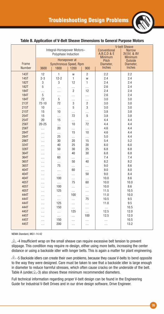
Another problem caused by sheaves that are too small is overheating of motor bearings, oreven bent shafts. NEMA publishes minimum recommended sheave diameters for use withelectric motors to avoid excessive bearing loads. Table B shows these minimums for themost common motor types.
General purpose motors having continuous time rating with the frame sizes, horsepowerand speed ratings listed in the following are designed to operate with V-belt sheaves withinthe limiting dimensions listed. Selection of V-belt sheave dimensions is made by the V-beltdrive vendor and the motor purchaser but, to assure satisfactory motor operation, theselected pitch diameter shall be no smaller than the dimensions listed on the next page.
D
DSection 2Troubleshooting Design Problems
35
Table B. Application of V-Belt Sheave Dimensions to General Purpose Motors
143T 12 1 w 2 2.2 2.2 145T 2-3 12-2 1 w 2.4 2.4 182T 3 3 12 1 2.4 2.4 182T 5 … … … 2.6 2.4 184T … … 2 12 2.4 2.4 184T 5 … … … 2.6 2.4 184T 72 5 … … 3.0 3.0 213T 72-10 72 3 2 3.0 3.0 215T 10 … 5 3 3.0 3.0 215T 15 10 … … 3.8 3.8 254T 15 … 72 5 3.8 3.8 254T 20 15 … … 4.4 4.4 256T 20-25 … 10 72 4.4 4.4 256T … 20 … … 4.6 4.4 284T … … 15 10 4.6 4.4 284T … 25 … … 5.0 4.4 286T … 30 20 15 5.4 5.2 324T … 40 25 20 6.0 6.0 326T … 50 30 25 6.8 6.8 364T … … 40 30 6.8 6.8 364T … 60 … … 7.4 7.4 365T … … 50 40 8.2 8.2 365T … 75 … … 9.0 8.6 404T … … 60 … 9.0 8.0 404T … … … 50 9.0 8.4 404T … 100 … … 10.0 8.6 405T … … 75 60 10.0 10.0 405T … 100 … … 10.0 8.6 405T … 125 … … 11.5 10.5 444T … … 100 … 11.0 10.0 444T … … … 75 10.5 9.5 444T … 125 … … 11.0 9.5 444T … 150 … … … 10.5 445T … … 125 … 12.5 12.0 445T … … … 100 12.5 12.0 445T … 150 … … … 10.5 445T … 200 … … … 13.2
NEMA Standard, MG1-14.42
-4 Insufficient wrap on the small sheave can require excessive belt tension to prevent slippage. This condition may require re-design, either using more belts, increasing the centerdistance or using a backside idler with longer belts. This is again a matter for plant engineering.
-5 Backside idlers can create their own problems, because they cause V-belts to bend oppositeto the way they were designed. Care must be taken to see that a backside idler is large enoughin diameter to reduce harmful stresses, which often cause cracks on the underside of the belt.Table A (under -3) also shows these minimum recommended diameters.
Full technical information regarding proper V-belt design can be found in the Engineering Guide for Industrial V-Belt Drives and in our drive design software, Drive Engineer.
FrameNumber
Integral-Horsepower Motors – Polyphase Induction
Horsepower at Synchronous Speed, Rpm
3600 1800 1200 900
V-belt Sheave Conventional Narrow A,B,C,D & E 3V,5V, & 8V Minimum Minimum Pitch Outside Diameter, Diameter, Inches Inches
D
D
D
Troubleshooting Design Problems
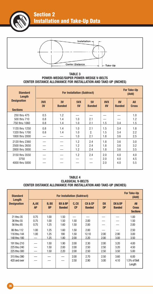
36
For Take-Up Standard For Installation (Subtract) (Add) LengthDesignation A, AX B, BX BX & BP C, CX CX & CP DX DX & DP All AP BP Banded CP Banded DP Banded Cross Sections 21 thru 35 0.75 1.00 1.50 — — — — 1.00 36 thru 55 0.75 1.00 1.50 1.50 2.00 — — 1.50 56 thru 85 0.75 1.25 1.60 1.50 2.00 — — 2.00
86 thru 112 1.00 1.25 1.60 1.50 2.00 — — 2.50 116 thru 144 1.00 1.25 180 1.50 12.10 2.00 2.90 3.00 148 thru 180 — 1.25 1.80 2.00 2.20 2.00 3.00 3.50
191 thru 210 — 1.50 1.90 2.00 2.30 2.00 3.20 4.00 225 thru 240 — 1.50 2.00 2.00 2.50 2.50 3.20 4.50 225 thru 300 — 1.50 2.20 2.00 2.50 2.50 3.50 5.00
315 thru 390 — — — 2.00 2.70 2.50 3.60 6.00 420 and over — — — 2.50 2.90 3.00 4.10 1.5% of Belt Length
For Take-Up Standard For Installation (Subtract) (Add) Length
Designation 3VX 3V 5VX 5V 8VX 8V All 3V Banded 5V Banded 8V Banded Cross Sections 250 thru 475 0.5 1.2 — — — — 1.0 500 thru 710 0.8 1.4 1.0 2.1 — — 1.2 750 thru 1060 0.8 1.4 1.0 2.1 1.5 3.4 1.5
1120 thru 1250 0.8 1.4 1.0 2.1 1.5 3.4 1.8 1320 thru 1700 0.8 1.4 1.0 2. 1.5 3.4 2.2 1800 thru 2000 — — 1.0 2.1 1.8 3.6 2.5
2120 thru 2360 — — 1.2 2.4 1.8 3.6 3.0 2500 thru 2650 — — 1.2 2.4 1.8 3.6 3.2 2800 thru 3000 — — 1.2 2.4 1.8 3.6 3.5
3150 thru 3550 — — 1.2 2.4 2.0 4.0 4.0 3750 — — — — 2.0 4.0 4.5 4000 thru 5000 — — — — 2.0 4.0 5.5
TABLE 3 POWER-WEDGE/SUPER POWER-WEDGE V-BELTS
CENTER DISTANCE ALLOWANCE FOR INSTALLATION AND TAKE-UP (INCHES)
TABLE 4 CLASSICAL V-BELTS
CENTER DISTANCE ALLOWANCE FOR INSTALLATION AND TAKE-UP (INCHES)
Section 2Installation and Take-Up Data
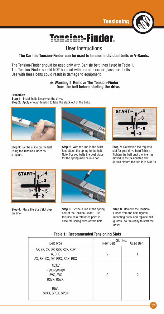
Table 1: Recommended Tensioning Slots Slot No. Belt Type New Belt Used Belt
AP, BP, CP, DP, RBP, RCP, RDP A, B, C 2 1 AX, BX. CX, DX, RBX, RCX, RDX
5V,8V R3V, R5V,R8V 5VX, 8VX 3 2 R3VX, R5VX, R5VL SPAX, SPBX, SPCX
37
User InstructionsThe Carlisle Tension-Finder can be used to tension individual belts or V-Bands.
The Tension-Finder should be used only with Carlisle belt lines listed in Table 1.The Tension-Finder should NOT be used with aramid cord or glass cord belts. Use with these belts could result in damage to equipment.
� Warning!! Remove The Tension-Finder from the belt before starting the drive.
ProcedureStep 1: Install belts loosely on the drive.Step 2: Apply enough tension to take the slack out of the belts.
Step 3: Scribe a line on the beltusing the Tension-Finder as a square.
Step 5: With the line in the StartSlot attach the spring to the belt.Note: For cog belts the best placefor the spring may be in a cog.
Step 7: Determine the requiredslot for your drive from Table 1.Tighten the belt until the line hasmoved to the designated slot. (In this picture the line is in Slot 3.)
Step 4: Place the Start Slot overthe line.
Step 6: Scribe a line at the springend of the Tension-Finder. Usethis line as a reference point incase the spring slips off the belt.
Step 8: Remove the Tension-Finder from the belt, tightenmounting bolts, and replace beltguards. You’re ready to start thedrive!
Tensioning
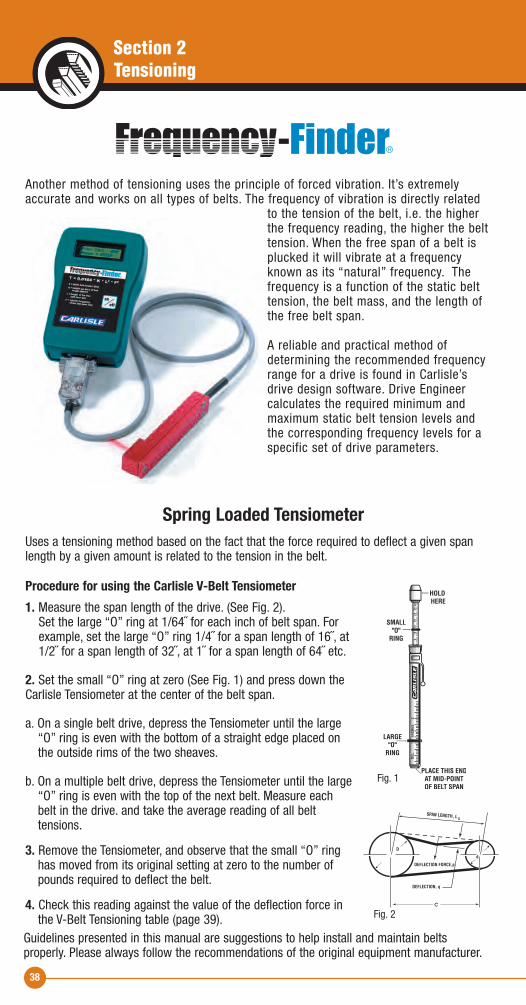
Another method of tensioning uses the principle of forced vibration. It’s extremelyaccurate and works on all types of belts. The frequency of vibration is directly related
to the tension of the belt, i.e. the higherthe frequency reading, the higher the belttension. When the free span of a belt isplucked it will vibrate at a frequencyknown as its “natural” frequency. Thefrequency is a function of the static belttension, the belt mass, and the length ofthe free belt span.
A reliable and practical method of determining the recommended frequencyrange for a drive is found in Carlisle’sdrive design software. Drive Engineer calculates the required minimum andmaximum static belt tension levels andthe corresponding frequency levels for aspecific set of drive parameters.
Uses a tensioning method based on the fact that the force required to deflect a given spanlength by a given amount is related to the tension in the belt.
Procedure for using the Carlisle V-Belt Tensiometer1. Measure the span length of the drive. (See Fig. 2). Set the large “O” ring at 1/64˝ for each inch of belt span. For example, set the large “O” ring 1/4˝ for a span length of 16˝, at 1/2˝ for a span length of 32˝, at 1˝ for a span length of 64˝ etc.
2. Set the small “O” ring at zero (See Fig. 1) and press down theCarlisle Tensiometer at the center of the belt span.
a. On a single belt drive, depress the Tensiometer until the large “O” ring is even with the bottom of a straight edge placed on the outside rims of the two sheaves.
b. On a multiple belt drive, depress the Tensiometer until the large “O” ring is even with the top of the next belt. Measure each belt in the drive. and take the average reading of all belt tensions.
3. Remove the Tensiometer, and observe that the small “O” ring has moved from its original setting at zero to the number of pounds required to deflect the belt.
4. Check this reading against the value of the deflection force in the V-Belt Tensioning table (page 39).
SPAN LENGTH, L
C
S
DEFLECTION FORCE,p
DEFLECTION, q
D
d
Fig. 2
Section 2Tensioning
Spring Loaded Tensiometer
Guidelines presented in this manual are suggestions to help install and maintain belts properly. Please always follow the recommendations of the original equipment manufacturer.
38
Fig. 1
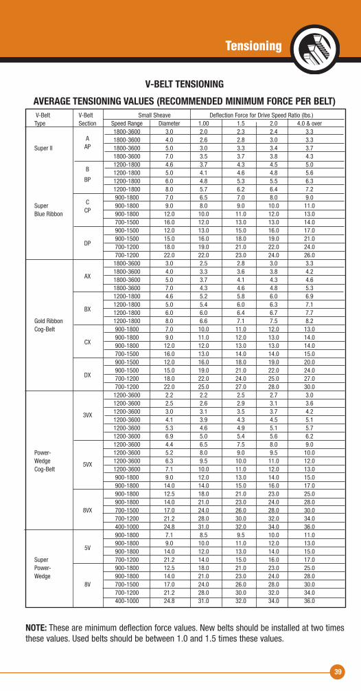
39
V-BELT TENSIONING AVERAGE TENSIONING VALUES (RECOMMENDED MINIMUM FORCE PER BELT)
V-Belt V-Belt Small Sheave Deflection Force for Drive Speed Ratio (lbs.) Type Section Speed Range Diameter 1.00 1.5 2.0 4.0 & over 1800-3600 3.0 2.0 2.3 2.4 3.3 A 1800-3600 4.0 2.6 2.8 3.0 3.3 Super ll AP 1800-3600 5.0 3.0 3.3 3.4 3.7 1800-3600 7.0 3.5 3.7 3.8 4.3 1200-1800 4.6 3.7 4.3 4.5 5.0 B 1200-1800 5.0 4.1 4.6 4.8 5.6 BP 1200-1800 6.0 4.8 5.3 5.5 6.3 1200-1800 8.0 5.7 6.2 6.4 7.2 900-1800 7.0 6.5 7.0 8.0 9.0 Super C 900-1800 9.0 8.0 9.0 10.0 11.0 Blue Ribbon CP 900-1800 12.0 10.0 11.0 12.0 13.0 700-1500 16.0 12.0 13.0 13.0 14.0 900-1500 12.0 13.0 15.0 16.0 17.0 900-1500 15.0 16.0 18.0 19.0 21.0 DP 700-1200 18.0 19.0 21.0 22.0 24.0 700-1200 22.0 22.0 23.0 24.0 26.0 1800-3600 3.0 2.5 2.8 3.0 3.3 1800-3600 4.0 3.3 3.6 3.8 4.2 AX 1800-3600 5.0 3.7 4.1 4.3 4.6 1800-3600 7.0 4.3 4.6 4.8 5.3 1200-1800 4.6 5.2 5.8 6.0 6.9 1200-1800 5.0 5.4 6.0 6.3 7.1 BX 1200-1800 6.0 6.0 6.4 6.7 7.7 Gold Ribbon 1200-1800 8.0 6.6 7.1 7.5 8.2 Cog-Belt 900-1800 7.0 10.0 11.0 12.0 13.0 900-1800 9.0 11.0 12.0 13.0 14.0 CX 900-1800 12.0 12.0 13.0 13.0 14.0 700-1500 16.0 13.0 14.0 14.0 15.0 900-1500 12.0 16.0 18.0 19.0 20.0 900-1500 15.0 19.0 21.0 22.0 24.0 DX 700-1200 18.0 22.0 24.0 25.0 27.0 700-1200 22.0 25.0 27.0 28.0 30.0 1200-3600 2.2 2.2 2.5 2.7 3.0 1200-3600 2.5 2.6 2.9 3.1 3.6 3VX 1200-3600 3.0 3.1 3.5 3.7 4.2 1200-3600 4.1 3.9 4.3 4.5 5.1 1200-3600 5.3 4.6 4.9 5.1 5.7 1200-3600 6.9 5.0 5.4 5.6 6.2 1200-3600 4.4 6.5 7.5 8.0 9.0 Power- 1200-3600 5.2 8.0 9.0 9.5 10.0 Wedge 5VX 1200-3600 6.3 9.5 10.0 11.0 12.0 Cog-Belt 1200-3600 7.1 10.0 11.0 12.0 13.0 900-1800 9.0 12.0 13.0 14.0 15.0 900-1800 14.0 14.0 15.0 16.0 17.0 900-1800 12.5 18.0 21.0 23.0 25.0 900-1800 14.0 21.0 23.0 24.0 28.0 8VX 700-1500 17.0 24.0 26.0 28.0 30.0 700-1200 21.2 28.0 30.0 32.0 34.0 400-1000 24.8 31.0 32.0 34.0 36.0 900-1800 7.1 8.5 9.5 10.0 11.0 900-1800 9.0 10.0 11.0 12.0 13.0 5V 900-1800 14.0 12.0 13.0 14.0 15.0 Super 700-1200 21.2 14.0 15.0 16.0 17.0 Power- 900-1800 12.5 18.0 21.0 23.0 25.0 Wedge 900-1800 14.0 21.0 23.0 24.0 28.0 8V 700-1500 17.0 24.0 26.0 28.0 30.0 700-1200 21.2 28.0 30.0 32.0 34.0 400-1000 24.8 31.0 32.0 34.0 36.0
NOTE: These are minimum deflection force values. New belts should be installed at two timesthese values. Used belts should be between 1.0 and 1.5 times these values.
Tensioning
40
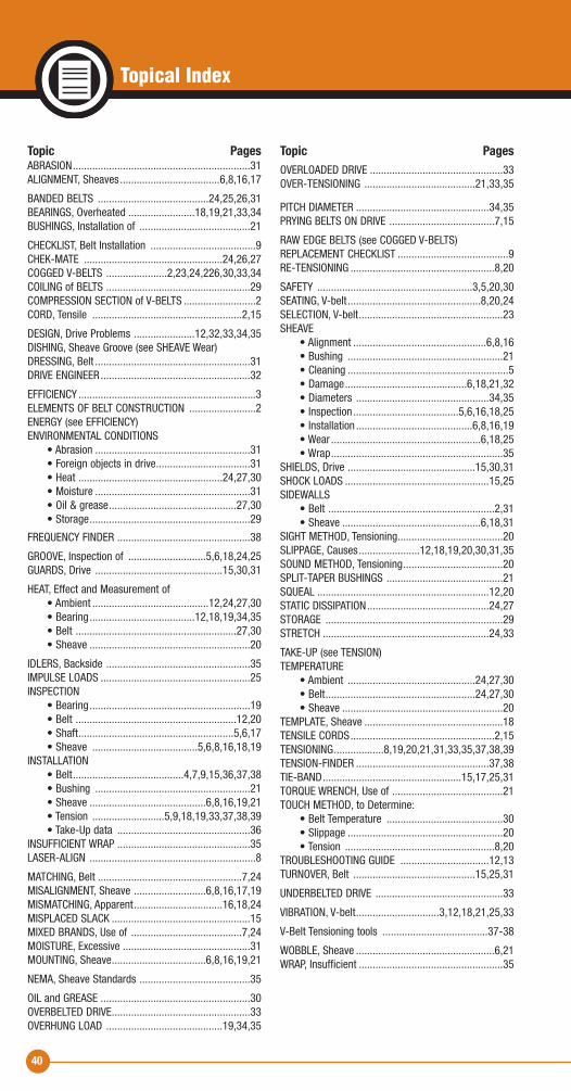
Topical Index
Topic PagesABRASION................................................................31ALIGNMENT, Sheaves....................................6,8,16,17
BANDED BELTS ........................................24,25,26,31BEARINGS, Overheated ........................18,19,21,33,34BUSHINGS, Installation of ........................................21
CHECKLIST, Belt Installation ......................................9CHEK-MATE ..................................................24,26,27COGGED V-BELTS ......................2,23,24,226,30,33,34COILING of BELTS ....................................................29COMPRESSION SECTION of V-BELTS ..........................2CORD, Tensile ......................................................2,15
DESIGN, Drive Problems ......................12,32,33,34,35DISHING, Sheave Groove (see SHEAVE Wear)DRESSING, Belt ........................................................31DRIVE ENGINEER......................................................32
EFFICIENCY ................................................................3ELEMENTS OF BELT CONSTRUCTION ........................2ENERGY (see EFFICIENCY)ENVIRONMENTAL CONDITIONS • Abrasion ........................................................31 • Foreign objects in drive..................................31 • Heat ....................................................24,27,30 • Moisture ........................................................31 • Oil & grease..............................................27,30 • Storage..........................................................29
FREQUENCY FINDER ................................................38
GROOVE, Inspection of ............................5,6,18,24,25GUARDS, Drive ..............................................15,30,31
HEAT, Effect and Measurement of • Ambient ..........................................12,24,27,30 • Bearing......................................12,18,19,34,35 • Belt ..........................................................27,30 • Sheave ..........................................................20
IDLERS, Backside ....................................................35IMPULSE LOADS ......................................................25INSPECTION • Bearing..........................................................19 • Belt ..........................................................12,20 • Shaft........................................................5,6,17 • Sheave ......................................5,6,8,16,18,19INSTALLATION • Belt........................................4,7,9,15,36,37,38 • Bushing ........................................................21 • Sheave ..........................................6,8,16,19,21 • Tension ..........................5,9,18,19,33,37,38,39 • Take-Up data ................................................36INSUFFICIENT WRAP ................................................35LASER-ALIGN ............................................................8
MATCHING, Belt ....................................................7,24MISALIGNMENT, Sheave ..........................6,8,16,17,19MISMATCHING, Apparent................................16,18,24MISPLACED SLACK ..................................................15MIXED BRANDS, Use of ........................................7,24MOISTURE, Excessive ..............................................31MOUNTING, Sheave..................................6,8,16,19,21
NEMA, Sheave Standards ........................................35
OIL and GREASE ......................................................30OVERBELTED DRIVE..................................................33OVERHUNG LOAD ..........................................19,34,35
Topic PagesOVERLOADED DRIVE ................................................33OVER-TENSIONING ........................................21,33,35
PITCH DIAMETER ................................................34,35PRYING BELTS ON DRIVE ......................................7,15
RAW EDGE BELTS (see COGGED V-BELTS)REPLACEMENT CHECKLIST ........................................9RE-TENSIONING ....................................................8,20
SAFETY ........................................................3,5,20,30SEATING, V-belt ................................................8,20,24SELECTION, V-belt....................................................23SHEAVE • Alignment ................................................6,8,16 • Bushing ........................................................21 • Cleaning ..........................................................5 • Damage............................................6,18,21,32 • Diameters ................................................34,35 • Inspection ......................................5,6,16,18,25 • Installation ..........................................6,8,16,19 • Wear ......................................................6,18,25 • Wrap..............................................................35SHIELDS, Drive ..............................................15,30,31SHOCK LOADS ....................................................15,25SIDEWALLS • Belt ............................................................2,31 • Sheave ..................................................6,18,31SIGHT METHOD, Tensioning......................................20SLIPPAGE, Causes......................12,18,19,20,30,31,35SOUND METHOD, Tensioning....................................20SPLIT-TAPER BUSHINGS ..........................................21SQUEAL ..............................................................12,20STATIC DISSIPATION............................................24,27STORAGE ................................................................29STRETCH ............................................................24,33
TAKE-UP (see TENSION)TEMPERATURE • Ambient ..............................................24,27,30 • Belt......................................................24,27,30 • Sheave ..........................................................20TEMPLATE, Sheave ..................................................18TENSILE CORDS....................................................2,15TENSIONING..................8,19,20,21,31,33,35,37,38,39TENSION-FINDER ................................................37,38TIE-BAND..................................................15,17,25,31TORQUE WRENCH, Use of ........................................21TOUCH METHOD, to Determine: • Belt Temperature ..........................................30 • Slippage ........................................................20 • Tension ......................................................8,20TROUBLESHOOTING GUIDE ................................12,13TURNOVER, Belt ............................................15,25,31
UNDERBELTED DRIVE ..............................................33
VIBRATION, V-belt..............................3,12,18,21,25,33
V-Belt Tensioning tools ......................................37-38
WOBBLE, Sheave ..................................................6,21WRAP, Insufficient ....................................................35
The Right Belt for the Job
1
2
3
4
5
6
7
8
9
10
11
12
13
14
3
5
67
8
9
10
1312
The Right Belt for the Job
CarlisleBelts.com CarlisleBelts.com
*
*
*
*
Safety Note �WARNING
Safety must be considered a basic factor in machinery operation at alltimes. Most accidents are the result of carelessness or negligence.Power transmission products such as those listed in this catalog arepotentially dangerous and must be guarded by the contractor, installer,purchaser, owner, and user as required by applicable laws, regu lations,standards, and good safety practice.
Failure to follow proper procedures for installation, care, maintenanceand storage of products may result in failure to perform properly andmay result in damage to property and serious bodily injury. Make surethat the product selected for any application is recommended for thatservice.
It is the responsibility of the contractor, installer, purchaser, owner, anduser to install, maintain, and operate the parts or componentsmanufactured and supplied by The Carlstar Group in such a manner asto comply with all occupational safety laws, federal, state and locallaws, ordinances, regulations, etc.
CAUTION
Guards, access doors, and covers must be securely fastenedbefore operating any equipment. If parts are to be inspected,cleaned, observed, or general maintenance performed, the motordriving the part or components is to be locked out electrically insuch a manner that it cannot be started by anyone. Failure to followthese instructions may result in property damage, personal injury,or death.
AIRCRAFT WARNING!
Carlisle belts and pulleys are not designed or intended for aircraft use.Do not use Carlisle belts on aircraft propeller, rotor or accessory drives.Do not use Carlisle belts on helicopters or private, commercial, orultralight aircraft.
1
2
4
14
* available in construction
Gold Ribbon® Cog-Belt® (AX,BX,CX,DX)The Energy Saver! More efficient than ordinary belts. The finest classical V-belt available.
Gold Ribbon® Cog-Band® (RBX,RCX,RDX)A unique combination of our energy saving Cog-Belt and the banded concept.
Power-Wedge® Cog-Belt® (3VX,5VX,8VX) Space saving V-Belt transmits higher HP andprovides longer life for maximum savings.
Metric Power-Wedge® Cog-Belt®
(SPZX, SPAX, SPBX, SPCX) Compact and efficient operation for drives that require metric cross sections. Reduces weight and overhung load.
Power-Wedge® Cog-Band®
(R3VX, R5VX) Power Wedge Cog-Belt in banded design. Compact and efficient. Eliminateswhip and turnover on narrow drives.
Super Power-Wedge® V-Belt (5V,8V)Designed for lower cost, more compact multiple-belt drives.
Wedge-Band® (R3V, R5V, R8V)Carlisle's Power-Wedge belt in banded design. Eliminates whip and turnover on narrow drives.
Wedge-Band® Chipper Drive Belt (R5VL) Specially designed and constructed to meet the unique demands of the forest products industry. Ideally suited for chipper saws, debarker drives, head rigs and hogs.
Super Blue Ribbon® V-Belt (AP,BP,CP,DP) The finest wrapped belt in the industry.
Super II® V- Belt (A,B,C)The revolutionary raw-edge® belt from Carlisle that blows the cover off conventional wrapped belts with its unique construction.
Super Vee-Band ® (RBP,RCP,RDP) Carlisle’s Super Blue Ribbon V-Belt in banded design. Eliminates belt whip and turnover on conventional drives.
Double-Angle Belt (AA,BB,CC)Designed for use on serpentine type drive applications.
Durapower® ll (Raw Edge) FHP Light Duty V-BeltLonger belt life and improved performance.
Vee-Rib Belt (J) Increased horsepower in two thirds the space required for normal belts.
11
®
*
*
©The Carlstar Group LLC. All rights reserved. IND-L-1501
U.S.A. Customer Service: 866-773-2926
CANADA Customer Service: 866-797-2358
Industrial V-Belt DrivesService Manual