Embed Size (px)
Citation preview

Influence of Back Shroud Shape on Performance and Internal Flow of Fluid Food Pump
Toru Shigemitsu1*, Takumi Matsubara2, Masahiro Sakaguchi2, Junichiro Fukutomi1
ISROMAC 2016
International
Symposium on
Transport
Phenomena and
Dynamics of Rotating
Machinery
Hawaii, Honolulu
April 10-15, 2016
Abstract
Fluid machineries for fluid food have been used in wide variety of field i.e. transportation, filling, and
improvement of quality of fluid food. Although, flow conditions of these are quite complicated because
fluid food is different from water. Therefore, a design method based on the internal flow conditions is not
conducted. In this research, a centrifugal pump having small number of blade was used to decrease
shear loss and keep wide flow passage. Furthermore, a semi-open and two types of open impellers were
prepared to investigate the influence of back shroud shapes on the performance and internal flow. The
head of the pump using the open impeller was larger than that using the semi-open impeller because of
the difference of the back shroud shape. In this paper, the internal flow conditions near the hub of the
centrifugal pump having semi-open and open impellers were investigated by the numerical analysis
results.
Keywords
Centrifugal pump, Back shroud, Performance, Internal flow
1 Institute of Technology and Science, Tokushima University,Tokushima, Japan 2 Graduate School of Advanced Technology and Science, Tokushima University, Tokushima,Japan
*Corresponding author: [email protected]
INTRODUCTION
It is said that world population will increase to 10 billion in several decades, so large quantities and stable supply of food are needed. Furthermore, a concern of food safety is also increasing nowadays. Fluid machines for fluid food have been used in wide variety of fields i.e. transportation, filling, and improvement of quality of fluid food. Flow conditions of those fluid machines are very complex and unclear because subject fluid of these fluid machines is fluid different from air and water. Ota et al. clarified influences of a tip clearance, a blade outlet angle and a blade number on the performance of a centrifugal pump using oil [1]-[3]. On the other hand, internal flow condition of the pump using fluid food is not known, however, there are a few report related to the flow condition in a pipe, where fluid food flows [4],[5]. Therefore, the design based on internal flow conditions is not conducted at present. The important issues requested for the fluid food pump are transportation performance, suction ability, flow rate control, quality maintenance, sanitary condition and so on. There are many kinds of the fluid food transportation pumps depending on the characteristics of fluid, i.e. a sanitary pump made from stainless steel, a screw pump and so on. A centrifugal pump was adopted as a fluid food pump in this research because the stable continuous transportation of fluid food was possible and the structure was simple compared to a positive displacement pump. The purposes of this research are to establish pump design method based on the internal flow condition of each fluid food and to make sure of the boundary line of fluid food, the centrifugal pump can apply
to.
In this research, a centrifugal pump having small number of blade was used to decrease shear loss and keep a wide flow passage. Moreover, a semi-open impeller and two types of open impellers were adopted for this centrifugal pump to invetigate the back shroud shape influence on the performance and internal flow. Furthermore, the blade inlet
and outlet angles were set as β1=β2=90° to facilitate the maintenance and cleaning in the pump. We investigated the effect of a tip clearance and viscosity on the performance and internal flow condition of the fluid food pump for low viscous fluid food in the previous research [6],[7]. Then, large vortex and flow separation were observed on a suction surface of a blade and strong unsteady flow could be generated in the pump [8]. The flow conditions near the hub need to be investigated because the open impellers were adopted for some of the fluid food pump. Furthermore, it is important to clarify the influence of the back shroud shape on the performance and flow condition to improve the performance of the fluid food pump. Then, the flow condition near the hub of the centrifugal pump having the semi-open and open impellers were investigated by the numerical analysis results.
In this paper, the performances of the centrifugal pump having the semi-open and open impellers were clarifed by the experimental results. In addition to that, the flow conditions near the hub were shown based on the numerical analysis results.
1. EXPERIMENTAL APPARATUS AND METHOD
A specification of the pump, i.e. the design head, flow rate
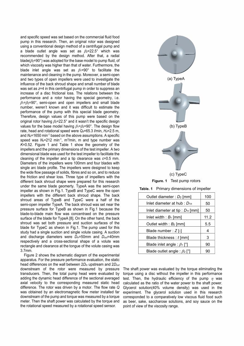
and specific speed was set based on the commercial fluid food pump in this research. Then, an original rotor was designed using a conventional design method of a centrifugal pump and
a blade outlet angle was set as β2=22.5° which was recommended by the design method. After that, a radial
blade(β2=90°) was adopted for the base model to pump fluid, of which viscosity was higher than that of water. Furthermore, the
blade inlet angle was set as β1=90° to facilitate the maintenance and cleaning in the pump. Moreover, a semi-open and two types of open impellers were used to investigate the influence of the back shroud shape and small number of blade was set as z=4 in this centrifugal pump in order to suppress an increase of a disc frictional loss. The relations between the performance and a rotor having the special geometry, i.e.
β1=β2=90°, semi-open and open impellers and small blade number, weren’t known and it was difficult to estimate the performance of the pump with this special blade geometry. Therefore, design values of this pump were based on the
original rotor having β2=22.5° and it wasn’t the specific design
values for the base model having β1=β2=90°. The design flow rate, head and rotational speed were Qd=65.3 l/min, Hd=2.5 m, and Nd=1650 min-1 based on the above assumptions. A specific speed was Ns=212 min-1, m3/min, m and type number was K=0.52. Figure 1 and Table 1 show the geometry of the impellers and the primary dimensions of the test impeller. A two dimensional blade was used for the test impeller to facilitate the cleaning of the impeller and a tip clearance was c=0.5 mm. Diameters of the impellers were 100mm and four blades with single arc blade profile. The impellers were designed to keep the wide flow passage of solids, fibres and so on, and to reduce the friction and shear loss. Three type of impelllers with the different back shroud shape were prepared for this research under the same blade geomerty. TypeA was the semi-open impeller as shown in Fig.1. TypeB and TypeC were the open impellers with the different back shroud shape. The back shroud areas of TypeB and TypeC were a half of the semi-open impeller TypeA. The back shroud was set near the pressure surface for TypeB as shown in Fig.1 because the blade-to-blade main flow was concentraed on the pressure surface of the blade for TypeA [8]. On the other hand, the back shroud was set both pressure and suction surfaces of the blade for TypeC as shwon in Fig.1. The pump used for this study had a single suction and single volute casing. A suction and discharge diameters were Din=50mm and Dout=40mm respectively and a cross-sectional shape of a volute was rectangle and clearance at the tongue of the volute casing was 3.7mm.
Figure 2 shows the schematic diagram of the experimental apparatus. For the pressure performance evaluation, the static head differences on the wall between 2Din upstream and 2Dout downstream of the rotor were measured by pressure transducers. Then, the total pump head were evaluated by adding the dynamic head difference of the sectional averaged axial velocity to the corresponding measured static head difference. The rotor was driven by a motor. The flow rate Q was obtained by an electromagnetic flow meter installed far downstream of the pump and torque was measured by a torque meter. Then the shaft power was calculated by the torque and the rotational speed measured by a rotational speed sensor.
The shaft power was evaluated by the torque eliminating the torque using a disc without the impeller in this performance
test. Then, the hydraulic efficiency of the pump η was calculated as the ratio of the water power to the shaft power. Glycerol solution(40% volume density) was used in the experiment. The glycerol solution used in this research corresponded to a comparatively low viscous fluid food such as beer, sake, saccharose solutions, and soy sauce on the point of view of the viscosity range.
Figure. 1 Test pump rotors
(a) TypeA
(b) TypeB
(c) TypeC
Outlet diameter : D2 [mm] 100
Inlet diameter at hub : D1h 50
Inlet diameter at tip : D1t [mm] 50
Inlet width : B1 [mm] 11.2
Outlet width : B2 [mm] 5.5
Blade number : Z [-] 4
Blade thickness : t [mm] 3
Blade inlet angle : β1 [°] 90
Blade outlet angle : β2 [°] 90
Table. 1 Primary dimensions of impeller
2. NUMERICAL ANALYSIS CONDITION
A numerical flow analysis was conducted to investigate the internal flow condition in detail. In the numerical analysis, the commercial software ANSYS-CFX was used and the numerical analysis was conducted with a numerical model which was the same with the test section of the experiment under the three dimensional unsteady condition. Fluid was assumed to be incompressible and isothermal water and the equation of the mass flow conservation and Reynolds Averaged Navier-Stokes equations were solved by the finite volume method. The standard wall function was utilized near the wall and SST model was used as the turbulence model. The numerical analysis was conducted at a design flow rate Qd and kinematic viscosity and density of the fluid were changed from water to simulate the glycerol solution used for the experiment. Figure 3 show the numerical grids used for the numerical analysis. An inlet boundary was 5Din upstream of the test section and an outlet was 5Dout downstream of it. A tip clearance was set c=0.5mm as the same with the experimental apparatus. The constant velocity and constant pressure were given as the boundary conditions at the inlet and outlet respectively. Mesh numbers of the numerical domain was about 6.0×10⁶ grid points. The coupling between the rotor and casing was accomplished by the Transient Rotor Stator. The time step number per one rotor rotation was 180 and the time step was t=2.02×10⁻⁴ s. The data of one rotor rotation were obtained after 6 rotor rotations in unsteady numerical analysis.
3. RESULTS AND DISCUSSIONS
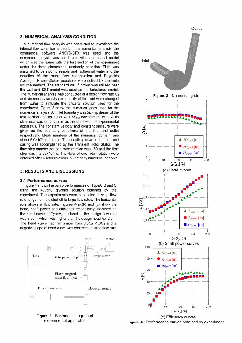
3.1 Performance curves Figure 4 shows the pump performances of TypeA, B and C
using the 40vol% glycerol solution obtained by the
experiment. The experiments were conducted in wide flow
rate range from the shut-off to large flow rates. The horizontal
axis shows a flow rate. Figures 4(a),(b) and (c) show the
head, shaft power and efficiency respectively. Focused on
the head curve of TypeA, the head at the design flow rate
was 3.55m, which was higher than the design head Hd=2.5m.
The head curve had flat shape from 0.5Qd -1.0Qd and a
negative slope of head curve was observed in large flow rate
0
20
40
60
80
100
0 50 100 150 200
η [
%]
Q/Qd [%]
Q/Qd [%]
0
0.03
0.06
0.09
0.12
0.15
0 50 100 150 200
L [
kW
]
Inlet
Outlet
Figure. 3 Numerical grids
Figure. 2 Schematic diagram of experimental apparatus
Ancillary pump
Torque meter
Flow control valve
Electro-magnetic
water flow meter
Static pressure tapTank
Pump Motor
Booster pump
H [
m]
Q/Qd [%]
0
1
2
3
4
5
H [
m]
Q/Qd [%]
0
1
2
3
4
5
0 50 100 150 200
H [
m]
▲ HTypeA [m]
● HTypeB [m]
■ HTypeC [m]
Figure. 4 Performance curves obtained by experiment
(a) Head curves
(b) Shaft power curves
(c) Efficiency curves
▲ LTypeA [m]
● LTypeB [m]
■ LTypeC [m]
▲ ηTypeA [m]
● ηTypeB [m]
■ ηTypeC [m]
region. The head of TypeB and C were larger than that of
TypeA because the circumferential velocity increased by the
back shroud edge. The shaft power increased with the
increase of flow rate and showed the minimum value at shut-off flow rate for all types. On the other hand, the shaft powers of TypeB and C were larger than that of TypeA in all
flow rates. The maximum efficiency ηmax=56.5% was obtained at 1.4Qd for TypeA and the maximum efficiency of TypeB and
TypeC were ηmax=49.2 and 49.7% respectively at 1.8Qd. It was considered that the efficiency of open impellers were lower than that of semi-open impeller because of the flow from the clearance of the back shroud. The performances of TypeB and C with the different back shroud shape were almost the same and the influence of the back shroud shape on the performance was small.
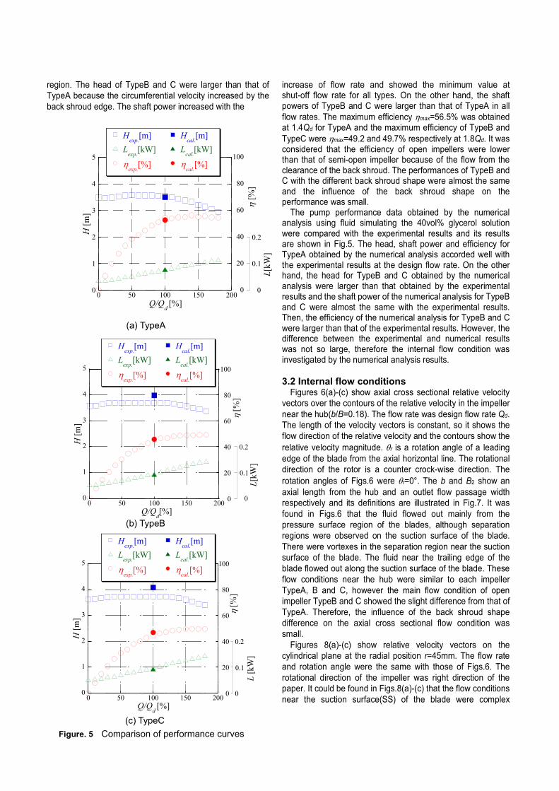
The pump performance data obtained by the numerical analysis using fluid simulating the 40vol% glycerol solution were compared with the experimental results and its results are shown in Fig.5. The head, shaft power and efficiency for TypeA obtained by the numerical analysis accorded well with the experimental results at the design flow rate. On the other hand, the head for TypeB and C obtained by the numerical analysis were larger than that obtained by the experimental results and the shaft power of the numerical analysis for TypeB and C were almost the same with the experimental results. Then, the efficiency of the numerical analysis for TypeB and C were larger than that of the experimental results. However, the difference between the experimental and numerical results was not so large, therefore the internal flow condition was investigated by the numerical analysis results.
3.2 Internal flow conditions
Figures 6(a)-(c) show axial cross sectional relative velocity
vectors over the contours of the relative velocity in the impeller
near the hub(b/B=0.18). The flow rate was design flow rate Qd.
The length of the velocity vectors is constant, so it shows the
flow direction of the relative velocity and the contours show the
relative velocity magnitude. θr is a rotation angle of a leading
edge of the blade from the axial horizontal line. The rotational
direction of the rotor is a counter crock-wise direction. The
rotation angles of Figs.6 were θr=0°. The b and B2 show an
axial length from the hub and an outlet flow passage width
respectively and its definitions are illustrated in Fig.7. It was
found in Figs.6 that the fluid flowed out mainly from the
pressure surface region of the blades, although separation
regions were observed on the suction surface of the blade.
There were vortexes in the separation region near the suction
surface of the blade. The fluid near the trailing edge of the
blade flowed out along the suction surface of the blade. These
flow conditions near the hub were similar to each impeller
TypeA, B and C, however the main flow condition of open
impeller TypeB and C showed the slight difference from that of
TypeA. Therefore, the influence of the back shroud shape
difference on the axial cross sectional flow condition was
small.
Figures 8(a)-(c) show relative velocity vectors on the
cylindrical plane at the radial position r=45mm. The flow rate
and rotation angle were the same with those of Figs.6. The
rotational direction of the impeller was right direction of the
paper. It could be found in Figs.8(a)-(c) that the flow conditions
near the suction surface(SS) of the blade were complex
H [
m]
Q/Qd [%]
L[k
W]
0.2
0.1
00
1
2
3
4
5
0 50 100 150 2000
20
40
60
80
100
η [
%]
0 50 100 150 200
L[k
W]
0.2
0.1
0
Q/Qd[%]
0
1
2
3
4
5
H [
m]
0
20
40
60
80
100
η [
%]
0
1
2
3
4
5
H [
m]
Q/Qd [%]
0
20
40
60
80
100
0 50 100 150 200
η [
%]
L [
kW
]
0
0.1
0.2
Figure. 5 Comparison of performance curves
(a) TypeA
(b) TypeB
(c) TypeC
Hexp.
[m]
Lexp.
[kW]
ηexp.
[%]
Hcal.
[m]
Lcal.
[kW]
ηcal.
[%]
Hexp.
[m]
Lexp.
[kW]
ηexp.
[%]
Hcal.
[m]
Lcal.
[kW]
ηcal.
[%]
Hexp.
[m]
Lexp.
[kW]
ηexp.
[%]
Hcal.
[m]
Lcal.
[kW]
ηcal.
[%]
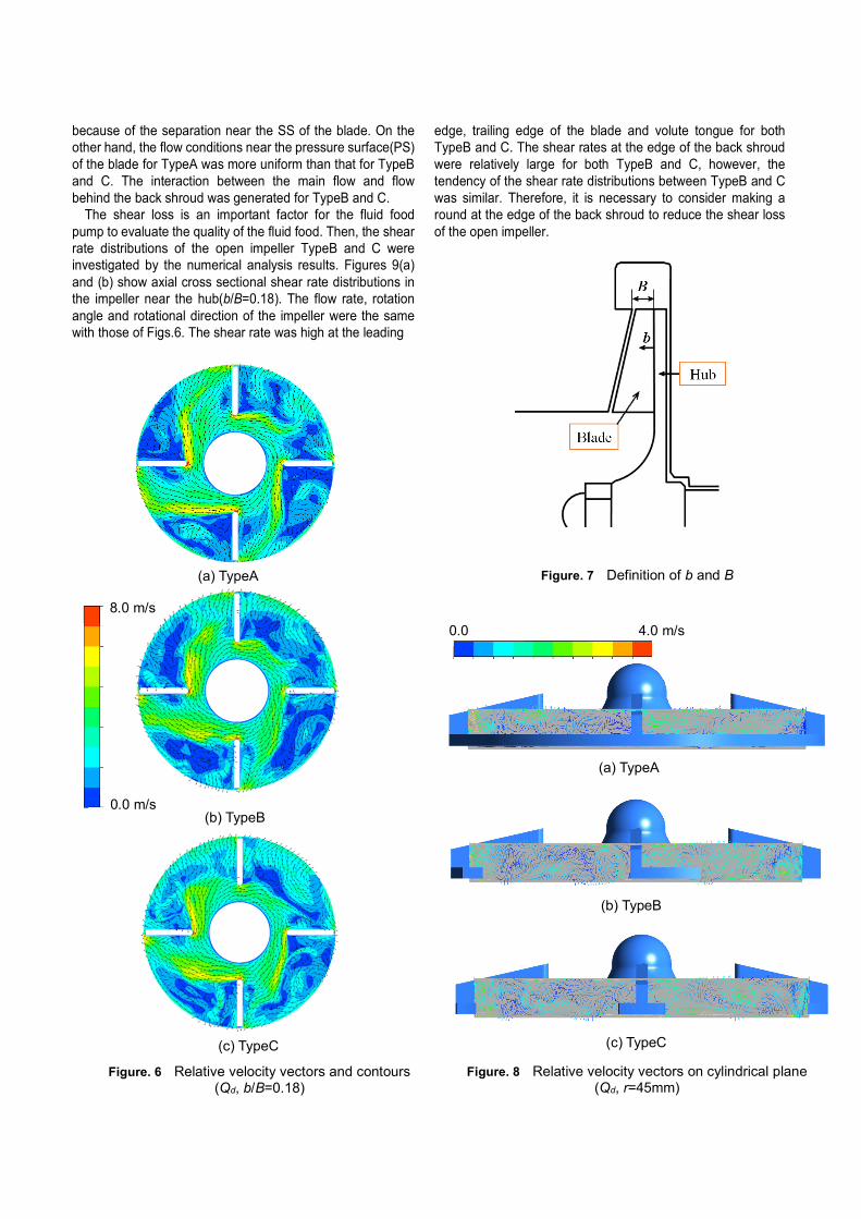
because of the separation near the SS of the blade. On the
other hand, the flow conditions near the pressure surface(PS)
of the blade for TypeA was more uniform than that for TypeB
and C. The interaction between the main flow and flow
behind the back shroud was generated for TypeB and C.
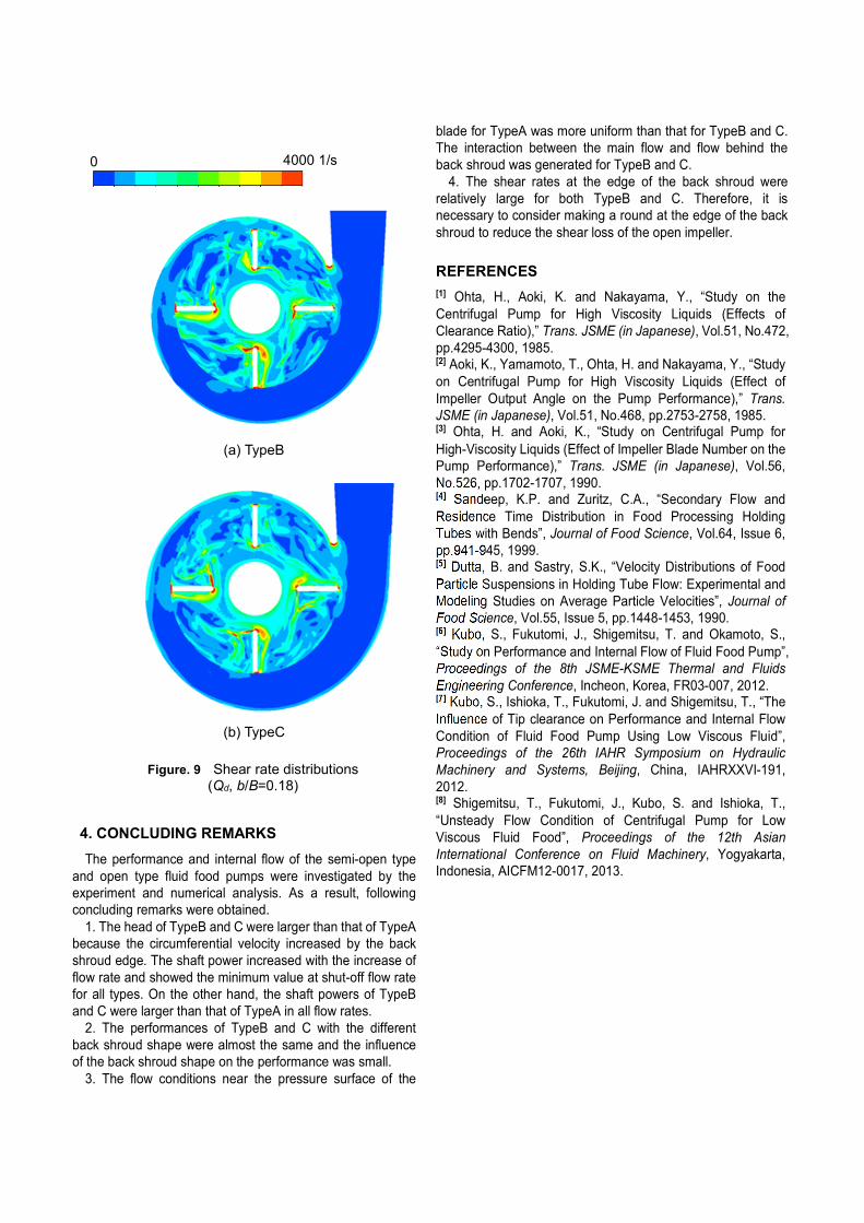
The shear loss is an important factor for the fluid food
pump to evaluate the quality of the fluid food. Then, the shear
rate distributions of the open impeller TypeB and C were
investigated by the numerical analysis results. Figures 9(a)
and (b) show axial cross sectional shear rate distributions in
the impeller near the hub(b/B=0.18). The flow rate, rotation
angle and rotational direction of the impeller were the same
with those of Figs.6. The shear rate was high at the leading
edge, trailing edge of the blade and volute tongue for both
TypeB and C. The shear rates at the edge of the back shroud
were relatively large for both TypeB and C, however, the
tendency of the shear rate distributions between TypeB and C
was similar. Therefore, it is necessary to consider making a
round at the edge of the back shroud to reduce the shear loss
of the open impeller.
Figure. 8 Relative velocity vectors on cylindrical plane (Qd, r=45mm)
(a) TypeA
(b) TypeB
(c) TypeC
Figure. 7 Definition of b and B
(a) TypeA
8.0 m/s
0.0 m/s
Figure. 6 Relative velocity vectors and contours (Qd, b/B=0.18)
(b) TypeB
(c) TypeC
4.0 m/s 0.0
4. CONCLUDING REMARKS
The performance and internal flow of the semi-open type
and open type fluid food pumps were investigated by the
experiment and numerical analysis. As a result, following
concluding remarks were obtained.
1. The head of TypeB and C were larger than that of TypeA
because the circumferential velocity increased by the back
shroud edge. The shaft power increased with the increase of
flow rate and showed the minimum value at shut-off flow rate
for all types. On the other hand, the shaft powers of TypeB
and C were larger than that of TypeA in all flow rates.
2. The performances of TypeB and C with the different
back shroud shape were almost the same and the influence
of the back shroud shape on the performance was small.
3. The flow conditions near the pressure surface of the
blade for TypeA was more uniform than that for TypeB and C.
The interaction between the main flow and flow behind the
back shroud was generated for TypeB and C.
4. The shear rates at the edge of the back shroud were
relatively large for both TypeB and C. Therefore, it is
necessary to consider making a round at the edge of the back
shroud to reduce the shear loss of the open impeller.
REFERENCES
[1] Ohta, H., Aoki, K. and Nakayama, Y., “Study on the
Centrifugal Pump for High Viscosity Liquids (Effects of
Clearance Ratio),” Trans. JSME (in Japanese), Vol.51, No.472,
pp.4295-4300, 1985. [2] Aoki, K., Yamamoto, T., Ohta, H. and Nakayama, Y., “Study
on Centrifugal Pump for High Viscosity Liquids (Effect of
Impeller Output Angle on the Pump Performance),” Trans.
JSME (in Japanese), Vol.51, No.468, pp.2753-2758, 1985. [3] Ohta, H. and Aoki, K., “Study on Centrifugal Pump for
High-Viscosity Liquids (Effect of Impeller Blade Number on the
Pump Performance),” Trans. JSME (in Japanese), Vol.56,
No.526, pp.1702-1707, 1990. [4] Sandeep, K.P. and Zuritz, C.A., “Secondary Flow and
Residence Time Distribution in Food Processing Holding
Tubes with Bends”, Journal of Food Science, Vol.64, Issue 6,
pp.941-945, 1999. [5] Dutta, B. and Sastry, S.K., “Velocity Distributions of Food
Particle Suspensions in Holding Tube Flow: Experimental and
Modeling Studies on Average Particle Velocities”, Journal of
Food Science, Vol.55, Issue 5, pp.1448-1453, 1990. [6] Kubo, S., Fukutomi, J., Shigemitsu, T. and Okamoto, S.,
“Study on Performance and Internal Flow of Fluid Food Pump”,
Proceedings of the 8th JSME-KSME Thermal and Fluids
Engineering Conference, Incheon, Korea, FR03-007, 2012. [7] Kubo, S., Ishioka, T., Fukutomi, J. and Shigemitsu, T., “The
Influence of Tip clearance on Performance and Internal Flow
Condition of Fluid Food Pump Using Low Viscous Fluid”,
Proceedings of the 26th IAHR Symposium on Hydraulic
Machinery and Systems, Beijing, China, IAHRXXVI-191,
2012. [8] Shigemitsu, T., Fukutomi, J., Kubo, S. and Ishioka, T.,
“Unsteady Flow Condition of Centrifugal Pump for Low
Viscous Fluid Food”, Proceedings of the 12th Asian
International Conference on Fluid Machinery, Yogyakarta,
Indonesia, AICFM12-0017, 2013.
(b) TypeC
Figure. 9 Shear rate distributions (Qd, b/B=0.18)
4000 1/s 0
(a) TypeB