Embed Size (px)
Citation preview
3”WPS® Constant Pressure PumpingSystem
Installation and OperationInstructions
WP/
JVG
/1.3
/01.
03.0
9
GB
WP/JVG/1.3/01.03.09
2
GB
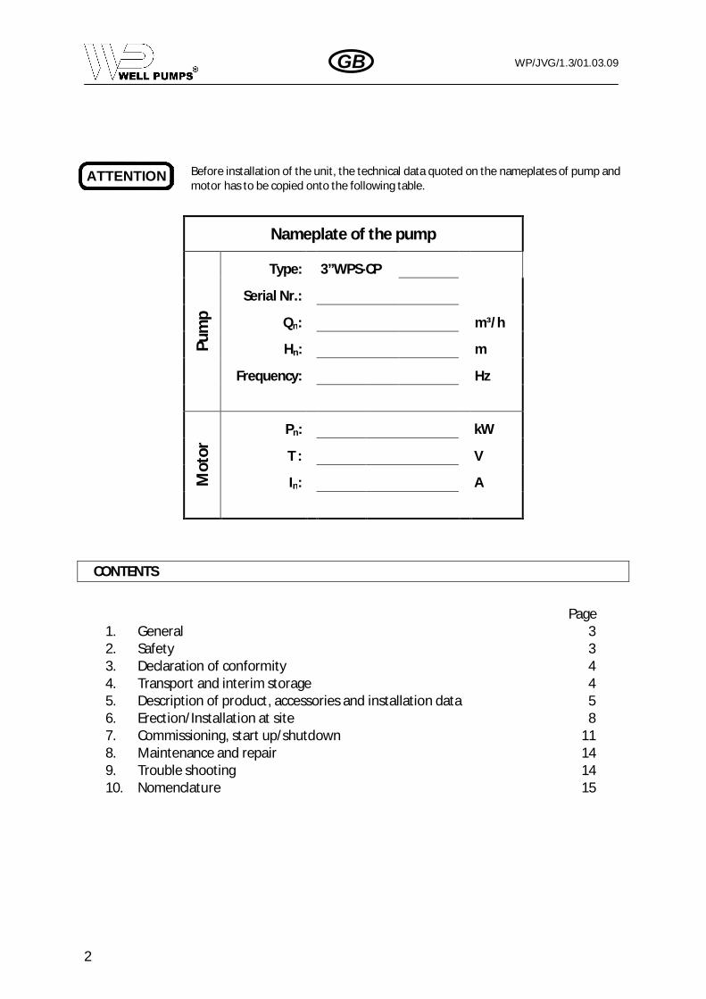
ATTENTION Before installation of the unit, the technical data quoted on the nameplates of pump andmotor has to be copied onto the following table.
CONTENTS
Page1. General 32. Safety 33. Declaration of conformity 44. Transport and interim storage 45. Description of product, accessories and installation data 56. Erection/Installation at site 87. Commissioning, start up/shutdown 118. Maintenance and repair 149. Trouble shooting 1410. Nomenclature 15
Nameplate of the pump
Pum
p
Type: 3”WPS-CP
Serial Nr.:
Qn: m³/h
Hn: m
Frequency: Hz
Mot
or
Pn: kW
T : V
In: A

WP/JVG/1.3/01.03.09
3
GB
ATTENTION
1. GENERAL
1.1. Applications
Submersible motor pumps are designed to pump clean or slightly contaminated water in general water supplysystems, irrigation and sprinkling systems, in ground water lowering and in heat pump installations. Otherapplications include pressure raising, air conditioning, fountains, … Especially suitable for installation in narrowdeep wells.
1.2. Product details
The unit series and size, the most important operating data and the serial number are marked on nameplateson both pump and motor. We recommend that, before installation of the unit, the technical data quoted onthe nameplates are copied onto the second page of this operating instructions.
1.3. Sound pressure level
The sound pressure level of 3”WPS-CP pumps is lower than 70 dB(A)
2. SAFETY
This operating instruction gives basic instructions, which are to be observed during installation, operation andmaintenance. It is therefore imperative that these operating instructions be read and understood by both theservice fitter and the responsible personnel / operator prior to erection and commissioning, and it shall at alltimes be available on the site of the machine.
2.1. Marking of safety instructions in the operating instructions.
Safety instructions given in these operating instructions whose non-observance may cause a hazard to persons,are specifically marked by the following symbols:
In case of general warning(acc. To ISO 3864-B.3.1)
In case of warning of electrical voltage(acc. To ISO 3864-B.3.6)
For safety instructions whose non-observance may cause a dangerto the machine and its function
Non-compliance with safety instructions can jeopardise the safety of personnel, the environment and themachine itself. Non-compliance with these safety instructions will also lead to forfeiture of any and all rights toclaims for damages.In particular, non-compliance can, for example, result in:
Failure of important machine/unit functions,Failure of prescribed maintenance and servicing practices,Hazard to persons by electrical, mechanical and chemical affects.
For installation of the power supply, we recommend to use a high sensitivity residual current device with=30mA (class A or AS)
To improve immunity to the possible noise radiated on other equipments, we recommend to power the controlpanels with a separate wire. In some cases an extra noise filter must be mounted.
WP/JVG/1.3/01.03.09
4
GB
ATTENTION
2.2. Personnel qualification and training
The personnel employed in operating, maintaining, inspecting and erecting the machine must beadequately qualified for this job. Responsibility, authority and supervision of the personnel mustbe exactly defined by the user. In the event of the personnel lacking the necessary knowledge,they should be trained and instructed. Moreover, the user should ensure that the intent of theoperating instructions is fully understood by the personnel.
2.3. Safety instructions for maintenance, inspection and installation work
The user shall see that the above-mentioned work is performed by authorized and qualified specialists thathave adequately acquainted themselves with the matter by thoroughly studying these operating instructions.As a general principle, work on the machine should be carried out only when the machine is at rest. It isimperative that the procedure for shutting down the machine as described in these operating instructions befollowed.
Upon completion of the work, all safety and protection devices shall be re-installed and made operative again.Prior to re-commissioning, note the points mentioned in item «Commissioning».
2.4. Unauthorised modifications and manufacture of spare parts
Conversion work and alteration to the machine is permitted only upon consultation with the manufacturer.Using spare parts and accessories authorized by the manufacturer is in the interest of safety. Use of other partsexempts the manufacturer from any liability.
3. DECLARATION OF CONFORMITY
The company Well Pumps S.A. under its own exclusive responsibility declares that the products 3”WPS®-CPcomply with:Directive on Electromagnetic Compatibility and subsequent modificationCEs 2004/108 .Directive on Low Voltage and subsequent modifications 2006/95 CE.RoHS Directives 2002/95/CEWEEE directives 2002/96/CEMachinery Directives 2006/42 CEConformity to the following CE regulations :CE EN 292, CE EN 55014-1 (2001/11), CEI EN 55014-2 (1998/10), CE EN 61000-3-2 (2002/04), CEI EN 61000-3-3(1997/06), CE EN 60335-1 (2004/04), CE EN 60335-1 (2004/04)
4. TRANSPORT AND INTERIM STORAGE
It is also pointed out in particular for horizontal transport (e.g. with a fork-lift), that the weightdistribution of the pump and motor unit is very uneven. The heaviest point is usually in the areaof the motor. If units are stored or placed vertically, secure properly against falling over.
When opening the package and when handling the unit, always ensure that the electricalconnection cables are not damaged! In particular the electrical cables should never bepulled!.
Any transport and handling of the unit must be carried out correctly. The motor pump 3”WPS®-CP is supplied inpackaging, which prevents flexing or other damage during transport and shelf storage. Prior to and duringunpacking, please check that the packaging is not damaged or moist.
When the unit is temporarily stored it must be stored so that any flexing is avoided. The pump, motor andcontroller may be stored and transported without risk at temperatures down to –30°C.
WP/JVG/1.3/01.03.09
5
GB
5. DESCRIPTION OF PRODUCT, ACCESSORIES AND INSTALLATION DATA
5.1. Introduction
The 3”WPS®-CP pumping system is a residential water supply system that uses advanced electronics based oninverter-based technology, to enhance the performance of the pump. The controller is installed downstream ofthe pump and regulates a constant pressure by means of speed regulation of the motor, resulting in notableenergy savings over time. Moreover, depending on the conditions and usage needs of the hydraulic system, thepump is turned on or off and malfunction conditions are managed.
In addition, the reduced tank size (8 litre) allows installation in small spaces.Key features:
Constant water pressure with a wide range of settings (1,5 up to 7 bar)Considerable energy saving that can exceed 40% in comparison with a common on/of system.Small pressure tank can be used (8 litre)Gradual pump start and stop reduces hammering, no in-rush currentDigital pressure displayRemote connection for remote control or double set-pointExtractable terminals to facilitate wiringProtection features:
Dry well conditions, with automatic resetOver currentOpen motor circuit, short circuitInternal overheating of the controllerLow line voltage (activation at approximately 200Volt)High line voltage (activation at approximately 260Volt)Phase failure
5.2. Designation (Example)
3”WPS®-CP 3 - 80Nominal pressure in mNominal flow in m³/hStainless steel constant pressure submersible pump
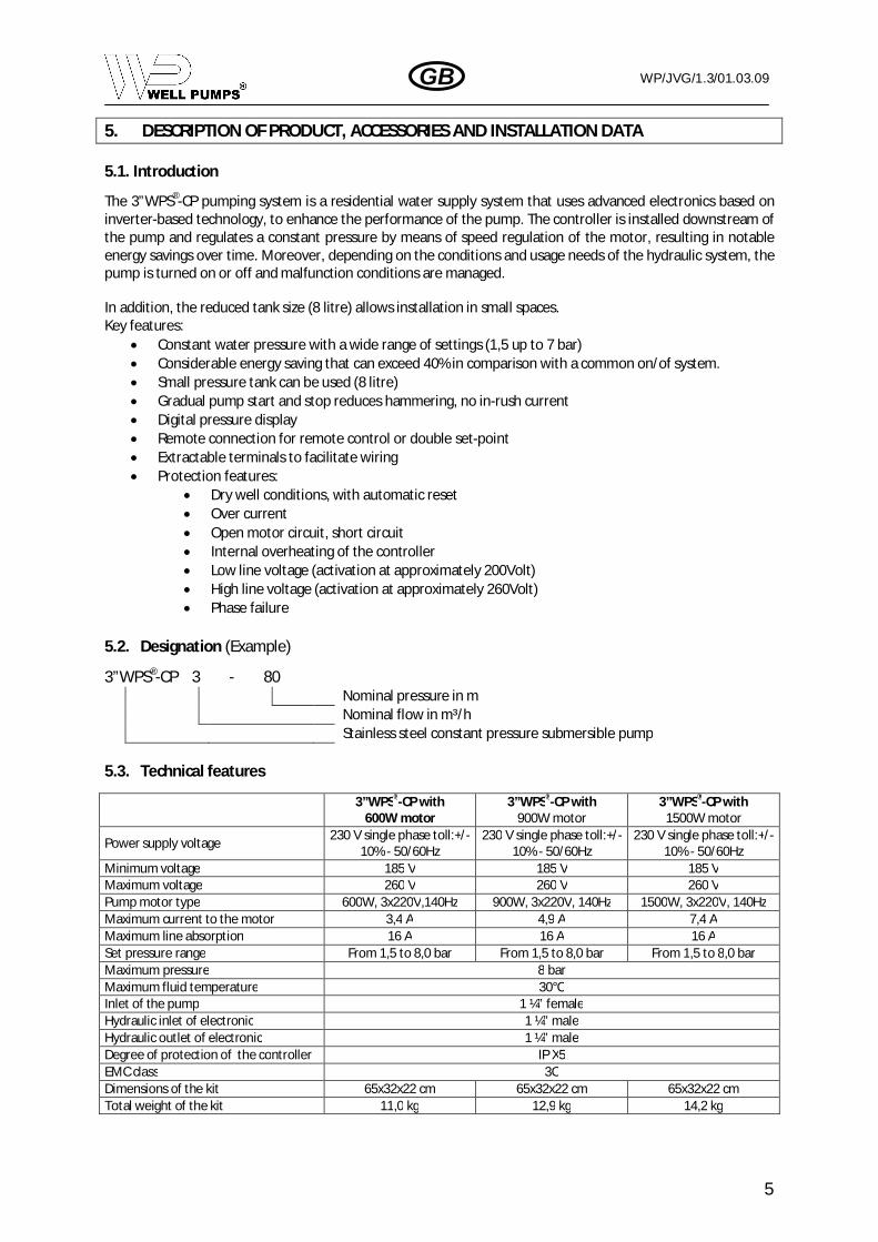
5.3. Technical features
3”WPS®-CP with600W motor
3”WPS®-CP with900W motor
3”WPS®-CP with1500W motor
Power supply voltage230 V single phase toll:+/-
10% - 50/60Hz230 V single phase toll:+/-
10% - 50/60Hz230 V single phase toll:+/-
10% - 50/60HzMinimum voltage 185 V 185 V 185 VMaximum voltage 260 V 260 V 260 VPump motor type 600W, 3x220V,140Hz 900W, 3x220V, 140Hz 1500W, 3x220V, 140HzMaximum current to the motor 3,4 A 4,9 A 7,4 AMaximum line absorption 16 A 16 A 16 ASet pressure range From 1,5 to 8,0 bar From 1,5 to 8,0 bar From 1,5 to 8,0 barMaximum pressure 8 barMaximum fluid temperature 30°CInlet of the pump 1 ¼” femaleHydraulic inlet of electronic 1 ¼” maleHydraulic outlet of electronic 1 ¼” maleDegree of protection of the controller IP X5EMC class 3CDimensions of the kit 65x32x22 cm 65x32x22 cm 65x32x22 cmTotal weight of the kit 11,0 kg 12,9 kg 14,2 kg

WP/JVG/1.3/01.03.09
6
GB
3
21
4
ATTENTION
ATTENTION
5.4. Installation data
5.4.1. Location details
The 3”WPS®-CP motor pump is ideal for vertical installation in smalldimension deep wells or basins, vessels and shafts. Because it ismaintenance-free and should only be operated when fullysubmersed, it does not require any special adaptation of buildings orrooms.
The maximum installation depth is 150 m, with respect to thestationary water level Hh and the lower edge of the motor. Thewater level in the well is usually determined with an electrical plumbline.
1. submersible unit D. I.D. of well2. riser pipe T. depth of well3. support clamp He. Installation depth4. electric cable Hh. Stationary water level
Ht. Operating water level
Note: He – Ht 0,5m!fig. 1: Vertical installation (e.g.: deep well)
This also applies to horizontal installation, mounted in cooling sleeve with supports, which we can also supply.Because pump and motor are delivered as a unit ready for installation, it is not necessary to align pump andmotor at installation location. The foundation soil must be plane and must have a sufficient bearing capacity.
1. Submersible unit with cooling sleeveand supports
2. expansion joint3. spring loaded non return valve4. shut-off valve5. drop cable
Figure 2: Horizontal installation (e.g.: tank or pit)
When the 3”WPS®-CP pump is installed in a horizontal position, an extra spring loaded checkvalve must be mounted (see fig 2). In fact controller starts and stops the pump in a ‘soft mode’.This way the internal check valve of the pump will not always close properly.
The 3”WPS®-CP system works at constant pressure. This regulation is appreciable if thehydraulic system downwards from the controller is correctly installed. Systems made withtoo narrow pipes cause pressure losses which the appliance cannot compensate; the result
is that the pressure is constant on the 3”WPS®-CP controller but not on the user.
It is important to ensure that the unit is installed such that it doesn’t sit on the base of thewell and that the sanding and sludging cannot occur in the vicinity of the submersible
motor. This would disrupt heat dissipation from the motor, possibly dangerously!
4
3
2
1
Ht
Hh
He
T
D

WP/JVG/1.3/01.03.09
7
GB
ATTENTION
5.4.2. Hydraulic connections
The following picture shows the scheme of the correct hydraulic connection.
The hydraulic connection between the pump and the controller must not have any derivationand the pressure vessel should be installed after the controller.
Ice/frost danger: Pay attention to the environment conditions where the controller will be installed and to thehydraulic connections in the cold months. Two types of usage precautions should be observed in case theenvironment temperature drops below 0 °C.
if the unit is working, it is absolutely necessary to protect it adequately from the cold and to keep itconstantly fed.If the unit is not working the controller should be disconnected both from the power supply and fromthe pipes and any water inside should be removed. To ease this procedure a quick release coupling isadvisable. Please note that removing pressure from the pipeline is not enough, since after doing thatsome water still remains in the controller.
Foreign bodies in the pipeline: the presence of dirt inside the fluid can obstruct the duct or stop the flow valve,thus jeopardizing correct operation of the system. In case that the controller is installed on a pipeline throughwhich foreign bodies (e.g. gravel, sand, …) can transit, it is necessary to install a special filter between the pumpand the controller. A coarse porosity one (100 m) will be suitable as well.
5.4.3. Water characteristics
The pump WPS is designed for use with water with the following characteristics:
Temperature: up to + 35°C (for higher temperatures, please contact the producer),Aggressiveness: normal and slightly above.
5.4.4. Pump fluid requirements.
Submersible well pumps are designed for pumping clear, cold water; free of air or gasses.Decreased pump performance and life expectancy can occur if the water is not cold, clearor contains air or gasses.
1 ¼” F
1 ¼” M
1 ¼” M

WP/JVG/1.3/01.03.09
8
GB
ATTENTION
ATTENTION
ATTENTION
Ensure that the requirement for minimum flow of 8 cm/s past the motor is met. Also see the table below.
Minimum flow required for motor cooling in water up to 30°C.Casing or sleeve I.D. 3” motor, cooling flow
8 cm/sec[mm (inches)] [m³/h]
78 (3”) 0,2102 (4”) 1,1127 (5”) 2,4152 (6”) 4,0
In case a minimum flow of 8 cm/s past the motor is not feasible, a range of cooling shrouds are available toensure the correct cooling. Please contact Well Pumps S.A. for more information.
6. ERECTION / INSTALLATION AT SITE
During all installation procedures any open wells/vessels/basins/shafts must be secured toprevent falls!
6.1. Installation tools and Accessories
Proper installation of the 3”WPS®-CP pump requires lifting gear (e.g. a derrick). The capacity of the gear mustbe greater than the weight of the pump unit plus pump riser pipes filled with water and the cable.
6.2. Extending the electrical cable to the pump
Use of the cable connector delivered by us in swimming pools and garden ponds and their vicinityis only admissible if they are built in acc. with the current rule IEC 64 (CO) 124.
If necessary the short electrical cable lead can be extended using a waterproof cable connector, which we cansupply on request. The connection must be executed in accordance with the instructions of the cableconnector. When the extension cable is fitted special care must be taken to ensure that conductor colours areproperly matched. Live-phase conductors are black (U), brown (V) and blue (W). The earth conductor is Green /Yellow.
The electrician is solely responsible for choosing and dimensioning the cable. The minimumcross-section is specified in table below.
Maximum cable length for specific cable section:
Motor size 1,5 mm² 2,5 mm² 4 mm² 6 mm²600 W 100 m 150 m* - -900 W 70 m 115 m 175 m* -
1500 W 45 m 75 m 120 m 170 m**extra filter required
In case the total length of the electrical power cable between controller and motor exceeds120m, an extra filter to protect the motor from burning is required. For more informationplease contact Well Pumps S.A.
6.3. Protection against electric shock
Concerning the protection against electric shock (earthen) it must be observed the national rulesif using any machines with live electric power.
The submersible motor has internal earthen as standard. The earth conductor is connected internally with thestator at the factory. A four conductor short cable with integrated earthen conductor protrudes from themotor. It is the responsibility of the user to ensure that the earthen conductor is properly connected in thecable connector and is extended to the switching unit. IEC stipulates this type of earthen protection foraccessible plant as a compulsory measure.
WP/JVG/1.3/01.03.09
9
GB
ATTENTION
ATTENTION
ATTENTION
6.4. Installation at site
During the entire installation procedure the electrical cable must be protected to preventmechanical damage.
6.5. Fixing the electric cable to the riser pipe
During the installation into the well the electric cable should be fixed step by step to the riser pipe atappreciatively 3 meters intervals by a cable clip, immediately before or after the flanges or couplings of thepipe. The cable clips must be tightened to ensure that the electric cable cannot slip downwards by its ownweight.
6.6. Electrical connection
DANGER! Electrical shock risk.Before carrying out any installation or maintenance operation, the WPS®-CP Controller should bedisconnected from the power supply and one should wait at least 5 minutes before opening theappliance.
During the electric installation all pertinent national stipulations or IEC 64 should be observed.
6.6.1. Connection to the power supply line. (between power supply and controller)
The personnel installing the system must be adequately qualified for this job.
The WPS®-CP Controller must be connected with a power cord to connect the deviceto a 230V 50/60Hz single phase power supply.
Connection to the power line must include a ground line. The total grounding resistance mustnot exceed 150 mOhm.The WPS-CP Controller already provides internal over current protection. If a thermal magneticcircuit breaker is installed, its current must be of 16A.
In case you want a longer electrical cable, you must check the cable section following the table below. Maximalcable length for specific cable sections:
Motor Power 1,5 mm² 2.5 mm² 4 mm² 6 mm²600 W 80 m 130 m 220 m 320 m900W 50 m 90 m 140 m 220 m
1500W 30 m 45 m 80 m 130 m
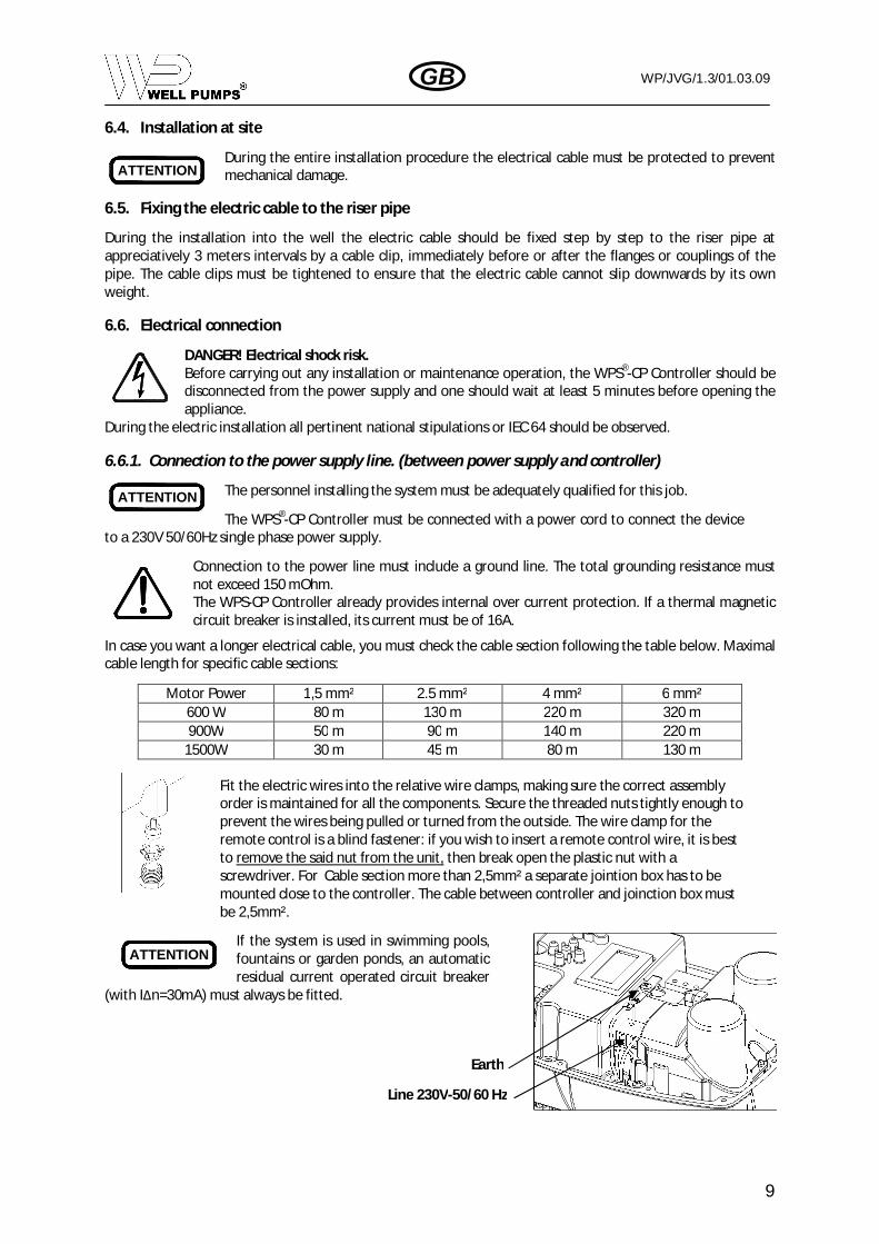
Fit the electric wires into the relative wire clamps, making sure the correct assemblyorder is maintained for all the components. Secure the threaded nuts tightly enough toprevent the wires being pulled or turned from the outside. The wire clamp for theremote control is a blind fastener: if you wish to insert a remote control wire, it is bestto remove the said nut from the unit, then break open the plastic nut with ascrewdriver. For Cable section more than 2,5mm² a separate jointion box has to bemounted close to the controller. The cable between controller and joinction box mustbe 2,5mm².
If the system is used in swimming pools,fountains or garden ponds, an automaticresidual current operated circuit breaker
(with I n=30mA) must always be fitted.
Line 230V-50/60 Hz
Earth
WP/JVG/1.3/01.03.09
10
GB
ATTENTION
To make the electrical connection, remove the green bipolar terminal marked “LINE” and connect the device’stwo power wires, then fit the terminal back onto its seat and proceed by attaching the earth wire to one end ofthe earth faston. The faston terminals must be crimped by specially trained personnel, using proper crimpingpliers.
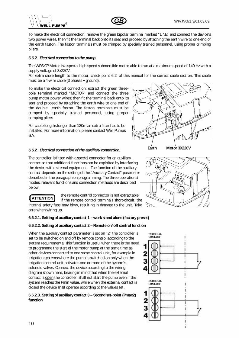
6.6.2. Electrical connection to the pump.
The WPS-CP Motor is a special high speed submersible motor able to run at a maximum speed of 140 Hz with asupply voltage of 3x220V.For extra cable length to the motor, check point 6.2. of this manual for the correct cable section. This cablemust be a 4-wire cable (3 phases + ground).
To make the electrical connection, extract the green three-pole terminal marked “MOTOR” and connect the threepump motor power wires; then fit the terminal back onto itsseat and proceed by attaching the earth wire to one end ofthe double earth faston. The faston terminals must becrimped by specially trained personnel, using propercrimping pliers.
For cable lengths longer than 120m an extra filter has to beinstalled. For more information, please contact Well PumpsS.A.
6.6.2. Electrical connection of the auxiliary connection.
The controller is fitted with a special connector for an auxiliarycontact so that additional functions can be exploited by interfacingthe device with external equipment. The function of the auxiliarycontact depends on the setting of the “Auxiliary Contact” parameterdescribed in the paragraph on programming. The three operationalmodes, relevant functions and connection methods are describedbelow.
the remote control connector is not extractable!if the remote control terminals short-circuit, the
internal safety fuse may blow, resulting in damage to the unit. Takecare when wiring up.
6.6.2.1. Setting of auxiliary contact 1 – work stand alone (factory preset)
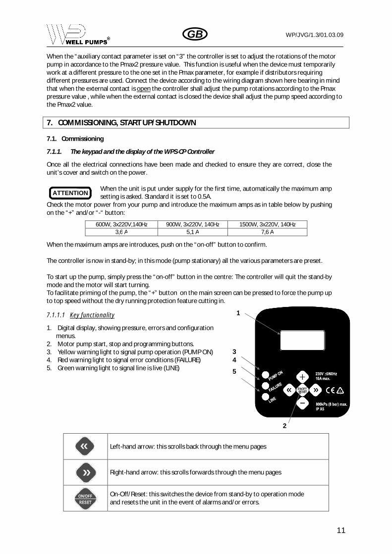
6.6.2.2. Setting of auxiliary contact 2 – Remote on/off control function
When the auxiliary contact parameter is set on “2” the controller isset to be switched on and off by remote control according to thesystem requirements. This function is useful when there is the needto programme the start of the motor pump at the same time asother devices connected to one same control unit, for example inirrigation systems where the pump is switched on only when theirrigation control unit activates one or more of the system’ssolenoid valves. Connect the device according to the wiringdiagram shown here, bearing in mind that when the externalcontact is open the controller shall not start the pump even if thesystem reaches the Pmin value, while when the external contact isclosed the device shall operate according to the values set.
6.6.2.3. Setting of auxiliary contact 3 – Second set-point (Pmax2)function
Earth Motor 3X220V
EXTERNALCONTACT
EXTERNALCONTACT
WP/JVG/1.3/01.03.09
11
GB
ATTENTION
When the “auxiliary contact parameter is set on “3” the controller is set to adjust the rotations of the motorpump in accordance to the Pmax2 pressure value. This function is useful when the device must temporarilywork at a different pressure to the one set in the Pmax parameter, for example if distributors requiringdifferent pressures are used. Connect the device according to the wiring diagram shown here bearing in mindthat when the external contact is open the controller shall adjust the pump rotations according to the Pmaxpressure value , while when the external contact is closed the device shall adjust the pump speed according tothe Pmax2 value.
7. COMMISSIONING, START UP/SHUTDOWN
7.1. Commissioning
7.1.1. The keypad and the display of the WPS-CP Controller
Once all the electrical connections have been made and checked to ensure they are correct, close theunit’s cover and switch on the power.
When the unit is put under supply for the first time, automatically the maximum ampsetting is asked. Standard it is set to 0.5A.
Check the motor power from your pump and introduce the maximum amps as in table below by pushingon the “+” and/or “-“ button:
When the maximum amps are introduces, push on the “on-off” button to confirm.
The controller is now in stand-by; in this mode (pump stationary) all the various parameters are preset.
To start up the pump, simply press the “on-off” button in the centre: The controller will quit the stand-bymode and the motor will start turning.To facilitate priming of the pump, the “+” button on the main screen can be pressed to force the pump upto top speed without the dry running protection feature cutting in.
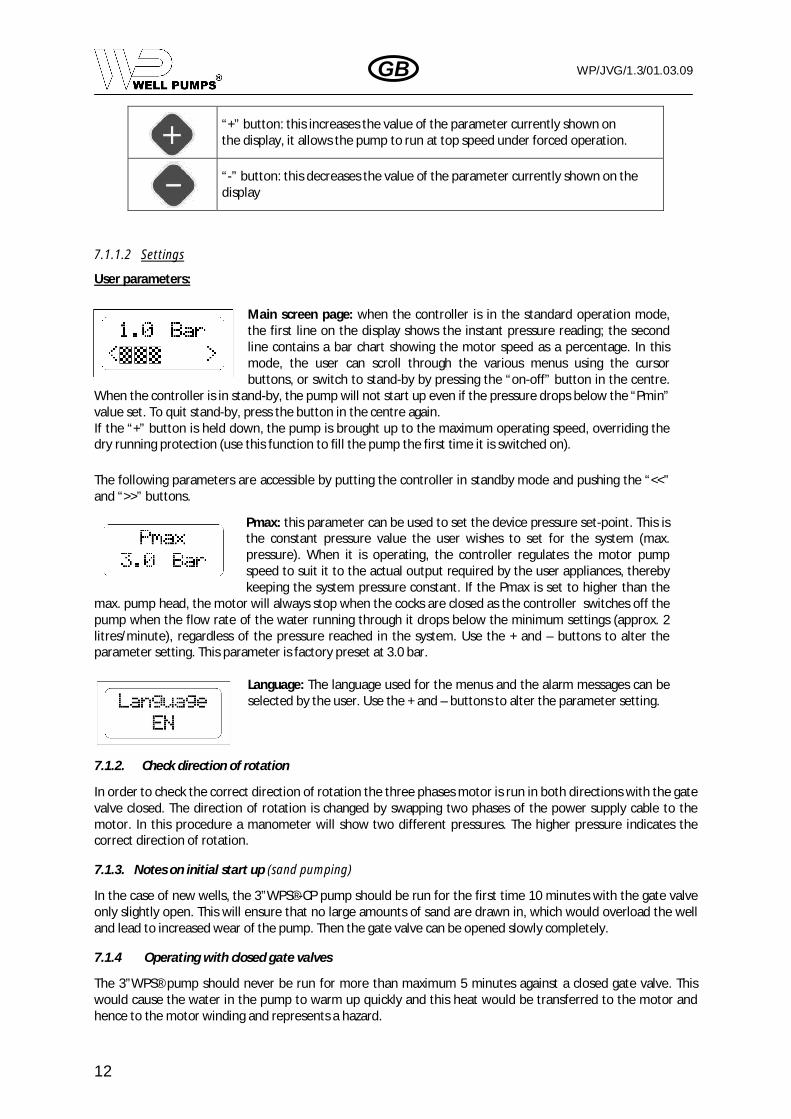
7.1.1.1 Key functionality
1. Digital display, showing pressure, errors and configurationmenus.
2. Motor pump start, stop and programming buttons.3. Yellow warning light to signal pump operation (PUMP ON)4. Red warning light to signal error conditions (FAILURE)5. Green warning light to signal line is live (LINE)
Left-hand arrow: this scrolls back through the menu pages
Right-hand arrow: this scrolls forwards through the menu pages
On-Off/Reset: this switches the device from stand-by to operation modeand resets the unit in the event of alarms and/or errors.
600W, 3x220V,140Hz 900W, 3x220V, 140Hz 1500W, 3x220V, 140Hz3,6 A 5,1 A 7,6 A
1
34
5 2
2
WP/JVG/1.3/01.03.09
12
GB
“+” button: this increases the value of the parameter currently shown onthe display, it allows the pump to run at top speed under forced operation.
“-” button: this decreases the value of the parameter currently shown on thedisplay
7.1.1.2 Settings
User parameters:
Main screen page: when the controller is in the standard operation mode,the first line on the display shows the instant pressure reading; the secondline contains a bar chart showing the motor speed as a percentage. In thismode, the user can scroll through the various menus using the cursorbuttons, or switch to stand-by by pressing the “on-off” button in the centre.
When the controller is in stand-by, the pump will not start up even if the pressure drops below the “Pmin”value set. To quit stand-by, press the button in the centre again.If the “+” button is held down, the pump is brought up to the maximum operating speed, overriding thedry running protection (use this function to fill the pump the first time it is switched on).
The following parameters are accessible by putting the controller in standby mode and pushing the “<<”and “>>” buttons.
Pmax: this parameter can be used to set the device pressure set-point. This isthe constant pressure value the user wishes to set for the system (max.pressure). When it is operating, the controller regulates the motor pumpspeed to suit it to the actual output required by the user appliances, therebykeeping the system pressure constant. If the Pmax is set to higher than the
max. pump head, the motor will always stop when the cocks are closed as the controller switches off thepump when the flow rate of the water running through it drops below the minimum settings (approx. 2litres/minute), regardless of the pressure reached in the system. Use the + and – buttons to alter theparameter setting. This parameter is factory preset at 3.0 bar.
Language: The language used for the menus and the alarm messages can beselected by the user. Use the + and – buttons to alter the parameter setting.
7.1.2. Check direction of rotation
In order to check the correct direction of rotation the three phases motor is run in both directions with the gatevalve closed. The direction of rotation is changed by swapping two phases of the power supply cable to themotor. In this procedure a manometer will show two different pressures. The higher pressure indicates thecorrect direction of rotation.
7.1.3. Notes on initial start up (sand pumping)
In the case of new wells, the 3”WPS®-CP pump should be run for the first time 10 minutes with the gate valveonly slightly open. This will ensure that no large amounts of sand are drawn in, which would overload the welland lead to increased wear of the pump. Then the gate valve can be opened slowly completely.
7.1.4 Operating with closed gate valves
The 3”WPS® pump should never be run for more than maximum 5 minutes against a closed gate valve. Thiswould cause the water in the pump to warm up quickly and this heat would be transferred to the motor andhence to the motor winding and represents a hazard.
WP/JVG/1.3/01.03.09
13
GB
7.2. Operating limits
Operational safety requirements stipulate that the 3”WPS®-CP pump may only be operated continuouslywithin the pump output and pump head limits specified on the technical documentation.
7.3. Storage and preservation
In principle the pump 3”WPS®-CP should be stored in vertical or horizontal position, dry and protected againstdirect sunlight, heat and dust. If not possible, the unit must be placed to avoid flexing. The unit must besuitably supported to avoid flexing especially at centre coupling position. In this process it must be takenmeasures to ensure that the cable at the outlet of cable guard is protected from folding / bending. It is notnecessary to preserve the unit specially.
7.4. Returning to service after storage
In the case of recommissioning (restarting after longer stand still times or removal) check that the pump dataare still within the values quoted on the name plate.
8. MAINTENANCE AND REPAIR
The 3”WPS®-CP unit is maintenance-free.In order to pinpoint indications of potential damage early, we recommend that the current consumption and ifpossible the pump head are checked at regular intervals. It is not necessary to pull out the pump for regularinspection purposes.
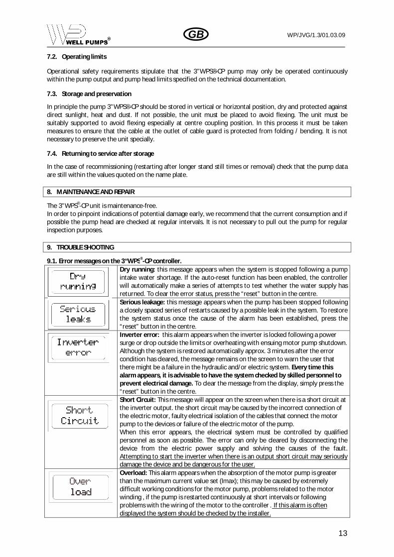
9. TROUBLE SHOOTING
9.1. Error messages on the 3“WPS®-CP controller.Dry running: this message appears when the system is stopped following a pumpintake water shortage. If the auto-reset function has been enabled, the controllerwill automatically make a series of attempts to test whether the water supply hasreturned. To clear the error status, press the “reset” button in the centre.Serious leakage: this message appears when the pump has been stopped followinga closely spaced series of restarts caused by a possible leak in the system. To restorethe system status once the cause of the alarm has been established, press the“reset” button in the centre.Inverter error: this alarm appears when the inverter is locked following a powersurge or drop outside the limits or overheating with ensuing motor pump shutdown.Although the system is restored automatically approx. 3 minutes after the errorcondition has cleared, the message remains on the screen to warn the user thatthere might be a failure in the hydraulic and/or electric system. Every time thisalarm appears, it is advisable to have the system checked by skilled personnel toprevent electrical damage. To clear the message from the display, simply press the“reset” button in the centre.Short Circuit: This message will appear on the screen when there is a short circuit atthe inverter output. the short circuit may be caused by the incorrect connection ofthe electric motor, faulty electrical isolation of the cables that connect the motorpump to the devices or failure of the electric motor of the pump.When this error appears, the electrical system must be controlled by qualifiedpersonnel as soon as possible. The error can only be cleared by disconnecting thedevice from the electric power supply and solving the causes of the fault.Attempting to start the inverter when there is an output short circuit may seriouslydamage the device and be dangerous for the user.Overload: This alarm appears when the absorption of the motor pump is greaterthan the maximum current value set (Imax); this may be caused by extremelydifficult working conditions for the motor pump, problems related to the motorwinding , if the pump is restarted continuously at short intervals or followingproblems with the wiring of the motor to the controller . If this alarm is oftendisplayed the system should be checked by the installer.

WP/JVG/1.3/01.03.09
14
GB
If the problems persist, we suggest to contact Well Pumps S.A.
9.2. The pump fails to deliver or delivers insufficient liquid.Discharge valve is closed. Check the discharge valveReverse rotation Change over two of the phase leads of the power
supply cable to the motorSelection of the wrong pump Pull the pump and install the correct one following the
well characteristicsDefective or clogged raiser pipe Repair the raiser pipeClogged strainer of suction interconnector Clean strainer of pumpClogged pump or check valve Pull the pump and repair itThere are leaks in the installation Check the installation for leaksBroken shaft or coupling Pull the pump and inspect, replace if necessary
9.3. The pump delivers insufficient head.Low water level in the well Pull the pump and install the correct one following the
well characteristics. (never install the pump at thebottom of the well)
Pressure settings Check settings on the pressure and changeReverse rotation Change over two of the phase leads of the power
supply cable to the motorThere are leaks in the installation Check the installation for leaksWorn pump Pull the pump and replace worn partsImpellers are clocked Pull the pump and inspect
9.4. The pump runs rough and noisily.Clogged pump Pull the pump and repair itExcessive amount of air or gas in the liquid pumped Relieve air or gas from the waterDefective motor thrust bearing Change thrust bearingDefective radial bearing in pump Change bearingsVibration caused by the installation Check and change the installation
WP/JVG/1.3/01.03.09
15
GB
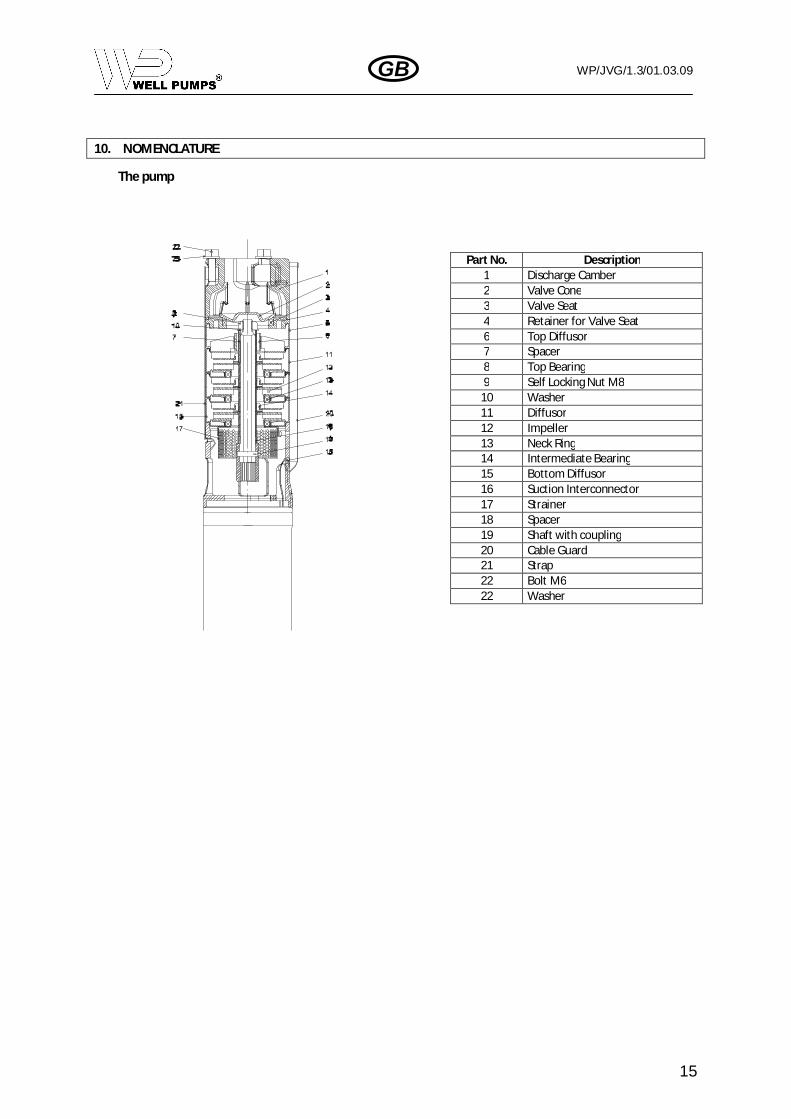
10. NOMENCLATURE
The pump
Part No. Description1 Discharge Camber2 Valve Cone3 Valve Seat4 Retainer for Valve Seat6 Top Diffusor7 Spacer8 Top Bearing9 Self Locking Nut M8
10 Washer11 Diffusor12 Impeller13 Neck Ring14 Intermediate Bearing15 Bottom Diffusor16 Suction Interconnector17 Strainer18 Spacer19 Shaft with coupling20 Cable Guard21 Strap22 Bolt M622 Washer
WP/JVG/1.3/01.03.09
16
GB
WELL PUMPS S.A.Z.I. de Fleurus
Avenue de Lambusart 18B-6220 Fleurus
Belgium
Tel : + 32 71 46.07.83Fax : + 32 71 46.07.71
e-mail : [email protected] : www.wellpumps.be
WELL PUMPS