Embed Size (px)
Citation preview

1
INSTALLATION AND OPERATION MANUAL
RECEIVINGWhen this equipment is shipped, title passes to the pur-chaser upon receipt from the carrier. Consequently, claims for the material damaged in shipment must be made by the purchaser against the transportation company at the time shipment is received.
BE SAFEYour new lift was designed and built with safety in mind. However, your overall safety can be increased by proper training and thoughtful operation on the part of the opera-tor. DO NOT operate or repair this equipment without read-ing this manual and the important safety instructions shown inside. Keep this manual near the machine at all times. Make sure that all users read and understand this manual prior to use. 1645 Lemonwood Dr.
Santa Paula, CA. 93060, USAToll Free 1-800-253-2363
Tel: 1-805-933-9970Fax: 1-805-933-9160
wwwbendpak.com
IMPORTANT SAFETY INSTRUCTIONS SAVE THESE INSTRUCTIONS
Please read the entire contents of this manual prior to installation and operation. By proceeding you agree that you fully understand and comprehend the full con-tents of this manual. Forward this manual to all operators. Failure to operate this equipment as directed may cause injury or death.
MAN REV A 11/17/11P/N 5900175
6,000 POUNd CAPACITYdOUBlE STACkERTIlT PARkING lIFT
MOdElS:PlT-6NPlT-6NxPlT-6SPlT-6SxPlT-6wPlT-6wx
2
6,000 POUNd CAPACITY dOUBlE STACkER TIlT PARkING lIFTS
This instruction manual has been prepared specifically for you. Your new lift is the product of over 40 years of continuing research, testing and development; it is the most technically advanced lift on the market today.
READ THIS ENTIRE MANUAL BEFORE INSTALLATION & OPERATION BEGINS.
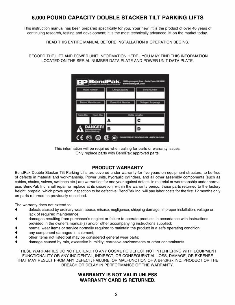
RECORD THE LIFT AND POWER UNIT INFORMATION HERE. YOU MAY FIND THIS INFORMATIONLOCATED ON THE SERIAL NUMBER DATA PLATE AND POWER UNIT DATA PLATE.
This information will be required when calling for parts or warranty issues.Only replace parts with BendPak approved parts.
PROdUCT wARRANTYBendPak Double Stacker Tilt Parking Lifts are covered under warranty for five years on equipment structure, to be free of defects in material and workmanship. Power units, hydraulic cylinders, and all other assembly components (such as cables, chains, valves, switches etc.) are warrantied for one year against defects in material or workmanship under normal use. BendPak Inc. shall repair or replace at its discretion, within the warranty period, those parts returned to the factory freight, prepaid, which prove upon inspection to be defective. BendPak Inc. will pay labor costs for the first 12 months only on parts returned as previously described.
The warranty does not extend to:t defects caused by ordinary wear, abuse, misuse, negligence, shipping damage, improper installation, voltage or lack of required maintenance;t damages resulting from purchaser’s neglect or failure to operate products in accordance with instructions provided in the owner’s manual(s) and/or other accompanying instructions supplied;t normal wear items or service normally required to maintain the product in a safe operating condition;t any component damaged in shipment;t other items not listed but may be considered general wear parts;t damage caused by rain, excessive humidity, corrosive environments or other contaminants.
THESE WARRANTIES DO NOT EXTEND TO ANY COSMETIC DEFECT NOT INTERFERING WITH EQUIPMENT FUNCTIONALITY OR ANY INCIDENTAL, INDIRECT, OR CONSEQUENTIAL LOSS, DAMAGE, OR EXPENSE
THAT MAY RESULT FROM ANY DEFECT, FAILURE, OR MALFUNCTION OF A BendPak INC. PRODUCT OR THE BREACH OR DELAY IN PERFORMANCE OF THE WARRANTY.
wARRANTY IS NOT VAlId UNlESSwARRANTY CARd IS RETURNEd.
3
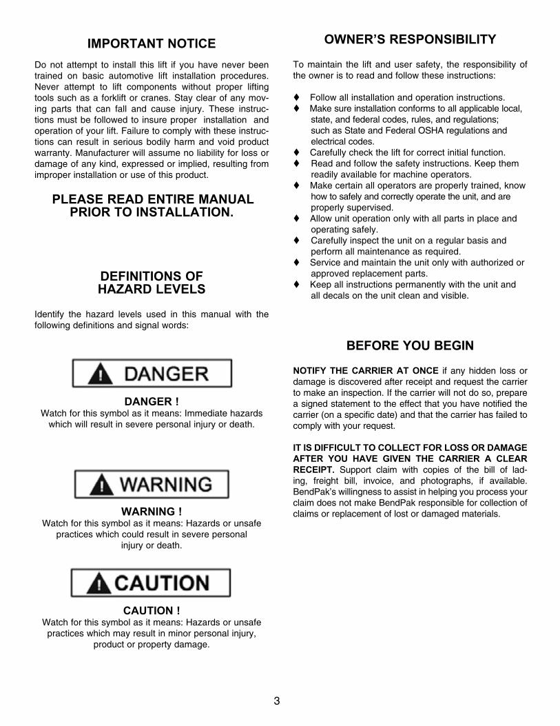
IMPORTANT NOTICEDo not attempt to install this lift if you have never been trained on basic automotive lift installation procedures. Never attempt to lift components without proper lifting tools such as a forklift or cranes. Stay clear of any mov-ing parts that can fall and cause injury. These instruc-tions must be followed to insure proper installation and operation of your lift. Failure to comply with these instruc-tions can result in serious bodily harm and void product warranty. Manufacturer will assume no liability for loss or damage of any kind, expressed or implied, resulting from improper installation or use of this product.
PlEAsE REAd ENTIRE MANuAl PRIOR TO INsTAllATION.
dEfINITIONs Of HAzARd lEvEls
Identify the hazard levels used in this manual with the following definitions and signal words:
dANGER !Watch for this symbol as it means: Immediate hazards
which will result in severe personal injury or death.
WARNING !Watch for this symbol as it means: Hazards or unsafe
practices which could result in severe personal injury or death.
CAuTION !Watch for this symbol as it means: Hazards or unsafe
practices which may result in minor personal injury, product or property damage.
OWNER’s REsPONsIbIlITy
To maintain the lift and user safety, the responsibility of the owner is to read and follow these instructions:
tFollow all installation and operation instructions.tMake sure installation conforms to all applicable local, state, and federal codes, rules, and regulations; such as State and Federal OSHA regulations and electrical codes.tCarefully check the lift for correct initial function.tRead and follow the safety instructions. Keep them readily available for machine operators.tMake certain all operators are properly trained, know how to safely and correctly operate the unit, and are properly supervised.tAllow unit operation only with all parts in place and operating safely.tCarefully inspect the unit on a regular basis and perform all maintenance as required.tService and maintain the unit only with authorized or approved replacement parts.tKeep all instructions permanently with the unit and all decals on the unit clean and visible.
bEfORE yOu bEGIN
NOTIfy THE CARRIER AT ONCE if any hidden loss or damage is discovered after receipt and request the carrier to make an inspection. If the carrier will not do so, prepare a signed statement to the effect that you have notified the carrier (on a specific date) and that the carrier has failed to comply with your request.
IT Is dIffICulT TO COllECT fOR lOss OR dAMAGE AfTER yOu HAvE GIvEN THE CARRIER A ClEAR RECEIPT. Support claim with copies of the bill of lad-ing, freight bill, invoice, and photographs, if available. BendPak’s willingness to assist in helping you process your claim does not make BendPak responsible for collection of claims or replacement of lost or damaged materials.

4
LIFT HEIGHT CLEARNACE NOTE: There must be a 1” MIN distance from the top of the loaded vehicle to the nearest obstruction when the lift is in a raised position.
ClEARANCEsPlT-6 sERIEs
A
B
305MIN
C
D
Model PlT-6N PlT-6NX PlT-6s PlT-6sX PlT-6W PlT-6WXA - Overall length 153.5” / 3899mm 153.2” / 3891mm 153.5” / 3899mm 153.2” / 3891mm 153.5” / 3899mm 153.2” / 3891mmb - Overall Width 92.4” / 2347mm 92.4” / 2347mm 98.3” / 2497mm 98.3” / 2497mm 103.2” / 2622mm 103.2” / 2622mm
C - To NearestObstruction RH
58.2” / 1479mm 58.2” / 1479mm 61.2” / 1554mm 61.2” / 1554mm 63.6” / 1616mm 63.6” / 1616mm
C - To Nearest Obstruction lH
58.2” / 1479mm 58.2” / 1479mm 61.2” / 1554mm 61.2” / 1554mm 63.6” / 1616mm 63.6” / 1616mm

5
TAblE Of CONTENTsContents Page No.
Warranty / Serial Number Information . . . . . . . . . . . . . . . . . . . . . . . . . . . . . . . . . . . . . . . . . . . . . . . . . . . . . . . . . . . . . . . 2
Definitions of Hazard Levels . . . . . . . . . . . . . . . . . . . . . . . . . . . . . . . . . . . . . . . . . . . . . . . . . . . . . . . . . . . . . . . . . . . . . 3
Owner’s Responsibility . . . . . . . . . . . . . . . . . . . . . . . . . . . . . . . . . . . . . . . . . . . . . . . . . . . . . . . . . . . . . . . . . . . . . . . . . 3
Before You Begin . . . . . . . . . . . . . . . . . . . . . . . . . . . . . . . . . . . . . . . . . . . . . . . . . . . . . . . . . . . . . . . . . . . . . . . . . . . . . 3
Clearances . . . . . . . . . . . . . . . . . . . . . . . . . . . . . . . . . . . . . . . . . . . . . . . . . . . . . . . . . . . . . . . . . . . . . . . . . . . . . 4
Installer/Operator Agreement/ Protective Equipment . . . . . . . . . . . . . . . . . . . . . . . . . . . . . . . . . . . . . . . . . . . . . . . . . 6
Introduction . . . . . . . . . . . . . . . . . . . . . . . . . . . . . . . . . . . . . . . . . . . . . . . . . . . . . . . . . . . . . . . . . . . . . . . . . . . . . . . . . . 7
Safety / Warning Instructions . . . . . . . . . . . . . . . . . . . . . . . . . . . . . . . . . . . . . . . . . . . . . . . . . . . . . . . . . . . . . . 7
Tools Required . . . . . . . . . . . . . . . . . . . . . . . . . . . . . . . . . . . . . . . . . . . . . . . . . . . . . . . . . . . . . . . . . . . . . . . . . . . . . . . 8
Step 1 / Selecting Site . . . . . . . . . . . . . . . . . . . . . . . . . . . . . . . . . . . . . . . . . . . . . . . . . . . . . . . . . . . . . . . . . 8
Step 2 / Floor Requirements . . . . . . . . . . . . . . . . . . . . . . . . . . . . . . . . . . . . . . . . . . . . . . . . . . . . . . . . . . . . . . 8
Concrete Specifications . . . . . . . . . . . . . . . . . . . . . . . . . . . . . . . . . . . . . . . . . . . . . . . . . . . . . . . . . . . 8
Assembly View / Description of Parts / Parts Inventory . . . . . . . . . . . . . . . . . . . . . . . . . . . . . . . . . . . . . . . . . . . . 9
Floor Plan / General Specifications . . . . . . . . . . . . . . . . . . . . . . . . . . . . . . . . . . . . . . . . . . . . . . . . . . . 10
Step 3 / Base Frame Assembly . . . . . . . . . . . . . . . . . . . . . . . . . . . . . . . . . . . . . . . . . . . . . . . . . . . . . . . . . . . 11-12
Step 4 / Lift Arm Assembly . . . . . . . . . . . . . . . . . . . . . . . . . . . . . . . . . . . . . . . . . . . . . . . . . . . . . . . . . . . 13
Step 5 / Lift Arm Assembly Installation . . . . . . . . . . . . . . . . . . . . . . . . . . . . . . . . . . . . . . . . . . . . . . . . . . . 14
Step 6 / Ramp Installation Preparation . . . . . . . . . . . . . . . . . . . . . . . . . . . . . . . . . . . . . . . . . . . . . . . . . . . . . . . . 15
Step 7 / Ramp & Safety Bar Installation . . . . . . . . . . . . . . . . . . . . . . . . . . . . . . . . . . . . . . . . . . . . . . . . . 15-17
Step 8 / Tire Stop Bar Installation . . . . . . . . . . . . . . . . . . . . . . . . . . . . . . . . . . . . . . . . . . . . . . . . . . . . . . 17-18
Step 9 / Drive-Up Ramp Installation . . . . . . . . . . . . . . . . . . . . . . . . . . . . . . . . . . . . . . . . . . . . . . . . . . . . . 18
Step 10 / Cylinder Installation . . . . . . . . . . . . . . . . . . . . . . . . . . . . . . . . . . . . . . . . . . . . . . . . . . . . . . . . 19-20
Step 11 / Control Arm Installation . . . . . . . . . . . . . . . . . . . . . . . . . . . . . . . . . . . . . . . . . . . . . . . . . . . . . . . . . 20
Step 12 / Lift Anchoring . . . . . . . . . . . . . . . . . . . . . . . . . . . . . . . . . . . . . . . . . . . . . . . . . . . . . . 20-21
Power Unit Wiring Diagram . . . . . . . . . . . . . . . . . . . . . . . . . . . . . . . . . . . . . . . . . . . . . . . . . . . . . . . . . . . . . 22
Step 13 / Power Unit Electrical Connection . . . . . . . . . . . . . . . . . . . . . . . . . . . . . . . . . . . . . . . . . . . . . . . 23
Step 14 / Hydraulic, Air and Electrical Line Routing . . . . . . . . . . . . . . . . . . . . . . . . . . . . . . . . . . . . . . . . . 23-24
Step 15 / Lift Start-Up . . . . . . . . . . . . . . . . . . . . . . . . . . . . . . . . . . . . . . . . . . . . . . . . . . . . . . . . . . 24
Step 16 / Safety Installation . . . . . . . . . . . . . . . . . . . . . . . . . . . . . . . . . . . . . . . . . . . . . . . . . . 24-26
Step 17 / Bleeding the Cylinder . . . . . . . . . . . . . . . . . . . . . . . . . . . . . . . . . . . . . . . . . . . . . . . . . . . . . . 26
Post Installation Checklist . . . . . . . . . . . . . . . . . . . . . . . . . . . . . . . . . . . . . . . . . . . . . . . . . . . . . . . . . . . . 26
Step 18 / Operation . . . . . . . . . . . . . . . . . . . . . . . . . . . . . . . . . . . . . . . . . . . . . . . . . . . . . . . . . . 26
Safe Lift Operation . . . . . . . . . . . . . . . . . . . . . . . . . . . . . . . . . . . . . . . . . . . . . . . . . . . . . . . . . . . . 27-28
Safety Label Placement / Guidelines . . . . . . . . . . . . . . . . . . . . . . . . . . . . . . . . . . . . . . . . . . . . . . . . . 29-33
Troubleshooting Guide . . . . . . . . . . . . . . . . . . . . . . . . . . . . . . . . . . . . . . . . . . . . . . . . . . . . 34-37
Lubrication Locations / Bolt Torque Specifications . . . . . . . . . . . . . . . . . . . . . . . . . . . . . . . . . . . . . . . . 38
Maintenance . . . . . . . . . . . . . . . . . . . . . . . . . . . . . . . . . . . . . . . . . . . . . . . . . . . . . . . . . . . . . . . . 39
Maintenance Records . . . . . . . . . . . . . . . . . . . . . . . . . . . . . . . . . . . . . . . . . . . . . . . . . . . . . . . . . . . . . . . . 40
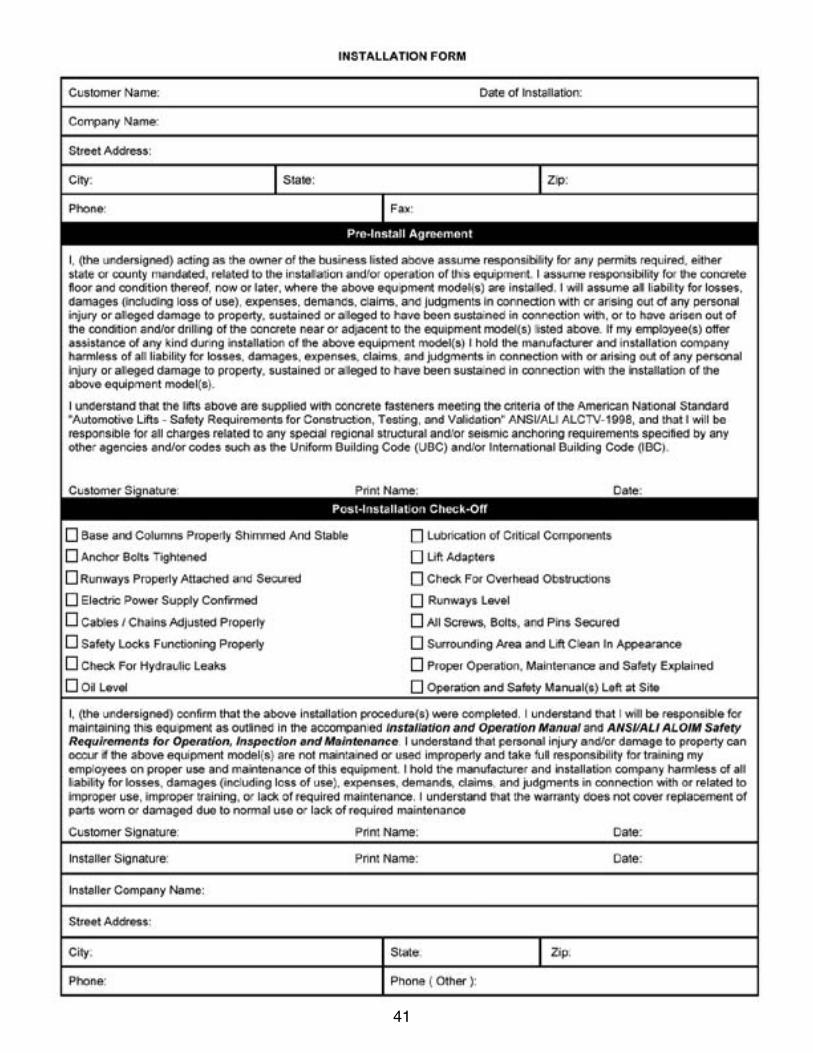
Installation Form . . . . . . . . . . . . . . . . . . . . . . . . . . . . . . . . . . . . . . . . . . . . . . . . . . . . . . . . . . . . . . . . . 41
Part Number Lists . . . . . . . . . . . . . . . . . . . . . . . . . . . . . . . . . . . . . . . . . . . . . . . . . . . . . . . 42-55

6
INsTAllER / OPERATORPlEAsE REAd ANd fully
uNdERsTANd. by PROCEEdING, yOu AGREE TO THE fOllOWING:
tI have visually inspected the site where the lift is to be installed and verified the concrete to be in good condition, free of cracks or other defects. I understand that install-ing a lift on cracked or defective concrete could cause lift failure resulting in personal injury or death.
t I understand that a level floor is required for proper installation and level lifting.
t I understand that I am responsible if my floor is of questionable slope, and that I will be responsible for all charges related to pouring a new level concrete slab if required.
t I understand that BendPak lifts are supplied with concrete fasteners meeting the criteria of the American National Standard “Automotive Lifts - Safety Requirements for Construction, Testing, and Validation” ANSI/ALI ALCTV-2006, and that I will be responsible for all charges related to any special, regional, structural, and/or seismic anchoring requirements specified by any other agencies and/or codes such as the Uniform Building Code (UBC) and/or International Building Code (IBC).
t I will assume full responsibility for the concrete floor and condition thereof, now or later, where the above equipment model is to be installed. Failure to follow Danger, Warning, and Caution instructions may lead to serious personal injury or death to operator or bystander or damage to property.
t I understand that BendPak lifts are designed to be installed in indoor locations only. Failure to follow installa-tion instructions may lead to serious personal injury, death to operator or bystander, or damage to property or lift.
Failure to follow Danger, Warning, and Caution instruc-tions may lead to serious personal injury, death to opera-
tor or bystander or damage to property or lift.
Please read the entire manual prior to installation.Do not operate this machine until you have read and
have understood all of the Danger, Warning and Caution alerts in this manual. For additional copies
or further information, contact:
bendPak Inc.1645 Lemonwood Dr.
Santa Paula, CA. 93060
1-805-933-9970
www.bendpak.com
INsTAllER / OPERATORPROTECTIvE EquIPMENT
Personal protective equipment helps makes installation and operation safer; however, it does not take the place of safe operating practices. Always wear durable work clothing during any installation and/or service activity. Shop aprons or shop coats may also be worn; however, loose-fitting clothing should be avoided.
Tight-fitting leather gloves are recommended to protect the technician’s hands when handling parts. Sturdy leath-er steel-toe work shoes and oil resistant soles should be used by all service personnel to help prevent injury during typical installation and operation activities.
Eye protection is essential during installa-tion and operation activities. Safety glass-es with side shields, goggles, or face shields are acceptable. Back belts provide support during lifting activities and are also helpful in providing worker protection. Consideration should also be given to the use of hearing protection if service activity is performed in an enclosed area or if noise levels are high.
THIs syMbOl POINTs OuT IMPORTANT sAfETy INsTRuCTIONs WHICH If NOT fOllOWEdCOuld ENdANGER THE PERsONAl sAfETy ANd/OR PROPERTy OR yOuRsElf ANd OTHERsANd CAN CAusE PERsONAl INJuRy OR dEATH. REAd ANd fOllOW All INsTRuCTIONs IN
THIs MANuAl bEfORE ATTEMPTING TO OPERATE THIs MACHINE.

7
1. Carefully remove the crating and packing materials. CAUTION! Be careful when cutting steel banding material as items may become loose and fall, causing personal harm or injury.
2. Check the voltage, phase, and proper amperage requirements for the motor shown on the motor plate. Electrical work should be performed only by a certified electrician.
IMPORTANT SAFETY INSTRUCTIONSRead these safety instructions entirely. Do not attempt to install this lift if you have never been trained
on basic automotive lift installation procedures. Never attempt to lift components without proper lifting tools such as forklift or cranes. Stay clear of any moving parts that may fall and cause injury. When using your garage equipment,
basic safety precautions should always be followed, including the following:
INTROdUCTION
1. Read and understand all instructions and all safety warn-ings before operating lift.2. Care must be taken as burns can occur from touching hot parts.3. Do not operate equipment with a damaged cord or if the equipment has been dropped or damaged until it has been examined by a qualified service person.4. Do not let a cord come in contact with hot manifolds or moving fan blades.5. If an extension cord is necessary, a cord with a current rating equal to or more than that of the equipment should be used. Cords rated for less current than the equipment may overheat. Care should be taken to arrange the cord so that it will not be tripped over or pulled.6. Always unplug equipment from electrical outlet when not in use. Never use the cord to pull the plug from the outlet. Grasp plug and pull to disconnect.7. Let equipment cool completely before putting away. Loop cord loosely around equipment when storing.8. To reduce the risk of fire, do not operate equipment in the vicinity of open containers of flammable liquids (gasoline).9. Adequate ventilation should be provided when working on operating internal combustion engines.10. Keep hair, loose clothing, fingers, and all parts of body away from moving parts. Keep feet clear of lift when lowering. Avoid pinch points.11. DANGER! To reduce the risk of elec-tric shock, do not use on wet surfaces or expose to rain. The power unit used on this lift contains high voltage. Disconnect power at the receptacle or at the circuit breaker switch before performing any elec-trical repairs. Secure plug so that it cannot be accidentally plugged in during service, or mark circuit breaker switch so that it cannot be accidentally switched on during service.12. Tighten all fasteners to meet recommended torque specifications found on page 33 of this manual.
13. Use only as described in this manual. Use only manu-facturer’s recommended attachments.14. AlwAYS WEAR SAFETY GLASSES. Everyday eye-glasses only have impact resistant lenses, they are not safety glasses.15. Consider work environment. Keep work area clean. Cluttered work areas invite injuries. Keep areas well lit.16. Guard against electric shock. This lift must be grounded while in use to protect operator from electric shock. Never connect the green power cord wire to a live terminal. This is for ground only.17. Only trained operators should operate this lift. All non-trained personnel should be kept away from the work area. Never let non-trained personnel come in contact with, or operate lift.18. DO NOT override self-closing lift controls.19. Clear area if vehicle is in danger of falling.20. AlwAYS make sure the safeties are engaged before attempting to work on or near a vehicle.21. WARNING! RISK OF EXPLOSION. This equipment has internal arcing or sparking parts which should not be exposed to flam-mable vapors. This machine should not be located in a recessed area or below floor level.22. MAINTAIN WITH CARE. Keep lift clean for better and safer performance. Follow manual for proper lubrication and maintenance instructions. Keep control handles and/or but-tons dry, clean and free from grease and oil.23. Check for damaged parts. Check for alignment of mov-ing parts, breakage of parts or any condition that may affect operation of lift. Do not use lift if any component is broken or damaged.24. NEVER remove safety related components from the lift. Do not use lift if safety related components are missing or damaged.25. STAY ALERT. Use common sense and watch what you are doing. Remember, SAFETY FIRST.
SAVE THESE INSTRUCTIONS

8
STEP 1(selecting site)
Before installing your new lift, check the following:
1. LIFT LOCATION: Always use architectural plans when available. Check the layout dimension against the floor plan requirements, making sure that adequate space if available.
2. OVERHEAD OBSTRUCTIONS: The area where the lift will be located should be free of overhead obstructions such as heaters, building supports, electrical lines, etc.
3. DEFECTIVE FLOOR: Visually inspect the site where the lift is to be installed and check for cracked or defective concrete.
4. Your new BendPak Double Stacker Tilt Parking Lift is
designed for INDOOR INSTALLATION ONLY.
sTEP 2(floor Requirements)
This lift must be installed on a solid level concrete floor with no more than 3-degrees of slope. Failure to do so could cause personal injury or death.
A level floor is suggested for proper use and installation and level lifting. If a floor is of questionable slope, consider a survey of the site and/or the possibility of pouring a new level concrete slab.
tDO NOT install or use this lift on any asphalt surface or any surface other than concrete.
tDO NOT install or use this lift on expansion seams or on cracked or defective concrete.
t DO NOT install or use this lift on a second / elevated floor without first consulting building architect.
tDO NOT install or use this lift outdoors.
CONCRETE SPECIFICATIONS
lIFT MOdEl CONCRETE REQUIREMENTSPLT-6N 4” Min. Thickness / 3,000 PSIPLT-6NX 4” Min. Thickness / 3,000 PSI PLT-6S 4” Min. Thickness / 3,000 PSI PLT-6SX 4” Min. Thickness / 3,000 PSI PLT-6W 4” Min. Thickness / 3,000 PSIPLT-6WX 4” Min. Thickness / 3,000 PSI
dANGER!ALL MODELS MUST BE INSTALLED ON 3000 PSI
CONCRETE ONLY CONFORMING TO THE MINIMUM REQUIREMENTS SHOWN ABOVE. NEW CONCRETE
MUST BE ADEQUATELY CURED FOR A MINIMUM OF 28 DAYS.
IMPORTANT NOTICETHESE INSTRUCTIONS MUST BE FOLLOWED TO INSURE PROPER INSTALLATION AND OPERATION OF YOUR LIFT. FAILURE TO COMPLY WITH THESE INSTRUCTIONS CAN RESULT IN SERIOUS BODILY HARM AND VOID PRODUCT WARRANTY. MANUFACTURER WILL ASSUME NO LIABILITY FOR LOSS OR DAMAGE OF ANY KIND,
EXPRESSED OR IMPLIED, RESULTING FROM IMPROPER INSTALLATION OR USE OF THIS PRODUCT.
PLEASE READ ENTIRE MANUAL PRIOR TO INSTALLATION
t Rotary Hammer Drill or Similar t3/4” Masonry Bit tHammert4 Foot LeveltOpen-End Wrench Set: SAE/Metrict Socket And Ratchet Set: SAE/Metrict Hex-Key / Allen Wrench Set
tLarge Crescent WrenchtLarge Pipe WrenchtCrow Bar tChalk Linet Medium Flat ScrewdrivertTape Measure: 25 Foot MinimumtNeedle Nose Pliers
TOOlS REQUIREd
IMPORTANT NOTEBendPak lifts are supplied with installation instructions and concrete fasteners meeting the criteria as prescribed by the American National Standard "Automotive Lifts - Safety Requirements for Construction, Testing, and Validation" ANSI/ALI ALCTV-2006. Lift buyers are responsible for any special regional structural and/or seismic anchoring requirements specified
by any other agencies and/or codes such as the Uniform Building Code (UBC) and/or International Building Code (IBC).

9
When removing the lift from shipping angles, pay close attention as the ramps can slide and can cause injury. Prior to removing the bolts, make sure the ramps are held securely by a fork lift or some other heavy lifting device.
PARTs INvENTORyBe sure to take a complete inventory of major parts prior to beginning installation.
description qty description qtyLeft Post Weldment 1 Drive-Up Ramp Weldment 1
Right Post Weldment 1 Leveling Bar 2
Left Leg Weldment 1 Hydraulic Cylinder 2
Right Leg Weldment 1 Safety Bar 1Control Arm 1 Roller Bar Weldment 1
Tire Stop Bar Weldment 1 Power Unit Post 1Hose Channel Weldment 1 Parts Box (Packing List Enclosed) 1Left Lift Arm Weldment 1 Parts Bag (Packaged in Part Box) 1
Right Lift Arm Weldment 1 Power Unit 1Deck Channel Weldment 4
Deck Plate 2
Roller Bar
Deck Channel Weldment
Right Leg Weldment
Cylinder
Tire Stop Bar Weldment
Control Arm
Left Leg Weldment
Left Lift Arm Weldment
Left Post Weldment
Right Post Weldment
Leveling BarRight Lift Arm
Weldment
Deck Plate
Drive-Up Ramp Weldment
Hose Chan-nel Weldment
Safety Bar
Ramp WeldmentPower
Unit Post
10
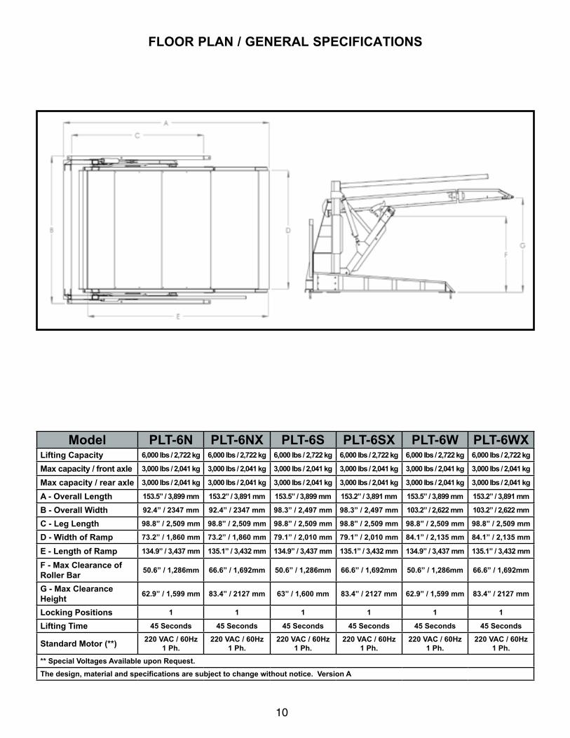
flOOR PlAN / GENERAl sPECIfICATIONs
Model PlT-6N PlT-6NX PlT-6s PlT-6sX PlT-6W PlT-6WXlifting Capacity 6,000 lbs / 2,722 kg 6,000 lbs / 2,722 kg 6,000 lbs / 2,722 kg 6,000 lbs / 2,722 kg 6,000 lbs / 2,722 kg 6,000 lbs / 2,722 kg
Max capacity / front axle 3,000 lbs / 2,041 kg 3,000 lbs / 2,041 kg 3,000 lbs / 2,041 kg 3,000 lbs / 2,041 kg 3,000 lbs / 2,041 kg 3,000 lbs / 2,041 kg
Max capacity / rear axle 3,000 lbs / 2,041 kg 3,000 lbs / 2,041 kg 3,000 lbs / 2,041 kg 3,000 lbs / 2,041 kg 3,000 lbs / 2,041 kg 3,000 lbs / 2,041 kg
A - Overall length 153.5” / 3,899 mm 153.2” / 3,891 mm 153.5” / 3,899 mm 153.2” / 3,891 mm 153.5” / 3,899 mm 153.2” / 3,891 mm
b - Overall Width 92.4” / 2347 mm 92.4” / 2347 mm 98.3” / 2,497 mm 98.3” / 2,497 mm 103.2” / 2,622 mm 103.2” / 2,622 mm
C - leg length 98.8” / 2,509 mm 98.8” / 2,509 mm 98.8” / 2,509 mm 98.8” / 2,509 mm 98.8” / 2,509 mm 98.8” / 2,509 mm
d - Width of Ramp 73.2” / 1,860 mm 73.2” / 1,860 mm 79.1” / 2,010 mm 79.1” / 2,010 mm 84.1” / 2,135 mm 84.1” / 2,135 mm
E - length of Ramp 134.9” / 3,437 mm 135.1” / 3,432 mm 134.9” / 3,437 mm 135.1” / 3,432 mm 134.9” / 3,437 mm 135.1” / 3,432 mm
f - Max Clearance of Roller bar 50.6” / 1,286mm 66.6” / 1,692mm 50.6” / 1,286mm 66.6” / 1,692mm 50.6” / 1,286mm 66.6” / 1,692mm
G - Max Clearance Height 62.9” / 1,599 mm 83.4” / 2127 mm 63” / 1,600 mm 83.4” / 2127 mm 62.9” / 1,599 mm 83.4” / 2127 mm
locking Positions 1 1 1 1 1 1
lifting Time 45 seconds 45 seconds 45 seconds 45 seconds 45 seconds 45 seconds
standard Motor (**) 220 vAC / 60Hz 1 Ph.
220 vAC / 60Hz 1 Ph.
220 vAC / 60Hz 1 Ph.
220 vAC / 60Hz 1 Ph.
220 vAC / 60Hz 1 Ph.
220 vAC / 60Hz 1 Ph.
** special voltages Available upon Request.The design, material and specifications are subject to change without notice. Version A

11
sTEP 3(base frame Assembly)
1. Place chalk lines on the floor according to the floor plan layout. Pay attention to the clearances needed with respect to the placement of your lift location. (See Fig 3.1)
2. Make sure chalk lines are square as this layout will be your guide when bolting the lift permanently in this location.
3. Place the Hose Channel Weldment upright (with the gussets upright) on the layout so that the rearmost edge of the Hose Channel Weldment touches the chalk line. Make certain that the Hose Channel Weldment is centered on the layout. (See Fig 3.2)
4. Locate the Left and Right Post Weldments. Place the Post Weldments within the chalk layouts, parallel with the Hose Channel Weldment, with the leg mounting plates facing upwards. When placing the post weldments inside the chalk layout, lay the bottom edge of the Left Post Weldment near the Left side chalk line and lay the bottom edge of the Right Post Weldment near the Right side chalk line. Both post straps on the two post weldments should be now facing the Hose Channel Weldment. (See Fig. 3.3)
5. Locate the Left and Right Leg Weldments. The Leg Weldments may be differentiated by looking at the foot pads located on the bottom of the legs. The side of the leg weldments with the straps welded on will be on the outside of the lift. The leg that has its straps on the left side when its foot pads are set on the floor is the Left Leg Weldment. The leg that has its straps on the right side when its foot pads are set on the floor is the Right Leg Weldment. (See Fig 3.4)
6. Place the Left Leg Weldment on top of the Left Post Weldment. Align the bolt pattens of the Left Leg Weldment and the Left Post Weldment. Place the Right Leg Weldment on top of the Right Post Weldment. Align the bolt pattens of the Right Leg Weldment and the Right Post Weldment. (See Fig. 3.5)
NOTE:IT MAY BE HELPFUL TO MEASURE YOUR CHALK LAYOUT DIAGONALLY TO CHECK FOR SQUARE.
Fig 3.1
Approach
Fig 3.2
Approach
Fig 3.3
Fig 3.4
Straps on outside of lift
Left Leg Weldment Shown
NOTE:IT MAY BE HELPFUL TO PLACE WOOD BLOCKS ,OR SIMILAR SPACING BLOCKS, UNDER THE LEFT AND RIGHT LEG WELDMENTS ON THE APPROACH END
OF THE LEGS TO HELP FACILITATE BOLT HOLE ALIGNMENT. USE CARE TO NOT SCRATCH THE
FINISH OF THE LIFT.
Post StrapsRight Post Weldment
Left Post Weldment

12
7. Using the provided M20 hardware, install six nuts, six bolts and six washers on both sides. (See Fig 3.6)
8. Raise the Left Post-Leg Assembly upright.(See Fig 3.7)
9. Locate the Power Unit Post Weldment.
10. Align the mounting holes of the Hose Channel Weld-ment, the Left Post-Leg Assembly and the Power Unit Post Weldment. Using the provided M20 hardware, install three nuts, three bolts, and three washers to mate the assembly together. (See Fig 3.8)
11. Repeat Items 8 and 9 of Step 3 for the mating of the Right Post-Leg Assembly and the Hose Channel Weld-ment.
12. The Base Frame Assembly is now complete. Do not anchor the Base Frame at this time. (See Fig 3.9)
Fig 3.5
Fig 3.6
Fig 3.8
Fig 3.7
Fig 3.9
WARNING!THIS STEP REQUIRES LIFTING OF VERY HEAVY COMPONENTS. BE SURE TO USE THE CORRECT LIFTING TOOLS SUCH AS A FORKLIFT OR CRANE TO POSITION COMPONENTS. PAY ATTENTION TO
COMPONENT POSITION ONCE COMPONENT IS LIFTED. ONCE LIFTED, COMPONENT IS A FALLING HAZARD. FAILURE TO USE THE CORRECT LIFTING
TOOLS OR TO PAY ATTENTION DURING LIFTING MAY RESULT IN PERSONAL INJURY OR DEATH. A
MINIMUM OF A TWO PERSON INSTALLATION TEAM IS RECOMMENDED FOR SAFE LIFTING PRACTICES.
Power Unit Post Weldment
Hose Channel
Weldment

13
sTEP 4(lift Arm Assembly)
1. Locate the Left and Right Lift Arm Weldments. The Lift Arms may be differentiated by the gusset orientation. The Lift Arm Gussets are always located on the outboard sides of the lift. (See Fig 4.1)
2. Locate the Roller Bar Weldment. The chamfered fea-ture of the ear plates will be facing towards the approach end of the lift. (See Fig. 4.2)
3. Assemble the Left and Right Lift Arm Weldments to the Roller Bar Weldment. Align the mounting holes and install eight sets of M10 nuts, bolts, and washers (four per arm) for both Left and Right sides. The two sets of bolts are left over for the Lift Arm Roller Pin installations. (See Fig 4.3 - 4.4)
4. Locate the Lift Arm Slide Blocks and Spacers. The Slide Blocks are to be installed with the flanges oriented away from the inside of the lift. Align the Slide Block holes with the pin thru holes in the Lift Arm Assembly. Insert the Slide Block Pins through the aligned holes and Spacers and fasten the Pins to the assembly with the remaining sets of M10 hardware. (See Fig 4.5)
5. The Lift Arm is now assembled. (See Fig 4.6)
Fig 4.1
Left Lift Arm Weldment Shown
Lift Arm Gusset
Fig 4.2
Approach
Chamfered Feature
Fig 4.3
Fig 4.4
Bolt hole reserved for Ramp Slide
Block Pin installation
M10 Nut
M10 Washer
M10 Bolt
Fig 4.5
M10 Nut
M10 WasherM10 x 40
Bolt
Slide BlockPin
Slide Block
Fig 4.6

14
sTEP 5(lift Arm Assembly Installation)
1. The Lift Arm Assembly will be assembled with two pivot pins and two retaining clips. Lift the Lift Arm Assembly, as completed in Step 4, into position so that both Lift Arm pivots are in between their respective arm clevises and align the holes. (See Fig. 5.1)
2. Once the bores are aligned with their respective thru holes, insert the Lift Arm Pivot Pin. The pins’ shoulders must be located on the “in” side of the lift. The notch in the pin’s shoulder should be fitted to the welded on pin stop.(See Fig. 5.2 - 5.3)
3. Once pins have been inserted, install the provided retaining clips to secure the pins in place. (See Fig. 5.4)
4. Using a Needle Point Lubrication Tool, inject lubricant into the hole in both Lift Arm Pivot Pins to lubricate the assembly. (See Fig. 5.5)
5. The Lift Arm Assembly installation is now complete.
WARNING!THIS STEP REQUIRES LIFTING OF A VERY HEAVY
COMPONENT. BE SURE TO USE THE CORRECT LIFTING TOOLS SUCH AS A FORKLIFT OR CRANE TO POSITION COMPONENTS. PAY ATTENTION TO
COMPONENT POSITION ONCE COMPONENT IS LIFTED. ONCE LIFTED, COMPONENT IS A FALLING HAZARD. FAILURE TO USE THE CORRECT LIFTING
TOOLS OR TO PAY ATTENTION DURING LIFTING MAY RESULT IN PERSONAL INJURY OR DEATH. A
MINIMUM OF A TWO PERSON INSTALLATION TEAM IS RECOMMENDED FOR SAFE LIFTING PRACTICES.
Fig 5.1
Fig 5.2
Fig 5.4
Fig 5.3
Fig 5.5
Inject Lubricant
Here

15
sTEP 6(Ramp Installation Preparation)
1. Locate the Post Rollers and slide one Post Roller down into each post. (See Fig 6.1)
2. Locate the two Leveling Bars and install them on to the Lift Arms. Find the Leveling Bar end with the two thru holes. Orient the Leveling Bar so that the bend is facing inward, place an Arm Spacer Bearing onto the pin, and slip the outermost hole over the Lift Arm Leveling Pin. (See Fig 6.2-6.3)
3. Secure the Leveling Bars to the Lift Arm Leveling Pins with a E-Ring retaining ring. (See Fig 6.3)
sTEP 7(Ramp & safety bar Installation)
1. Locate the two Ramp Channel Weldments. The Left and Right side may be differentiated by the Post Roller Plate at the rear and the open section of channel of each Ramp Side Weldment facing the outside of the lift. (See Fig 7.1)
2. Insert a Post Roller Pin through each of the two Roller Plates on the two Ramp Channel Weldments. (See Fig 7.2)
3. Install four M10 x 25 bolts to secure the Post Roller Pins on to both Ramp Channel Weldments. (See Fig 7.3)
Fig 6.1
NOTE:GREATER UNDERRAMP CLEARANCE MAY BE
POSSIBLE WHEN THE LEVELING BAR IS INSTALLED SO THAT THE LIFT ARM LEVELING PIN IS IN
THE INNERMOST HOLE POSITION. THIS WILL INCREASE THE RAMP LIFTING ANGLE.
WARNING!MAKE CERTAIN THE TWO LEVELING BARS ARE IN THE SAME PIN POSITION PRIOR TO OPERATION OF LIFT. FAILURE TO ENSURE BOTH BARS ARE IN THE SAME PIN POSITION WILL CAUSE LIFT
MALFUNCTION AND VOID WARRANTY.
Fig 6.2
Lift Arm Leveling Pin
Fig 7.1
LEFT RAMP SIDE WELDMENT
Post Roller Plate
Fig 7.2
Fig 7.3
Fig 6.3
Arm Spacer Bearing
E-Ring
16
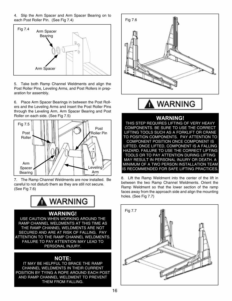
4. Slip the Arm Spacer and Arm Spacer Bearing on to each Post Roller Pin. (See Fig 7.4)
5. Take both Ramp Channel Weldments and align the Post Roller Pins, Leveling Arms, and Post Rollers in prep-aration for assembly.
6. Place Arm Spacer Bearings in between the Post Roll-ers and the Leveling Arms and insert the Post Roller Pins through the Leveling Arm, Arm Spacer Bearing and Post Roller on each side. (See Fig 7.5)
7. The Ramp Channel Weldments are now installed. Be careful to not disturb them as they are still not secure.(See Fig 7.6)
8. Lift the Ramp Weldment into the center of the lift in between the two Ramp Channel Weldments. Orient the Ramp Weldment so that the lower section of the ramp faces away from the approach side and align the mounting holes. (See Fig 7.7)
Fig 7.4Arm Spacer
Bearing
Arm Spacer
Fig 7.5Post
Roller Pin
Leveling Arm
Arm Spacer Bearing
Post Roller
WARNING!USE CAUTION WHEN WORKING AROUND THE
RAMP CHANNEL WELDMENTS AT THIS TIME AS THE RAMP CHANNEL WELDMENTS ARE NOT
SECURED AND ARE AT RISK OF FALLING. PAY ATTENTION TO THE RAMP CHANNEL WELDMENTS.
FAILURE TO PAY ATTENTION MAY LEAD TO PERSONAL INJURY.
NOTE:IT MAY BE HELPFUL TO BRACE THE RAMP CHANNEL WELDMENTS IN THEIR CURRENT
POSITION BY TYING A ROPE AROUND EACH POST AND RAMP CHANNEL WELDMENT TO PREVENT
THEM FROM FALLING.
Fig 7.6
WARNING!THIS STEP REQUIRES LIFTING OF VERY HEAVY COMPONENTS. BE SURE TO USE THE CORRECT LIFTING TOOLS SUCH AS A FORKLIFT OR CRANE TO POSITION COMPONENTS. PAY ATTENTION TO
COMPONENT POSITION ONCE COMPONENT IS LIFTED. ONCE LIFTED, COMPONENT IS A FALLING HAZARD. FAILURE TO USE THE CORRECT LIFTING
TOOLS OR TO PAY ATTENTION DURING LIFTING MAY RESULT IN PERSONAL INJURY OR DEATH. A
MINIMUM OF A TWO PERSON INSTALLATION TEAM IS RECOMMENDED FOR SAFE LIFTING PRACTICES.
Fig 7.7

17
9. Install six sets of M10 bolts, washers, and nuts to fas-ten the Ramp Weldment to the Ramp Side Weldments.(See Fig 7.8)
10. Install the four Deck Channel Weldments next. Ori-ent the Deck Channel Weldments so that the “open” side of the channel face towards the ground. Use M10 bolts, washers, and nuts to fasten the Deck Channel Weldments to the Ramp Side Weldments. (See Fig 7.9)
11. Place the Deck Plates on top of the Deck Channel Weldments. The “lip” of the Front Deck Plate will overlap the Center Deck Plate. The Center Deck Plate “lip” will overlap the Ramp Weldment. Align the mounting holes and use the M6 Pan Head Phillips Screws, M6 spring lock washers, and M6 nuts to mount the Deck Plates to the Deck Channels. (See Fig 7.10 - 7.11)
12. Ramp installation is now complete. (See Fig 7.12)
sTEP 8(Tire stop bar Installation)
1. Locate the Tire Stop Bar Weldments. Orient the Tire Stop Bar so that the bar angles away from the lift and align the mounting holes. (See Fig 8.1)
2. Use the supplied M10 bolts, washers, and hex nuts to securely fasten the Tire Stop Bar to the Ramp Assembly. (See Fig 8.2)
Fig 7.8
Fig 7.9
Fig 7.10
Fig 7.11
Fig 7.12
Fig 8.1
M6 Phillips Screw
M6 Washer
M6 Nut

18
sTEP 9(drive-up Ramp Installation)
1. Locate the Drive-Up Ramp Weldment. Orient the Drive-Up Ramp so that the bars protruding from the Drive-Up Ramp point towards the Ramp Assembly. (See Fig 9.1)
2. Install a M12 x 70mm adjustment screw and jam nut to each side of the Drive-Up Ramp. (See Fig 9.2)
3. Lift the Drive-Up Ramp Weldment and align the thru holes of the Drive-Up Ramp bars to the Ramp Assembly. The bars should slide in between the strap and the ramp channel on both Ramp Channels. (See Fig 9.3)
4. Place a Drive-Up Ramp Pin through each of the aligned holes to fasten the Drive-Up Ramp to the Ramp Assembly. (See Fig 9.4)
5. Secure the Drive-Up Ramp Pins by installing E-Ring retaining rings in the snap ring grooves in the pins. (See Fig 9.5)
Fig 8.2
Fig 9.1
WARNING!THIS STEP REQUIRES LIFTING OF A VERY HEAVY
COMPONENT. BE SURE TO USE THE CORRECT LIFTING TOOLS SUCH AS A FORKLIFT OR CRANE TO POSITION COMPONENT. PAY ATTENTION TO COMPONENT POSITION ONCE COMPONENT IS
LIFTED. ONCE LIFTED, COMPONENT IS A FALLING HAZARD. FAILURE TO USE THE CORRECT LIFTING
TOOLS OR TO PAY ATTENTION DURING LIFTING MAY RESULT IN PERSONAL INJURY OR DEATH. A
MINIMUM OF A TWO PERSON INSTALLATION TEAM IS RECOMMENDED FOR SAFE LIFTING PRACTICES.
Fig 9.2
Fig 9.3
Fig 9.4
Fig 9.5

19
sTEP 10(Cylinder Installation)
1. To install a cylinder, align the thru holes of the Cylinder Clevis of the Cylinder Tube end and the Cylinder Clevis Brackets. Install Cylinder Clevis Pin through the thru holes and secure pin with 2 E-Rings. Make sure the Cylinder Hy-draulic Ports face toward the post. (See Fig 10.1)
2. Install the Rod End Connector to the Cylinder Rod if it has not been installed already. Thread Rod End Connector on to Cylinder Rod until Connector threads are fully en-gaged. (See Fig 10.2)
3. In order to connect the Rod End Connector to the lift it is necessary to first extend the Hydraulic Cylinder. Remove both Cylinder port plugs then use an air gun or come-along to extend the Cylinder. Once fully extended, align the thru holes of the Rod End Connector and the Clevis Plates of the Lift Arm. Insert the Lift Arm Clevis Pin through the holes and secure it with 2 E-Rings. Install the Rubber Grommet into to hole in the Leg Weldment at this time, if it has not been installed already. (See Fig 10.3 - 10.4)
4. Install the supplied 90° -04 JIC to -06 NPT fitting to the lower port and the 90° Push-to-connect Air Fitting to the upper port. Apply Teflon tape to the NPT threads on the fitting prior to installation. (See Fig 10.5)
Fig 10.1
Cylinder Ports
Fig 10.2
Fig 10.4
Fig 10.3
Fig 10.5
Rubber Tip Air Gun
DO NOT exceed 50 PSI. If cylinder does not moveImmediately STOP and use a come-along or other
Pulling devise. Keep hands clear.
Hydraulic Fitting
Air Fitting

20
5. Repeat Items 1 - 4 to install the second cylinder.
6. Cylinder installation is now complete. (See Fig 10.6)
sTEP 11(Control Arm Installation)
1. Locate the Control Arm Weldment and align mount-ing holes with the mounting holes on the Post Weldment. Make sure the Control Arm is oriented so that the Arm Tube is angled upwards. NOTE: It may be helpful to route the Control Pendant cable at this time. (See Fig 11.1)
2. Bolt the Control Arm Weldment and the Post Weldment together using the supplied M10 bolts, nuts, and washers. NOTE: Make sure to insert the 140mm long bolt through the top hole in BOTH SIDES of the post and the 25mm long bolt through the bottom hole. (See Fig 11.2)
sTEP 12(lift Anchoring)
1. Before proceeding, make certain the lift is positioned with proper clearances around and overhead. (See clear-ances section on page 4)
2. Locate the 4 anchor points. (See Fig. 12.1)
3. Using the Foot Pad as a guide, drill each anchor hole in the concrete (approximately 4” deep) using a rotary hammer drill and 3/4” concrete drill-bit. To ensure full holding power, do not ream the hole or allow the drill to wobble. (See Fig. 12.2)
NOTE:THE CONTROL ARM MAY BE INSTALLED ON
EITHER THE RIGHT OR LEFT HAND SIDE OF THE LIFT. FOR CLARITY THIS MANUAL WILL ONLY
SHOW THE CONTROL ARM INSTALLED ON THE LEFT SIDE OF THE LIFT.
Fig 11.1
Fig 11.2
Fig 10.6
IMPORTANT NOTE:BendPak lifts are supplied with installation
instructions and concrete fasteners meeting the criteria as prescribed by the American National
standard "Automotive lifts - safety Requirements for Construction, Testing, and validation" ANsI/AlI AlCTv-2006. lift buyers are responsible for any
special regional structural and/or seismic anchoring requirements specified by any other agencies and/or
codes such as the uniform building Code (ubC) and/or International building Code (IbC).
Fig 12.1
M10 x 140 Hex Bolt

21
4. After drilling the anchor holes, remove the dust thor-oughly from each hole using compressed air and/or wire brush. (See Fig 12.3)
5. Assemble the washers and nuts on the anchors then tap into each hole with a hammer until the washer rests against the base. (See Fig. 12.4 - 12.5)
6. With the anchor bolts in place, tighten nut three to five turns past finger tight. DO NOT use an impact wrench for this procedure. (See Fig. 12.6)
7. The Post restraints (if any were used) may now be removed.
8. Attach the Tire Guard Weldments using M10 x 25 hex bolts, nuts and washers. Make sure that the open side of the Guard faces the OUTSIDE of the lift. (See Fig 12.7)
Fig 12.2
Fig 12.5
Fig. 12.3
Fig 12.4
Fig 12.6
Fig 12.7
M10 x 25 Hex Bolt

22
IMPORTANT POWER-uNIT INsTAllATION NOTEs
nDO NOT run power unit without oil. Damage to pump can occur.nThe power unit must be kept dry. Damage to power unit caused by water or other liquids such as detergents, acid etc., is not covered under warranty.nImproper electrical connection can damage motor and will not be covered under warranty.nMotor can not run on 50HZ without a physical change in the motor.nUse a separate breaker for each power unit.nProtect each circuit with time delay fuse or circuit breaker.nFor 208-230 volt, single phase, use a 25 amp fuse.
Installation and adjustment: DO NOT attempt to raise vehicle until a thorough operation check has been completed.
All wiring must be performed by a certified electrician.
dANGER!DO NOT PERFORM ANY MAINTENANCE OR INSTALLATION OF ANY COMPONENTS WITH OUT FIRST ENSURING THAT ELECTRICAL POWER HAS BEEN DISCONNECTED AT THE
SOURCE OR PANEL AND CANNOT BE RE-ENERGIZED UNTIL ALL MAINTENANCE AND/OR INSTALLATION
PROCEDURES ARE COMPLETED.

23
sTEP 13(Power Unit Electrical Connection)
1. Have a certified electrician run the power supply to motor. Refer to the data plate found on the motor for proper power supply and wire size. SEE WIRING INSTRUCTIONS AFFIXED TO MOTOR FOR PROPER WIRING INSTRUCTIONS.
sTEP 14(Hydraulic, Air and Electrical line
Routing)1. Mount the Power Unit and Vibration Dampener to the Power Unit Post Weldment using the M8 hex bolts and Nylock Nuts. Fill the reservoir with 4 gallons of 10-WT hydraulic oil or Dexron III automatic transmission fluid. (See Fig. 14.1)
2. Remove the shipping plugs from both ports prior to installing the fittings. Install the 90°Hydraulic Fitting to the POWER PORT and the 90° Air Fitting to the RETURN PORT of the Power Unit. On the pipe thread side of the Air Fitting it is recommended to use Teflon tape or pipe sealer. (See Fig. 14.2)
WARNING!DO NOT RUN POWER UNIT WITHOUT OIL. DAMAGE TO
POWER UNIT PUMP CAN OCCUR. THE POWER UNIT MUST BE KEPT DRY. DAMAGE TO POWER UNIT CAUSED BY WATER OR OTHER LIQUIDS SUCH AS DETERGENTS,
ACID ETC., IS NOT COVERED UNDER WARRANTY.
OPERATE LIFT ONLY BETWEEN TEMPERATURES OF 41 °- 104° F. IMPROPER ELECTRICAL HOOK-UP CAN
DAMAGE MOTOR AND WILL NOT BE COVERED UNDER WARRANTY. MOTOR CAN NOT RUN ON 50HZ WITHOUT
A PHYSICAL CHANGE IN THE MOTOR.
USE A SEPARATE CIRCUIT BREAKER FOR EACH POWER UNIT. PROTECT EACH CIRCUIT WITH TIME DELAY FUSE
OR CIRCUIT BREAKER.
FOR 208-230 VOLT, SINGLE PHASE, USE A 25 AMP FUSE.
dANGER!DO NOT PERFORM ANY MAINTENANCE OR
INSTALLATION OF ANY COMPONENTS WITHOUT FIRST ENSURING THAT ELECTRICAL POWER HAS
BEEN DISCONNECTED AT THE SOURCE OR PANEL AND CANNOT BE RE-ENERGIZED UNTIL ALL
MAINTENANCE AND/OR INSTALLATION PROCEDURES ARE COMPLETED.
dANGER !ALL WIRING MUST BE PERFORMED
BY A LICENSED ELECTRICIAN.
dANGER!RISK OF EXPLOSION! THIS EQUIPMENT HAS
INTERNAL ARCING OR PARTS THAT MAY SPARK AND SHOULD NOT BE EXPOSED TO FLAMMABLE VAPORS. MOTOR SHOULD NOT BE LOCATED IN A RECESSED AREA OR BELOW FLOOR LEVEL.
NEVER EXPOSE MOTOR TO RAIN OR OTHER DAMP ENVIRONMENTS. DAMAGE TO MOTOR CAUSED BY
WATER IS NOT COVERED UNDER WARRANTY.
Fig. 14.1
M8 Nylock Nut
M8 Bolt
Vibration Dampener
Fig. 14.2
Air Fitting
90° Hydraulic Fitting
Power Port
Return Port

24
3. Connect one end of the Power Side Hose and the 90° end of the Off Side Hose to the Tee Fitting. Connect the Male-to-Female 90° fitting to the tee Fitting. Connect the Power Unit Hose to the 90° fitting. (See Fig. 14.3)
4. Route the Power Side and Off Side hoses through the Rubber Grommets that were installed in Step 10 and con-nect the hoses to the JIC elbow fittings on the cylinders. DO NOT use Teflon tape on the JIC fitting end. (See Fig. 14.4)
5. Connect the 1/4” air line tubing to the 90° Air Fittings and Air Tee Fitting using the same routes used for the Hydraulic Hoses. Cut the air line tubing with a sharp blade to lengths as required. Tubing must be cut square with no burrs. Note: To assemble air line tubing into fittings, use firm, manual pressure to push tubing into the fitting until it bot-toms out. To remove air line tubing from the fitting, hold push sleeve in (against fitting) and, at the same time, pull out on tubing. Pay careful attention to keep air line clear of any pinch points.
6. Install the provided Liquid Tight Conduit and Fittings. (See Fig 14.5)
7. Route the Electrical Cable from the Control Pendant through the Control Arm Weldment and Conduit to the Power Unit and connect according to the wiring diagram found on page 22.
sTEP 15(lift start up)
1. Make sure the Power Unit reservoir is full with four (4) gallons of 10-WT hydraulic oil or Dexron-III automatic transmission fluid.
2. Spray the inside of the posts with a light spray-oil.
3. Connect power supply and test the Power Unit by pressing the Up push-button switch on the Control Pendant. If the motor sounds like it is operating properly, raise the lift and check all hose connections for leaks. If the motor gets hot or sounds peculiar, STOP and check all electrical connections.
4. Raise lift until each cylinder is fully retracted and the lift stops. Place support stands or a fork lift underneath the ramp to support it during the next step.
sTEP 16(safety Installation)
1. With the ramp raised and supported securely, locate the Safety Weldment and Safety Bar Strap.
Fig. 14.4
Fig. 14.5
Fig. 14.3
Off Side Hose
Male-to-Female 90°
Fitting
Power Unit Hose
Power Side Hose
Tee Fitting
Rubber Grommet
JIC Elbow Fitting
dANGER!Because the safety has not been installed yet, DO
NOT work on or near raised lift until support stands are in place to support the platform. Always ensure sup-
port stands are engaged before any attempt is made to work on or near the lift / vehicle.
Liquid Tight Fittings
Liquid Tight Conduit
Liquid Tight Conduit

25
2. Place the Safety Weldment under the ramp so that the Safety Latches are on the outside of the Ramp Channels. Fasten the Safety Weldment to the Ramp Channels using the Safety Bar Straps and the provided M10 hex bolts and nylock nuts. (See Fig 16.1)NOTE: It is recommended to bolt the Safety on the last position on the channels to ensure proper safety engage-ment.
3. Once the Safety is connected to the lift, lower the lift by pressing the Down push button on the Control Pendant until the lift stops. The lift should now be resting on the safeties. If it is not, lower the lift all the way to the ground and make sure the lift did not shift during installation and test the safety again.
4. Install one Bulkhead Terminal in the hole in the Ramp Channel after the Safety Bar Strap and the other in the Cable Standoff Plate in the Drive Up ramp on the same side of the lift. (See Fig 16.2)
5. Locate the Safety Arm, Safety Wheel, Wire Rope Conduit Assembly and Safety Spring.
6. Attach the Safety Arm to the Drive Up Ramp using the M10 x 38 hex bolt, two jam nuts, spring lock washer and Small Spacer. (See Fig 16.3)
7. Assemble Safety Spring on the M10 x 50 hex bolt using a jam nut, nylock nut and Long Spacer. Assemble the Safety Wheel using the M8 nylock nut. (See Fig 16.4)
8. Insert the Wire Rope Conduit Assembly into the Drive Up Ramp Bulkhead Terminal and feed the push/pull cable through the small hole in its head. Slide the cable crimp on and make a small loop in the cable and crimp with pli-ers. After this is done, hook the spring to the cable. (See Fig 16.5)
9. Insert the other end of the Wire Rope Conduit Assembly into the Ramp Channel Bulkhead Terminal and feed the push/pull cable through the small hole in its head. (See Fig 16.6)
10. Thread one M6 hex nut and washer onto the threaded shaft past the hole in the shaft. Then insert the cable end through the hole. Thread the other nut and washer onto the shaft and tighten while making sure the cable is cen-tered in the hole. (See Fig 16.7)
Fig. 16.1
Fig. 16.5
Fig. 16.3
M10 x 38 Hex Bolt
Small Spacer
M10 Spring Lock Washer
Fig. 16.2
M10 Jam Nut Safety Arm
Weldment
M10 Nylock Nut
Safety Bar Strap
M10 x 25 Hex Bolt
M10 Washer Fig. 16.4
Large Spacer
M10 Jam Nut
Safety Wheel
M10 x 50 Hex Bolt
Safety Spring
M10 Nylock Nut
M8 Nylock Nut

26
sTEP 17(bleeding the Cylinder)
1. Lift must be fully lowered before changing or adding fluid.
2. Raise and lower lift six times. The cylinder is self-bleed-ing. After bleeding system, fluid level in Power Unit reser-voir may be low. Add more fluid, if necessary, to raise lift to full height. It is only necessary to add fluid to raise lift to full height.
3. To pressure test, raise lift to full rise and run motor for approximately 3-seconds after lift stops. This will put pres-sure on the hydraulic system. Stop and check all fittings and hose connections. Tighten or reseal if required.
POsT-INsTAllATION CHECKlIsT• Anchor bolts tightened• Pivot pins properly attached• Electric power supply confirmed• Safety locks functioning properly• Check for hydraulic leaks• Oil level• Lubrication of critical components• Check for overhead obstructions• All screws, bolts, and pins secured• Surrounding area clear• Operation, maintenance and safety manuals on site
sTEP 18(Operation)
To Raise lift:1. Load vehicle onto the lift as far forward on the lift as possible.
2. Set parking brake to hold vehicle in position.
3. Before raising vehicle, be sure all personnel are clear of the lift and surrounding area. Pay careful attention to overhead clearances.
4. Raise the lift to the Safety Lock height by pressing the UP BUTTON on the Control Pendant.
5. After vehicle is raised to the Safety Lock height, lower the lift onto the safety lock. AlwAYS ENSURE ALL SAFETY LOCKS ARE ENGAGED before entering lift area.
To Lower Lift:1. Before lowering vehicle, be sure all personnel are clear of the lift and surrounding area. Pay careful attention to overhead clearances. Ensure all tools and equipment have been cleared from under the lift.
2. Raise the lift off of the safety locks by pressing the push button on the Control Pendant. Make sure to raise the lift by at least two inches to allow adequate clearance for the locks to clear.
3. Manually release the Safety Arm by lowering it into the down position.
4. Push the DOWN BUTTON on the Control Pendant until the lift has descended completely.
When lowering the lift, PAY CAREFUl ATTENTION that all personnel and objects are kept clear. AlwAYS keep a visual line of sight on the lift AT All TIMES. AlwAYS make sure that All lOCkS are disengaged. If the locks inadvertently locks on descent, the lift and/or vehicle may
disrupt causing personal injury or death.
Fig. 16.6
Fig. 16.7Route safety cable the hole in the threaded
shaft
Tighten jam nuts ensuring safety cable is
centered in hole

27
safe lift OperationAutomotive and truck lifts are critical to the operation and profitability of your business. The safe use of this and other lifts in your shop is critical in preventing employee injuries and damage to customer’s vehicles. By operating lifts safely you can insure that your shop is profitable, productive and safe. Safe operation of automotive lifts requires that only trained employees should be allowed to use the lift.
Training should include, buT noT limiTed To:tProper positioning of the vehicle on the runway. (See manufacturers minimum wheel base loading requirements.)
tUse of the operating controls.
tUnderstanding the lift capacity.
tProper use of jack stands or other load supporting devices.
tProper use, understanding and visual identification of safety lock devices and their operation.
tReviewing the safety rules.
tProper housekeeping procedures. (Lift area should be free of grease, oil, tools, equipment, trash, and other debris.)
tA daily inspection of the lift should be completed prior to its use. Safety devices, operating controls, lift arms and other critical parts should be inspected prior to using the lift.
tAll maintenance and repairs of the lift should be completed by following the manufacturer’s requirements. Lift repair parts should meet or exceed OEM specifications. Repairs should only be completed by a qualified lift technician.
tThe vehicle manufacturer’s recommendations should be used for spotting and lifting the vehicle.
lifT operaTion safeTy
t It is important that you know the load limit. Be careful that you do not overload the lift . If you are unsure what the load limit is, check the data plate found on one of the lift columns or contact the manufacturer.
tThe center of gravity should be followed closely to what the manufacturer recommends.
tAlways make sure you have proper overhead clearance. Additionally, check that attachments (vehicle signs, campers, antennas, etc.) are not in the way.
tBe sure that prior to the vehicle being raised, the doors, trunk, and hood are closed securely.
tPrior to being raised, make sure there is no one standing closer than six feet from the lift.
tAfter positioning the vehicle on the lift runways, set the emergency brake, make sure the ignition is off, the doors are closed, overhead obstructions are cleared, and the transmission is in park (neutral for manual transmissions).
tDouble check that the automatic chock devices are in position, and then when the lift is raised, observe the chocks. tThe lift should be raised just until the vehicle’s wheels are about one foot off the ground. If contact with the vehicle is uneven or it appears that the vehicle is not sitting secure, carefully lower the lift and readjust.
tAlways consider potential problems that might cause a vehicle to slip, i.e., heavy cargo, undercoating, etc.
tPay attention when walking under a vehicle that is up on the hydraulic lift.

28
tdO NOT leave the controls while the lift is still in motion.
tdO NOT stand directly in front of the vehicle or in the bay when vehicle is being loaded or driven into position.
tdO NOT go near vehicle or attempt to work on the vehicle when being raised or lowered.
t REMAIN ClEAR of lift when raising or lowering vehicle.
tdO NOT rock the vehicle while on the lift or remove any heavy component from vehicle that may cause excessive weight shift.
tdO NOT lower the vehicle until people, materials, and tools are clear.
tAlWAys ENsuRE that the safeties are engaged and lowered onto the safety pins before any attempt is made to go near the bottom vehicle.
tREAd ANd uNdERsTANd all safety warning procedures before operating lift.
tKEEP HANds ANd fEET ClEAR. Remove hands and feet from any moving parts. Keep feet clear of lift when lowering. Avoid pinch points.
tONly TRAINEd OPERATORs should operate this lift. All non-trained personnel should be kept away from work area. Never let non-trained personnel come in contact with, or operate lift.
tusE lIfT CORRECTly. Use lift in the proper manner. Never use lifting adapters other than what is approved by the manufacturer.
tdO NOT override self-closing lift controls.
tClEAR AREA if vehicle is in danger of falling.
tsTAy AlERT. Watch what you are doing. Use common sense. Be aware.
tCHECK fOR dAMAGEd PARTs. Check for alignment of moving parts, breakage of parts or any condition that may affect its operation. Do not use lift if any component is broken or damaged.
tNEvER remove safety related components from the lift. Do not use lift if safety related components are damaged or missing.
tWhen the lift is being lowered, make sure everyone is standing at least six feet away.
tBe sure there are no jacks, tools, or equipment left under the lift before lowering.
tAlways lower the vehicle slowly and smoothly.
safe lift Operation (Cont’d)

29
3030

3131

32

33

34
lIfT WIll NOT RAIsE
possible cause1. Air in oil (1,2,8,13)2. Cylinder binding (9)3. Cylinder leaks internally (9)4. Motor run backward under pressure (11)5. Lowering valve leaks (3,4,6,10,11)6. Motor runs backwards (7,14,11)7. Pump damaged (10,11)8. Pump won’t prime (1,8,13,14,3,12,10,11)9. Relief valve leaks (10,11)10. Voltage to motor incorrect (7,14,11)
remedy insTrucTion1. Check for proper oil level. . . . . . . . . . . . . . . . . . . . . . . . . . The oil level should be up to the bleed screw in the reservoir with the lift all the way down.
2. Bleed cylinders. . . . . . . . . . . . . . . . . . . . . . . . . . . . . . . . . . See Installation Manual
3. Flush release valve to get rid of. . . . . . . . . . . . . . . . . . . . . Hold release handle down and start unit allowing possible contamination it to run for 15 seconds.
4. Dirty oil. . . . . . . . . . . . . . . . . . . . . . . . . . . . .. . . . . . . . . . . . Replace oil with clean Dexron ATF.
5. Tighten all fasteners. . . . . . . . . . . . . . . . . . . . . . . . . . . . . . . Tighten fasteners to recommended torques (see chart on pg. 38).
6. Check for free movement of release. . . . . . . . . . . . . . . . . . . If handle does not move freely, replace bracket or handle assembly. 7. Check if motor is wired correctly. . . . . . . . . . . . . . . . . . . . . . .Compare wiring of motor to electrical diagram on drawing.
8. Oil seal damaged or cocked . . . . . . . . . . . . . . . . . . . . . . . . Replace oil seal around pump shaft.
9. See Installation Manual . . . . . . . . . . . . . . . . . . . . . . . . . . . . Contact BendPak Customer Support.
10. Replace with new part . . . . . . . . . . . . . . . . . . . . . . . . . . . . . Replace with new part.
11. Return unit for repair . . . . . . . . . . . . . . . . . . . . . . . . . . . . . . Return unit for repair.
12. Check pump-mounting bolts . . . . . . . . . . . . . . . . . . . . . . . . Bolts should be 15 to 18 ft. lbs.
13. Inlet screen clogged . . . . . . . . . . . . . . . . . . . . . . . . . . . . . . Clean inlet screen or replace.
14. Check wall outlet voltages and wiring . . . . . . . . . . . . . . . . . Make sure unit and wall outlet are wired properly.

35
MOTOR WIll NOT RuN
possible cause1. Fuse blown (5,2,1,3,4)2. Limit switch burned out (1,2,3,4)3. Microswitch burned out (1,2,3,4)4. Motor burned out (1,2,3,4,6)5. Voltage to motor incorrect (2,1,8)
remedy insTrucTion1. Check for correct voltage . . . . . . . . . . . . . . . . . . . . . . . . . . .Compare supply voltage with voltage on motor name tag. Check that the wire is sized correctly. N.E.C. table 310-12 requires AWG 10 for 25 Amps. 2. Check motor is wired correctly . . . . . . . . . . . . . . . . . . . . . . .Compare wiring of motor to electrical diagram on drawing.
3. Don’t use extension cords . . . . . . . . . . . . . . . . . . . . . . . . . . According to N.E.C. : “ The size of the conductors… should be such that the voltage drop would not exceed 3% to the farthest outlet for power…” Do not run motor at 115 VAC – damage to the motor will occur.
4. Replace with new part . . . . . . . . . . . . . . . . . . . . . . . . . . . . .Replace with new part.
5. Reset circuit breaker/fuse . . . . . . . . . . . . . . . . . . . . . . . . . .Reset circuit breaker/fuse.
6. Return unit for repair . . . . . . . . . . . . . . . . . . . . . . . . . . . . . Return unit for repair.
7. See Installation Manual . . . . . . . . . . . . . . . . . . . . . . . . . . . .See Installation Manual.
8. Check wall outlet voltage and wiring . . . . . . . . . . . . . . . . . . Make sure unit and wall outlet is wired properly. Motor must run at 208/230 VAC.
lIfT lOWERs slOWly OR NOT AT All
possible cause1. Cylinders binding, (1)2. Release valve clogged, (5,4,2,3)3. Pressure fitting too long, (6)
remedy insTrucTion1. See Installation Manual . . . . . . . . . . . . . . . . . . . . . . . . . . . Contact BendPak Customer Support.
2. Replace with new part . . . . . . . . . . . . . . . . . . . . . . . . . . . . Replace with new part.
3. Return for repair . . . . . . . . . . . . . . . . . . . . . . . . . . . . . . . . . Return for repair.
4. Check oil. . . . . . . . . . . . . . . . . . . . . . . . . . . . . . . . . . . . . . Use clean 10-WT hydraulic oil or Dexron-III automatic transmission fluid only. If ATF is contaminated, replace with clean ATF and clean entire system.
5. Clean release valve . . . . . . . . . . . . . . . . . . . . . . . . . . . . . . . . Wash release valve in solvent and blow out with air.
6. Replace fitting with short thread lead . . . . . . . . . . . . . . . . . . . Replace fitting with short thread lead.

36
WIll NOT RAIsE lOAdEd lIfT
possible cause1. Air in oil (1,2,3,4)2. Cylinder binding (5)3. Cylinder leaks internally (5)4. Lift overloaded (6,5)5. Lowering valve leaks (7,8,1,5,9)6. Motor runs backwards (10,12,9)7. Pump damaged (5,9)8. Pump won’t prime (1,2,3,4,5,11,9)9. Relief valve leaks (8,5,9)10. Voltage to motor incorrect (10,12,5)
remedy insTrucTion1. Check oil level . . . . . . . . . . . . . . . . . . . . . . . . . . . . . . . . . . The oil level should be up to the bleed screw in the reservoir with the lift all the way down.
2. Check/Tighten inlet tubes . . . . . . . . . . . . . . . . . . . . . . . . . . Replace inlet hose assembly.
3. Oil seal damaged or cocked . . . . . . . . . . . . . . . . . . . . . . . . Replace oil seal and install.
4. Bleed cylinders . . . . . . . . . . . . . . . . . . . . . . . . . . . . . . . . . . See Installation Manual.
5. See Installation Manual . . . . . . . . . . . . . . . . . . . . . . . . . . . . Contact BendPak Customer Support.
6. Check vehicle weight . . . . . . . . . . . . . . . . . . . . . . . . . . . . . Compare weight of vehicle to weight limit of the lift.
7. Flush release valve . . . . . . . . . . . . . . . . . . . . . . . . . . . . . Hold release handle down and start unit allowing it to run for 15 seconds.
8. Replace with new part . . . . . . . . . . . . . . . . . . . . . . . . . . . . . Replace with new part.
9. Return unit for repair . . . . . . . . . . . . . . . . . . . . . . . . . . . . . . Return unit for repair.
10. Check motor is wired correctly . . . . . . . . . . . . . . . . . . . . . . . Compare wiring of motor to electrical diagram on power unit drawing.
11. Inlet screen clogged . . . . . . . . . . . . . . . . . . . . . . . . . . . . . . Clean inlet screen or replace.
12. Check wall outlet voltage and wiring . . . . . . . . . . . . . . . . . . Make sure unit and wall outlet is wired properly.

37
lIfT WIll NOT sTAy uPpossible cause1. Air in oil (1,2,3)2. Check valve leaks (6)3. Cylinders leak internally (7)4. Lowering valve leaks (4,5,1,7,6)5. Leaking fittings (8)
remedy insTrucTion1. Check oil level . . . . . . . . . . . . . . . . . . . . . . . . . . . . . . . . . . . The oil level should be up to the bleed screw in the reservoir with the lift all the way down.
2. Oil seal damaged and cocked . . . . . . . . . . . . . . . . . . . . . . . . Replace oil seal around pump shaft.
3. Bleed cylinder . . . . . . . . . . . . . . . . . . . . . . . . . . . . . . . . . . . . Refer to Installation Manual.
4. Flush release valve . . . . . . . . . . . . . . . . . . . . . . . . . . . . . . . . Hold release handle down and start unit allowing it to run for 15 seconds.
5. Replace with new valve . . . . . . . . . . . . . . . . . . . . . . . . . . . . . Replace with new valve.
6. Return unit for repair . . . . . . . . . . . . . . . . . . . . . . . . . . . . . . . Return unit for repair.
7. See Installation Manual . . . . . . . . . . . . . . . . . . . . . . . . . . . . . Contact BendPak Customer Support.
8. Check complete hydraulic system for leaks. . . . . . . . . . . . . . Tighten all hydraulic fittings and inspect all hoses.

38
lubrication locations
vAluEs ARE sTATEd IN fOOT POuNds (ft-lb)
SAE 0-1-2 SAE Grade 5 SAE Grade 8 SOCKET HEAD CAP SCREW
CLASS 4.8 CLASS 8.8 CLASS 10.9 CLASS 12.9
bolt size (sAE)
bolt size (Metric)
1/4-20 M6 x 1.0 6 10 14 13
5/16-18 M8 x 1.25 12 19 29 31.4
3/8-16 M10 x 1.50 20 33 47 62
7/16-14 32 54 78
1/2-13 M12 x 1.75 47 78 119 108
9/16-12 M14 x 2.00 69 114 169 173
5/8-11 M16 x 2.00 96 154 230 269
3/4-10 M18 x 2.50 155 257 380 372
7/8-9 M22 x 2.50 206 382 600 716
Inject Lubricant Here
Inject Lubricant
Here
Inject Lubricant
Here
Lubricate Inside of Posts
NOTE: Lubrication procedure should be performed on both the right side and left side of the lift.
Torque Recommendations

39
Maintenance
If you are not completely familiar with parking lift maintenance procedures STOP and contact factory or lift dealer for instructions. To avoid personal injury, permit only qualified personnel to perform maintenance on this equipment.
• Always check and adjust all bolts that may be loose. Keep bolts tight.
• Always keep lift components clean. Clean off the platform and all areas susceptible to debris.
• Always, if oil leakage is observed, call local service representative.
• Always, if electrical problems develop, call local service representative.
• daily: Check all moving parts for wear. Replace worn parts as required with genuine BendPak
parts.
• daily: Inspect entire lift and all moving components for damage or excessive wear. Replace as
required with genuine BendPak parts.
• Monthly: Check safety lock operation. Adjust per lift installation instructions.
• Monthly: Use a heavy weight axle bearing grease on all pins and pivot points.
• Monthly: Check hydraulic connections for leaks.
• Monthly: Lubricate locking latch pivot points. Operate handle several times for oil to penetrate pivot
points.
• Every 3 Months: Check anchor bolts for tightness. Anchors should torque to 90 ft/lbs.
• Semi-Annually: Check fluid level of lift power unit and refill if required per lift installation instruc-
tions.
• Replace all caution, warning or safety related decals on the lift if unable to read or missing. Reorder
labels from factory or lift dealer.
• Replace hydraulic fluid with AW Type 32 every 5 to 10 years, depending on frequency of use
If replacement parts need to be used in order to return the Car Lift to factory operating condition, please contact factory or lift dealer to obtain these parts. Please use only factory original compo-nents to ensure safe operation.

40
MAINTENANCE RECORds
____________________________________________________________________
____________________________________________________________________
____________________________________________________________________
____________________________________________________________________
____________________________________________________________________
____________________________________________________________________
____________________________________________________________________
____________________________________________________________________
____________________________________________________________________
____________________________________________________________________
____________________________________________________________________
____________________________________________________________________
____________________________________________________________________
____________________________________________________________________
____________________________________________________________________
____________________________________________________________________
____________________________________________________________________
____________________________________________________________________
____________________________________________________________________
____________________________________________________________________
41
42
2 1
.A
MM
NI ERA S
NOIS
NEMI
D :EZIS
:LAIRET
AM
GNI
WAR
D ELA
CS TO
N O
D
SI
GNI
WARD SIHT
NI DE
NIATN
OC
NOITA
MROF
NI EHT F
O YTREPORP EL
OS EHT Y
NA
TUOHTI
W ELOH
W A SA RO TRAP
NI N
OITCU
DORPER
FO
NOISSI
MREP NETTIR
W EHT SI
.DETIBIH
ORP05:1 :EL
ACS
2 FO 1 TEEHS
VER.
ON .
GW
DEZIS
:ELTIT
EM
AN
ETA
D
DEKCEH
C
NW
ARD
.RD
DO
OW
NO
MEL 546106039
AC ,
ALUAP
ATN
ASC
A0102/71/21
NOIT
CEJORP EL
GN
A DRIHT
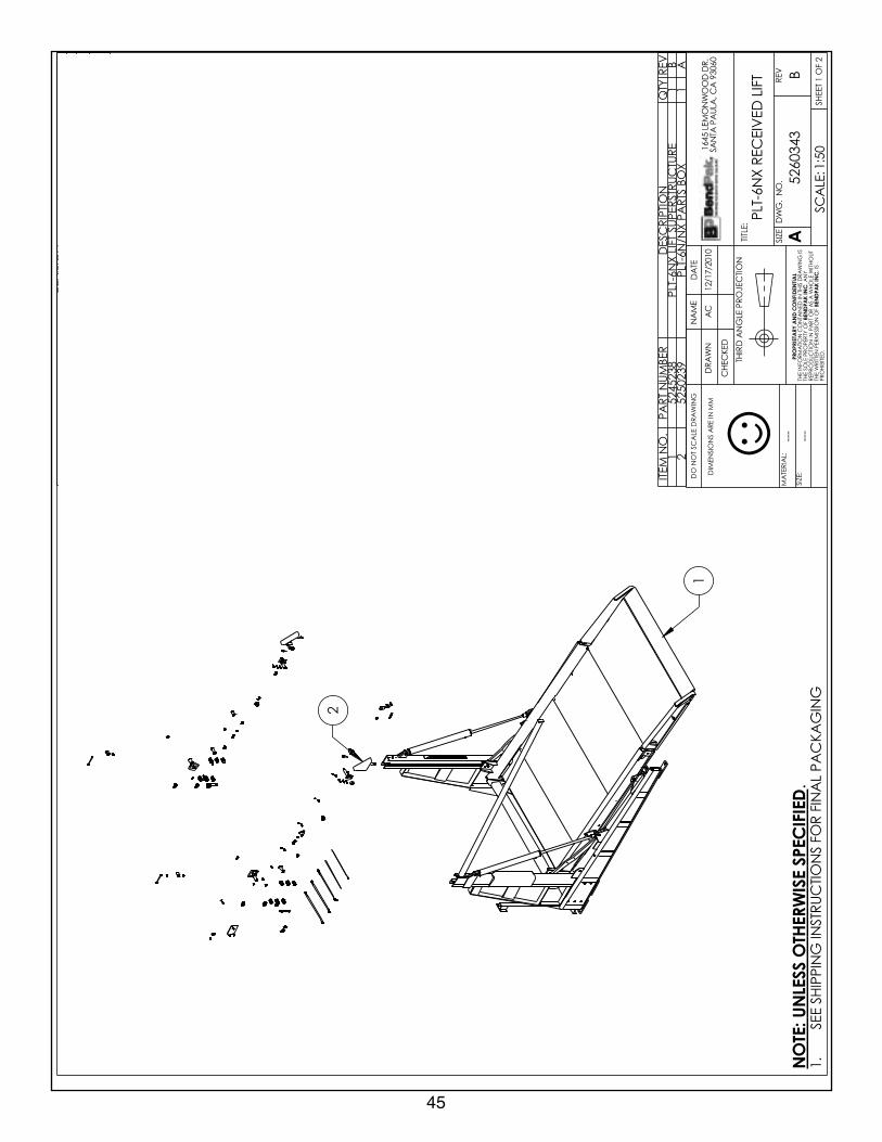
B0430625
TFIL DE
VIECER S6-TLP
GNI
GAK
CA P L
ANIF R
OF SN
OITCURTS
NI G
NIPPIHS EES.1
DEIFICEPS
ESIWREHT
OSSELNU:ET
ON
☺L
AITNEDIF
NO
CD
NA
YRATEIRP
ORP
.C
NIK
APDNEB
.CNI
KAPD
NEB
NOISIVER
.VERN
OITPIRCSE
DET
AD
YB DETI
DE#
OCE
AES
AELER N
OITCU
DORP
0102/71/21C
A62400
BS
NOISIVER
MOB
DETA
DP U1102/21/90
MT57400
.O
N METI
REBMU
N TRA P
NOITPIR
CSED
YTQ
VER1
532542 5ERUT
CURTSREPUS TFIL S6-TLP1
A2
832052 5X
OB STRAP XS/S6-TLP
1A
--- ---

43
2
1
.A
MM
NI ERA S
NOIS
NEMI
D :EZIS
:LAIRET
AM
GNI
WAR
D ELA
CS TO
N O
D
SI
GNI
WARD SIHT
NI DE
NIATN
OC
NOITA
MROF
NI EHT F
O YTREPORP EL
OS EHT Y
NA
TUOHTI
W ELOH
W A SA RO TRAP
NI N
OITCU
DORPER
FO
NOISSI
MREP NETTIR
W EHT SI
.DETIBIH
ORP05:1 :EL
ACS
2 FO 1 TEEHS
VER.
ON .
GW
DEZIS
:ELTIT
EM
AN
ETA
D
DEKCEH
C
NW
ARD
.RD
DO
OW
NO
MEL 546106039
AC ,
ALUAP
ATN
ASC
A0102/71/21
NOIT
CEJORP EL
GN
A DRIHT
B1430625
TFIL DE
VIECER XS6-TLP
GNI
GAK
CAP L
ANIF R
OF SN
OITCURTS
NI G
NIPPIHS EES.1
DEIFICEPS
ESIWREHT
OSSELNU:ET
ON
☺L
AITNEDIF
NO
CD
NA
YRATEIRP
ORP
.C
NIK
APDNEB
.CNI
KAPD
NEB
NOISIVER
.VERN
OITPIRCSE
DET
AD
YB DETI
DE#
OCE
AES
AELER N
OITCU
DORP
0102/71/21C
A62400
BS
NOISIVER
MOB
DETA
DP U1102/41/90
MT57400
.O
N METI
REBMU
N TRA P
NOITPIR
CSED
YTQ
VER1
632542 5ERUT
CURTSREPUS TFIL XS6-TLP1
B2
832052 5X
OB STRAP XS/S6-TLP
1A
--- ---

44
1
2
.A
MM
NI ERA S
NOIS
NEMI
D :EZIS
:LAIRET
AM
GNI
WAR
D ELA
CS TO
N O
D
SI
GNI
WARD SIHT
NI DE
NIATN
OC
NOITA
MROF
NI EHT F
O YTREPORP EL
OS EHT Y
NA
TUOHTI
W ELOH
W A SA RO TRAP
NI N
OITCU
DORPER
FO
NOISSI
MREP NETTIR
W EHT SI
.DETIBIH
ORP05:1 :EL
ACS
2 FO 1 TEEHS
VER.
ON .
GW
DEZIS
:ELTIT
EM
AN
ETA
D
DEKCEH
C
NW
ARD
.RD
DO
OW
NO
MEL 546106039
AC ,
ALUAP
ATN
ASC
A0102/71/21
NOIT
CEJORP EL
GN
A DRIHT
B2430625
TFIL DE
VIECER
N6-TLP
GNI
GAK
CA P L
ANIF R
OF SN
OITCURTS
NI G
NIPPIHS EES.1
DEIFICEPS
ESIWREHT
OSSELNU:ET
ON
☺L
AITNEDIF
NO
CD
NA
YRATEIRP
ORP
.C
NIK
APDNEB
.CNI
KAPD
NEB
NOISIVER
VERN
OITPIRCSE
DET
AD
YB DETI
DE#
OCE
AES
AELER N
OITCU
DORP
0102/71/21C
A62400
B
DETA
DPU ,9320525 HTIW 8320525
DEC
ALPERN
OISIVER M
OB1102/31/90
MT57400
.O
N METI
REBMU
N TRA P
NOITPIR
CSED
YTQ
VER1
732542 5ERUT
CURTSREPUS TFIL N6-TLP
1B
2932052 5
XOB STR
AP XN/
N6-TLP1
A
--- ---
45
2
1
.A
MM
NI ERA S
NOIS
NEMI
D :EZIS
:LAIRET
AM
GNI
WAR
D ELA
CS TO
N O
D
SI
GNI
WARD SIHT
NI DE
NIATN
OC
NOITA
MROF
NI EHT F
O YTREPORP EL
OS EHT Y
NA
TUOHTI
W ELOH
W A SA RO TRAP
NI N
OITCU
DORPER
FO
NOISSI
MREP NETTIR
W EHT SI
.DETIBIH
ORP05:1 :EL
ACS
2 FO 1 TEEHS
VER.
ON .
GW
DEZIS
:ELTIT
EM
AN
ETA
D
DEKCEH
C
NW
ARD
.RD
DO
OW
NO
MEL 546106039
AC ,
ALUAP
ATN
ASC
A0102/71/21
NOIT
CEJORP EL
GN
A DRIHT
B3430625
TFIL DE
VIECER X
N6-TLP
GNI
GAK
CAP L
ANIF R
OF SN
OITCURTS
NI G
NIPPIHS EES.1
DEIFICEPS
ESIWREHT
OSSELNU:ET
ON
☺L
AITNEDIF
NO
CD
NA
YRATEIRP
ORP
.C
NIK
APDNEB
.CNI
KAPD
NEB
NOISIVER
.VERN
OITPIRCSE
DET
AD
YB DETI
DE#
OCE
AES
AELER N
OITCU
DORP
0102/71/21C
A62400
B
DETA
DPU ,9320525 HTIW 8320525
DEC
ALPERN
OISIVER M
OB1102/31/90
MT57400
.O
N METI
REBMU
N TRAP
NOITPIR
CSED
YTQ
VER1
832542 5ERUT
CURTSREPUS TFIL XN6-TLP
1B
2932052 5
XOB STR
AP XN/
N6-TLP1
A
--- ---

46
2
1
.A
MM
NI ERA S
NOIS
NEMI
D :EZIS
:LAIRET
AM
GNI
WAR
D ELA
CS TO
N O
D
SI
GNI
WARD SIHT
NI DE
NIATN
OC
NOITA
MROF
NI EHT F
O YTREPORP EL
OS EHT Y
NA
TUOHTI
W ELOH
W A SA RO TRAP
NI N
OITCU
DORPER
FO
NOISSI
MREP NETTIR
W EHT SI
.DETIBIH
ORP05:1 :EL
ACS
2 FO 1 TEEHS
VER.
ON .
GW
DEZIS
:ELTIT
EM
AN
ETA
D
DEKCEH
C
NW
ARD
.RD
DO
OW
NO
MEL 546106039
AC ,
ALUAP
ATN
ASC
A0102/71/21
NOIT
CEJORP EL
GN
A DRIHT
B4430625
TFIL DEVIE
CER W6-TLP
GNI
GAK
CA P L
ANIF R
OF SN
OITCURTS
NI G
NIPPIHS EES.1
DEIFICEPS
ESIWREHT
OSSELNU:ET
ON
☺L
AITNEDIF
NO
CD
NA
YRATEIRP
ORP
.C
NIK
APDNEB
.CNI
KAPD
NEB
NOISIVER
.VERN
OITPIRCSE
DET
AD
YB DETI
DE#
OCE
AES
AELER N
OITCU
DORP
0102/71/21C
A62400
B
DETA
DPU ,0420525 HTIW 8320525
DEC
ALPERN
OISIVER M
OB1102/31/90
MT57400
.O
N METI
REBMU
N TRAP
NOITPIR
CSED
YTQ
VER1
9325425ERUT
CURTSREPUS TFIL W6-TL P
1B
2042052 5
XOB STR
AP XW/
W6-TLP1
A
--- ---

47
2
1
.A
MM
NI ERA S
NOIS
NEMI
D :EZIS
:LAIRET
AM
GNI
WAR
D ELA
CS TO
N O
D
SI
GNI
WARD SIHT
NI DE
NIATN
OC
NOITA
MROF
NI EHT F
O YTREPORP EL
OS EHT Y
NA
TUOHTI
W ELOH
W A SA RO TRAP
NI N
OITCU
DORPER
FO
NOISSI
MREP NETTIR
W EHT SI
.DETIBIH
ORP05:1 :EL
ACS
2 FO 1 TEEHS
VER.
ON .
GW
DEZIS
:ELTIT
EM
AN
ETA
D
DEKCEH
C
NW
ARD
.RD
DO
OW
NO
MEL 546106039
AC ,
ALUAP
ATN
ASC
A0102/71/21
NOIT
CEJORP EL
GN
A DRIHT
B5430625
TFIL DE
VIECER X
W6-TLP
GNI
GAK
CAP L
ANIF R
OF SN
OITCURTS
NI G
NIPPIHS EES.1
DEIFICEPS
ESIWREHT
OSSELNU:ET
ON
☺L
AITNEDIF
NO
CD
NA
YRATEIRP
ORP
.C
NIK
APDNEB
.CNI
KAPD
NEB
NOISIVER
.VERN
OITPIRCSE
DET
AD
YB DETI
DE#
OCE
AES
AELER N
OITCU
DORP
0102/71/21C
A62400
B
DETA
DPU ,0420525 HTIW 8320525
DEC
ALPERN
OISIVER M
OB1102/31/90
MT57400
.O
N METI
REBMU
N TRAP
NOITPIR
CSED
YTQ
VER1
042542 5ERUT
CURTSREPUS TFIL XW6-TLP
1B
2042052 5
XOB STR
AP XW/
W6-TLP1
A
--- ---

48
5
22
2
1
01
91
312
811
71
7
9
21
6
481
31
0251
41
3261
42
.A
MM
NI ERA S
NOIS
NEMI
D :EZIS
:LAIRET
AM
GNI
WAR
D ELA
CS TO
N O
D
SI
GNI
WARD SIHT
NI DE
NIATN
OC
NOITA
MROF
NI EHT F
O YTREPORP EL
OS EHT Y
NA
TUOHTI
W ELOH
W A SA RO TRAP
NI N
OITCU
DORPER
FO
NOISSI
MREP NETTIR
W EHT SI
.DETIBIH
ORP04:1 :EL
ACS
1 FO 1 TEEHS
VER.
ON .
GW
DEZIS
:ELTIT
EM
AN
ETA
D
DEKCEH
C
NW
ARD
.RD
DO
OW
NO
MEL 546106039
AC ,
ALUAP
ATN
ASC
A0102/01/21
NOIT
CEJORP EL
GN
A DRIHT
A5325425
T FIL S6-TLPERUT
CURTSREPUS
GNI
GAK
CAP L
ANIF R
OF SN
OITCURTS
NI G
NIPPIHS EES.1
DEIFICEPS
ESIWREHT
OSSELNU:ET
ON
☺L
AITNEDIF
NO
CD
NA
YRATEIRP
ORP
.C
NIK
APDNEB
.CNI
KAPD
NEB
NOISIVER
VERN
OITPIRCSE
DET
AD
YB DETI
DE#
OCE
AES
AELER N
OITCU
DORP
0102/01/21MT
62400B
SN
OISIVER M
OB DET
ADPU ,7150065
DED
DA
1102/21/90MT
57400
YLBMESS
A TXEN
0430625
ON
METIREB
MUN TR
APN
OITPIRCSE
DYT
QVER
15450065
HR TNE
MDLE
W TSOP SEIR ES 6-TLP
1B
2245006 5
HR TNE
MDLE
W MR
A TFIL SEIRES 6-TLP1
B3
635006 5T
NEM
DLEW R
AB RELLOR SEIRES S6-TLP
1B
47350065
HR TNE
MDLE
W LEN
NAH
C PM
AR SEIRES 6-TLP1
B5
175006 5T
NEM
DLEW P
MAR SEIRES S6-TLP
1A
6275006 5
TNE
MDLE
W RAB P
OTS ERIT SEIRES S6-TLP1
A7
445006 5HL T
NEM
DLEW TS
OP SEIRES 6-TLP1
B8
345006 5HL T
NEM
DLEW
MRA TFIL SEIRES 6-TLP
1B
9835006 5
HL TNE
MDLE
W LEN
NAH
C PM
AR SEIRES 6-TLP1
A01
935006 5HR T
NEM
DLEW
GEL SEIRES 6-TLP1
B11
045006 5HL T
NEM
DLEW
GEL SEIRES 6-TLP1
B21
145006 5T
NEM
DLEW LE
NN
AHC ES
OH SEIRES S6-TLP1
A31
543107 5MR
A G
NILEVEL SEIRES 6-TLP2
A41
645006 5T
NEM
DLEW LE
NN
AHC K
CED SEIRES S6-TLP
4A
51443107 5
ETALP K
CED SEIRES 6-TLP
2A
61455006 5
TNE
MDLE
W YTEFAS SEIRES S6-TLP
1B
713750065
D
NE D
OR RED
NILYC 57.2
Ø SEIRES 6-TLPR
OTCE
NN
OC
2B
810932055
"13.12 x 5.2Ø YLB
MESSA RE
DNILY
C2
B91
461617 5RE
DILS PM
AR SEIRES 6-TLP2
B02
561617 5RELL
OR TSOP SEIRES 6-TLP
2A
12743107 5
PARTS R
AB YTEFAS SEIRES 6-TLP
2B
22765006 5
PM
AR PU EVIRD SEIRES S6-TLP
1B
32075006 5
TNE
MDLE
W MR
A LORT
NO
C SEIRES 6-TLP1
B42
715006 5T
NEM
DLEW TS
OP TINU RE
WOP SEIRES 6-LP
1A
--- ---

49
5
22
2
1
01
61
312
811
42
9
21
6
4
71
31
4151
32
81
7
91
02
.A
MM
NI ERA S
NOIS
NEMI
D :EZIS
:LAIRET
AM
GNI
WAR
D ELA
CS TO
N O
D
SI
GNI
WARD SIHT
NI DE
NIATN
OC
NOITA
MROF
NI EHT F
O YTREPORP EL
OS EHT Y
NA
TUOHTI
W ELOH
W A SA RO TRAP
NI N
OITCU
DORPER
FO
NOISSI
MREP NETTIR
W EHT SI
.DETIBIH
ORP04:1 :EL
ACS
1 FO 1 TEEHS
VER.
ON .
GW
DEZIS
:ELTIT
EM
AN
ETA
D
DEKCEH
C
NW
ARD
.RD
DO
OW
NO
MEL 546106039
AC ,
ALUAP
ATN
ASC
A0102/71/21
NOIT
CEJORP EL
GN
A DRIHT
B6325425
TFIL XS6-TLPERUT
CURTSREPUS
GNI
GAK
CAP L
ANI F R
OF SN
OITCURTS
NI G
NIPPIHS EES.1
DEIFICEPS
ESIWREHT
OSSELNU:ET
ON
☺L
AITNEDIF
NO
CD
NA
YRATEIRP
ORP
.C
NIK
APDNEB
.CNI
KAPD
NEB
NOISIVER
VERN
OITPIRCSE
DET
AD
YB DETI
DE#
OCE
AES
AELER N
OITCU
DOR P
0102/01/21C
A62400
BS
NOISIVER
MOB
DETA
DPU ,7150065 DE
DD
A1102/21/90
MT57400
YLBMESS
A TXEN
1430625
ON
METIREB
MUN TR
A PN
OITPIRCSE
DYT
QVER
1235006 5
HR TNE
MDLE
W TSOP SEIRES X6-TLP
1B
2435006 5
HR TNE
MDLE
W MR
A TFIL SEIRES X6-TLP1
A3
635006 5T
NEM
DLEW R
AB RELLOR SEIRES S6-TLP
1B
47350065
HR TN E
MDLE
W LEN
NAH
C PM
AR SEIRES 6-TLP1
B5
175006 5T
NEM
DLEW P
MAR SEIRES S6-TLP
1A
6275006 5
TNE
MDLE
W RAB P
OTS ERIT SEIRES S6-TLP1
A7
335006 5HL T
NEM
DLEW TS
OP SEIRES X6-TLP1
B8
535006 5HL T
NEM
DLEW
MRA TFIL SEIRES X6-TLP
1B
9835006 5
HL TNE
MDLE
W LEN
NAH
C PM
AR SEIRES 6-TLP1
A01
935006 5HR T
NEM
DLEW
GEL SEIRES 6-TLP1
B11
045006 5HL T
NEM
DLEW
GEL SEIRES 6-TLP1
B21
145006 5T
NEM
DLEW LE
NN
AHC ES
OH SEIRES S6-TLP1
A31
2431075R
AB G
NILEVEL SE IRES X6-TLP2
A41
645006 5T
NEM
DLEW LE
NN
AHC K
CED SEIRES S6-TLP
4A
51443107 5
ETALP K
CED SEIRES 6-TLP
2A
61455006 5
TNE
MDLE
W YTEFAS SEIRES S6-TLP
1B
71083205 5
"86.82 x 5.2Ø YLB
MESSA RE
DNILY
C2
B81
3750065
DNE
DOR RE
DNILY
C 57.2Ø SEIRES 6-TLP
ROT
CEN
NO
C2
B91
4616175RE
DILS PM
AR SEIRES 6-TLP2
B02
561617 5RELL
OR TSOP SEIRES 6-TLP
2A
127431075
PARTS R
AB YTEFAS S EIRES 6-TLP
2B
22765006 5
PM
AR PU EVIRD SEIRES S6-TLP
1B
32075006 5
TNE
MDLE
W MR
A LORT
NO
C SEIRES 6-TLP1
B42
715006 5T
NEM
DLEW TS
OP TINU RE
WOP SEIRES 6-LP
1A
--- ---

50
5
22
2
1
01
6191
312
881
7
9
21
6
471
31
02 41
51
32
42
11
.A
MM
NI ERA S
NOIS
NEMI
D :EZIS
:LAIRET
AM
GNI
WAR
D ELA
CS TO
N O
D
SI
GNI
WARD SIHT
NI DE
NIATN
OC
NOITA
MROF
NI EHT F
O YTREPORP EL
OS EHT Y
NA
TUOHTI
W ELOH
W A SA RO TRAP
NI N
OITCU
DORPER
FO
NOISSI
MREP NETTIR
W EHT SI
.DETIBIH
ORP04:1 :EL
ACS
1 FO 1 TEEHS
VER.
ON .
GW
DEZIS
:ELTIT
EM
AN
ETA
D
DEKCEH
C
NW
ARD
.RD
DO
OW
NO
MEL 546106039
AC ,
ALUAP
ATN
ASC
A0102/01/21
NOIT
CEJORP EL
GN
A DRIHT
B7325425
TFIL N6-TLP
ERUTCURTSREPUS
GNI
GAK
CAP L
ANIF R
OF SN
OITCURTS
NI G
NIPPIHS EES.1
DEIFICEPS
ESIWREHT
OSSELNU:ET
ON
☺L
AITNEDIF
NO
CD
NA
YRATEIRP
ORP
.C
NIK
APDNEB
.CNI
KAPD
NEB
NOISIVER
VERN
OITPIRCSE
DET
AD
YB DETI
DE#
OCE
AES
AELER N
OITCU
DORP
0102/01/21MT
62400B
SN
OISIVER M
OB DET
ADPU ,7150065
DED
DA
1102/31/90MT
57400
YLBM ESS
A TXEN
2430625
ON
METIREB
MUN TR
APN
OITPIRCSE
DYT
QVER
15450065
HR TNE
MDLE
W TSOP SEIR ES 6-TLP
1B
2245006 5
HR TNE
MDLE
W MR
A TFIL SEIRES 6-TLP1
B3
655006 5T
NEM
DLEW R
AB RELLOR SEIRES
N6-TLP1
B4
7350065HR T
NEM
DLEW LE
NN
AHC P
MAR SEIRES 6-TLP
1B
5755006 5
TNE
MDLE
W PM
AR N6-TLP
1A
69550065
TNE
MDLE
W RAB P
OTS ERIT SEIRES N6-TLP
1A
7445006 5
HL TNE
MDLE
W TSOP SEIRES 6-TLP
1B
8345006 5
HL TNE
MDLE
W MR
A TFIL SEIRES 6-TLP1
B9
835006 5HL T
NEM
DLEW LE
NN
AHC P
MAR SEIRES 6-TLP
1A
01935006 5
HR TNE
MDLE
W GEL SEIRES 6-TLP
1B
11045006 5
HL TNE
MDLE
W GEL SEIRES 6-TLP
1B
21555006 5
TNE
MDLE
W LEN
NAH
C ESOH
N6-TLP1
A31
543107 5MR
A G
NILEVEL SEIRES 6-TLP2
A41
855006 5T
NEM
DLEW LE
NN
AHC K
CED SEIRES
N6-TLP4
A51
053107 5ET
ALP KCE
D SEIRES N6-TLP
2A
61065006 5
TNE
MDLE
W YTEFAS SEIRES
N6-TLP1
B71
093205 5"13.12 x 5.2
Ø YLBMESS
A RED
NILYC
2B
813750065
D
NE D
OR RED
NILYC 57.2
Ø SEIRES 6-TLPR
OTCE
NN
OC
2B
914616175
REDILS P
MAR SEIRES 6-TLP
2B
02561617 5
RELLOR TS
OP SEIRES 6-TLP2
A12
743107 5P
ARTS RAB YTEF
AS SEIRES 6-TLP2
B22
865006 5P
MAR PU EVIR
D SEIRES N6-TLP
1B
32075006 5
TNE
MDLE
W MR
A LORT
NO
C SEIRES 6-TLP1
B42
715006 5T
NEM
DLEW TS
OP TINU RE
WOP SEIRES 6-LP
1A
--- ---

51
5
22
2
1
01
61
91
312
8
7
921
64
71
31
02
4151
32
11
81
42
.A
MM
NI ERA S
NOIS
NEMI
D :EZIS
:LAIRET
AM
GNI
WAR
D ELA
CS TO
N O
D
SI
GNI
WARD SIHT
NI DE
NIATN
OC
NOITA
MROF
NI EHT F
O YTREPORP EL
OS EHT Y
NA
TUOHTI
W ELOH
W A SA RO TRAP
NI N
OITCU
DORPER
FO
NOISSI
MREP NETTIR
W EHT SI
.DETIBIH
ORP04:1 :EL
ACS
1 FO 1 TEEHS
VER.
ON .
GW
DEZIS
:ELTIT
EM
AN
ETA
D
DEKCEH
C
NW
ARD
.RD
DO
OW
NO
MEL 546106039
AC ,
ALUAP
ATN
ASC
A0102/71/21
NOIT
CEJORP EL
GN
A DRIHT
B8325425
TFI L XN6-TLP
ERUTCURTSREPUS
GNI
GAK
CAP L
ANI F R
OF SN
OITCURTS
NI G
NIPPIHS EES.1
DEIFICEPS
ESIWREHT
OSSELNU:ET
ON
☺L
AITNEDIF
NO
CD
NA
YRATEIRP
ORP
.C
NIK
APDNEB
.CNI
KAPD
NEB
NOISIVER
VERN
OITPIRCSE
DET
AD
YB DETI
DE#
OCE
AES
AELER N
OITCU
DOR P
0102/01/21C
A62400
BS
NOISIVER
MOB
DETA
DPU ,7150065 DE
DD
A1102/31/90
MT57400
YLBMESS
A TXEN
3430625
ON
METIREB
MUN TR
A PN
OITPIRCSE
DYT
QVER
1235006 5
HR TNE
MDLE
W TSOP SEIRES X6-TLP
1B
2435006 5
HR TNE
MDLE
W MR
A TFIL SEIRES X6-TLP1
A3
655006 5T
NEM
DLEW R
AB RELLOR SEIRES
N6-TLP1
B4
7350065HR T
NEM
DLEW LE
NN
AHC P
MAR SEIRES 6-TLP
1B
5755006 5
TNE
MDLE
W PM
AR N6-TLP
1A
69550065
TNE
MDLE
W RAB P
OTS ERIT SEIRES N6-TLP
1A
7335006 5
HL TNE
MDLE
W TSOP SEIRES X6-TLP
1B
8535006 5
HL TNE
MDLE
W MR
A TFIL SEIRES X6-TLP1
B9
835006 5HL T
NEM
DLEW LE
NN
AHC P
MAR SEIRES 6-TLP
1A
01935006 5
HR TNE
MDLE
W GEL SEIRES 6-TLP
1B
11045006 5
HL TNE
MDLE
W GEL SEIRES 6-TLP
1B
21555006 5
TNE
MDLE
W LEN
NAH
C ESOH
N6-TLP1
A31
2431075R
AB G
NILEVEL SEIRES X6-TLP2
A41
855006 5T
NEM
DLEW LE
NN
AHC K
CED SEIRES
N6-TLP4
A51
053107 5ET
ALP KCE
D SEIRES N6-TLP
2A
61065006 5
TNE
MDLE
W YTEFAS SEIRES
N6-TLP1
B71
083205 5"86.82 x 5.2
Ø YLBMESS
A RED
NILYC
2B
813750065
D
NE D
OR RED
NILYC 57.2
Ø SEIRES 6-TLPR
OTCE
NN
OC
2B
914616175
REDILS P
MAR SEIRES 6-TLP
2B
02561617 5
RELLOR TS
OP SEIRES 6-TLP2
A12
743107 5P
ARTS RAB YTEF
AS SEIRES 6-TLP2
B22
865006 5P
MAR PU EVIR
D SEIRES N6-TLP
1B
32075006 5
TNE
MDLE
W MR
A LORT
NO
C SEIRES 6-TLP1
B42
715006 5T
NEM
DLEW TS
OP TINU RE
WOP SEIRES 6-LP
1A
--- ---

52
5
22
2
1
01
6191
312
811
81
7
9
216
471
31
02
41
51 32
42
.A
MM
NI ERA S
NOIS
NEMI
D :EZIS
:LAIRET
AM
GNI
WAR
D ELA
CS TO
N O
D
SI
GNI
WARD SIHT
NI DE
NIATN
OC
NOITA
MROF
NI EHT F
O YTREPORP EL
OS EHT Y
NA
TUOHTI
W ELOH
W A SA RO TRAP
NI N
OITCU
DORPER
FO
NOISSI
MREP NETTIR
W EHT SI
.DETIBIH
ORP04:1 :EL
ACS
1 FO 1 TEEHS
VER.
ON .
GW
DEZIS
:ELTIT
EM
AN
ETA
D
DEKCEH
C
NW
ARD
.RD
DO
OW
NO
MEL 546106039
AC ,
ALUAP
ATN
ASC
A0102/01/21
NOIT
CEJORP EL
GN
A DRIHT
B9325425
TFIL W6-TLP
ERUTCURTSREPUS
GNI
GAK
CAP L
ANIF R
OF SN
OITCURTS
NI G
NIPPIHS EES.1
DEIFICEPS
ESIWREHT
OSSELNU:ET
ON
☺L
AITNEDIF
NO
CD
NA
YRATEIRP
ORP
.C
NIK
APDNEB
.CNI
KAPD
NEB
NOISIVER
VERN
OITPIRCSE
DET
AD
YB DETI
DE#
OCE
AES
AELER N
OITCU
DORP
0102/01/21MT
62400B
SN
OISIVER M
OB DET
ADPU ,7150065
DED
DA
1102/31/90'
MT57400
YLBMESS
A TXEN
4430625
ON
METIREB
MUN TR
APN
OITPIRCSE
DYT
QVER
15450065
HR TNE
MDLE
W TSOP SEIR ES 6-TLP
1B
2245006 5
HR TNE
MDLE
W MR
A TFIL SEIRES 6-TLP1
B3
365006 5T
NEM
DLEW R
AB RELLOR SEIRES
W6-TLP1
B4
7350065HR T
NEM
DLEW LE
NN
AHC P
MAR SEIRES 6-TLP
1B
5565006 5
TNE
MDLE
W PM
AR SEIRES W6-TLP
1A
6465006 5
TNE
MDLE
W RAB P
OTS ERIT SEIRES W6-TLP
1A
7445006 5
HL TNE
MDLE
W TSOP SEIRES 6-TLP
1B
8345006 5
HL TNE
MDLE
W MR
A TFIL SEIRES 6-TLP1
B9
835006 5HL T
NEM
DLEW LE
NN
AHC P
MAR SEIRES 6-TLP
1A
01935006 5
HR TNE
MDLE
W GEL SEIRES 6-TLP
1B
11045006 5
HL TNE
MDLE
W GEL SEIRES 6-TLP
1B
211650065
TNE
MDLE
W LEN
NAH
C ESOH SEIRE S
W6-TLP1
A31
543107 5MR
A G
NILEVEL SEIRES 6-TLP2
A41
265006 5T
NEM
DLEW LE
NN
AHC K
CED SEIRES
W6-TLP4
A51
253107 5ET
ALP KCE
D SEIRES W6-TLP
2A
61665006 5
TNE
MDLE
W YTEFAS SEIRES
W6-TLP1
B71
093205 5"13.12 x 5.2
Ø YLBMESS
A RED
NILYC
2B
813750065
D
NE D
OR RED
NILYC 57.2
Ø SEIRES 6-TLPR
OTCE
NN
OC
2B
914616175
REDILS P
MAR SEIRES 6-TLP
2B
02561617 5
RELLOR TS
OP SEIRES 6-TLP2
A12
743107 5P
ARTS RAB YTEF
AS SEIRES 6-TLP2
B22
965006 5P
MAR PU EVIR
D SEIRES W6-TLP
1B
32075006 5
TNE
MDLE
W MR
A LORT
NO
C SEIRES 6-TLP1
B42
715006 5T
NEM
DLEW TS
OP TINU RE
WOP SEIRES 6-LP
1A
--- ---
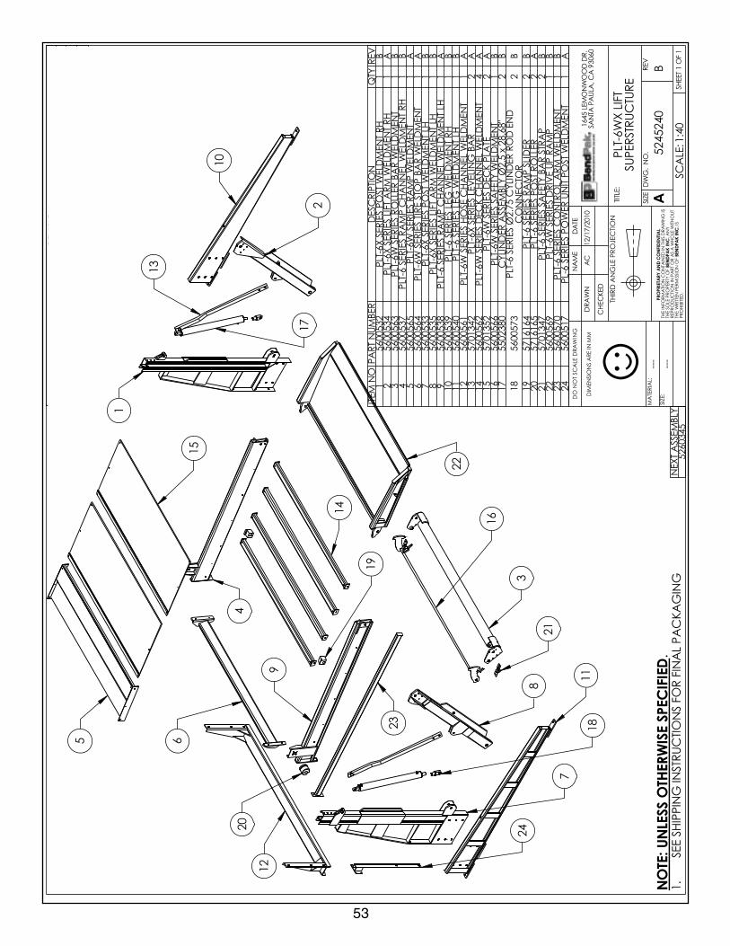
53
5
2
1
01
61
91
3
128
81
7
921
6
4
71
31
02
41
32
11
51
22
42
.A
MM
NI ERA S
NOIS
NEMI
D :EZIS
:LAIRET
AM
GNI
WAR
D ELA
CS TO
N O
D
SI
GNI
WARD SIHT
NI DE
NIATN
OC
NOITA
MROF
NI EHT F
O YTREPORP EL
OS EHT Y
NA
TUOHTI
W ELOH
W A SA RO TRAP
NI N
OITCU
DORPER
FO
NOISSI
MREP NETTIR
W EHT SI
.DETIBIH
ORP04:1 :EL
ACS
1 FO 1 TEEHS
VER.
ON .
GW
DEZIS
:ELTIT
EM
AN
ETA
D
DEKCEH
C
NW
ARD
.RD
DO
OW
NO
MEL 546106039
AC ,
ALUAP
ATN
ASC
A0102/71/21
NOIT
CEJORP EL
GN
A DRIHT
B0425425
TFIL XW6-TLP
ERUTCURTSREPUS
GNI
GAK
CAP L
ANIF R
OF SN
OITCURTS
NI G
NIPPIHS EES.1
DEIFICEPS
ESIWREHT
OSSELNU:ET
ON
☺L
AITNEDIF
NO
CD
NA
YRATEIRP
ORP
.C
NIK
APDNEB
.CNI
KAPD
NEB
NOISIVER
VERN
OITPIRCSE
DET
AD
YB DETI
DE#
OCE
AES
AELER N
OITCU
DOR P
0102/01/21C
A62400
BS
NOISIVER
MOB
DETA
DPU ,7150065 DE
DD
A1102/31/90
MT57400
YLBMESS
A TXEN
5430625
ON
METIREB
MUN TR
APN
OITPIRCSE
DYT
QVER
1235006 5
HR TNE
MDLE
W TSOP SEIRES X6-TLP
1B
2435006 5
HR TNE
MDLE
W MR
A TFIL SEIRES X6-TLP1
A3
365006 5T
NEM
DLEW R
AB RELLOR SEIRES
W6-TLP1
B4
7350065HR T
N EM
DLEW LE
NN
AHC P
MAR SEIRES 6-TLP
1B
5565006 5
TNE
MDLE
W PM
AR SEIRES W6-TLP
1A
6465006 5
TNE
MDLE
W RAB P
OTS ERIT SEIRES W6-TLP
1A
7335006 5
HL TNE
MDLE
W TSOP SEIRES X6-TLP
1B
8535006 5
HL TNE
MDLE
W MR
A TFIL SEIRES X6-TLP1
B9
835006 5HL T
NEM
DLEW LE
NN
AHC P
MAR SEIRES 6-TLP
1A
01935006 5
HR TNE
MDLE
W GEL SEIRES 6-TLP
1B
11045006 5
HL TNE
MDLE
W GEL SEIRES 6-TLP
1B
211650065
TNE
MDLE
W LEN
NAH
C ESOH SEIRES
W6-TLP1
A31
2431075R
AB G
NILEVEL SE IRES X6-TLP2
A41
265006 5T
NEM
DLEW LE
NN
AHC K
CED SEIRES
W6-TLP4
A51
253107 5ET
ALP KCE
D SEIRES W6-TLP
2A
61665006 5
TNE
MDLE
W YTEFAS SEIRES
W6-TLP1
B71
083205 5"86.82 x 5.2
Ø YLBMESS
A RED
NILYC
2B
813750065
D
NE D
OR RED
NILYC 57.2
Ø SEIRES 6-TLPR
OTCE
NN
OC
2B
914616175
REDILS P
MAR SEIRES 6-TLP
2B
02561617 5
RELLOR TS
OP SEIRES 6-TLP2
A12
7431075P
ARTS RAB YTEF
AS S EIRES 6-TLP2
B22
965006 5P
MAR PU EVIR
D SEIRES W6-TLP
1B
32075006 5
TNE
MDLE
W MR
A LORT
NO
C SEIRES 6-TLP1
B42
715006 5T
NEM
DLEW TS
OP TINU RE
WOP SEIRES 6-LP
1A
--- ---

54
CLIATED5:
1ELA
CS
31
ELIATED5:
1ELA
CS
2
FLIATED8:
1ELA
CS
98
DLIATED5:
1ELA
CS
501
BLIATED5:
1ELA
CS
7
ALIATED01:
1ELA
CS
6
1121
A
B
D
FE
C
1
4
351
41
81
6171
91
.
SD
mm1401 x 5 3.6
Ø YSSA ES
OH CILU
ARDYH SEIRES 6-TLP
SD
mm5091 x 53.6
Ø YSSA ES
OH CILU
ARDYH SEIRES 6-TLP
BS m
m3924 x 53.6Ø YSS
A ESOH
CILUAR
DYH XS/S6-TLP
A
MM
NI ERA S
NOIS
NEMI
D :EZIS
:LAIRET
AM
GNI
WAR
D ELA
CS TO
N O
D
SI
GNI
WARD SIHT
NI DE
NIATN
OC
NOITA
MROF
NI EHT F
O YTREPORP EL
OS EHT Y
NA
TUOHTI
W ELOH
W A SA RO TRAP
NI N
OITCU
DORPER
FO
NOISSI
MREP NETTIR
W EHT SI
.DETIBIH
ORP04:1 :EL
ACS
1 FO 1 TEEHS
VER.
ON .
GW
DEZIS
:ELTIT
EM
AN
ETA
D
DEKCEH
C
NW
ARD
.RD
DO
OW
NO
MEL 546106039
AC ,
ALUAP
ATN
ASC
A0102/71/21
NOIT
CEJORP EL
GN
A DRIHT
A8320525
XOB STR
AP XS/S6-TLP
GNI
GAK
CAP L
ANIF R
OF SN
OITCURTS
NI G
NIPPIH S EES.1
YLN
O EC
NEREFER ROF YT
Q 81 METI)*(
.2
DEIFICEPS
ESIWREHT
OSSELNU:ET
ON☺
LAIT
NEDIFN
OC
DN
AYR
ATEIRPORP
.C
NIK
APDNEB
.CNI
KAPD
NEB
NOISIVER
.VERN
OITPIRCSE
DET
AD
YB DETI
DE#
OCE
AES
AELER N
OITCU
DOR P
0102/02/21C
A62400
B
,4810755 ,2145955 ,5126475 ,0126475 DE
DD
A ,3005175 ,5970755 ,6810755 ,5810755
DE
CALPER ,4126475 ,3550065
DEVO
MER
MOB
DETA
DPU ,2550065 HTIW 8221375
EREHW T
CELFER OT ELTIT
D ETA
DPJU ,SN
OISIVERDESU
1102/21/90MT
57400
METI.
ON
TRAP
REBMU
NN
OITPIRCSE
D.YT
QVER
1036471 5
GAB STR
AP SEIRES 6-TLP1
B2
7030355"5 x "4/3 B
A4
-3
845006 5HL T
NEM
DLEW
DRAU
G ERIT SEIRES 6-TLP1
B4
945006 5HR T
NEM
DLEW
DRAU
G ERIT SEIRES 6-TLP1
B5
0550065T
NEM
DLEW
NIP KC
OLB EDILS P
MAR SEIRES 6-TLP
2B
6745006 5
TNE
MDLE
W NIP RELL
OR SEIRES 6-TLP2
A7
155006 5T
NEM
DLEW
NIP MR
A TFIL TSOP SEIRES 6-TLP
2A
82550065
TNE
MDLE
W MR
A YTEFAS SEIRES 6-TLP
1B
9661617 5
LEEHW YTEF
AS SEIRES 6-TLP1
A01
512647 5RE
CAPS K
COLB E
DILS SEIRES 6-TLP2
B11
9026475RE
CAPS
MRA SEIRES 6-TLP
2A
21001565 5
GNIR
AEB REC
APS MR
A NIP RELL
OR SEIRES 6-TLP4
A31
501565 5G
NIRAEB RE
CAPS
MRA TFIL SEIRES 6-TLP
2A
415970755
GNIBUT
OLF-YLOP "4/1
*m
m0058-
512145955
YLBMESS
A TIUD
NO
C EPOR ERI
W SEIRES 6-TLP1
A61
48107551
A71
68107551
A81
58107551
A91
300517 5RE
NEPM
AD
NOIT
ARBIV TINU RE
WOP
1B
YLBMESS
A TXEN
04306251430625
--- ---

55
DLIATED8:
1ELA
CS
718
5
CLIATED8:
1ELA
CS31
41
11
21
0392
1323
BLIATED6:
1ELA
CS
63
7
ALIATED21:
1ELA
CS
3212
2
42
152
81
A
B
C
D
61
51
02
22
82
62
72
33
73 6353
43
4
901
91
.
)6( ,8370355 )1( ,5720455 )6( ,3126475 ,2126475 DE
DD
A 4400555 ,3120355 ,0670355 ,9570355 ,1415355 ,3105355
3510555 1810555 9840555 4000555 1000255 0025455 ,0526475 ,1005355 )2( ,3000455 ,4126475 ,0126475
DEVO
MER ,5005455 ,2115355 ,1526475 ,01003551205455
A
MM
NI ERA S
NOIS
NEMI
D :EZIS
:LAIRET
AM
GNI
WAR
D ELA
CS TO
N O
D
SI
GNI
WARD SIHT
NI DE
NIATN
OC
NOITA
MROF
NI EHT F
O YTREPORP EL
OS EHT Y
NA
TUOHTI
W ELOH
W A SA RO TRAP
NI N
OITCU
DORPER
FO
NOISSI
MREP NETTIR
W EHT SI
.DETIBIH
ORP02:1 :EL
ACS
1 FO 1 TEEHS
VER.
ON .
GW
DEZIS
:ELTIT
EM
AN
ETA
D
DEKCEH
C
NW
ARD
.RD
DO
OW
NO
MEL 546106039
AC ,
ALUAP
ATN
ASMT
0102/31/21
NOIT
CEJORP EL
GN
A DRIHT
B0364715
GAB STR
AP SEIRES 6-TLP
GNI
GAK
CAP L
ANIF R
OF SN
OITCURTS
NI G
NIPPIHS EES.1
DEIFICEPS
ESIWREHT
OSSELNU:ET
ON
☺L
AITNEDIF
NO
CD
NA
YRATEIRP
ORP
.C
NIK
APDNEB
.CNI
KAPD
NEB
NOISIVER
VERN
OITPIRCSE
DET
AD
YB DETI
DE#
OCE
AES
AELER N
OITCU
DORP
0102/31/21MT
62400
B1102/90/90
MT57400
YLBMESS
A TXEN
832052563205250420525
ON
METIREB
MUN TR
APN
OITPIRCSE
DYT
QVER
1837035 5
52 x 5.1 x 01M BHH
73-
25720455
0520 9976 NI
D D
O m
m52Ø
GNIR E
61-
33105355
LN 5.1 x 01
M TUN
44-
47105355
LN 5.2 x 02
M TUN
81-
57535355
LN 0.1 x 6
M TUN
01-
61435455
TALF 02
Ø x 01M REHS
AW
83-
72030355
04 x 5.1 x 01M BHH
01-
86205455
LS 21Ø x 6
M REHSA
W01
-9
3435455T
ALF 02M ,REHS
AW
81-
014510355
54 x 5.2 x 02M BHH
81-
11202545 5
LS 51Ø x 8
M REHSA
W1
-21
141535 5NJ 5.1 x 01
M TUN
3-
31957035 5
05 x 5.1 x 01M BHH
1-
41067035 5
53x52.1x01M TL
OB D
AEH XEH1
-51
311535 5NJ 57.1 x 21
M TUN
2-
61141035 5
07 x 57.1 x 21M BHH
2-
71813035 5
mm52 x 1 x 6
M SPHP01
-81
6010555TP
N 60-CIJ 40- BLE
GTF2
-91
312647 5NIP SIVEL
C RED
NILYC SEIRES 6-TLP
2B
02212647 5
NIP PM
AR PU EVIRD SEIRES 6-TLP
2B
12312035 5
041 x 5.1 x 01M BHH
2-
22440055 5
BRO L40-
CIJ 40- BLE GTF
1-
32002545 5
LS 81Ø x 01
M REHSA
W3
-42
100025 5.
D.I 4/3 ,TEM
MOR
G REBBUR2
-52
400055 5TP
N 8/3 SNI EBUT 4/1 BLE
GTF3
-62
984055 5S
NI EBUT 4/1-4/1-4/1 EET GTF
1-
72181055 5
TPN 40 x
CIJ 40- x CIJ 40- EET
GTF1
-82
351055 5CIJ 40- x F TP
N 40- BLE GTF
1-
920126475
,REC
APS MR
A RELLOR YTEF
AS SEIRES 6-TLPG
NOL
1B
034125575
REC
APS MR
A RELLOR YTEF
AS SEIRES 6-TLP1
B13
300045 5m
m09 x m
m61Ø
GNIRPS
1A
23100535 5
LN 52.1 x 8
M TUN
5-
33052647 5
LA
NIMRET TIU
DN
OC ELB
AC SEIRES 6-TLP
2A
43010035 5
52 x 52.1 x 8M BHH
4-
53152647 5
TLOB YTEF
AS SEIRES 6-TLP1
A63
211535 50.1 x 6
M TUN
2-
73500545 5
REHSA
W TALF 6
M2
-
--- ---

56
BendPak Inc. / RangeR PRoducts1645 e. Lemonwood drive
santa Paula, ca 93060PH. (805) 933-9971 • FAX. (805) 933-9160
www.bendpak.com
For parts or service please call 1-800-253-2363
P/n: 5900175
© 2011 BendPak / Ranger Products are registered trademarks.