Embed Size (px)
Citation preview
Installation and Operating Data
H05
7350
0-
Installation and Operation Manual
WARNINGFOR YOUR SAFETY - This product must be installed and serviced by a professional pool/spa service technician. The procedures in this manual must be followed exactly. Failure to follow warning notices and instructions may result in property damage, serious injury, or death.
Water Purification SystemPower Center and Cell Kit
For use with

Page 3
Section 1. Safety Information ....................... 4
Section 2. System Description ...................... 52.1 ElectricalSpecifications ............... 6
Section 3. Installation Instructions Model PureLink AP700 and AP1400 ...... 8
3.1 Materials and Tools ...................... 83.2 PlumbingConfigurations ............. 8
3.2.1 Recommended Plumbing Configuration ....................... 8
3.2.2 Alternate Plumbing Configurations ..................... 9
3.3 Installing AquaLink RS PureLink Power Center ................................ 12
3.4 Earth Bonding (Grounding) ......... 133.5 Installing the APURE700 and
APURE1400 Cell and Flow/Temp/Salinity Sensor ............................. 14
3.6 Connection to the AquaLink® RS PureLink Control System ............. 16
Section 4. Pool Water Preparation ................ 174.1 Determining Pool Size
(m3 of Water) ................................ 174.2 Determining Pool Size (Gallons) . 174.3 Selecting Model Size ................... 184.4 Chemistry You Need to Know ..... 184.5 Optimum Pool Water Conditions 194.6 Chlorine Testing .......................... 194.7 Salt (NaCl sodium chloride) ....... 19
4.7.1 What Type of Salt to Use? ... 194.7.2 How Much Salt to Use? ....... 204.7.3 How to Add Salt to the Pool? 20
Section 5. Operating Instructions .................. 235.1 Using the Front Panel Controls .... 235.2 Reading the Display ..................... 245.3 Operation ...................................... 255.4 Startup .......................................... 26
5.4.1 Shocking .............................. 265.4.2 Apply Power ........................ 26
5.5 Operating in Winter ...................... 265.6 Recommendations ........................ 27
Section 6. User Maintenance Instructions .... 286.1 Daily ............................................. 286.2 Weekly ......................................... 286.3 Monthly ........................................ 286.4 Electrolytic Cell Cleaning ............ 286.5 Flow/Temp/Salinity Sensor
Cleaning ....................................... 296.6 Winterizing ................................... 30
Section 7. Troubleshooting ........................... 317.1 Problems and Corrective Action .. 317.2 Service Codes ............................... 347.3 Additional Letter Codes ............... 34
Section 8. Temperature Conversion .............. 35
Section 9. AP700 and AP1400 Exploded Views and Replacement Kits .................. 36
9.1 AquaLink RS PureLink Power Center ........................................... 36
9.2 2” PVC Union, Electrolytic Cell .. 379.3 PureLink Flow Sensor.................. 37
Table of Contents
Page �
WARNINGTo reduce the risk of electric shock, fire or injury, service should only be attempted by a qualified Pool Service Professional.
WARNINGWhen mixing acid with water, ALWAYS ADD ACID TO WATER. NEVER ADD WATER TO ACID.
WARNINGDo not operate electrolytic cell without proper flow or water circulation. A buildup of flammable gases would result in hazardous conditions.
WARNINGRISK OF ELECTRIC SHOCK, FIRE, PERSONAL INJURY, OR DEATH. Installation must be done in accordance with the National Electric Code (NEC, NFPA-70) and/or any other applicable local and national installation codes.A green colored terminal (or a wire connector marked “G”, “GR”, “Ground” or “Grounding”) is provided within the terminal compartment. To reduce risk of electric shock, connect this terminal or connector to the grounding terminal of your electric service or supply panel with a conductor equivalent in size to the circuit conductors supplying this equipment.Power supply must be interconnected with Pool Pump motor power source. This insures the chlorinator and pool pump will turn on and off together.Use of chemicals other than those recommended may be hazardous. Follow the Chemical Manufacturers Instructions.It is recommended that the water Flow/Temp/Salinity Sensor is installed in the same piping as the electrolytic cell, without any valves or diverters between them. (See Figure 1).The Flow/Temp/Salinity Sensor must be mounted as in Figure 12.
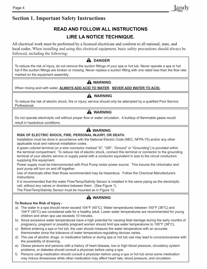
Section 1. Important Safety Instructions
READ AND FOLLOW ALL INSTRUCTIONSLIRE LA NOTICE TECHNIQUE.
All electrical work must be performed by a licensed electrician and conform to all national, state, and local codes. When installing and using this electrical equipment, basic safety precautions should always be followed, including the following:
DANGERTo reduce the risk of injury, do not remove the suction fittings of your spa or hot tub. Never operate a spa or hot tub if the suction fittings are broken or missing. Never replace a suction fitting with one rated less than the flow rate marked on the equipment assembly.
WARNINGTo Reduce the Risk of Injury -a) The water in a spa should never exceed 104°F (40°C). Water temperatures between 100°F (38°C) and
104°F (40°C) are considered safe for a healthy adult. Lower water temperatures are recommended for young children and when spa use exceeds 10 minutes.
b) Since excessive water temperatures have a high potential for causing fetal damage during the early months of pregnancy, pregnant or possibly pregnant women should limit spa water temperatures to 100°F (38°C).
c) Before entering a spa or hot tub, the user should measure the water temperature with an accurate thermometer since the tolerance of water temperature-regulating devices varies.
d) The use of alcohol, drugs, or medication before or during spa or hot tub use may lead to unconsciousness with the possibility of drowning.
e) Obese persons and persons with a history of heart disease, low or high blood pressure, circulatory system problems, or diabetes should consult a physician before using a spa.
f) Persons using medication should consult a physician before using a spa or hot tub since some medication may induce drowsiness while other medication may affect heart rate, blood pressure, and circulation.
Page 5
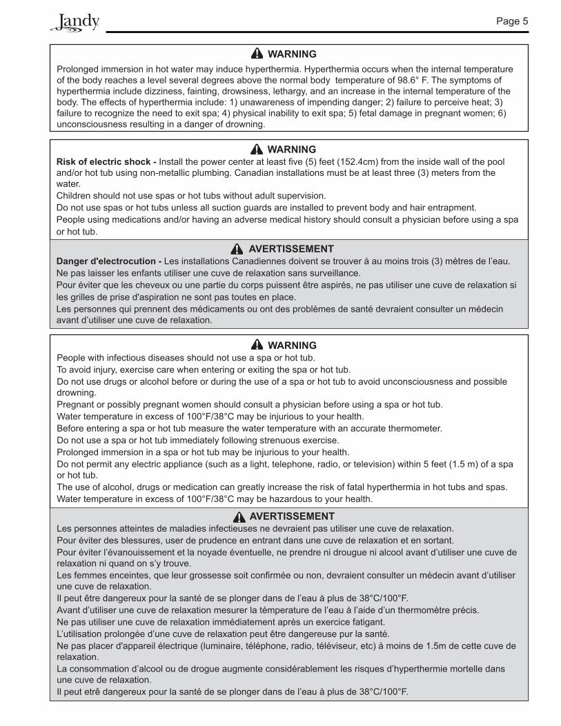
WARNINGProlonged immersion in hot water may induce hyperthermia. Hyperthermia occurs when the internal temperature of the body reaches a level several degrees above the normal body temperature of 98.6° F. The symptoms of hyperthermia include dizziness, fainting, drowsiness, lethargy, and an increase in the internal temperature of the body. The effects of hyperthermia include: 1) unawareness of impending danger; 2) failure to perceive heat; 3) failure to recognize the need to exit spa; 4) physical inability to exit spa; 5) fetal damage in pregnant women; 6) unconsciousness resulting in a danger of drowning.
WARNINGRisk of electric shock - Install the power center at least five (5) feet (152.4cm) from the inside wall of the pool and/or hot tub using non-metallic plumbing. Canadian installations must be at least three (3) meters from the water. Children should not use spas or hot tubs without adult supervision.Do not use spas or hot tubs unless all suction guards are installed to prevent body and hair entrapment.People using medications and/or having an adverse medical history should consult a physician before using a spa or hot tub.
AVERTISSEMENTDanger d'electrocution - Les installations Canadiennes doivent se trouver à au moins trois (3) mètres de l’eau.Ne pas laisser les enfants utiliser une cuve de relaxation sans surveillance.Pour éviter que les cheveux ou une partie du corps puissent être aspirés, ne pas utiliser une cuve de relaxation si les grilles de prise d'aspiration ne sont pas toutes en place.Les personnes qui prennent des médicaments ou ont des problèmes de santé devraient consulter un médecin avant d’utiliser une cuve de relaxation.
WARNINGPeople with infectious diseases should not use a spa or hot tub.To avoid injury, exercise care when entering or exiting the spa or hot tub.Do not use drugs or alcohol before or during the use of a spa or hot tub to avoid unconsciousness and possible drowning.Pregnant or possibly pregnant women should consult a physician before using a spa or hot tub. Water temperature in excess of 100°F/38°C may be injurious to your health. Before entering a spa or hot tub measure the water temperature with an accurate thermometer. Do not use a spa or hot tub immediately following strenuous exercise.Prolonged immersion in a spa or hot tub may be injurious to your health.Do not permit any electric appliance (such as a light, telephone, radio, or television) within 5 feet (1.5 m) of a spa or hot tub.The use of alcohol, drugs or medication can greatly increase the risk of fatal hyperthermia in hot tubs and spas.Water temperature in excess of 100°F/38°C may be hazardous to your health.
AVERTISSEMENTLes personnes atteintes de maladies infectieuses ne devraient pas utiliser une cuve de relaxation.Pour éviter des blessures, user de prudence en entrant dans une cuve de relaxation et en sortant.Pour éviter l’évanouissement et la noyade éventuelle, ne prendre ni drougue ni alcool avant d’utiliser une cuve de relaxation ni quand on s’y trouve.Les femmes enceintes, que leur grossesse soit confirmée ou non, devraient consulter un médecin avant d’utiliser une cuve de relaxation.Il peut être dangereux pour la santé de se plonger dans de l’eau à plus de 38°C/100°F.Avant d’utiliser une cuve de relaxation mesurer la témperature de l’eau à l’aide d’un thermomètre précis.Ne pas utiliser une cuve de relaxation immédiatement après un exercice fatigant.L’utilisation prolongée d’une cuve de relaxation peut être dangereuse pur la santé.Ne pas placer d'appareil électrique (luminaire, téléphone, radio, téléviseur, etc) à moins de 1.5m de cette cuve de relaxation.La consommation d’alcool ou de drogue augmente considérablement les risques d’hyperthermie mortelle dans une cuve de relaxation.Il peut etrê dangereux pour la santé de se plonger dans de l’eau à plus de 38°C/100°F.
Page 6
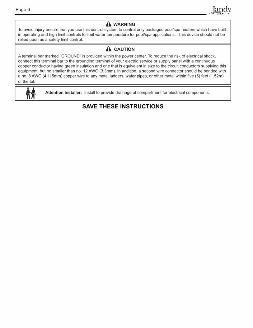
CAUTIONA terminal bar marked "GROUND" is provided within the power center. To reduce the risk of electrical shock, connect this terminal bar to the grounding terminal of your electric service or supply panel with a continuous copper conductor having green insulation and one that is equivalent in size to the circuit conductors supplying this equipment, but no smaller than no. 12 AWG (3.3mm). In addition, a second wire connector should be bonded with a no. 8 AWG (4.115mm) copper wire to any metal ladders, water pipes, or other metal within five (5) feet (1.52m) of the tub.
SAVE THESE INSTRUCTIONS
Attention installer: Install to provide drainage of compartment for electrical components.
WARNINGTo avoid injury ensure that you use this control system to control only packaged pool/spa heaters which have built-in operating and high limit controls to limit water temperature for pool/spa applications. This device should not be relied upon as a safety limit control.
Page 7
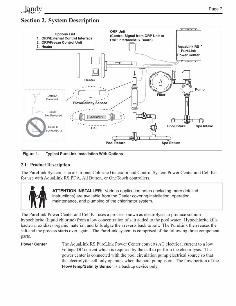
Section 2. System Description
2.1 Product Description
The PureLink System is an all-in-one, Chlorine Generator and Control System Power Center and Cell Kit for use with AquaLink RS PDA, All Button, or OneTouch controllers.
ATTENTION INSTALLER: Various application notes (including more detailed instructions) are available from the Dealer covering installation, operation, maintenance, and plumbing of the chlorinator system.
Figure 1. Typical PureLink Installation With Options
AquaPure
PumpFilter
AquaLink RS PureLink
Power Center
Flow/Salinity Sensor
Cell
Heater
Spa IntakePool Intake
Spa ReturnPool Return
Options List1. ORP/External Control Interface2. ORP/Freeze Control Unit3. Heater
ORP Unit(Control Signal from ORP Unit to ORP Interface/Aux Board)
The PureLink Power Center and Cell Kit uses a process known as electrolysis to produce sodium hypochlorite (liquid chlorine) from a low concentration of salt added to the pool water. Hypochlorite kills bacteria, oxidizes organic material, and kills algae then reverts back to salt. The PureLink then reuses the salt and the process starts over again. The PureLink system is comprised of the following three component parts.
Power Center The AquaLink RS PureLink Power Center converts AC electrical current to a low voltage DC current which is required by the cell to perform the electrolysis. The power center is connected with the pool circulation pump electrical source so that theelectrolyticcellonlyoperateswhenthepoolpumpison.TheflowportionoftheFlow/Temp/Salinity Sensor is a backup device only.
Detail A
Detail B
Detail C
Preferred
Not Preferred
Hazardous
Page 8
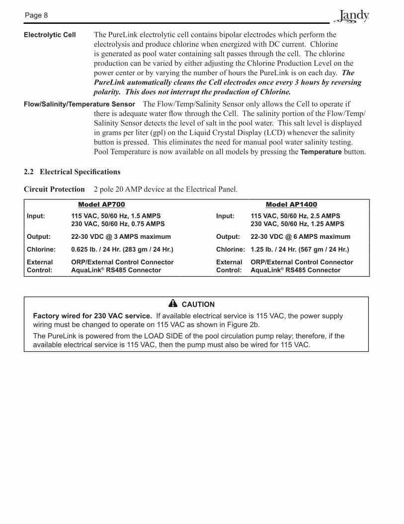
Electrolytic Cell The PureLink electrolytic cell contains bipolar electrodes which perform the electrolysis and produce chlorine when energized with DC current. Chlorine is generated as pool water containing salt passes through the cell. The chlorine production can be varied by either adjusting the Chlorine Production Level on the power center or by varying the number of hours the PureLink is on each day. The PureLink automatically cleans the Cell electrodes once every 3 hours by reversing polarity. This does not interrupt the production of Chlorine.
Flow/Salinity/Temperature Sensor The Flow/Temp/Salinity Sensor only allows the Cell to operate if thereisadequatewaterflowthroughtheCell.ThesalinityportionoftheFlow/Temp/Salinity Sensor detects the level of salt in the pool water. This salt level is displayed in grams per liter (gpl) on the Liquid Crystal Display (LCD) whenever the salinity button is pressed. This eliminates the need for manual pool water salinity testing. Pool Temperature is now available on all models by pressing the Temperature button.
2.2 ElectricalSpecifications
Circuit Protection 2 pole 20 AMP device at the Electrical Panel.
Model AP700 Model AP1400Input: 115 VAC, 50/60 Hz, 1.5 AMPS
230 VAC, 50/60 Hz, 0.75 AMPSInput: 115 VAC, 50/60 Hz, 2.5 AMPS
230 VAC, 50/60 Hz, 1.25 AMPS
Output: 22-30 VDC @ 3 AMPS maximum Output: 22-30 VDC @ 6 AMPS maximum
Chlorine: 0.625 lb. / 24 Hr. (283 gm / 24 Hr.) Chlorine: 1.25 lb. / 24 Hr. (567 gm / 24 Hr.)
External Control:
ORP/External Control ConnectorAquaLink® RS485 Connector
External Control:
ORP/External Control ConnectorAquaLink® RS485 Connector
CAUTIONFactory wired for 230 VAC service. If available electrical service is 115 VAC, the power supply wiring must be changed to operate on 115 VAC as shown in Figure 2b.The PureLink is powered from the LOAD SIDE of the pool circulation pump relay; therefore, if the available electrical service is 115 VAC, then the pump must also be wired for 115 VAC.
Page 9
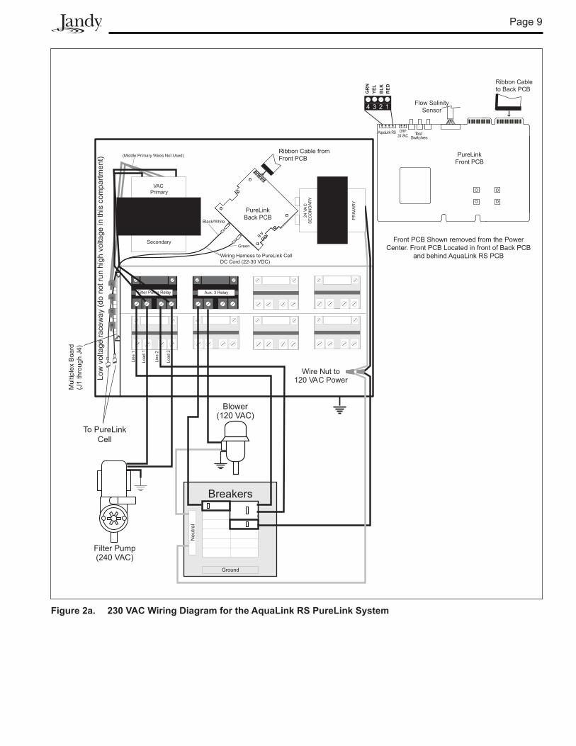
Figure 2a. 230 VAC Wiring Diagram for the AquaLink RS PureLink System
Filter Pump Relay Aux. 3 Relay
Load
2
Line
2
Load
1
Line
1
Wire Nut to120 VAC PowerLo
wvo
ltage
race
way
(do
notr
unhi
ghvo
lt age
inth
isco
mp a
rtmen
t)
Breakers
Ground
Neu
tral
Blower(120 VAC)
Filter Pump(240 VAC)
PR
IMA
RY
24VA
CS
EC
ON
DA
RY
VAC Primary
Secondary
A B
PureLinkBack PCB
Ribbon Cable from Front PCB
To PureLinkCell
TestSwitches
4 3 2 1
RED
BLK
YEL
GR
N
AquaLink RS ORP24 VAC
Flow SalinitySensor
Ribbon Cableto Back PCB
PureLinkFront PCB
Front PCB Shown removed from the Power Center. Front PCB Located in front of Back PCB
and behind AquaLink RS PCB
(Middle Primary Wires Not Used)
Wiring Harness to PureLink Cell DC Cord (22-30 VDC)
Green
Black/White
Mul
tiple
x B
oard
(J1
thro
ugh
J4)
J1J2
J3J4
Page 10
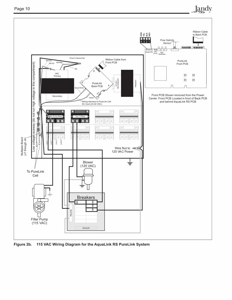
Figure 2b. 115 VAC Wiring Diagram for the AquaLink RS PureLink System
Filter Pump Relay Aux. 3 Relay
Load
2
Line
2
Load
1
Line
1
Wire Nut to120 VAC PowerLo
wvo
ltage
race
way
(do
notr
unhi
ghvo
lt age
inth
isco
mp a
rtmen
t)
Breakers
Ground
Neu
tral
Blower(120 VAC)
Filter Pump(115 VAC)
PR
IMA
RY
24VA
CS
EC
ON
DA
RY
VAC Primary
Secondary
A B
PureLinkBack PCB
Ribbon Cable from Front PCB
To PureLinkCell
TestSwitches
4 3 2 1
RED
BLK
YEL
GR
N
AquaLink RS ORP24 VAC
Flow SalinitySensor
Ribbon Cableto Back PCB
PureLinkFront PCB
Front PCB Shown removed from the Power Center. Front PCB Located in front of Back PCB
and behind AquaLink RS PCB
Wired to Neutral Bar
Wiring Harness to PureLink Cell DC Cord (22-30 VDC)
Green
Black/White
Mul
tiple
x B
oard
(J1
thro
ugh
J4)
J1J2
J3J4
Blk/WhtBlk/Yel Blk/Red
Blk
Page 11
Section 3. Installation Instructions Model PureLink AP700 and AP1400
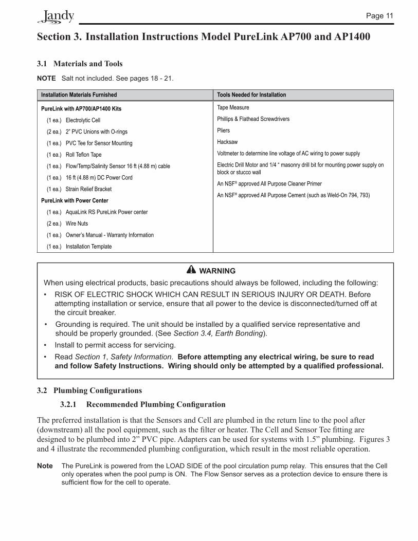
3.1 Materials and Tools
NOTE Salt not included. See pages 18 - 21.
Installation Materials Furnished Tools Needed for Installation
PureLink with AP700/AP1400 Kits
(1 ea.) Electrolytic Cell
(2 ea.) 2” PVC Unions with O-rings
(1 ea.) PVC Tee for Sensor Mounting
(1 ea.) Roll Teflon Tape
(1 ea.) Flow/Temp/Salinity Sensor 16 ft (4.88 m) cable
(1 ea.) 16 ft (4.88 m) DC Power Cord
(1 ea.) Strain Relief Bracket
PureLink with Power Center
(1 ea.) AquaLink RS PureLink Power center
(2 ea.) Wire Nuts
(1 ea.) Owner’s Manual - Warranty Information
(1 ea.) Installation Template
Tape Measure
Phillips & Flathead Screwdrivers
Pliers
Hacksaw
Voltmeter to determine line voltage of AC wiring to power supply
Electric Drill Motor and 1/4 “ masonry drill bit for mounting power supply on block or stucco wall
An NSF® approved All Purpose Cleaner Primer
An NSF® approved All Purpose Cement (such as Weld-On 794, 793)
3.2 PlumbingConfigurations
3.2.1 RecommendedPlumbingConfiguration
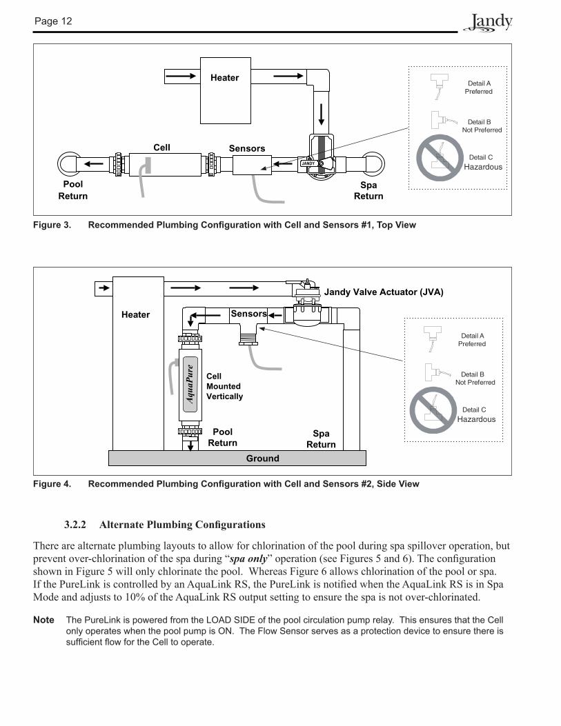
The preferred installation is that the Sensors and Cell are plumbed in the return line to the pool after (downstream)allthepoolequipment,suchasthefilterorheater.TheCellandSensorTeefittingaredesigned to be plumbed into 2” PVC pipe. Adapters can be used for systems with 1.5” plumbing. Figures 3 and4illustratetherecommendedplumbingconfiguration,whichresultinthemostreliableoperation.
Note The PureLink is powered from the LOAD SIDE of the pool circulation pump relay. This ensures that the Cell only operates when the pool pump is ON. The Flow Sensor serves as a protection device to ensure there is sufficient flow for the cell to operate.
WARNINGWhen using electrical products, basic precautions should always be followed, including the following:• RISK OF ELECTRIC SHOCK WHICH CAN RESULT IN SERIOUS INJURY OR DEATH. Before
attempting installation or service, ensure that all power to the device is disconnected/turned off at the circuit breaker.
• Grounding is required. The unit should be installed by a qualified service representative and should be properly grounded. (See Section 3.4, Earth Bonding).
• Install to permit access for servicing.• Read Section 1, Safety Information. Before attempting any electrical wiring, be sure to read
and follow Safety Instructions. Wiring should only be attempted by a qualified professional.
Page 12
Figure 4. Recommended Plumbing Configuration with Cell and Sensors #2, Side View
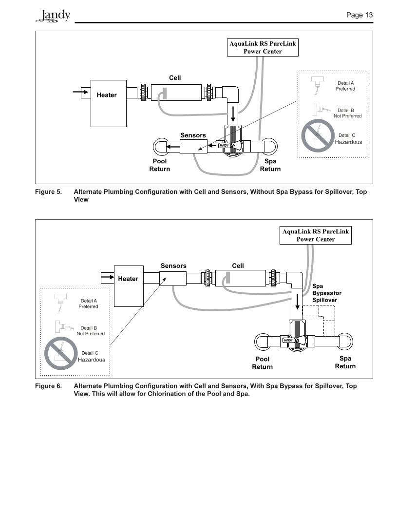
3.2.2 AlternatePlumbingConfigurations
There are alternate plumbing layouts to allow for chlorination of the pool during spa spillover operation, but prevent over-chlorination of the spa during “spa only”operation(seeFigures5and6).Theconfigurationshown in Figure 5 will only chlorinate the pool. Whereas Figure 6 allows chlorination of the pool or spa. IfthePureLinkiscontrolledbyanAquaLinkRS,thePureLinkisnotifiedwhentheAquaLinkRSisinSpaMode and adjusts to 10% of the AquaLink RS output setting to ensure the spa is not over-chlorinated.
Note The PureLink is powered from the LOAD SIDE of the pool circulation pump relay. This ensures that the Cell only operates when the pool pump is ON. The Flow Sensor serves as a protection device to ensure there is sufficient flow for the Cell to operate.
SpaReturn
Sensors
PoolReturn
Aqu
aPur
e
Heater
Ground
CellMountedVertically
Jandy Valve Actuator (JVA)
Detail A
Detail B
Detail C
Preferred
Not Preferred
Hazardous
Figure 3. Recommended Plumbing Configuration with Cell and Sensors #1, Top View
PoolReturn
SpaReturn
Cell Sensors
Heater
JANDY
Detail A
Detail B
Detail C
Preferred
Not Preferred
Hazardous
Page 13
PoolReturn
SpaReturn
Cell
Sensors
Heater
AquaLink RS PureLinkPower Center
JANDYJANDY
Figure 5. Alternate Plumbing Configuration with Cell and Sensors, Without Spa Bypass for Spillover, Top View
Detail A
Detail B
Detail C
Preferred
Not Preferred
Hazardous
SpaBypassforSpillover
PoolReturn
CellSensors
Heater
SpaReturn
JANDYJANDY
AquaLink RS PureLinkPower Center
Figure 6. Alternate Plumbing Configuration with Cell and Sensors, With Spa Bypass for Spillover, Top View. This will allow for Chlorination of the Pool and Spa.
Detail A
Detail B
Detail C
Preferred
Not Preferred
Hazardous
Page 14
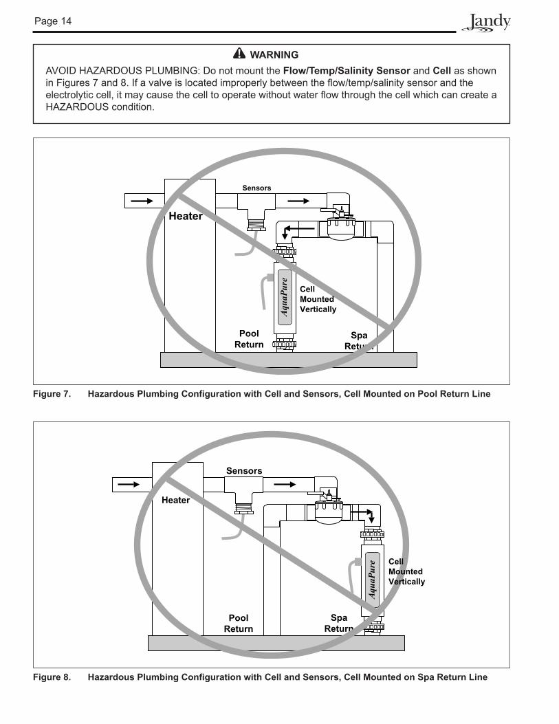
WARNINGAVOID HAZARDOUS PLUMBING: Do not mount the Flow/Temp/Salinity Sensor and Cell as shown in Figures 7 and 8. If a valve is located improperly between the flow/temp/salinity sensor and the electrolytic cell, it may cause the cell to operate without water flow through the cell which can create a HAZARDOUS condition.
SpaReturn
Sensors
Aqu
aPur
e
Heater
PoolReturn
CellMountedVertically
Figure 7. Hazardous Plumbing Configuration with Cell and Sensors, Cell Mounted on Pool Return Line
Aqu
aPur
e
SpaReturn
Sensors
PoolReturn
Heater
CellMountedVertically
Figure 8. Hazardous Plumbing Configuration with Cell and Sensors, Cell Mounted on Spa Return Line
Page 15
CAUTIONThe Power Center is not to be considered as suitable for use as Service Equipment. Therefore, it is required to have the appropriate means of disconnection, circuit isolation, and/or branch circuit protection installed upstream of the Power Center.
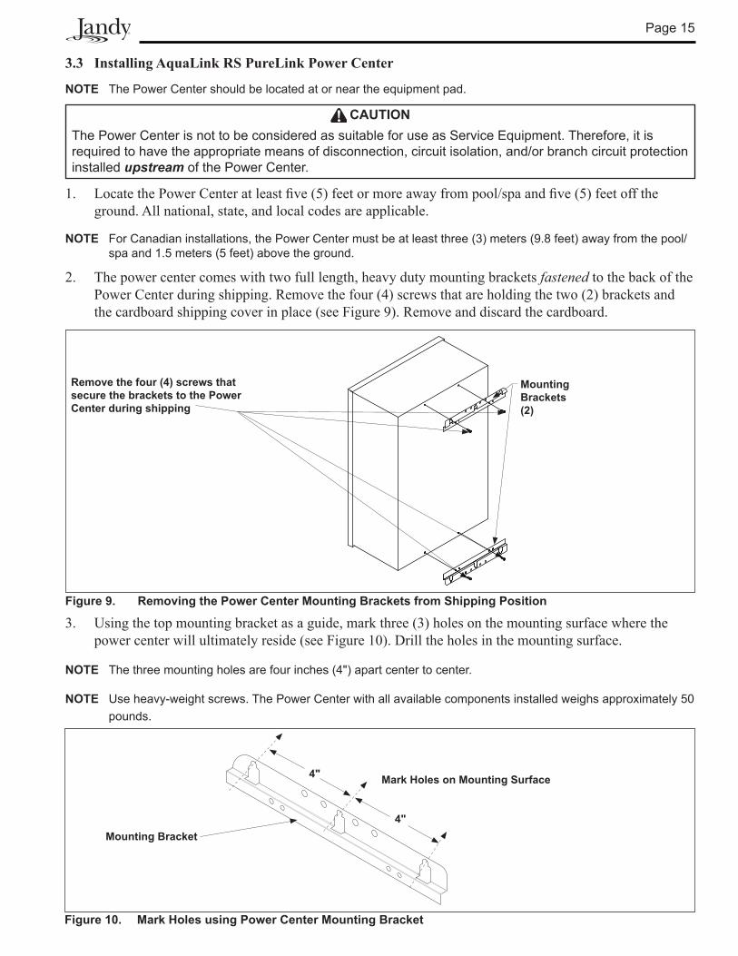
Figure 9. Removing the Power Center Mounting Brackets from Shipping Position
Remove the four (4) screws that secure the brackets to the Power Center during shipping
Mounting Brackets (2)
Figure 10. Mark Holes using Power Center Mounting Bracket
Mounting Bracket
Mark Holes on Mounting Surface4"
4"
3.3 Installing AquaLink RS PureLink Power Center
NOTE The Power Center should be located at or near the equipment pad.
1. LocatethePowerCenteratleastfive(5)feetormoreawayfrompool/spaandfive(5)feetofftheground. All national, state, and local codes are applicable.
NOTE For Canadian installations, the Power Center must be at least three (3) meters (9.8 feet) away from the pool/spa and 1.5 meters (5 feet) above the ground.
2. The power center comes with two full length, heavy duty mounting brackets fastened to the back of the Power Center during shipping. Remove the four (4) screws that are holding the two (2) brackets and the cardboard shipping cover in place (see Figure 9). Remove and discard the cardboard.
3. Using the top mounting bracket as a guide, mark three (3) holes on the mounting surface where the power center will ultimately reside (see Figure 10). Drill the holes in the mounting surface.
NOTE The three mounting holes are four inches (4") apart center to center.
NOTE Use heavy-weight screws. The Power Center with all available components installed weighs approximately 50 pounds.
Page 16
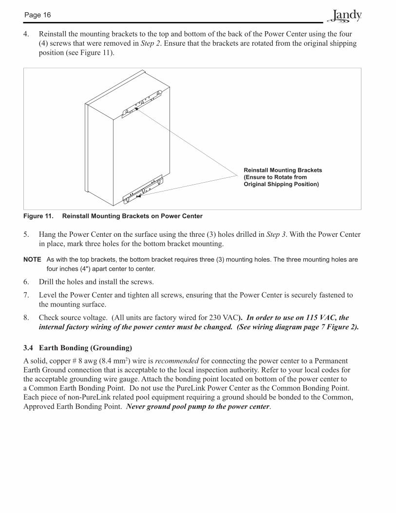
4. Reinstall the mounting brackets to the top and bottom of the back of the Power Center using the four (4) screws that were removed in Step 2. Ensure that the brackets are rotated from the original shipping position (see Figure 11).
Reinstall Mounting Brackets (Ensure to Rotate from Original Shipping Position)
Figure 11. Reinstall Mounting Brackets on Power Center
5. Hang the Power Center on the surface using the three (3) holes drilled in Step 3. With the Power Center in place, mark three holes for the bottom bracket mounting.
NOTE As with the top brackets, the bottom bracket requires three (3) mounting holes. The three mounting holes are four inches (4") apart center to center.
6. Drill the holes and install the screws.
7. Level the Power Center and tighten all screws, ensuring that the Power Center is securely fastened to the mounting surface.
8. Check source voltage. (All units are factory wired for 230 VAC). In order to use on 115 VAC, the internal factory wiring of the power center must be changed. (See wiring diagram page 7 Figure 2).
3.4 Earth Bonding (Grounding)
A solid, copper # 8 awg (8.4 mm2) wire is recommended for connecting the power center to a Permanent Earth Ground connection that is acceptable to the local inspection authority. Refer to your local codes for the acceptable grounding wire gauge. Attach the bonding point located on bottom of the power center to a Common Earth Bonding Point. Do not use the PureLink Power Center as the Common Bonding Point. Each piece of non-PureLink related pool equipment requiring a ground should be bonded to the Common, Approved Earth Bonding Point. Never ground pool pump to the power center.
Page 17
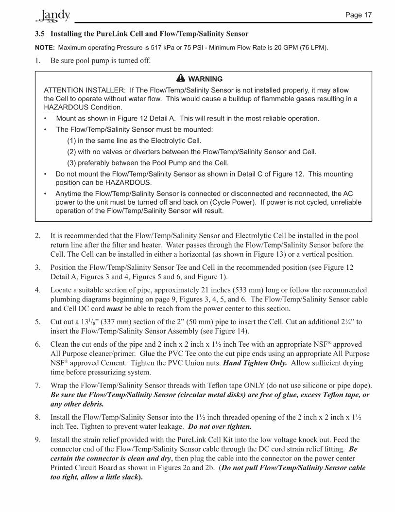
WARNINGATTENTION INSTALLER: If The Flow/Temp/Salinity Sensor is not installed properly, it may allow the Cell to operate without water flow. This would cause a buildup of flammable gases resulting in a HAZARDOUS Condition.• Mount as shown in Figure 12 Detail A. This will result in the most reliable operation.• The Flow/Temp/Salinity Sensor must be mounted: (1) in the same line as the Electrolytic Cell. (2) with no valves or diverters between the Flow/Temp/Salinity Sensor and Cell. (3) preferably between the Pool Pump and the Cell.• Do not mount the Flow/Temp/Salinity Sensor as shown in Detail C of Figure 12. This mounting
position can be HAZARDOUS.• Anytime the Flow/Temp/Salinity Sensor is connected or disconnected and reconnected, the AC
power to the unit must be turned off and back on (Cycle Power). If power is not cycled, unreliable operation of the Flow/Temp/Salinity Sensor will result.
3.5 Installing the PureLink Cell and Flow/Temp/Salinity Sensor
NOTE: Maximum operating Pressure is 517 kPa or 75 PSI - Minimum Flow Rate is 20 GPM (76 LPM).
1. Be sure pool pump is turned off.
2. It is recommended that the Flow/Temp/Salinity Sensor and Electrolytic Cell be installed in the pool returnlineafterthefilterandheater.WaterpassesthroughtheFlow/Temp/SalinitySensorbeforetheCell. The Cell can be installed in either a horizontal (as shown in Figure 13) or a vertical position.
3. Position the Flow/Temp/Salinity Sensor Tee and Cell in the recommended position (see Figure 12 Detail A, Figures 3 and 4, Figures 5 and 6, and Figure 1).
4. Locate a suitable section of pipe, approximately 21 inches (533 mm) long or follow the recommended plumbing diagrams beginning on page 9, Figures 3, 4, 5, and 6. The Flow/Temp/Salinity Sensor cable and Cell DC cord must be able to reach from the power center to this section.
5. Cut out a 131/8” (337 mm) section of the 2” (50 mm) pipe to insert the Cell. Cut an additional 2¼” to insert the Flow/Temp/Salinity Sensor Assembly (see Figure 14).
6. Clean the cut ends of the pipe and 2 inch x 2 inch x 1½ inch Tee with an appropriate NSF® approved All Purpose cleaner/primer. Glue the PVC Tee onto the cut pipe ends using an appropriate All Purpose NSF® approved Cement. Tighten the PVC Union nuts. Hand Tighten Only. Allowsufficientdryingtime before pressurizing system.
7. Wrap the Flow/Temp/Salinity SensorthreadswithTeflontapeONLY(donotusesiliconeorpipedope).Be sure the Flow/Temp/Salinity Sensor (circular metal disks) are free of glue, excess Teflon tape, or any other debris.
8. Install the Flow/Temp/Salinity Sensor into the 1½ inch threaded opening of the 2 inch x 2 inch x 1½ inch Tee. Tighten to prevent water leakage. Do not over tighten.
9. Install the strain relief provided with the PureLink Cell Kit into the low voltage knock out. Feed the connector end of the Flow/Temp/Salinity SensorcablethroughtheDCcordstrainrelieffitting.Be certain the connector is clean and dry, then plug the cable into the connector on the power center Printed Circuit Board as shown in Figures 2a and 2b. (Do not pull Flow/Temp/Salinity Sensor cable too tight, allow a little slack).
Page 18
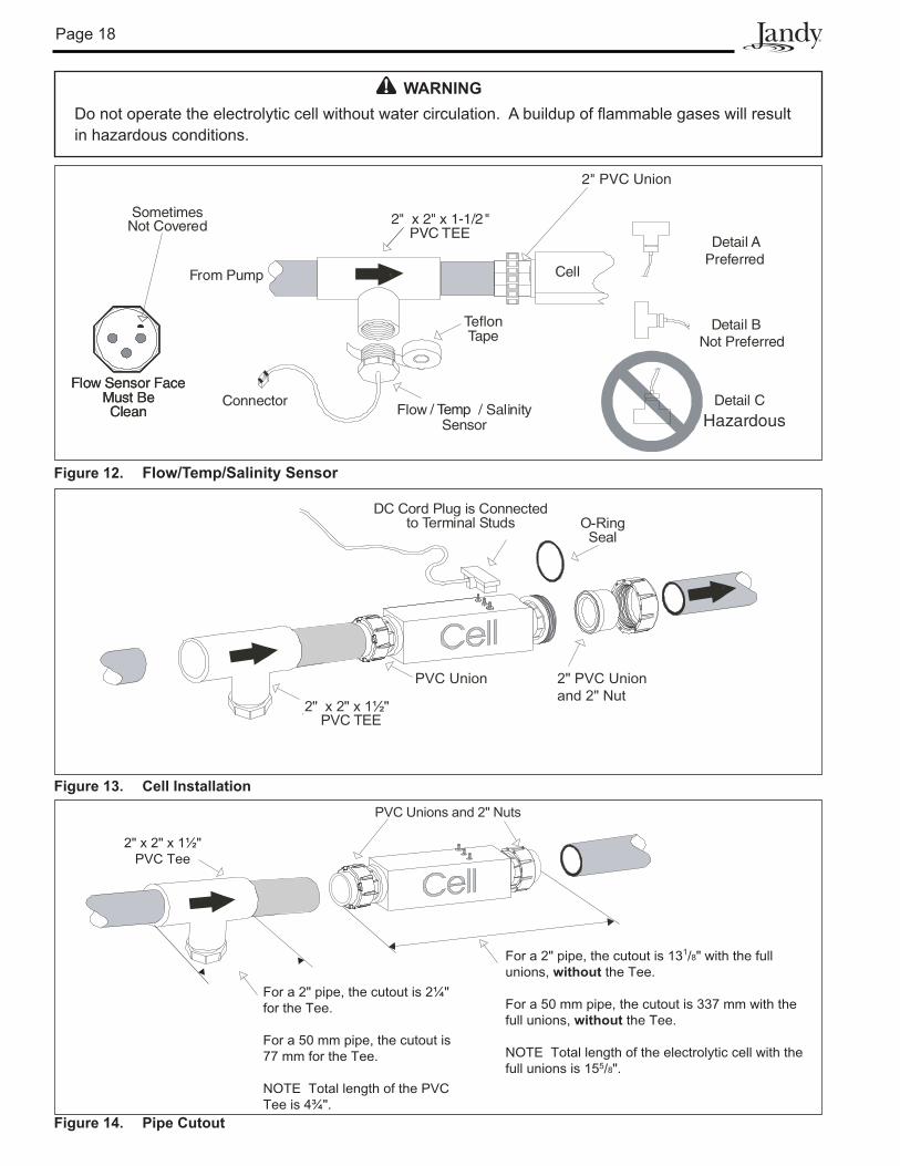
Figure 13. Cell Installation
O-RingSeal
DC Cord Plug is Connectedto Terminal Studs
PVC Union 2" PVC Unionand 2" Nut
2" x 2" x 1½"PVC TEE
Figure 14. Pipe Cutout
PVC Unions and 2" Nuts
For a 2" pipe, the cutout is 131/8" with the fullunions, without the Tee.
For a 50 mm pipe, the cutout is 337 mm with thefull unions, without the Tee.
NOTE Total length of the electrolytic cell with thefull unions is 155/8".
2" x 2" x 1½"PVC Tee
For a 2" pipe, the cutout is 2¼"for the Tee.
For a 50 mm pipe, the cutout is77 mm for the Tee.
NOTE Total length of the PVCTee is 4¾".
Figure 12. Flow/Temp/Salinity Sensor
Flow Sensor FaceMust BeClean
Connector
Sensor
2" x 2" x 1-1/2"PVC TEE
From Pump
TeflonTape
Cell
Detail A
Detail B
Detail C
Preferred
Not Preferred
Hazardous
SometimesNot Covered
Flow Sensor FaceMust BeClean i / Sal nityFlow / Temp
2" PVC Union
WARNINGDo not operate the electrolytic cell without water circulation. A buildup of flammable gases will result in hazardous conditions.
Page 19
CAUTIONDo not overtighten the strain relief fitting. Overtightening can cause damage to the Flow/Temp/Salinity Sensor cable or DC cord.
10. Plug the DC cord into the Cell stud terminals protruding from the Cell top (see Figure 13). The DC cord can be plugged into the cell in either direction.
11. ConnecttheDCcordtothePowercenter.FeedtheDCcordthroughthesamestrainrelieffittingasthe Flow/Temp/Salinity Sensor. Plug the DC cord into the two spade connectors of the wiring harness located in the low voltage raceway of the power center, see Figure 2. This wiring harness establishes the connection between the Cell and the Printed Circuit Board mounted on the back plate.
12.TightenstrainrelieffittingscrewsfortheFlow/Temp/Salinity Sensor and the DC cord. Do not pull Flow/Temp/Salinity Sensor cable or DC Cord too tight. Allow a little slack cable inside of Power center Enclosure.
13. Prior to reattaching front cover, check the wiring. Be sure the Flow/Temp/Salinity Sensor is plugged in. The DC cord should be plugged in. Also, check the AC wiring.
14. Plug the ribbon cable attached to the front cover PC board into Printed Circuit Board mounted on the backplate (see Figure 2). Now reattach the power center front cover to the backplate.
3.6 Connection to the AquaLink® RS PureLink Control System
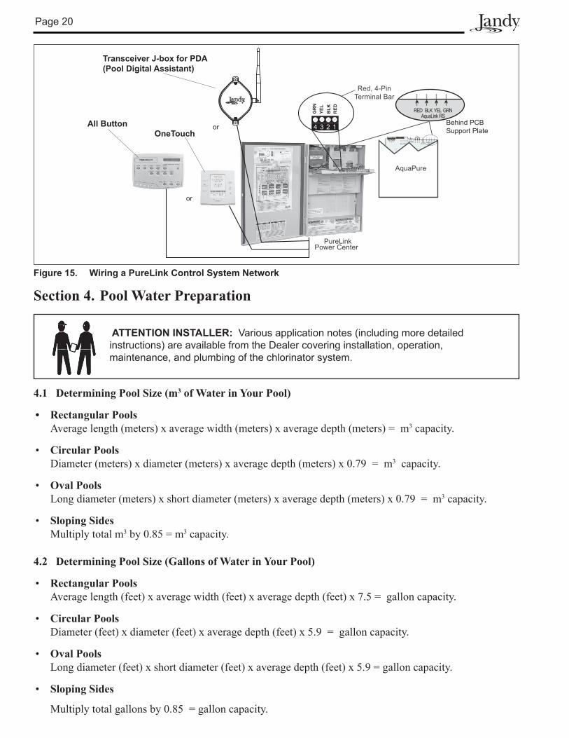
The Jandy AquaLink RS PureLink is a multi-function pool controller and can fully control the function of the AquaPure chlorine generator. The AquaPure will display JA when a button is pressed at the AquaPure while the Jandy AquaLink RS PureLink is in control. Adjustment of the AquaPure chlorine production rate can be controlled from the main menu of the AquaLink RS Controller (All Button, OneTouch, or PDA). Boost mode may be activated from the AquaPure while the AquaLink RS is online. Refer to the AquaLink RS Operation Manual (or AquaLink RS PDA Operation Manual) for more information. The AquaPure temperature, salinity, service codes, and LED indicators operate as normal.
NOTE The AquaPure Chlorine Generator will communicate with AquaLink RS using firmware versions JJ or later.
ReferringtoFigures2aor2b,wirethePureLinkPowerCentertransformertotheloadsideofthefilterpump relay.
NOTE The screw terminals are removable to aid in installation.
Page 20
ATTENTION INSTALLER: Various application notes (including more detailed instructions) are available from the Dealer covering installation, operation, maintenance, and plumbing of the chlorinator system.
Section 4. Pool Water Preparation
4.1 Determining Pool Size (m3 of Water in Your Pool)
• Rectangular Pools Average length (meters) x average width (meters) x average depth (meters) = m3 capacity.
• Circular Pools Diameter (meters) x diameter (meters) x average depth (meters) x 0.79 = m3 capacity.
• Oval Pools Long diameter (meters) x short diameter (meters) x average depth (meters) x 0.79 = m3 capacity.
• Sloping Sides Multiply total m3 by 0.85 = m3 capacity.
4.2 Determining Pool Size (Gallons of Water in Your Pool)
• Rectangular Pools Average length (feet) x average width (feet) x average depth (feet) x 7.5 = gallon capacity.
• Circular Pools Diameter (feet) x diameter (feet) x average depth (feet) x 5.9 = gallon capacity.
• Oval Pools Long diameter (feet) x short diameter (feet) x average depth (feet) x 5.9 = gallon capacity.
• Sloping Sides
Multiply total gallons by 0.85 = gallon capacity.
Figure 15. Wiring a PureLink Control System Network
PureLinkPower Center
Front PCBReverse Side
Test PointsA to K
FlowSensor R S
TestSwitches
Aux BoardH ORP
24 VACRed BLK YEL GRN
AquaLink RS
or
4 3 2 1
RED
BLK
YEL
GR
N
RED BLK YEL GRNAquaLink RS
AquaPure
Red, 4-PinTerminal Bar
or Behind PCB Support Plate
All ButtonOneTouch
Transceiver J-box for PDA (Pool Digital Assistant)
Page 21
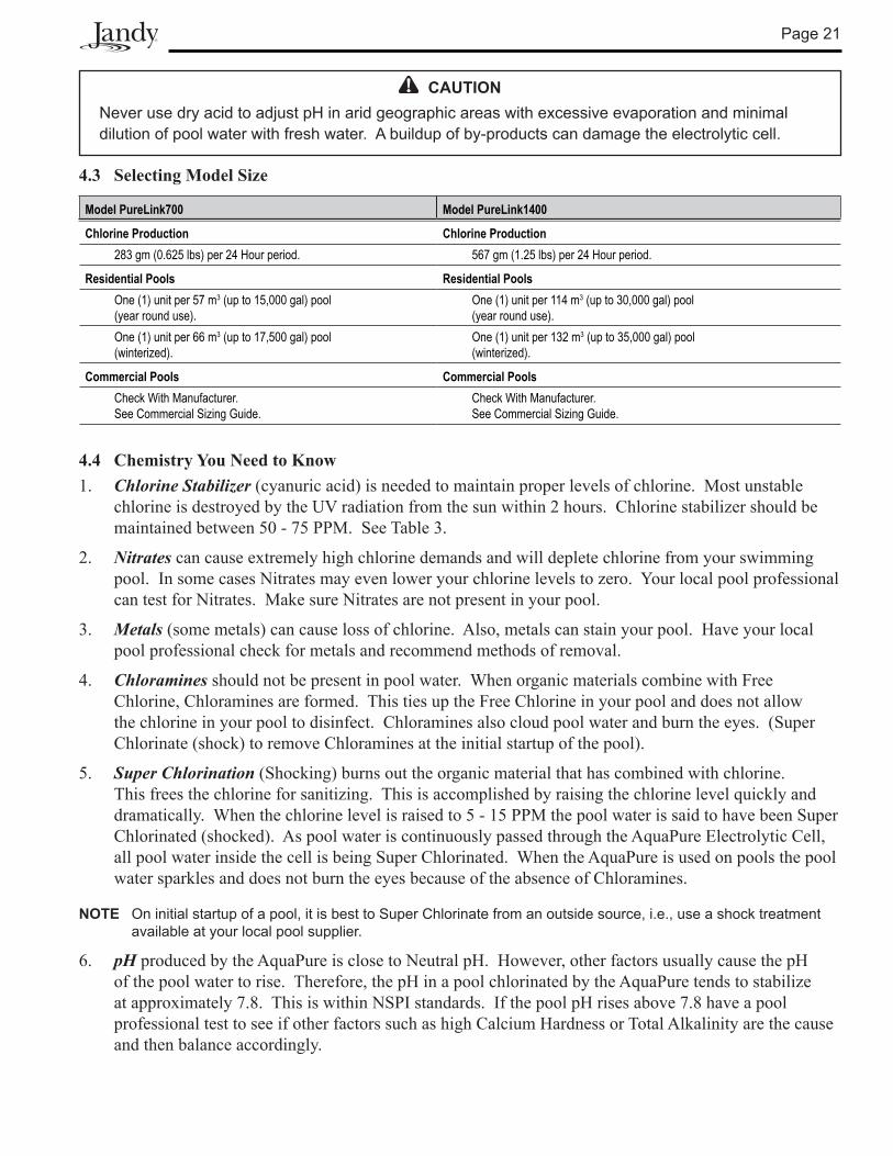
4.3 Selecting Model Size
Model PureLink700 Model PureLink1400
Chlorine Production Chlorine Production283 gm (0.625 lbs) per 24 Hour period. 567 gm (1.25 lbs) per 24 Hour period.
Residential Pools Residential PoolsOne (1) unit per 57 m3 (up to 15,000 gal) pool (year round use).
One (1) unit per 114 m3 (up to 30,000 gal) pool (year round use).
One (1) unit per 66 m3 (up to 17,500 gal) pool (winterized).
One (1) unit per 132 m3 (up to 35,000 gal) pool (winterized).
Commercial Pools Commercial PoolsCheck With Manufacturer. See Commercial Sizing Guide.
Check With Manufacturer. See Commercial Sizing Guide.
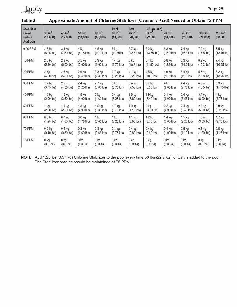
4.4 Chemistry You Need to Know1. Chlorine Stabilizer (cyanuric acid) is needed to maintain proper levels of chlorine. Most unstable
chlorine is destroyed by the UV radiation from the sun within 2 hours. Chlorine stabilizer should be maintained between 50 - 75 PPM. See Table 3.
2. Nitrates can cause extremely high chlorine demands and will deplete chlorine from your swimming pool. In some cases Nitrates may even lower your chlorine levels to zero. Your local pool professional can test for Nitrates. Make sure Nitrates are not present in your pool.
3. Metals (some metals) can cause loss of chlorine. Also, metals can stain your pool. Have your local pool professional check for metals and recommend methods of removal.
4. Chloramines should not be present in pool water. When organic materials combine with Free Chlorine, Chloramines are formed. This ties up the Free Chlorine in your pool and does not allow the chlorine in your pool to disinfect. Chloramines also cloud pool water and burn the eyes. (Super Chlorinate (shock) to remove Chloramines at the initial startup of the pool).
5. Super Chlorination (Shocking) burns out the organic material that has combined with chlorine. This frees the chlorine for sanitizing. This is accomplished by raising the chlorine level quickly and dramatically. When the chlorine level is raised to 5 - 15 PPM the pool water is said to have been Super Chlorinated (shocked). As pool water is continuously passed through the AquaPure Electrolytic Cell, all pool water inside the cell is being Super Chlorinated. When the AquaPure is used on pools the pool water sparkles and does not burn the eyes because of the absence of Chloramines.
NOTE On initial startup of a pool, it is best to Super Chlorinate from an outside source, i.e., use a shock treatment available at your local pool supplier.
6. pH produced by the AquaPure is close to Neutral pH. However, other factors usually cause the pH of the pool water to rise. Therefore, the pH in a pool chlorinated by the AquaPure tends to stabilize at approximately 7.8. This is within NSPI standards. If the pool pH rises above 7.8 have a pool professional test to see if other factors such as high Calcium Hardness or Total Alkalinity are the cause and then balance accordingly.
CAUTIONNever use dry acid to adjust pH in arid geographic areas with excessive evaporation and minimal dilution of pool water with fresh water. A buildup of by-products can damage the electrolytic cell.
Page 22
7. Total Dissolved Solids (TDS) Adding salt to pool water will raise the TDS level. While this does not adversely affect the pool water chemistry or clarity, the pool water professional testing for TDS must be made aware salt has been added for the AquaPure system. The individual performing the TDS test will then subtract the salinity level to arrive at the correct TDS level.
8. NewPoolWaterinarecentlyfilledornewlyrefinishedpoolmaycontainundesirablematter.Thisundesirable matter could interfere with the AquaPure’s ability to chlorinate properly. Make sure the water is tested by a pool professional and properly balanced before turning on the AquaPure.
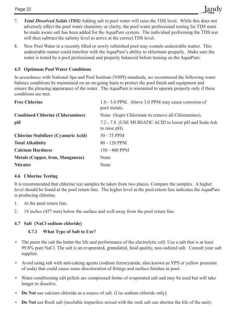
4.5 Optimum Pool Water Conditions
In accordance with National Spa and Pool Institute (NSPI) standards, we recommend the following water balanceconditionsbemaintainedonanon-goingbasistoprotectthepoolfinishandequipmentandensure the pleasing appearance of the water. The AquaPure is warranted to operate properly only if these conditions are met.
Free Chlorine 1.0 - 3.0 PPM. Above 3.0 PPM may cause corrosion of pool metals.
Combined Chlorine (Chloramines) None (Super Chlorinate to remove all Chloramines).pH 7.2 - 7.8 (USE MURIATIC ACID to lower pH and Soda Ash
to raise pH). Chlorine Stabilizer (Cyanuric Acid) 50 - 75 PPMTotal Alkalinity 80 - 120 PPMCalcium Hardness 150 - 400 PPMMetals (Copper, Iron, Manganese) NoneNitrates None
4.6 Chlorine Testing
It is recommended that chlorine test samples be taken from two places. Compare the samples. A higher level should be found at the pool return line. The higher level at the pool return line indicates the AquaPure is producing chlorine.
1. At the pool return line.
2. 18 inches (457 mm) below the surface and well away from the pool return line.
4.7 Salt (NaCl sodium chloride)
4.7.1 What Type of Salt to Use?
• The purer the salt the better the life and performance of the electrolytic cell. Use a salt that is at least 99.8% pure NaCl. The salt is an evaporated, granulated, food quality, non-iodized salt. Consult your salt supplier.
• Avoid using salt with anti-caking agents (sodium ferrocyanide, also known as YPS or yellow prussiate ofsoda)thatcouldcausesomediscolorationoffittingsandsurfacefinishesinpool.
• Water conditioning salt pellets are compressed forms of evaporated salt and may be used but will take longer to dissolve.
• Do Not use calcium chloride as a source of salt. (Use sodium chloride only).
• Do Not use Rock salt (insoluble impurities mixed with the rock salt can shorten the life of the unit).
Page 23
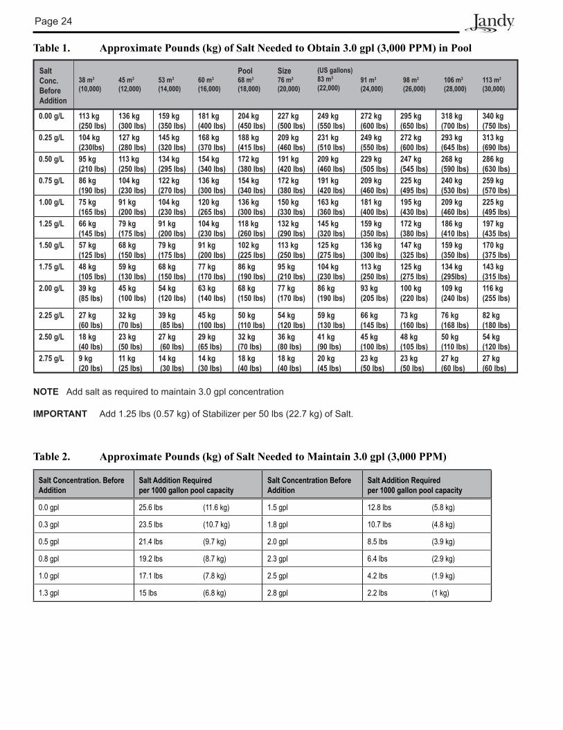
4.7.2 How Much Salt to Use?
Use Table 1 to determine how much salt will be needed. Most pools contain some salt depending on the water source and chemicals used for sanitizing. If the AquaPure has not been wired and turned on yet, a hand held meter calibrated for NaCl (salt) can be used to determine the existing salt concentration of the water. If the AquaPure is wired in (connected), use it to determine the salinity.
Set Chlorine Production to 00%. Operating the unit above 00% production without salt will damage Cell. The Salinity button C on the AquaPure can be used to determine salinity in the case of a new pool installation, or a complete water change so long as the Chlorine Production is set to 00%. See Section 5.4.2, step 2.
• 3.0 to 3.5 gpl of salt is recommended for optimum water conditions.
• Low salt concentration below 2.0 gpl will cause premature cell failure.
• High salt concentration above 4.0 gpl may damage the power center.
• Highsaltconcentrationabove6.0gplmaycausecorrosiondamagetopoolfixtures.
NOTE Should too much salt be inadvertently added to the pool see Section 7, Troubleshooting.
NOTE To convert gpl (grams per liter) of a salt solution to PPM (Parts Per Million) of a salt solution multiply by 1000, i.e., 3.0 gpl salt X 1000 = 3000 PPM salt.
4.7.3 How to Add Salt to the Pool?
1. Turn on pump to circulate pool water.
2. IMPORTANT - Turn the AquaPure off by pressing the arrow button A and setting CHLORINE PRODUCTION Rate to 00%.
3. Determine amount of salt from the following charts.
4. Broadcast or spread the salt into the outer perimeter of the pool, or into the shallow end of the pool for quick and even distribution.
5. To avoid clogging the filter or damaging power center and pump, do not add salt through the skimmer, main drain, or surge tank.
6. Brush the pool bottom and allow water to circulate for 24 hours to dissolve completely and mix evenly with the pool water.
7. After 24 hours, verify correct salt reading.
8. Turn on the AquaPure and set to desired Production rate (Press arrow button B ).
Page 24
Table 1. Approximate Pounds (kg) of Salt Needed to Obtain 3.0 gpl (3,000 PPM) in Pool
Salt Conc.BeforeAddition
38 m3
(10,000)45 m3
(12,000)53 m3
(14,000)60 m3
(16,000)
Pool68 m3
(18,000)
Size76 m3
(20,000)
(US gallons)83 m3
(22,000)91 m3
(24,000)98 m3
(26,000)106 m3
(28,000)113 m3
(30,000)
0.00 g/L 113 kg (250 lbs)
136 kg (300 lbs)
159 kg(350 lbs)
181 kg(400 lbs)
204 kg(450 lbs)
227 kg(500 lbs)
249 kg(550 lbs)
272 kg(600 lbs)
295 kg(650 lbs)
318 kg(700 lbs)
340 kg(750 lbs)
0.25 g/L 104 kg (230lbs)
127 kg (280 lbs)
145 kg(320 lbs)
168 kg(370 lbs)
188 kg(415 lbs)
209 kg(460 lbs)
231 kg(510 lbs)
249 kg(550 lbs)
272 kg(600 lbs)
293 kg(645 lbs)
313 kg(690 lbs)
0.50 g/L 95 kg (210 lbs)
113 kg (250 lbs)
134 kg(295 lbs)
154 kg(340 lbs)
172 kg(380 lbs)
191 kg(420 lbs)
209 kg(460 lbs)
229 kg(505 lbs)
247 kg(545 lbs)
268 kg(590 lbs)
286 kg(630 lbs)
0.75 g/L 86 kg (190 lbs)
104 kg (230 lbs)
122 kg(270 lbs)
136 kg(300 lbs)
154 kg(340 lbs)
172 kg(380 lbs)
191 kg(420 lbs)
209 kg(460 lbs)
225 kg(495 lbs)
240 kg(530 lbs)
259 kg(570 lbs)
1.00 g/L 75 kg (165 lbs)
91 kg (200 lbs)
104 kg(230 lbs)
120 kg(265 lbs)
136 kg(300 lbs)
150 kg(330 lbs)
163 kg(360 lbs)
181 kg(400 lbs)
195 kg(430 lbs)
209 kg(460 lbs)
225 kg(495 lbs)
1.25 g/L 66 kg (145 lbs)
79 kg (175 lbs)
91 kg(200 lbs)
104 kg(230 lbs)
118 kg(260 lbs)
132 kg(290 lbs)
145 kg(320 lbs)
159 kg(350 lbs)
172 kg(380 lbs)
186 kg(410 lbs)
197 kg(435 lbs)
1.50 g/L 57 kg (125 lbs)
68 kg (150 lbs)
79 kg(175 lbs)
91 kg(200 lbs)
102 kg(225 lbs)
113 kg(250 lbs)
125 kg(275 lbs)
136 kg(300 lbs)
147 kg(325 lbs)
159 kg(350 lbs)
170 kg(375 lbs)
1.75 g/L 48 kg (105 lbs)
59 kg (130 lbs)
68 kg(150 lbs)
77 kg(170 lbs)
86 kg(190 lbs)
95 kg(210 lbs)
104 kg(230 lbs)
113 kg(250 lbs)
125 kg(275 lbs)
134 kg(295lbs)
143 kg(315 lbs)
2.00 g/L 39 kg (85 lbs)
45 kg (100 lbs)
54 kg(120 lbs)
63 kg(140 lbs)
68 kg(150 lbs)
77 kg(170 lbs)
86 kg(190 lbs)
93 kg(205 lbs)
100 kg(220 lbs)
109 kg(240 lbs)
116 kg(255 lbs)
2.25 g/L 27 kg (60 lbs)
32 kg(70 lbs)
39 kg (85 lbs)
45 kg(100 lbs)
50 kg(110 lbs)
54 kg(120 lbs)
59 kg(130 lbs)
66 kg(145 lbs)
73 kg(160 lbs)
76 kg(168 lbs)
82 kg(180 lbs)
2.50 g/L 18 kg (40 lbs)
23 kg(50 lbs)
27 kg (60 lbs)
29 kg(65 lbs)
32 kg(70 lbs)
36 kg(80 lbs)
41 kg(90 lbs)
45 kg(100 lbs)
48 kg(105 lbs)
50 kg(110 lbs)
54 kg(120 lbs)
2.75 g/L 9 kg (20 lbs)
11 kg(25 lbs)
14 kg (30 lbs)
14 kg(30 lbs)
18 kg(40 lbs)
18 kg(40 lbs)
20 kg(45 lbs)
23 kg(50 lbs)
23 kg(50 lbs)
27 kg(60 lbs)
27 kg(60 lbs)
NOTE Add salt as required to maintain 3.0 gpl concentration
IMPORTANT Add 1.25 lbs (0.57 kg) of Stabilizer per 50 lbs (22.7 kg) of Salt.
Table 2. Approximate Pounds (kg) of Salt Needed to Maintain 3.0 gpl (3,000 PPM)
Salt Concentration. Before Addition
Salt Addition Required per 1000 gallon pool capacity
Salt Concentration Before Addition
Salt Addition Required per 1000 gallon pool capacity
0.0 gpl 25.6 lbs (11.6 kg) 1.5 gpl 12.8 lbs (5.8 kg)
0.3 gpl 23.5 lbs (10.7 kg) 1.8 gpl 10.7 lbs (4.8 kg)
0.5 gpl 21.4 lbs (9.7 kg) 2.0 gpl 8.5 lbs (3.9 kg)
0.8 gpl 19.2 lbs (8.7 kg) 2.3 gpl 6.4 lbs (2.9 kg)
1.0 gpl 17.1 lbs (7.8 kg) 2.5 gpl 4.2 lbs (1.9 kg)
1.3 gpl 15 lbs (6.8 kg) 2.8 gpl 2.2 lbs (1 kg)
Page 25
Table 3. Approximate Amount of Chlorine Stabilizer (Cyanuric Acid) Needed to Obtain 75 PPM
1Stabilizer Level Before Addition
38 m3
(10,000)45 m3
(12,000)53 m3
(14,000)60 m3
(16,000)
Pool68 m3
(18,000)
Size76 m3
(20,000)
(US gallons)83 m3
(22,000)91 m3
(24,000)98 m3
(26,000)106 m3
(28,000)13 m3
(30,000)
0.00 PPM 2.8 kg(6.25 lbs)
3.4 kg (7.50 lbs)
4 kg (8.75 lbs)
4.5 kg (10.0 lbs)
5 kg (11.25lb)
5.7 kg (12.5 lbs)
6.2 kg (13.75 lbs)
6.8 kg (15.0 lbs)
7.4 kg (16.3 lbs)
7.9 kg (17.5 lbs)
8.5 kg (18.75 lbs)
10 PPM 2.5 kg (5.40 lbs)
2.9 kg (6.50 lbs)
3.5 kg (7.60 lbs)
3.9 kg (8.60 lbs)
4.4 kg (9.75 lbs)
5 kg (10.8 lbs)
5.4 kg (11.90 lbs)
5.8 kg (12.9 lbs)
6.3 kg (14.0 lbs)
6.9 kg (15.2 lbs)
7.4 kg (16.25 lbs)
20 PPM 2 kg (4.60 lbs)
2.5 kg (5.50 lbs)
2.9 kg (6.40 lbs)
3.3 kg (7.30 lbs)
3.7 kg (8.25 lbs)
4.1 kg (9.20 lbs)
4.5 kg (10.0 lbs)
4.9 kg (10.9 lbs)
5.4 kg (11.9 lbs)
5.8 kg (12.8 lbs)
6.2 kg (13.75 lbs)
30 PPM 1.7 kg (3.75 lbs)
2 kg (4.50 lbs)
2.4 kg (5.25 lbs)
2.7 kg (6.00 lbs)
3 kg (6.75 lbs)
3.4 kg (7.50 lbs)
3.7 kg (8.25 lbs)
4 kg (9.00 lbs)
4.4 kg (9.75 lbs)
4.8 kg (10.5 lbs)
5.3 kg (11.75 lbs)
40 PPM 1.3 kg (2.90 lbs)
1.6 kg (3.50 lbs)
1.8 kg (4.00 lbs)
2 kg (4.60 lbs)
2.4 kg (5.25 lbs)
2.6 kg (5.80 lbs)
2.9 kg (6.40 lbs)
3.1 kg (6.90 lbs)
3.4 kg (7.58 lbs)
3.7 kg (8.20 lbs)
4 kg (8.75 lbs)
50 PPM 1 kg (2.00 lbs)
1.1 kg (2.50 lbs)
1.3 kg (2.90 lbs)
1.5 kg (3.30 lbs)
1.7 kg (3.75 lbs)
1.9 kg (4.10 lbs)
2 kg (4.60 lbs)
2.2 kg (4.90 lbs)
2.4 kg (5.40 lbs)
2.6 kg (5.80 lbs)
2.8 kg (6.25 lbs)
60 PPM 0.5 kg (1.25 lbs)
0.7 kg (1.50 lbs)
0.8 kg (1.75 lbs)
1 kg (2.00 lbs)
1 kg (2.25 lbs)
1.1 kg (2.50 lbs)
1.2 kg (2.75 lbs)
1.4 kg (3.00 lbs)
1.5 kg (3.25 lbs)
1.6 kg (3.50 lbs)
1.7 kg (3.75 lbs)
70 PPM 0.2 kg (0.40 lbs)
0.2 kg (0.50 lbs)
0.3 kg (0.60 lbs)
0.3 kg (0.66 lbs)
0.3 kg (0.75 lbs)
0.4 kg (0.80 lbs)
0.4 kg (0.90 lbs)
0.4 kg (1.00 lbs)
0.5 kg (1.10 lbs)
0.5 kg (1.20 lbs)
0.6 kg (1.25 lbs)
75 PPM 0 kg(0.0 lbs)
0 kg(0.0 lbs)
0 kg(0.0 lbs)
0 kg(0.0 lbs)
0 kg(0.0 lbs)
0 kg(0.0 lbs)
0 kg(0.0 lbs)
0 kg(0.0 lbs)
0 kg(0.0 lbs)
0 kg(0.0 lbs)
0 kg(0.0 lbs)
NOTE Add 1.25 lbs (0.57 kg) Chlorine Stabilizer to the pool every time 50 lbs (22.7 kg) of Salt is added to the pool. The Stabilizer reading should be maintained at 75 PPM.
Page 26
Section 5. Operating Instructions
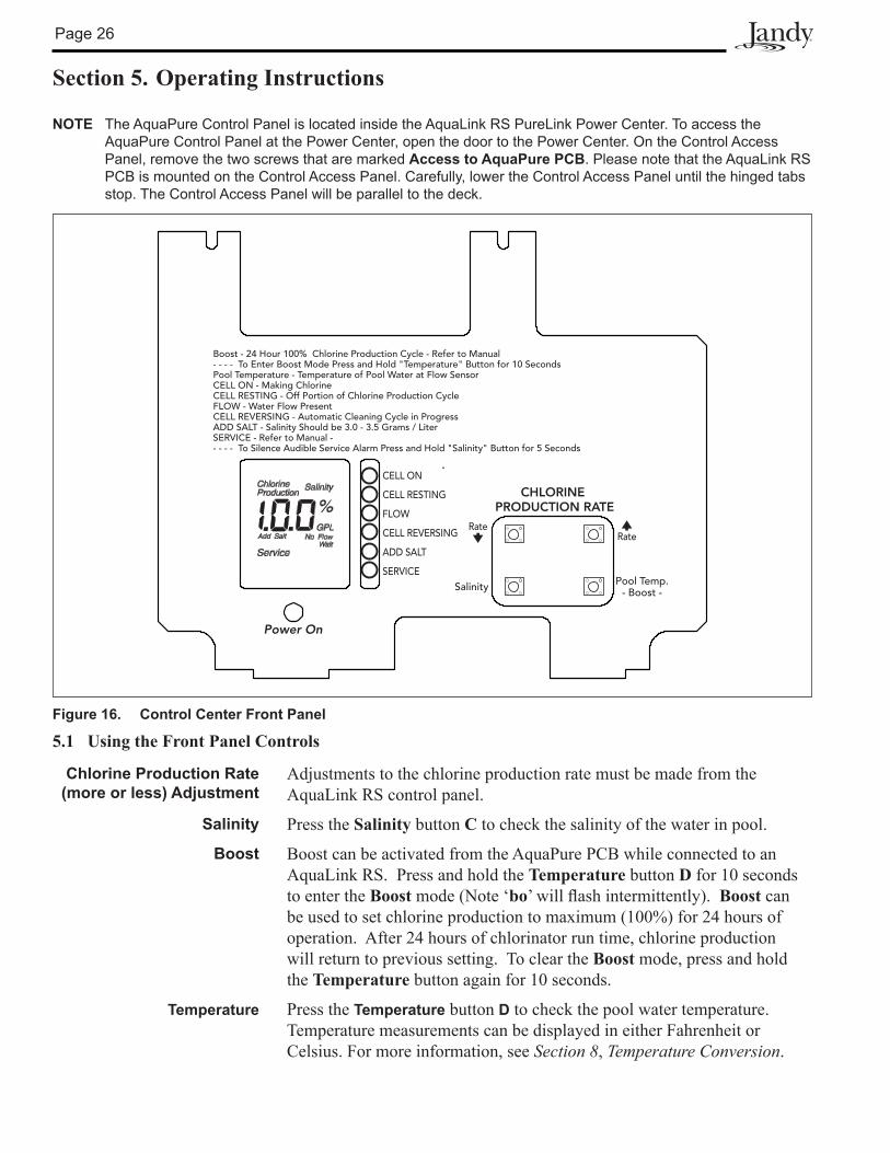
NOTE The AquaPure Control Panel is located inside the AquaLink RS PureLink Power Center. To access the AquaPure Control Panel at the Power Center, open the door to the Power Center. On the Control Access Panel, remove the two screws that are marked Access to AquaPure PCB. Please note that the AquaLink RS PCB is mounted on the Control Access Panel. Carefully, lower the Control Access Panel until the hinged tabs stop. The Control Access Panel will be parallel to the deck.
5.1 Using the Front Panel Controls
Chlorine Production Rate (more or less) Adjustment
Adjustments to the chlorine production rate must be made from the AquaLink RS control panel.
Salinity Press the Salinity button C to check the salinity of the water in pool.
Boost Boost can be activated from the AquaPure PCB while connected to an AquaLink RS. Press and hold the Temperature button D for 10 seconds to enter the Boost mode (Note ‘bo’willflashintermittently).Boost can be used to set chlorine production to maximum (100%) for 24 hours of operation. After 24 hours of chlorinator run time, chlorine production will return to previous setting. To clear the Boost mode, press and hold the Temperature button again for 10 seconds.
Temperature Press the Temperature button D to check the pool water temperature. Temperature measurements can be displayed in either Fahrenheit or Celsius. For more information, see Section 8, Temperature Conversion.
Figure 16. Control Center Front Panel
Boost - 24 Hour 100% Chlorine Production Cycle - Refer to Manual- - - - To Enter Boost Mode Press and Hold "Temperature" Button for 10 SecondsPool Temperature - Temperature of Pool Water at Flow SensorCELL ON - Making ChlorineCELL RESTING - Off Portion of Chlorine Production CycleFLOW - Water Flow PresentCELL REVERSING - Automatic Cleaning Cycle in ProgressADD SALT - Salinity Should be 3.0 - 3.5 Grams / LiterSERVICE - Refer to Manual -- - - - To Silence Audible Service Alarm Press and Hold "Salinity" Button for 5 Seconds
Power On
CELL ON
CELL RESTING
FLOW
CELL REVERSING
ADD SALT
SERVICE
CHLORINEPRODUCTION RATE
Salinity Pool Temp.- Boost -
RateRate
Page 27
5.2 Reading the Display
Cell On The CELL ON indicator shows that the cell has been turned on by the AquaPure. Some reasons for the CELL ON indicator not being on during normal operation, are: CHLORINE PRODUCTION set to 00%, CHLORINE PRODUCTION set to less than 100% and Cell Resting appears during cell rest period, NO FLOW condition, two minutes before automatic cleaning cycle, Low temperature cut off has been activated, or a service related problem such as a salinity level below 2.0 gpl or salinity level too high.
Cell Resting During the Normal chlorine production cycle when the unit is set for less than 100%, the cell will periodically rest; that is, the unit will not make chlorine. The CELL RESTING indicator shows that the cell has been turned off by the power center.
Flow or No Flow Indication WhenthepowercenterdeterminesthatwaterisflowingpasttheFlow/Temp/Salinity Sensor, the FLOWindicatorisdisplayed.Whennoflowisdetected, the NO FLOW is displayed and the cell is turned off.
Cell Reversing The automatic cleaning cycle of the AquaPure is in progress. The cleaning cycle is factory set and cannot be adjusted. Cell Reversing does not interrupt the production of Chlorine.
Salinity Salinity is displayed along with the gpl (grams per liter) indicator, when the Salinity button is depressed. If a reading of HH appears, the salinity is above 4.5 to 6.5 gpl (depending on pool temperature) and is too high to measure correctly (at normal temperatures). Maintain Salinity between 3.0 and 3.5 gpl. See Section 4.
Add Salt The ADD SALT indicator comes on when the Flow/Temp/Salinity Sensor determines that the salinity level of the pool water is too low. Maintain Salinity between 3.0 and 3.5 gpl.
Service and Service Code The SERVICE indicator will turn on whenever the AquaPure detects a problem that requires attention. The SERVICE indicator is accompanied by a service code displayed on the front panel, displayed as a 3 digit code. The service code(s) are displayed twice per minute with an audible alarm.
NOTE See Section 7.2, Service Codes. Problems can range from insufficient salinity to the DC cord not connected.
Audible Alarm Anaudiblealarm(beep)soundsonceperhour,andonlyforthefirstservice code when a Service condition is detected. The Alarm can be cleared by pressing and holding the Salinity button C for 5 seconds. The audible alarm can be cleared for 24 hours or until the power to the unit isturnedoffandbackonwhichevercomesfirst.However,theaudiblealarm will return if a new problem is detected.
NOTE The audible alarm can be permanently disabled by removing the blue jumper from J10 on the power center front cover PCB.
Page 28
Beeper Control Beeper operation and volume control can be adjusted.
To adjust volume control, press and hold the TEMPERATURE button for 15 seconds. The system will beep once when pressed, once after 10 seconds and once after 15 seconds. Release the key after the third beep.
Press the SALINITY button within 5 seconds to enter the temperature change screen.
The system will display a ‘1’ followed by ‘F’ or ‘C’. Press the TEMPERATURE button to move to the second parameter screen. The screen will display a 0, and the beeper volume will be fully reduced. The system will occasionally show a ‘2’ to display the screen number.
Press the arrow button B to increase the volume and the arrow button A to reduce the volume. The volume increments from 0 to 100 in 20 steps. After each press of the arrow buttons, the beeper will activate to demonstrate the current volume level.
When the beeper volume has been adjusted to the desired setting, press theSALINITYbuttontoconfirmthenewbeepervolumesetting.Thechange will be stored in permanent memory.
If you do not wish to keep the change, wait 5 seconds, and the change screen will ‘time out’ and return to normal operation without keeping any changes to the system. Any changes made to the beeper volume will NOT be saved if this occurs.
The Boost cycle is normally activated after 10 seconds, however, if the key is held down until after the third beep at 15 seconds, the Boost mode will not be changed.
5.3 Operation
CAUTIONBefore attempting to operate refer to Section 4, Pool Water Preparation. Also, do not adjust Chlorine production above 00% until it is certain that salt has been dissolved in pool. Operating without salt will damage Electrolytic Cell.
NOTE Chlorine Production can be adjusted in 5% increments at the AquaLink RS.
• Check Chlorine Level on a regular basis and adjust AquaPure accordingly.
NOTE Exception - For Cold Weather Operation: If the AquaPure is set to run 24 hours a day through the winter, extremely cold water temperatures can effect Cell life. Sometimes it will be necessary to run the AquaPure at a very low production rate of 10% to 20% or to turn the unit off. See Section 6.6, Winterizing.
Page 29
5.4 Startup
5.4.1 Shocking
Shocking (Super Chlorination) is recommended before pool startup. Start out with good pool water fromthebeginning.TheAquaPurewillbuildupasufficientlevelofchlorineforsanitationinseveralhours.However, if pool water has a high demand from the startup the AquaPure will not be able to produce enough chlorine to reach break point chlorination. So, it is best to super chlorinate from an outside source at the time of pool startup. Then, wait until the chlorine level has returned to 1 to 3 PPM before turning on the AquaPure.
5.4.2 Apply Power
1. Turn on the pool pump. WhentheAquaPureisfirstturnedon(cold),theunitwillbeep.Nextitwillself-calibrate the Flow/Temp/Salinity Sensor. After going through an internal test and calibration, the LCD will display the current setting for Chlorine Production (00% to 100%). During the calibration period “Wait” will appear. “Wait” means the unit is self calibrating and doing internal testing. This usually takes less than 6 minutes.
2. Check salinity level by pressing the Salinity button. It should read between 3.0 gpl and 3.5 gpl. If it does not, then press the Salinity button two or three more times until the salinity reading stabilizes.
NOTE If still less than 3.0 gpl refer to pages 18 through 20 and adjust salt level. (Maintain the Recommended Salinity Level of 3.0 to 3.5 gpl). If salinity is below 2.0 gpl the AquaPure will automatically turn the cell off until the salinity is raised above 2.0 gpl, since operating with low salt will damage Cell. Likewise, if salinity is above the range of measurement the AquaPure will automatically turn the cell off until the salinity is lowered to a measurable level, since operating with high salt will damage the power center. If salinity is greater than 3.5 gpl, see Section 7, Troubleshooting.
3. Adjust the Chlorine Production to 50% by pressing the arrow button B.
4. After 24 hours, use a reliable test kit to test the pool water for free active chlorine. The ideal range to maintain is 1-3 PPM. If the chlorine content of the pool water is too low, increase chlorine production by pressing the arrow button B. If the chlorine content of the water is too high, Decrease chlorine production by pressing the arrow button A. Adjust in 10% increments initially then in smaller increments as the correct chlorine level is approached.
5. Due to a varying chlorine demand of pool water, it may take a few days to determine the correct pool pump operating time and chlorine production percentage setting for your pool. Continue adjusting as necessary, allowing 24 hours between adjustments until the chlorine content of the pool water has stabilized at 1-3 PPM.
5.5 Operating in Winter
See Section 6.6, Winterizing.
Page 30
5.6 RecommendationsDO List
• Read and keep your manual in a safe place.
• Increase Chlorine Production before party time and return to normal afterwards.
• Increase Chlorine Production when temperature goes up.
• Increase Chlorine Production when number of guests goes up.
• Use Stabilizer (Cyanuric Acid) to stabilize Chlorine in Pool.
• Mount Power Center in shade or out of the direct sunlight whenever possible.
• Decrease production when temperature goes down (for example, in the Fall and Winter seasons).
• Take pool water sample to Pool Professional once per month.
DON’T List
• Do not get fertilizer in your pool. Fertilizers contain nitrates which cause a high chlorine demand on pool water.
• Never use dry acid to adjust pH in arid geographic areas with excessive evaporation and minimal dilution of pool water with fresh water. A build up of by products can damage the electrolytic cell.
• Do not add any pool water balancing chemicals (including salt) unless the AquaPure is turned off.
• Do not let Chlorine Stabilizer drop below 50 PPM.
• Donotaddsaltwithoutfirstcheckingthepoolsalinitylevel.Toomuchsaltcandisableandpossiblydamage the chlorinator.
Page 31
CAUTIONNever use dry acid to adjust pH in arid geographic areas with excessive evaporation and minimal dilution of pool water with fresh water. A build up of by products can damage the electrolytic cell.
Section 6. User Maintenance Instructions
The following information describe how to care for your AquaPure.
6.1 Daily
None.
6.2 Weekly1. Chlorine Test. Test pool water chlorine level with a reliable test kit. Maintain ideal range by adjusting
the AquaPure chlorine production rate using Section 5.4, Startup. Recommended Free Chlorine is 1-3 PPM.
NOTE It is recommended that chlorine test samples be taken from two places, one at the pool return line, the other well away from the pool return line. Compare the samples. A higher level should be found at the pool return line. The higher level at the pool return line indicates the AquaPure is producing chlorine.
2. pH Level Test. Test the pH level of your pool with a test kit. If necessary, adjust according to your pool professional’s recommendations. NSPI standard of 7.2 - 7.8 is recommended.
6.3 Monthly1. Salt Level Test. Test pool water salt level by depressing the Salinity button C and reading the LCD
located on the front cover of the AquaPure power center. Maintain the ideal range of 3.0-3.5 gpl for optimum performance of the AquaPure. If additional salt is required, follow the procedures and charts described in Section 4. If salt level does not rise after 24 hours, see Section 7, Troubleshooting.
2. Pool Water Sample. Take water sample to local pool store for testing.
3. Total Alkalinity Test. Test pool water for total alkalinity with a test kit. Adjust according to your pool professional’s recommendations. 80-120 PPM NSPI Standard.
4. Stabilizer (Cyanuric Acid). Test pool water stabilizer (cyanuric acid) level using a test kit or by having a water sample tested by a pool professional. Maintain ideal range of 50-75 PPM. Follow your pool professional’s recommendations.
5. Calcium Hardness. Test pool water for calcium hardness level using test kit or by having a water sample tested by a pool professional. If necessary, adjust according to your pool professional’s recommendations. NSPI standard of 150-400 PPM is recommended.
6. Metals Test. It is recommended that the pool water be tested periodically for the presence of metals such as copper, iron, and manganese. These metals should not be present in the pool water. If those metals are present, contact the local pool professional.
6.4 Electrolytic Cell Cleaning - As Needed1. Automatic Cleaning. The power center has an automatic cell cleaning feature (Cell Reversing) that
removes scale deposits from the electrolytic cell.
NOTE Automatic Cleaning does not interrupt Chlorine Production.
Page 32
“Scale” is a white crusty deposit that forms in excessively hard water or from pool water that is out of balance and in a scaling condition. Following the installation of the AquaPure, check the cell once a month for several months. If the cell is clean, replace and re-check at the end of each swimming season. If the cell shows excessive scaling, go on to Step 2, Acid Wash Cleaning.
2. Acid Wash Cleaning. If the electrolytic cell has a tendency to scale, it is recommended that every two monthsthecellberemovedandinspectedforscaleformationand/ordebris.Somefiltersallowdebristo pass through to the cell which could lodge between the plates in the cell. A small amount of scale formation is normal. If by looking through the cell it is observed that there is excessive scale formation between the plates or debris is present, the cell must be cleaned as follows:
a. Use a high pressure jet of water from a garden hose. If the cell cannot be reasonably cleaned in this manner, acid cleaning is necessary.
b. To acid clean the cell, mix one quart of muriatic acid with one gallon of tap water in a plastic bucket. Always add acid to the water, never add water to the acid. Always wear eye protection and use rubber gloves. Always work in a well ventilated area.
c. Immerse the cell in the solution. A foaming action will begin, which is caused by scale (calcium carbonate) being dissolved from the plates. If rigorous foaming action does not begin, the cell does not need to be cleaned (STOP THE CLEANING PROCESS- go on to next step “d”). Otherwise allow the cell to remain in the solution until the foaming has stopped. However, do not leave in acid for more than 1/2 hour. *(Excessive Acid Washing will damage Electrolytic Cell).
d. Rinse the cell thoroughly with clean tap water and inspect. If deposits are still visible, immerse the cell again in the solution for further cleaning. Additional acid may need to be added to the solution.
e. Rinse the cell again with clean tap water and inspect. If clean, replace the cell and resume normal operation.
f. If the acid wash procedure is necessary, it is recommended that a sample of pool water be analyzed by an authorized AquaPure service representative for excessive hardness and/or improper water balance.
g. If no scale or debris deposits are observed in the cell after two bimonthly inspections, it is not necessary to continue bimonthly inspections. However, due to possible changes in pool water chemistryandfilteringeffectiveness,itisrecommendedthatthecellberemovedforinspectionatleast twice a year.
6.5 Flow/Temp/Salinity Sensor Cleaning
One time per year or as needed. It is rare but scale formations on the Flow/Temp/Salinity Sensor sometimes occur and will affect the accuracy of the salinity test.
1. Remove Flow/Temp/Salinity Sensor from the threaded PVC Tee by turning counterclockwise.
2. Brushwithamildlyabrasivegreenfiberhouseholdcleaningpad.Contactsshouldbecleanandbright.
3. Thoroughly rinse the Flow/Temp/Salinity Sensor with clean tap water. Replace and resume normal operation.
4. Turn power off and back on in order to recalibrate and reset Flow/Temp/Salinity Sensor. Reset anytime Flow/Temp/Salinity Sensor is unplugged.
Page 33
Spool Piece
Insert Spool Piece
Remove Cell
PVC Union
PVC Union
O-RingSeal
and 2" Nut
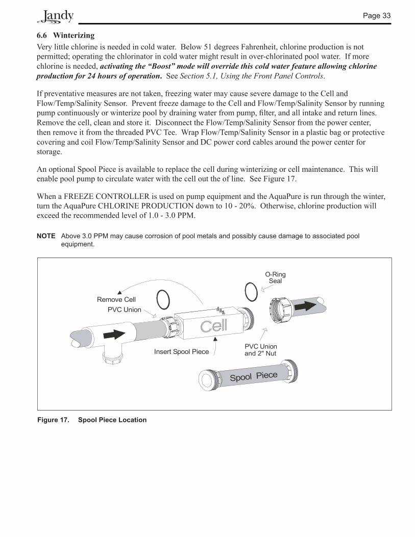
Figure 17. Spool Piece Location
6.6 WinterizingVery little chlorine is needed in cold water. Below 51 degrees Fahrenheit, chlorine production is not permitted; operating the chlorinator in cold water might result in over-chlorinated pool water. If more chlorine is needed, activating the “Boost” mode will override this cold water feature allowing chlorine production for 24 hours of operation. See Section 5.1, Using the Front Panel Controls.
If preventative measures are not taken, freezing water may cause severe damage to the Cell and Flow/Temp/Salinity Sensor. Prevent freeze damage to the Cell and Flow/Temp/Salinity Sensor by running pumpcontinuouslyorwinterizepoolbydrainingwaterfrompump,filter,andallintakeandreturnlines.Remove the cell, clean and store it. Disconnect the Flow/Temp/Salinity Sensor from the power center, then remove it from the threaded PVC Tee. Wrap Flow/Temp/Salinity Sensor in a plastic bag or protective covering and coil Flow/Temp/Salinity Sensor and DC power cord cables around the power center for storage.
An optional Spool Piece is available to replace the cell during winterizing or cell maintenance. This will enable pool pump to circulate water with the cell out the of line. See Figure 17.
When a FREEZE CONTROLLER is used on pump equipment and the AquaPure is run through the winter, turn the AquaPure CHLORINE PRODUCTION down to 10 - 20%. Otherwise, chlorine production will exceed the recommended level of 1.0 - 3.0 PPM.
NOTE Above 3.0 PPM may cause corrosion of pool metals and possibly cause damage to associated pool equipment.
Page 3�
Section 7. Troubleshooting
NOTE: Turn off power to unit prior to attempting service or repair.
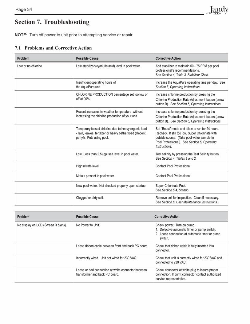
7.1 Problems and Corrective Action
Problem Possible Cause Corrective Action
Low or no chlorine. Low stabilizer (cyanuric acid) level in pool water. Add stabilizer to maintain 50 - 75 PPM per pool professional’s recommendations. See Section 4, Table 3, Stabilizer Chart.
Insufficient operating hours of the AquaPure unit.
Increase the AquaPure operating time per day. See Section 5, Operating Instructions.
CHLORINE PRODUCTION percentage set too low or off at 00%.
Increase chlorine production by pressing the Chlorine Production Rate Adjustment button (arrow button B). See Section 5, Operating Instructions.
Recent increases in weather temperature without increasing the chlorine production of your unit.
Increase chlorine production by pressing the Chlorine Production Rate Adjustment button (arrow button B). See Section 5, Operating Instructions.
Temporary loss of chlorine due to heavy organic load - rain, leaves, fertilizer or heavy bather load (Recent party!). Pets using pool.
Set “Boost” mode and allow to run for 24 hours. Recheck. If still too low, Super Chlorinate with outside source. (Take pool water sample to Pool Professional). See Section 5, Operating Instructions.
Low (Less than 2.5) gpl salt level in pool water. Test salinity by pressing the Test Salinity button. See Section 4, Tables 1 and 2.
High nitrate level. Contact Pool Professional.
Metals present in pool water. Contact Pool Professional.
New pool water. Not shocked properly upon startup. Super Chlorinate Pool. See Section 5.4, Startup.
Clogged or dirty cell. Remove cell for inspection. Clean if necessary. See Section 6, User Maintenance Instructions.
Problem Possible Cause Corrective Action
No display on LCD (Screen is blank). No Power to Unit. Check power. Turn on pump. 1. Defective automatic timer or pump switch. 2. Loose connection at automatic timer or pump switch.
Loose ribbon cable between front and back PC board. Check that ribbon cable is fully inserted into connector.
Incorrectly wired. Unit not wired for 230 VAC. Check that unit is correctly wired for 230 VAC and connected to 230 VAC.
Loose or bad connection at white connector between transformer and back PC board.
Check connector at white plug to insure proper connection. If burnt connector contact authorized service representative.
Page 35
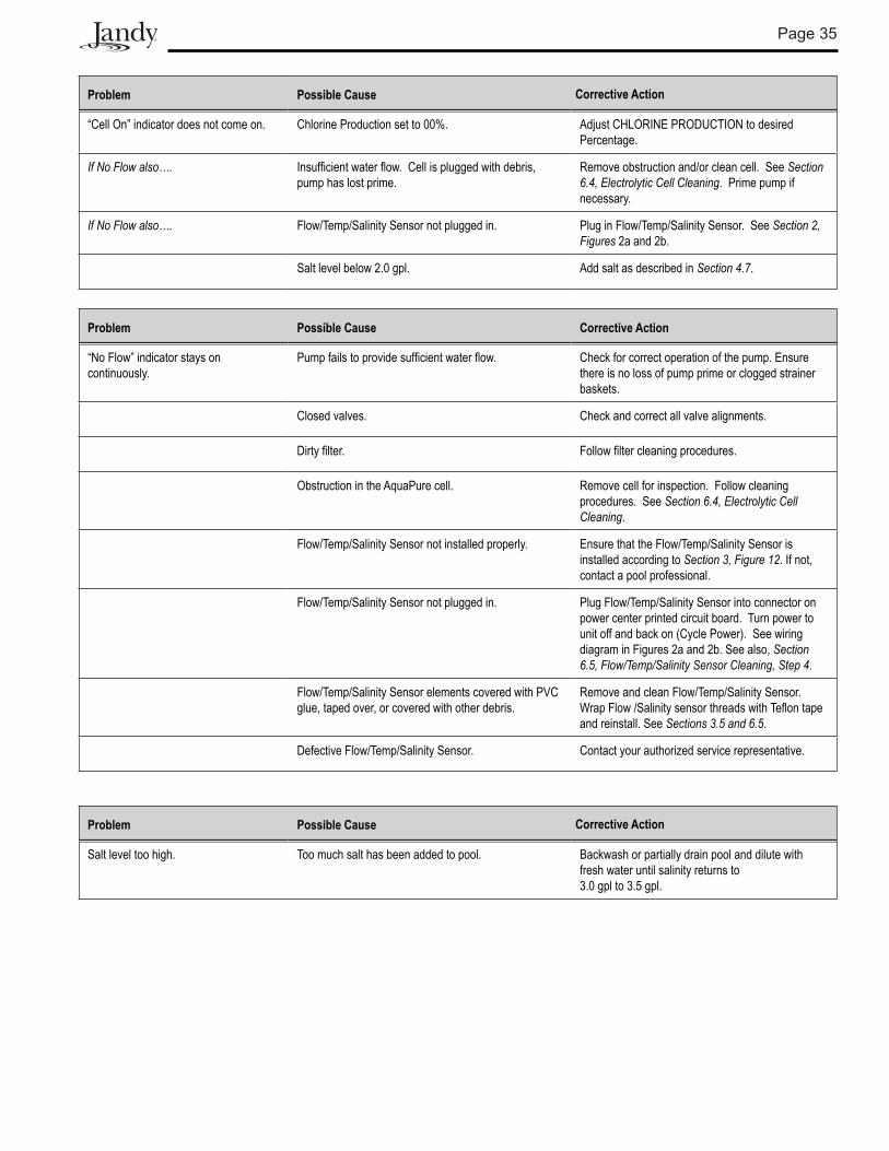
Problem Possible Cause Corrective Action
“Cell On” indicator does not come on. Chlorine Production set to 00%. Adjust CHLORINE PRODUCTION to desired Percentage.
If No Flow also…. Insufficient water flow. Cell is plugged with debris, pump has lost prime.
Remove obstruction and/or clean cell. See Section 6.4, Electrolytic Cell Cleaning. Prime pump if necessary.
If No Flow also…. Flow/Temp/Salinity Sensor not plugged in. Plug in Flow/Temp/Salinity Sensor. See Section 2, Figures 2a and 2b.
Salt level below 2.0 gpl. Add salt as described in Section 4.7.
Problem Possible Cause Corrective Action
“No Flow” indicator stays on continuously.
Pump fails to provide sufficient water flow. Check for correct operation of the pump. Ensure there is no loss of pump prime or clogged strainer baskets.
Closed valves. Check and correct all valve alignments.
Dirty filter. Follow filter cleaning procedures.
Obstruction in the AquaPure cell. Remove cell for inspection. Follow cleaning procedures. See Section 6.4, Electrolytic Cell Cleaning.
Flow/Temp/Salinity Sensor not installed properly. Ensure that the Flow/Temp/Salinity Sensor is installed according to Section 3, Figure 12. If not, contact a pool professional.
Flow/Temp/Salinity Sensor not plugged in. Plug Flow/Temp/Salinity Sensor into connector on power center printed circuit board. Turn power to unit off and back on (Cycle Power). See wiring diagram in Figures 2a and 2b. See also, Section 6.5, Flow/Temp/Salinity Sensor Cleaning, Step 4.
Flow/Temp/Salinity Sensor elements covered with PVC glue, taped over, or covered with other debris.
Remove and clean Flow/Temp/Salinity Sensor. Wrap Flow /Salinity sensor threads with Teflon tape and reinstall. See Sections 3.5 and 6.5.
Defective Flow/Temp/Salinity Sensor. Contact your authorized service representative.
Problem Possible Cause Corrective Action
Salt level too high. Too much salt has been added to pool. Backwash or partially drain pool and dilute with fresh water until salinity returns to 3.0 gpl to 3.5 gpl.
Page 36
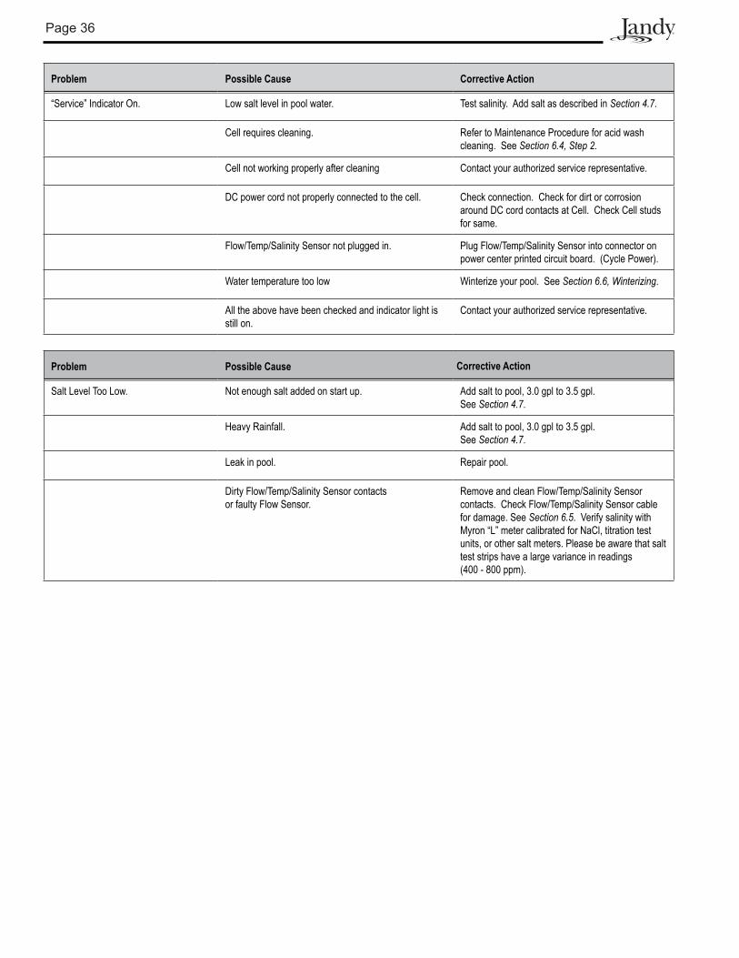
Problem Possible Cause Corrective Action
“Service” Indicator On. Low salt level in pool water. Test salinity. Add salt as described in Section 4.7.
Cell requires cleaning. Refer to Maintenance Procedure for acid wash cleaning. See Section 6.4, Step 2.
Cell not working properly after cleaning Contact your authorized service representative.
DC power cord not properly connected to the cell. Check connection. Check for dirt or corrosion around DC cord contacts at Cell. Check Cell studs for same.
Flow/Temp/Salinity Sensor not plugged in. Plug Flow/Temp/Salinity Sensor into connector on power center printed circuit board. (Cycle Power).
Water temperature too low Winterize your pool. See Section 6.6, Winterizing.
All the above have been checked and indicator light is still on.
Contact your authorized service representative.
Problem Possible Cause Corrective Action
Salt Level Too Low. Not enough salt added on start up. Add salt to pool, 3.0 gpl to 3.5 gpl. See Section 4.7.
Heavy Rainfall. Add salt to pool, 3.0 gpl to 3.5 gpl. See Section 4.7.
Leak in pool. Repair pool.
Dirty Flow/Temp/Salinity Sensor contacts or faulty Flow Sensor.
Remove and clean Flow/Temp/Salinity Sensor contacts. Check Flow/Temp/Salinity Sensor cable for damage. See Section 6.5. Verify salinity with Myron “L” meter calibrated for NaCl, titration test units, or other salt meters. Please be aware that salt test strips have a large variance in readings (400 - 800 ppm).
Page 37
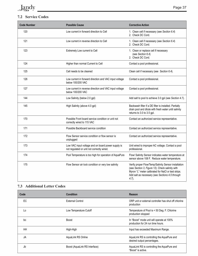
7.2 Service Codes
Code Number Possible Cause Corrective Action
120 Low current in forward direction to Cell 1. Clean cell if necessary (see Section 6.4) 2. Check DC Cord.
121 Low current in reverse direction to Cell 1. Clean cell if necessary (see Section 6.4) 2. Check DC Cord.
123 Extremely Low current to Cell 1. Clean or replace cell if necessary (see Section 6.4) 2. Check DC Cord.
124 Higher than normal Current to Cell Contact a pool professional.
125 Cell needs to be cleaned Clean cell if necessary (see Section 6.4).
126 Low current in forward direction and VAC input voltage below 100/200 VAC
Contact a pool professional.
127 Low current in reverse direction and VAC input voltage below 100/200 VAC
Contact a pool professional.
144 Low Salinity (below 2.0 gpl) Add salt to pool to achieve 3.0 gpl (see Section 4.7).
145 High Salinity (above 4.0 gpl) Backwash filter if a DE filter is installed. Partially drain pool and dilute with fresh water until salinity returns to 3.0 to 3.5 gpl.
170 Possible Front board service condition or unit not correctly wired to 115 VAC
Contact an authorized service representative.
171 Possible Backboard service condition Contact an authorized service representative.
172 Flow Sensor service condition or flow sensor is unplugged
Contact an authorized service representative.
173 Low VAC input voltage and on board power supply is not regulated or unit not correctly wired.
Unit wired to improper AC voltage. Contact a pool professional.
174 Pool Temperature is too high for operation of AquaPure Flow/ Salinity Sensor indicates water temperature at sensor above 108 F. Reduce water temperature.
175 Flow Sensor air lock condition or very low salinity Verify proper Flow/Temp/Salinity Sensor installation (see Section 3, Figure 12). Check salinity with Myron “L” meter calibrated for NaCl or test strips. Add salt as necessary (see Sections 4.5 through 4.7).
7.3 Additional Letter Codes
Code Condition Reason
EC External Control ORP unit or external controller has shut off chlorine production
Lo Low Temperature Cutoff Temperature of Pool is < 50 Deg. F. Chlorine production stopped
bo Boost In “Boost” mode unit will operate at 100% production for 24 run time hours.
HH High-High Input has exceeded Maximum Range.
JA AquaLink RS Online AquaLink RS is controlling the AquaPure and desired output percentages.
Jb Boost (AquaLink RS Interface) AquaLink RS is controlling the AquaPure and “Boost” is active.
Page 38
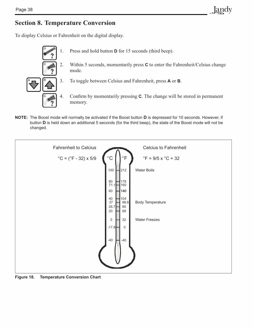
Section 8. Temperature Conversion
To display Celsius or Fahrenheit on the digital display.
1. Press and hold button D for 15 seconds (third beep).
2. Within 5 seconds, momentarily press C to enter the Fahrenheit/Celsius change mode.
3. To toggle between Celsius and Fahrenheit, press A or B.
4. ConfirmbymomentarilypressingC. The change will be stored in permanent memory.
NOTE: The Boost mode will normally be activated if the Boost button D is depressed for 10 seconds. However, if button D is held down an additional 5 seconds (for the third beep), the state of the Boost mode will not be changed.
-40
-17.8
20
0
37
60
80
100
-40
0
32
8098.6
160
212
17671.1
140
26.768
140
10440
°F°C
Water Boils
Body Temperature
Water Freezes
Fahrenheit to Celcius
°C = (°F - 32) x 5/9
Celcius to Fahrenheit
°F = 9/5 x °C + 32
Figure 18. Temperature Conversion Chart
Page 39
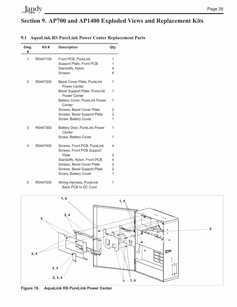
Section 9. AP700 and AP1400 Exploded Views and Replacement Kits
9.1 AquaLink RS PureLink Power Center Replacement Parts
Dwg.#
Kit # Description Qty.
1 R0447100 Front PCB, PureLinkSupport Plate, Front PCBStandoffs, NylonScrews
11�6
2 R0447200 Bezel Cover Plate, PureLink Power CenterBezel Support Plate, PureLink Power CenterBattery Cover, PureLink Power CenterScrews, Bezel Cover PlateScrews, Bezel Support PlateScrew, Battery Cover
1
1
1
221
3 R0447300 Battery Door, PureLink Power CenterScrew, Battery Cover
1
1
� R0447400 Screws, Front PCB, PureLinkScrews, Front PCB Support PlateStandoffs, Nylon, Front PCBScrews, Bezel Cover PlateScrews, Bezel Support PlateScrew, Battery Cover
� 2�221
5 R0447500 Wiring Harness, PureLink Back PCB to DC Cord
1
1
1, 4
2
2, 3, 4
2, 3
1, 4
2, 4
2, 4
5
1, 4
Figure 19. AquaLink RS PureLink Power Center
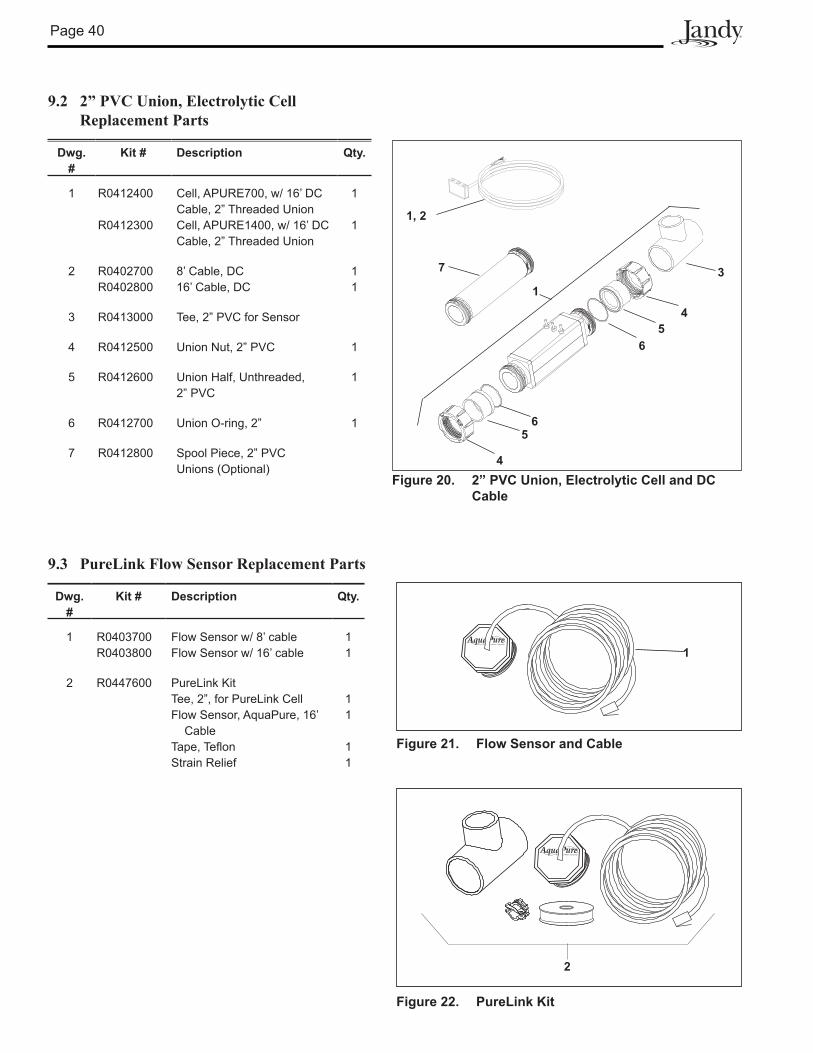
Page �0
9.2 2” PVC Union, Electrolytic Cell Replacement Parts
Dwg.#
Kit # Description Qty.
1 R0412400
R0412300
Cell, APURE700, w/ 16’ DC Cable, 2” Threaded Union Cell, APURE1400, w/ 16’ DC Cable, 2” Threaded Union
1
1
2 R0402700R0402800
8’ Cable, DC16’ Cable, DC
11
3 R0413000 Tee, 2” PVC for Sensor
� R0412500 Union Nut, 2” PVC 1
5 R0412600 Union Half, Unthreaded, 2” PVC
1
6 R0412700 Union O-ring, 2” 1
7 R0412800 Spool Piece, 2” PVC Unions (Optional)
1
Figure 21. Flow Sensor and Cable
9.3 PureLink Flow Sensor Replacement Parts
Dwg.#
Kit # Description Qty.
1 R0403700R0403800
Flow Sensor w/ 8’ cableFlow Sensor w/ 16’ cable
11
2 R0447600 PureLink KitTee, 2”, for PureLink CellFlow Sensor, AquaPure, 16’ CableTape, TeflonStrain Relief
11
11
13
1, 2
4
4
5
5
6
6
Figure 20. 2” PVC Union, Electrolytic Cell and DC Cable
7
2
Figure 22. PureLink Kit

Page 41
Notes

Page 42
Notes

Page �3

LIMITED WARRANTYThank you for purchasing Jandy® pool and spa products. Jandy Pool Products, Inc. warrants all parts to be freefrom manufacturing defects in materials and workmanship for a period of one year from the date of retail purchase, with the following exceptions:
• AquaLink® RS units installed with Jandy Surge Protection Kits will be covered for two years.• NeverLube® valves are warranted for the life of pool and/or spa on which they were originally installed.• AquaPureTM Electronic Chlorine Generator Electrolytic Cells carry a 5 year limited warranty on a prorated basis.
This warranty is limited to the first retail purchaser, is not transferable, and does not apply to products that have been moved from their original installation sites. The liability of Jandy Pool Products, Inc. shall not exceed the repair or replacement of defective parts and does not include any costs for labor to remove and reinstall the defective part, transportation to or from the factory, and any other materials required to make the repair. This warranty does not cover failures or malfunctions resulting from the following:
1. Failure to properly install, operate or maintain the product(s) in accordance with our published Installation,Operation and Maintenance Manuals provided with the product(s).
2. The workmanship of any installer of the product(s).3. Not maintaining a proper chemical balance in your pool and/or spa [pH level between 7.2 and 7.8, Total
Alkalinity (TA) between 80 to 120 ppm, Total Dissolved Solids (TDS) less than 2000 not including salt ppm].4. Abuse, alteration, accident, fire, flood, lightning, rodents, insects, negligence or acts of God.5. Scaling, freezing, or other conditions causing inadequate water circulation.6. Operating the product(s) at water flow rates outside the published minimum and maximum specifications.7. Use of non-factory authorized parts or accessories in conjunction with the product(s).8. Chemical contamination of combustion air or improper use of sanitizing chemicals, such as introducing
sanitizing chemicals upstream of the heater and cleaner hose or through the skimmer.9. Overheating; incorrect wire runs; improper electrical supply; collateral damage caused by failure of O-Rings,
DE grids, or cartridge elements; or damage caused by running the pump with insufficient quantities of water.
LIMITATION OF LIABILITY:This is the only warranty given by Jandy Pool Products, Inc. No one is authorized to make any other warranties on behalf of Jandy Pool Products, Inc. THIS WARRANTY IS IN LIEU OF ALL OTHER WARRANTIES, EXPRESSED OR IMPLIED, INCLUDING BUT NOT LIMITED TO ANY IMPLIED WARRANTIES OF FITNESS FOR A PARTICULAR PURPOSE AND MERCHANTABILITY. JANDY POOL PRODUCTS, INC. EXPRESSLY DISCLAIMS AND EXCLUDES ANY LIABILITY FOR CONSEQUENTIAL, INCIDENTAL, INDIRECT OR PUNITIVE DAMAGES FOR BREACH OF ANY EXPRESSED OR IMPLIED WARRANTY. This warranty gives you specific legal rights. You may also have other rights which vary by state or province.
WARRANTY CLAIMS:For prompt warranty consideration, contact your dealer and provide the following information: proof of purchase, model number, serial number and date of installation. The installer will contact the factory for instructions regarding the claim and to determine the location of the nearest designated service center. If the dealer is not available, you can locate a service center in your area by visiting www.jandy.com or by calling our technical support department at (707) 776-8200 extension 260. All returned parts must have a Returned Material Authorization number to be evaluated under the terms of this warranty.
6000 Condor Drive • Moorpark, CA USA 93021 • 707.776.8200 • Fax 707.763.7785Litho in U.S.A. © Waterpik Technologies 0401
Jandy Pool Products, Inc.
H05
7350
0-
Litho in U.S.A. © Jandy Pool Products, Inc. 0511