Embed Size (px)
Citation preview
Jandy® AquaLink® RS & AquaLink PDAMain power center board (PCB) Replacement Kit
These instructions are to be used with the following Jandy Replacement Kits:
R04685xx -- AquaLink RS Upgrade AssemblyR05865xx -- Aqualink PDA Upgrade AssemblyR0466700 -- AquaLink RS & PDA Main Power Center Board AssemblyR04668xx -- AquaLink RS, CPU BoardR05861xx -- Aqualink PDA, CPU Board
WARNINGFOR YOUR SAFETY: This product must be installed and serviced by a professional pool/spa service technician. The procedures in this instruction sheet must be followed exactly. Ensure that all electrical power to the system is turned off before approaching, inspecting or troubleshooting any leaking valves that may have caused other electrical devices in the surrounding area to get wet. Failure to do so could result in an electrical hazard which could result in death or serious injury due to electrical shock, and may also cause damage to property. Improper installation and/or operation will void the warranty.
1. Introduction
This document gives instructions for replacing the PCB and the CPU of the Jandy AquaLink Power Center. Before starting this procedure, use the parts list of each kit to identify the parts that are in your kit. If any parts are missing from the kit, please call your local Jandy distributor for assistance. For technical assistance, please contact our Technical Support Department at (800) 822-7933. These instructions must be followed exactly. Read through the instructions completely before starting the procedure. Please save these instructions.
WARNINGIf the information in these instructions is not followed exactly, an electrical fire or shock hazard may result causing property damage, personal injury or death.
2. Replacement of the Main Power Center Board (PCB)
WARNINGRisk of Electric Shock which can result In Serious Injury or Death. Before attempting installation or service, ensure that all power to the circuit supplying power to the system is disconnected or turned off at the circuit breaker. All wiring must be done in accordance with the National Electric Code® (NEC®), NFPA 70®. In Canada, the Canadian Electrical Code (CEC), CSA C22.1, must be followed. All applicable local installation codes and regulations must be followed.
1. Before replacing the main power center board, go to the Controller and review the current settings. Then record all settings on the Programming and Settings Worksheet provided at the back of these instructions.
2. Turn off all power to the power center.
3. Open the door to the power center.
H02
9370
0_R
EV
B
Page 2 Jandy® | AquaLink® RS/PDA Power Center PCB and CPU Replacement Kits
4. Replace the main power center board in model 6613 or 6614 as follows:
a. Remove the top two (2) screws that secure the cover plate to the power center. Remove the cover plate as shown in Figure 1.
5. Replace the Main power center board in model 6613AP or 6614AP as follows:
a. Remove the two (2) screws from faceplate as shown in Figure 2, and fold down the faceplate/bezel assembly to access the back of the main power center board.
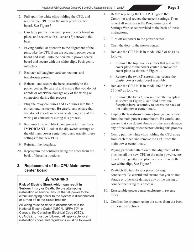
Figure 3. CPU PCB Bezel Assembly
6. Unplug the connectors from the red, black, and green terminal bars located on the main power center board. Be careful and ensure that you do not abrade or otherwise damage any of the wiring or connectors during this process.
7. Before unplugging the relay coil wires or JVA wires, note which socket each relay coil wire or JVA wire is plugged into. Unplug the relay and JVA connectors.
8. Remove the two screws that secure the plastic power center bezel assembly.
9. Unplug the transformer power (orange connector) and any daughter card connections from the bezel. Remove the bezel from the power center. Be careful and ensure that you do not abrade or otherwise damage any of the wiring or connectors during this process.
10. Lay the bezel face down on the pink anti-static packaging from the replacement PCB kit.
11. Remove all seven (7) screws that secure the PCB to the bezel.
CAUTIONTo avoid damages caused by static electricity, handle the PCB by its edges only. Avoid touching any electronics components with your fingertips. Do not replace the PCB in the rain.
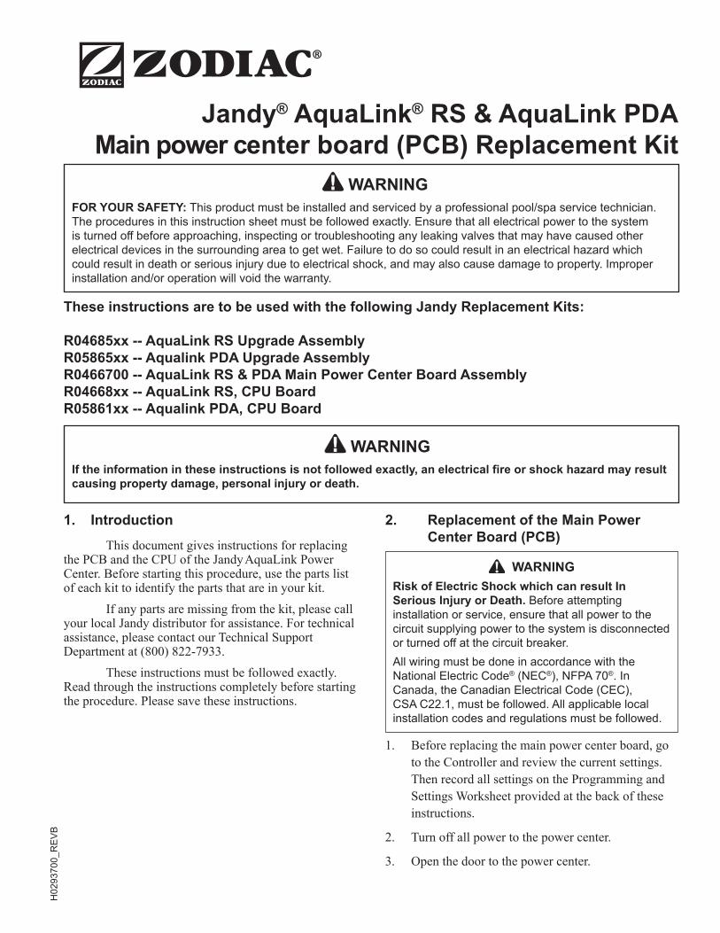
AquaLink RS & PDAMain Power Center Board
Cover PlateScrews
Figure 1. Power Center Model 6613/6614
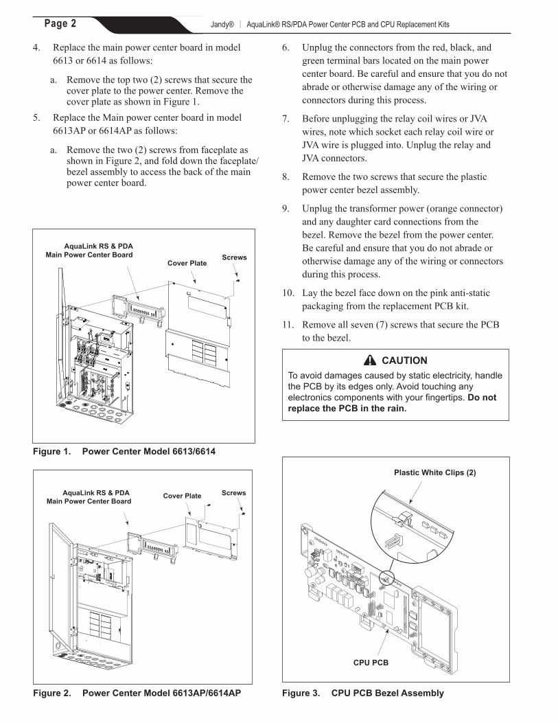
Cover PlateAquaLink RS & PDA Main Power Center Board
Screws
Figure 2. Power Center Model 6613AP/6614AP
Plastic White Clips (2)
CPU PCB
24VAC
J24
Page 3AquaLink® RS/PDA Power Center PCB and CPU Replacement Kits | Jandy®
12. Pull apart the white clips holding the CPU, and remove the CPU from the main power center board. See Figure 3.
13. Carefully put the new main power center board in place, and secure with all seven (7) screws to the bezel.
14. Paying particular attention to the alignment of the pins, take the CPU from the old main power center board and install into the new main power center board and secure with the white clips. Push gently into place.
15. Reattach all daughter card connections and transformer power.
16. Reinstall and secure the bezel assembly to the power center. Be careful and ensure that you do not abrade or otherwise damage any of the wiring or connectors during this process.
17. Plug the relay coil wires and JVA wires into their corresponding sockets. Be careful and ensure that you do not abrade or otherwise damage any of the wiring or connectors during this process.
18. Reconnect the red, black, and green terminal bars. IMPORTANT: Look at the dip switch settings on the old main power center board and transfer these settings to the new PCB.
19. Reinstall the faceplate.
20. Reprogram the controller using the notes from the back of these instructions.
3. Replacement of the CPU Main power center board
WARNINGRisk of Electric Shock which can result In Serious Injury or Death. Before attempting installation or service, ensure that all power to the circuit supplying power to the system is disconnected or turned off at the circuit breaker. All wiring must be done in accordance with the National Electric Code® (NEC®), NFPA 70®. In Canada, the Canadian Electrical Code (CEC), CSA C22.1, must be followed. All applicable local installation codes and regulations must be followed.
1. Before replacing the CPU PCB, go to the Controller and review the current settings. Then record all settings on the Programming and Settings Worksheet provided at the back of these instructions.
2. Turn off all power to the power center.
3. Open the door to the power center.
4. Replace the CPU PCB in model 6613 or 6614 as follows:
a. Remove the top two (2) screws that secure the cover plate to the power center. Remove the cover plate as shown in Figure 1.
b. Remove the two (2) screws that secure the plastic power center bezel assembly.
5. Replace the CPU PCB in model 6613AP or 6614AP as follows:
a. Remove the two (2) screws from the faceplate as shown in Figure 2, and fold down the faceplate/bezel assembly to access the back of the main power center board.
6. Unplug the transformer power (orange connector) from the main power center board. Be careful and ensure that you do not abrade or otherwise damage any of the wiring or connectors during this process.
7. Gently pull the white clips holding the CPU away from each other, and remove the CPU from the main power center board.
8. Paying particular attention to the alignment of the pins, install the new CPU to the main power center board. Push gently into place and secure with the two white clips. See Figure 3.
9. Reattach the transformer power (orange connector). Be careful and ensure that you do not abrade or otherwise damage any of the wiring or connectors during this process.
10. Reassemble power center enclosure in reverse order.
11. Confirm the program using the notes from the back of these instructions.
Zodiac Pool Systems, Inc. 2620 Commerce Way, Vista, CA 92081 1.800.822.7933 | www.ZodiacPoolSystems.com
ZODIAC® is a registered trademark of Zodiac International, S.A.S.U., used under license. All trademarks referenced herein are the property of their respective owners.
©2014 Zodiac Pool Systems, Inc. H0293700_REVB
Page 4AquaLink® RS/PDA Power Center PCB and CPU Replacement Kits | Jandy®
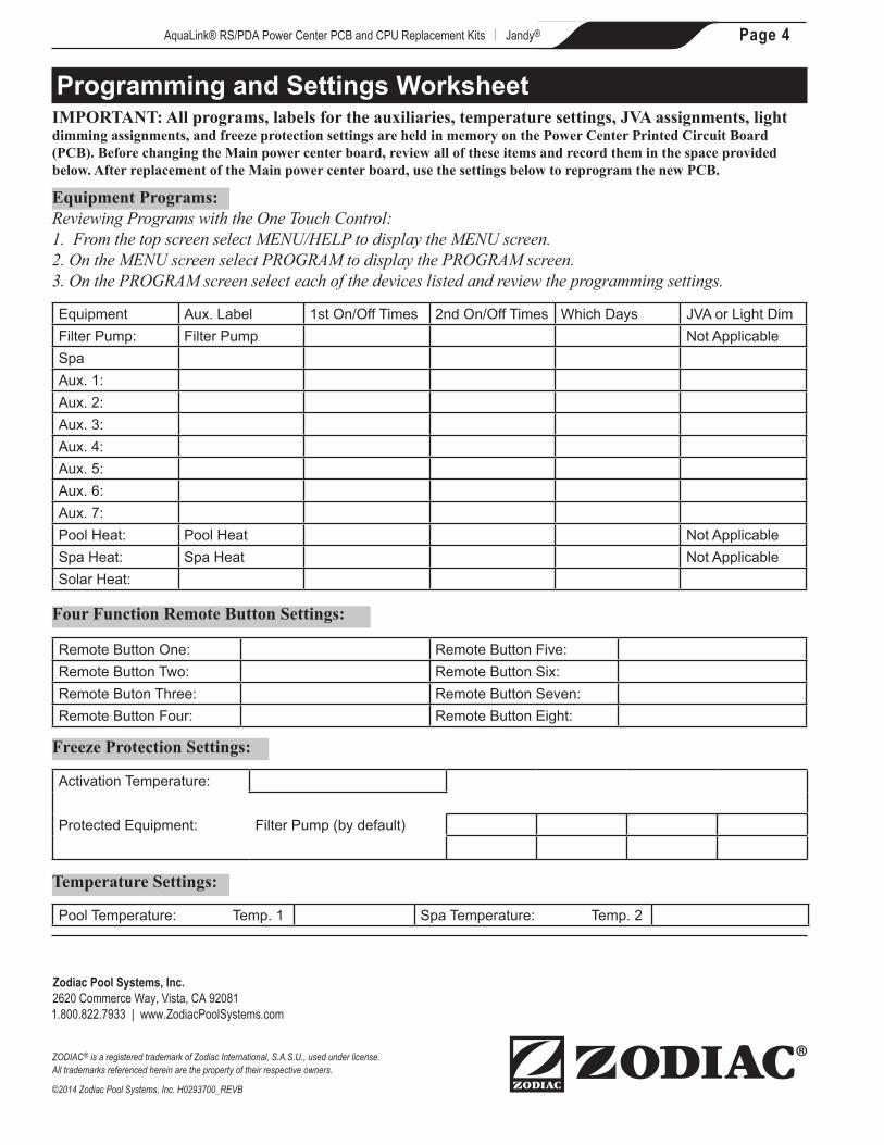
Programming and Settings WorksheetIMPORTANT: All programs, labels for the auxiliaries, temperature settings, JVA assignments, light dimming assignments, and freeze protection settings are held in memory on the Power Center Printed Circuit Board (PCB). Before changing the Main power center board, review all of these items and record them in the space provided below. After replacement of the Main power center board, use the settings below to reprogram the new PCB.
Equipment Programs:Reviewing Programs with the One Touch Control:1. From the top screen select MENU/HELP to display the MENU screen.2. On the MENU screen select PROGRAM to display the PROGRAM screen.3. On the PROGRAM screen select each of the devices listed and review the programming settings.
Four Function Remote Button Settings:
Temperature Settings:
Freeze Protection Settings:
Equipment Aux. Label 1st On/Off Times 2nd On/Off Times Which Days JVA or Light DimFilter Pump: Filter Pump Not ApplicableSpaAux. 1:Aux. 2:Aux. 3:Aux. 4:Aux. 5:Aux. 6:Aux. 7:Pool Heat: Pool Heat Not ApplicableSpa Heat: Spa Heat Not ApplicableSolar Heat:
Remote Button One: Remote Button Five:Remote Button Two: Remote Button Six:Remote Buton Three: Remote Button Seven:Remote Button Four: Remote Button Eight:
Activation Temperature:
Protected Equipment: Filter Pump (by default)
Pool Temperature: Temp. 1 Spa Temperature: Temp. 2