Embed Size (px)
Citation preview
Sonoma Raceway Ohio Idaho
p 415.489.0866 www.CortexXracing.com
© CorteX Precision Technology 2009-2020 All Rights Reserved v0 Page 1 of 11
Installation Instructions
2005-2014 S197 Mustang K-Member and Front Lower
Control Arms
FSS-40-2000
2005-2014 Mustang, All
Including Convertible
Congratulations on your purchase of a CorteX Xtreme-Grip Suspension products. Through professional engineering and extensive testing both on the street and racetracks like Sonoma Raceway (Sears Point), and Thunder Hill, and Laguna Seca with record setting cars, we’ve created a system that will deliver unsurpassed handling with minimal modification to your Mustang. After the installation is complete you will only be limited by tire choice and your own skills as a driver. We wish you much success! While the Xtreme-Grip suspension package is designed to be minimally invasive, due to the technical nature and specialized equipment required, professional installation is recommended. Go to www.CorteXracing.com for a list of approved installers. CorteX engineers suspension systems designed for ease of installation, we do not install or guarantee proper installation. If you choose to attempt installation of the system yourself, please carefully review these instructions to determine whether you have the tools and experience necessary before beginning disassembly. A factory Ford service manual should also be consulted for disassembly/reassembly details and Original Equipment Manufacturer (OEM) bolt torque specifications. For technical assistance or questions please call CorteX Precision Technology; 415.489.0866
© CorteX Precision Technology 2009-2020 All Rights Reserved v0 Page 2 of 11
Contents
Getting Started .............................................................................................................................................. 3
K-member Installation ................................................................................................................................. 4
APPENDICES .................................................................................................................................................. 7
APPENDIX A: Xtreme-Grip K-member Assembly for Strut Cars ............................................................... 7
APPENDIX B: Alignment Specs ............................................................................................................... 11
© CorteX Precision Technology 2009-2020 All Rights Reserved v0 Page 3 of 11
CAUTION: Installation of the Xtreme-Grip suspension package requires working under your Mustang.
It is the responsibility of the installer to ensure a safe working environment. The use of an automotive lift is recommended, though installation is possible with use of floor jacks. In either case, always ensure that the vehicle is safely supported with multiple jack stands, and always wear appropriate safety gear and safety glasses.
Warning: Incorrect alignment settings can cause erratic handling and excessive tire wear therefore a
professional alignment is necessary after installing the Xtreme-Grip K-member and adjustable lower control arms.
Getting Started
TECHNICAL NOTE: When installing full suspension kit, installation should always be performed beginning
with the rear suspension followed by the front suspension.
Recommended Tools
Automotive lift
Adjustable bottle jack
Engine Support beam (under hood), MMT-11
Floor Jack
Jack stands
Impact wrench
Appropriate Sockets with ratchet
Appropriate Box end wrench
The CorteX Xtreme-Grip K-Member is compatible with both the 05-10 Hydraulic power steering rack
or the 11-14 electric EPAS steering rack.
We recommend our bumpsteer kit CBS-40-1000 be used with the K-member because the control arms
are equipped with drop ball joints and the K-member has multiple control arm position for further roll
center compensation. All of these factors will changes in the bumpsteer that can be tuned out with by
using the bumpsteer kit.
© CorteX Precision Technology 2009-2020 All Rights Reserved v0 Page 4 of 11
1. Support the engine inside the engine compartment using an available engine support beam such
as MMT-11 so that the motor mounts can be disconnected.
2. Place vehicle on chassis lift. If a lift is unavailable, then raise vehicle with floor jacks and support
unibody at lifting points specified in the Ford service manual. Using a lift for this installation is
highly encouraged.
3. Remove the factory subframe with the lower control arms from the vehicle. We recommend
leaving the struts, spindles, sway bar, brakes, etc intact since they do not need be removed.
4. Do not use an impact wrench to assembly any of the CorteX components as it can result in over-
torqueing critical hardware. Always use a high-quality calibrated torque wrench.
K-member Installation
1. Read the “Getting Started” Instruction Section and complete tasks 1-4.
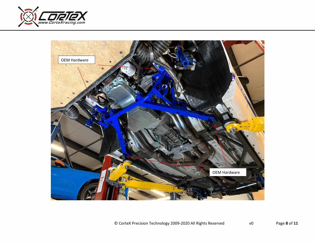
2. Reinstall the CorteX Xtreme-Grip K-member on the vehicle chassis using the OEM hardware.
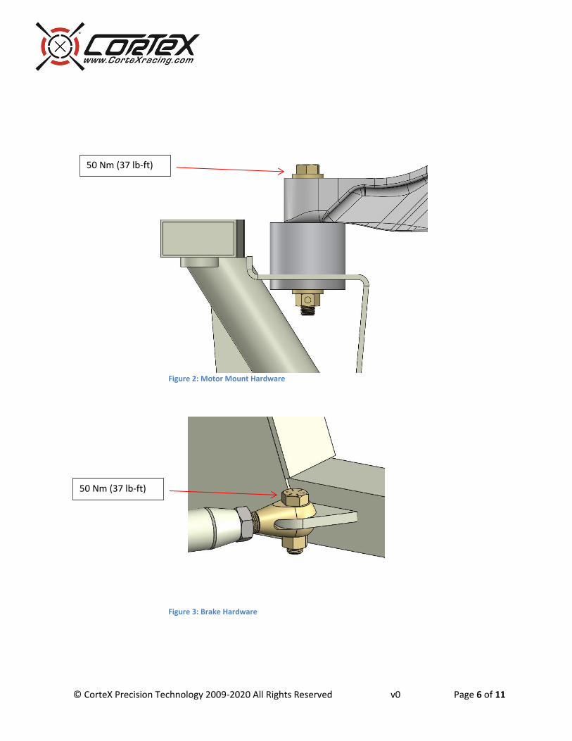
3. Insert either solid motor mounts or rubber isolator biscuits between the K-member mounting pads and the Ford factory engine block brackets (Figure 2). Use the included hardware.
4. Set the lower control arm to closely match the length OEM control arm length. Also adjust the aluminum strut to position the ball joint at approximately the same for/aft position of the OEM ball joint. Torque the bolt that attached the control arm to the values shown in Figure 1.
5. Install the CorteX lower control arms using the included hardware.
6. Reattached the spindles to the ball joints
7. Reinstall the steering rack onto the k-member.
8. Install the diagonal brace onto the K-member and torque bolt as shown in Figure 3.
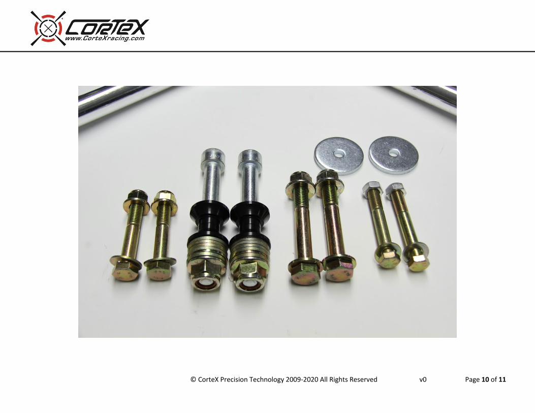
9. Figures 1, 2, 3 show fastener torque specifications. Appendix A shows all included parts.
10. Reinstall vehicle undertray if equipped.
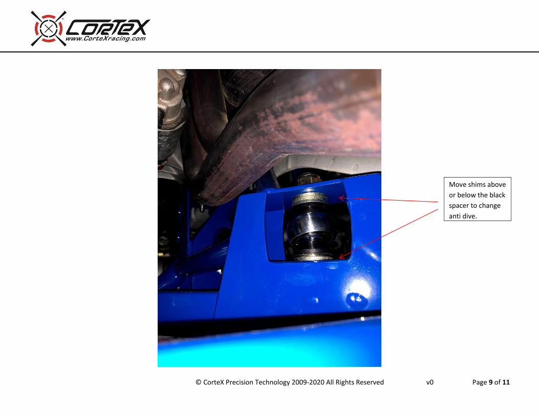
11. The lower control arm is adjustable for length, roll center, and antidive.
© CorteX Precision Technology 2009-2020 All Rights Reserved v0 Page 5 of 11
a. We recommend setting the length of the control arm to closely match the OEM arm length. If desired, the arm can be lengthened which will increase camber.
b. Changing the length of the aluminum strut will add or subtract caster. It is essential that the bolt attaching the strut to the control arm body is loosened while adjusting the caster link. Changing the length of that link requires a small amount of rotation around that bolt.
c. Raising the front pivot location of the control arm at the k-member will raise the roll center. The bottom hole is the OEM position.
d. Raising the rear mounting position relative to the front will increase antidive. e. When in doubt start with the neutral geometry as close to the OEM geometry as
possible. Most street cars will not need the alternate control arm mounting point since the arm is already equipped with drop ball joints.
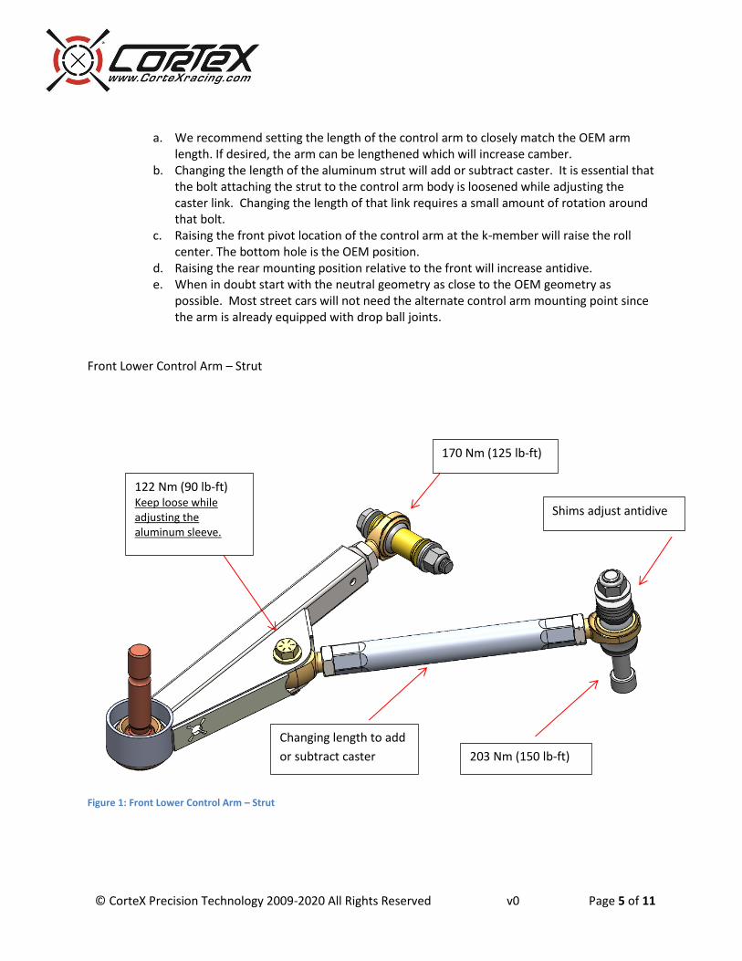
Front Lower Control Arm – Strut
Figure 1: Front Lower Control Arm – Strut
170 Nm (125 lb-ft)
203 Nm (150 lb-ft)
122 Nm (90 lb-ft) Keep loose while adjusting the aluminum sleeve.
Changing length to add
or subtract caster
Shims adjust antidive
© CorteX Precision Technology 2009-2020 All Rights Reserved v0 Page 6 of 11
Figure 2: Motor Mount Hardware
Figure 3: Brake Hardware
50 Nm (37 lb-ft)
50 Nm (37 lb-ft)
© CorteX Precision Technology 2009-2020 All Rights Reserved v0 Page 7 of 11
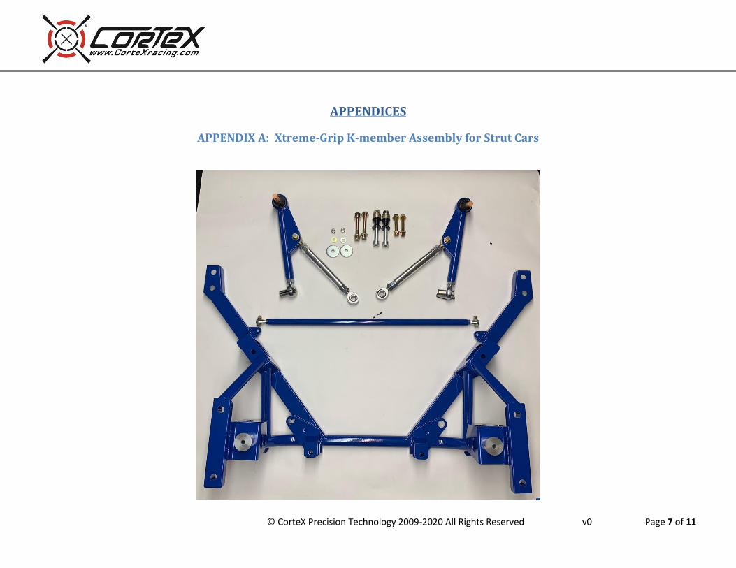
APPENDICES
APPENDIX A: Xtreme-Grip K-member Assembly for Strut Cars
© CorteX Precision Technology 2009-2020 All Rights Reserved v0 Page 8 of 11
OEM Hardware
OEM Hardware
© CorteX Precision Technology 2009-2020 All Rights Reserved v0 Page 9 of 11
Move shims above
or below the black
spacer to change
anti dive.
© CorteX Precision Technology 2009-2020 All Rights Reserved v0 Page 10 of 11
© CorteX Precision Technology 2009-2020 All Rights Reserved v0 Page 11 of 11
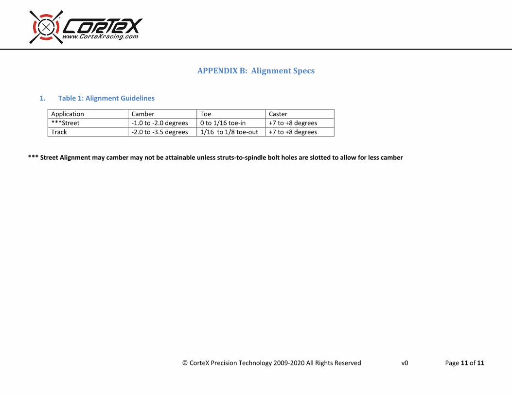
APPENDIX B: Alignment Specs
1. Table 1: Alignment Guidelines
Application Camber Toe Caster
***Street -1.0 to -2.0 degrees 0 to 1/16 toe-in +7 to +8 degrees
Track -2.0 to -3.5 degrees 1/16 to 1/8 toe-out +7 to +8 degrees
*** Street Alignment may camber may not be attainable unless struts-to-spindle bolt holes are slotted to allow for less camber