Embed Size (px)
Citation preview

Copyright ©
Page - 1 - of 46
254D1001 Installation Instructions, Rev 1.07
Mini Cooper S Supercharger replacement system
SPRINTEX® MINI Cooper S
SUPERCHARGER REPLACEMENT SYSTEM
254A1001
INSTALLATION INSTRUCTIONS
Kit Serial # _____________________________________________
Supercharger Serial # _______________________________________
ECU Serial # _____________________________________________
Copyright ©
Page - 2 - of 46
254D1001 Installation Instructions, Rev 1.07
Mini Cooper S Supercharger replacement system
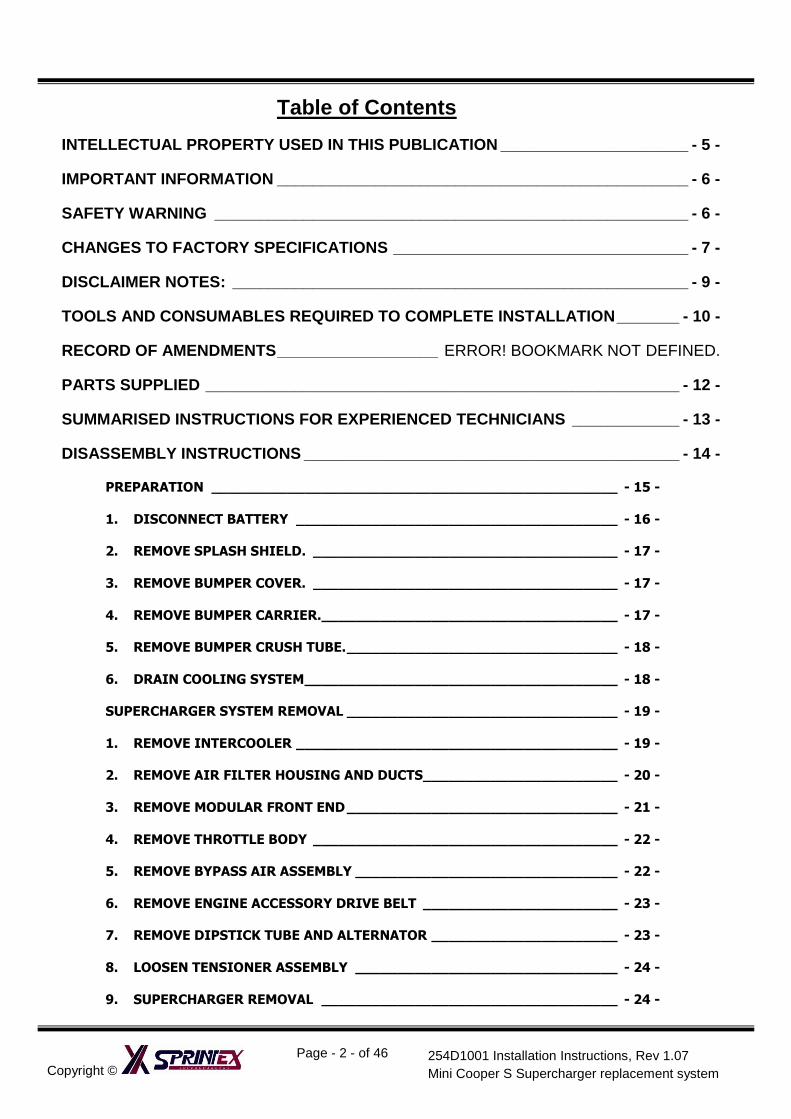
Table of Contents
INTELLECTUAL PROPERTY USED IN THIS PUBLICATION _____________________ - 5 -
IMPORTANT INFORMATION ______________________________________________ - 6 -
SAFETY WARNING _____________________________________________________ - 6 -
CHANGES TO FACTORY SPECIFICATIONS _________________________________ - 7 -
DISCLAIMER NOTES: ___________________________________________________ - 9 -
TOOLS AND CONSUMABLES REQUIRED TO COMPLETE INSTALLATION _______ - 10 -
RECORD OF AMENDMENTS __________________ ERROR! BOOKMARK NOT DEFINED.
PARTS SUPPLIED _____________________________________________________ - 12 -
SUMMARISED INSTRUCTIONS FOR EXPERIENCED TECHNICIANS ____________ - 13 -
DISASSEMBLY INSTRUCTIONS __________________________________________ - 14 -
PREPARATION ________________________________________________ - 15 -
1. DISCONNECT BATTERY ______________________________________ - 16 -
2. REMOVE SPLASH SHIELD. ____________________________________ - 17 -
3. REMOVE BUMPER COVER. ____________________________________ - 17 -
4. REMOVE BUMPER CARRIER.___________________________________ - 17 -
5. REMOVE BUMPER CRUSH TUBE. ________________________________ - 18 -
6. DRAIN COOLING SYSTEM _____________________________________ - 18 -
SUPERCHARGER SYSTEM REMOVAL ________________________________ - 19 -
1. REMOVE INTERCOOLER ______________________________________ - 19 -
2. REMOVE AIR FILTER HOUSING AND DUCTS_______________________ - 20 -
3. REMOVE MODULAR FRONT END ________________________________ - 21 -
4. REMOVE THROTTLE BODY ____________________________________ - 22 -
5. REMOVE BYPASS AIR ASSEMBLY _______________________________ - 22 -
6. REMOVE ENGINE ACCESSORY DRIVE BELT _______________________ - 23 -
7. REMOVE DIPSTICK TUBE AND ALTERNATOR ______________________ - 23 -
8. LOOSEN TENSIONER ASSEMBLY _______________________________ - 24 -
9. SUPERCHARGER REMOVAL ___________________________________ - 24 -
Copyright ©
Page - 3 - of 46
254D1001 Installation Instructions, Rev 1.07
Mini Cooper S Supercharger replacement system
INSTALLATION INSTRUCTIONS __________________________________________ - 25 -
PREPARATION BEFORE ASSEMBLY _________________________________ - 26 -
ASSEMBLY ____________________________________________________ - 29 -
1. FIT TENSIONER ASSEMBLY ___________________________________ - 29 -
2. FIT SUPERCHARGER _________________________________________ - 29 -
3. FIT KNOCK SENSOR _________________________________________ - 30 -
4. FIT ALTERNATOR ___________________________________________ - 30 -
5. FIT DIPSTICK TUBE _________________________________________ - 30 -
6. FIT DRIVE BELT ____________________________________________ - 31 -
7. FIT INTAKE ASSEMBLY _______________________________________ - 33 -
8. FIT BREATHER AND VACUUM LINES ____________________________ - 33 -
9. FIT WATER PUMP ___________________________________________ - 34 -
10. PLUG IN ELECTRICAL COMPONENTS __________________________ - 34 -
11. WATER PUMP RELAY HARNESS ______________________________ - 35 -
12. WATER PUMP RELAY MOUNTING _____________________________ - 35 -
13. WATER PUMP WIRING CONNECTIONS. ________________________ - 35 -
14. FIT RADIATOR HOSES _____________________________________ - 36 -
15. FIT THROTTLE BODY ______________________________________ - 36 -
16. FIT INLET AIR HOSE _______________________________________ - 36 -
17. FIT AIR BOX ASSEMBLY AND ENGINE CONTROL UNIT _____________ - 37 -
18. FIT INTERCOOLER ASSEMBLY _______________________________ - 37 -
19. FIT MODULAR FRONT END __________________________________ - 37 -
20. FIT FRONT BUMPER CARRIER. _______________________________ - 38 -
21. RECONNECT BATTERY _____________________________________ - 39 -
22. FILL AND BLEED COOLANT SYSTEM. __________________________ - 39 -
23. FIT FRONT BUMPER COVER _________________________________ - 41 -
PRE TEST-DRIVE INSPECTION __________________________________________ - 42 -
1. PRE-START INSPECTION _____________________________________ - 43 -
ENGINE WARM UP _____________________________________________ - 43 -
Copyright ©
Page - 4 - of 46
254D1001 Installation Instructions, Rev 1.07
Mini Cooper S Supercharger replacement system
ROAD TEST VEHICLE ____________________________________________ - 43 -
MAINTENANCE INSTRUCTIONS __________________________________________ - 44 -
1. SUPERCHARGER DRIVE BELT REPLACEMENT ______________________ - 45 -
3. SUPERCHARGER REMOVAL ___________________________________ - 46 -
4. SUPERCHARGER LUBRICATION SERVICE_________________________ - 46 -
Copyright ©
Page - 5 - of 46
254D1001 Installation Instructions, Rev 1.07
Mini Cooper S Supercharger replacement system
Intellectual Property used in this Publication
This document is copyright of Sprintex Ltd, a company incorporated in Australia. This document may not be re-sold, copied or distributed in any way without prior written authorisation of a director of Sprintex Ltd.
Copyrights / Trademarks: Sprintex® is a registered trademark of Sprintex Limited, an Australian company ACN: 106 337 599 (“Sprintex”). Sprintex has patents for its superchargers. Any unauthorised copying or modification of the system may result in legal action. Loctite® and Grey Maxx® are a registered trademark of Henkel KGaA, a company incorporated in Germany. Other than commercial supply arrangements, Henkel KGaA do not have any association with Sprintex®.
RedLine® is a registered trademark of RedLine Synthetic Oil Corporation, a company incorporated in United States of America. Other than commercial supply arrangements, Redline and RedLine Synthetic Oil Corporation do not have any association with Sprintex®. Mini, Mini Cooper S, Mini Cooper are registered trademarks of BMW AG Motor Co, a company Headquartered in Munich, Germany ( http://www.bmw.com ) SAE is a trademark of SAE International (www.sae.org), global technology information and standards setting resource organisation for the design, manufacturing, operation, and maintenance industry. Gates is a registered trademark of the Gates Rubber Company, a subsidiary of Tomkins Plc, incorporated in London, United Kingdom. Other than commercial supply arrangements, Gates and Tomkins Plc do not have any association with Sprintex Limited.
Copyright ©
Page - 6 - of 46
254D1001 Installation Instructions, Rev 1.07
Mini Cooper S Supercharger replacement system
IMPORTANT INFORMATION
PRODUCT WARNING
Installation of the Sprintex Supercharger kit on your Mini Cooper S vehicle may void all or parts of Mini Warranty. Customers should consult their Mini dealer for details. Sprintex makes no representation that installation and use of the Sprintex supercharger kit is legal for public road use worldwide. Customers should check that installation and use of the Sprintex supercharger kit on their vehicle is legal by contacting the relevant statutory authority in their jurisdiction prior to use on roads.
Sprintex supports safe driving. So always remember to observe all speed limits and road rules relevant to your state, city or jurisdiction.
Provided in this installation manual are detailed instructions to the installer on how to install the Sprintex patent pending supercharger kit to the Mini Cooper S vehicle. The instructions are aimed at being simple yet informative, and are aided
with well-presented pictures to make installations as simple, fast, and problem free as possible. Please read the entire instruction manual prior to beginning the installation procedure. Pictures and descriptions may vary
slightly from model to model. It is recommended that all wiring harness connectors, and vacuum hoses are labelled at the time of removal for easy and correct refitting. Some components that are removed and are to be refitted are fragile, and should be stored safely to prevent damage to these components. Sprintex recommends performing the following vehicle checks prior to installing the supercharger.
1) Check that the factory fuel system is operating correctly. 2) Inspect the factory exhaust catalyst for blocks or damage 3) Check fuel quality in fuel tank ensuring that it is not stale or low octane fuel. Replace with a higher Octane, Premium Unleaded Gasoline / Fuel (Refer details on the next page) as required. It is also recommended to replace the fuel filter if the vehicle has travelled more than 15,000km or 9000 miles.
Sprintex will not be liable for any loss, damage, payment, costs, expenses or other liability, not expressly stated in this document. In particular, Sprintex shall not be liable to any person for any consequential, indirect or economic loss or punitive or exemplary damages of any kind. Sprintex reserves the right to change specifications from time to time and will not be liable to any person for doing so. Sprintex believes that information in this document is correct at time of print. Sprintex limits its liability to the maximum extent permissible at law with regard to the reliance which any person places on anything in this document.
THIS SPRINTEX INSTALLATION REQUIRES THAT YOUR VEHICLE BE FITTED WITH A STANDARD MINI COOPER S FACTORY ECU AND CALIBRATION. FAILURE TO ENSURE THIS WILL AFFECT THE PERFORMANCE AND MAY VOID YOUR WARRANTY. SHOULD YOU BE UNSURE, RETURN YOUR MOTOR VEHICLE TO YOUR NEAREST MINI DEALER TO ENSURE THE STANDARD CALIBRATION HAS BEEN REINSTATED AND IS OPERATING CORRECTLY.
SAFETY WARNING No unauthorised service or alteration may be undertaken to the Sprintex supercharger. Installation should be carried out in a workshop which is a safe and ventilated working environment with equipment and procedures compliant with local authority guidelines and legal requirements. Installers should ensure adequate hearing, eye, and physical protection is used at all times during the installation process. Installers should take reasonable precautions to avoid fatigue and closely follow the installation instructions during every installation. Sprintex recommends installation should not be carried out unsupervised. Sprintex, its directors, employees and agents will not accept liability for damage accident or injury resulting from the installation process. Safety warnings are also provided throughout this document.
Copyright ©
Page - 7 - of 46
254D1001 Installation Instructions, Rev 1.07
Mini Cooper S Supercharger replacement system
CHANGES TO FACTORY SPECIFICATIONS
FUEL: MINIMUM 95 OCTANE PREMIUM UNLEADED GASOLINE/FUEL TO BE USED AT ALL TIMES.
NEVER ALLOW THE ENGINE TO KNOCK OR DETONATE AS SERIOUS ENGINE DAMAGE MAY
OCCUR.
China Minimum 93 OCTANE Premium Unleaded Gasoline / Fuel USA Minimum 93 OCTANE Premium Unleaded Gasoline / Fuel
Europe Minimum 95 RON Premium Unleaded Petrol Australia Minimum 95 RON Premium Unleaded Petrol New Zealand Minimum 95 RON Premium Unleaded Petrol
REQUIRED SERVICE: (SEE MAINTENANCE SECTION OF MANUAL)
1. INSPECT SUPERCHARGER DRIVE BELT AT EVERY ROUTINE SERVICE AND REPLACE
WHEN REQUIRED.
2. DRAIN AND REPLACE SUPERCHARGER OIL EVERY 50,000km (30,000 miles) or 2 YEARS
(whichever is earlier).
3. USE 111ml (3.75 US fluid ounces) of REDLINE 75W90NS HIGH PERFORMANCE GEAR OIL.
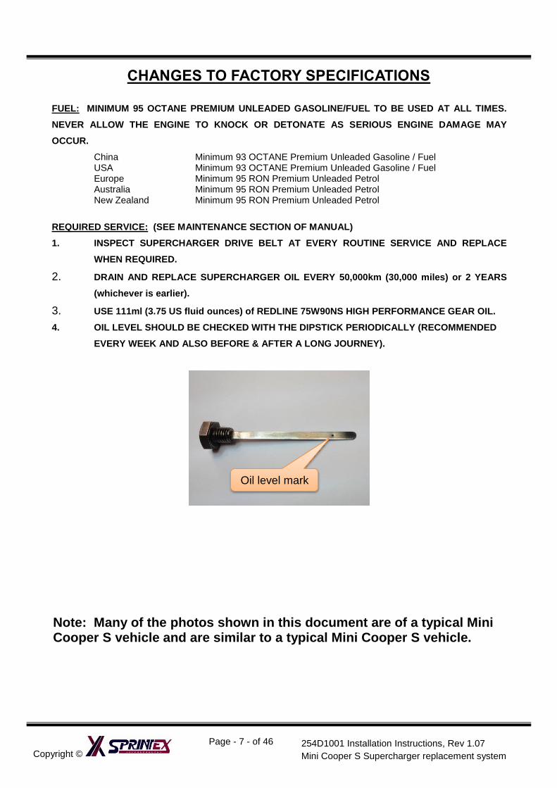
4. OIL LEVEL SHOULD BE CHECKED WITH THE DIPSTICK PERIODICALLY (RECOMMENDED
EVERY WEEK AND ALSO BEFORE & AFTER A LONG JOURNEY).
Note: Many of the photos shown in this document are of a typical Mini Cooper S vehicle and are similar to a typical Mini Cooper S vehicle.
Oil level mark
Copyright ©
Page - 8 - of 46
254D1001 Installation Instructions, Rev 1.07
Mini Cooper S Supercharger replacement system
*** WARNING ***
You must load the CARB Calibration File into the Mini’s ECU using the Bytetronik FA-LITE Tuning module in order for this Sprintex upgrade to be CARB Compliant and street legal. Please refer to the Bytetronik Tuning Module for additional instructions.
Failure to do so will cause your Sprintex upgrade to be NON-CARB compliant and not legal for use on public roads in the USA. You will also be at significant risk of damaging your motor if you do not load this file before operating the engine with the supercharger installed.
*** WARNING ***
Refer FA-LITE Tuning Module (For MINI Cooper R50/R52/R53) installation manual, if supplied with the Supercharger kit or contact Bytetronik. Email: [email protected] www.bytetronik.com
Copyright ©
Page - 9 - of 46
254D1001 Installation Instructions, Rev 1.07
Mini Cooper S Supercharger replacement system
Disclaimer notes:
“This Sprintex Supercharger System carries CARB exemption Executive Order D-695 when installed to a standard R52 or R53 Mini Cooper in accordance with the instructions contained herein. Sprintex will not be responsible for any failure to meet CARB or EPA specifications caused by incorrect or incomplete installation of the parts supplied or by the condition and or specification of the host vehicle.”
‘The CARB EO decal supplied must not be applied to a vehicle that is modified in any way for any reason other than by installation of the Sprintex Parts supplied, installed in accordance with the instructions and recommendations contained herein.’
Copyright ©
Page - 10 - of 46
254D1001 Installation Instructions, Rev 1.07
Mini Cooper S Supercharger replacement system
Tools and Consumables Required to Complete Installation
Metric Wrenches and Socket
sets
Cable Ties Top-up coolant
Flat and Philips Screwdrivers Electrical Tape Metric Allen keys
Solder and Soldering Gun Sealant, thread locker Rubber grease
Pliers and Side Cutters Top-up Engine Oil Clip remover
Copyright ©
Page - 11 - of 46
254D1001 Installation Instructions, Rev 1.07
Mini Cooper S Supercharger replacement system
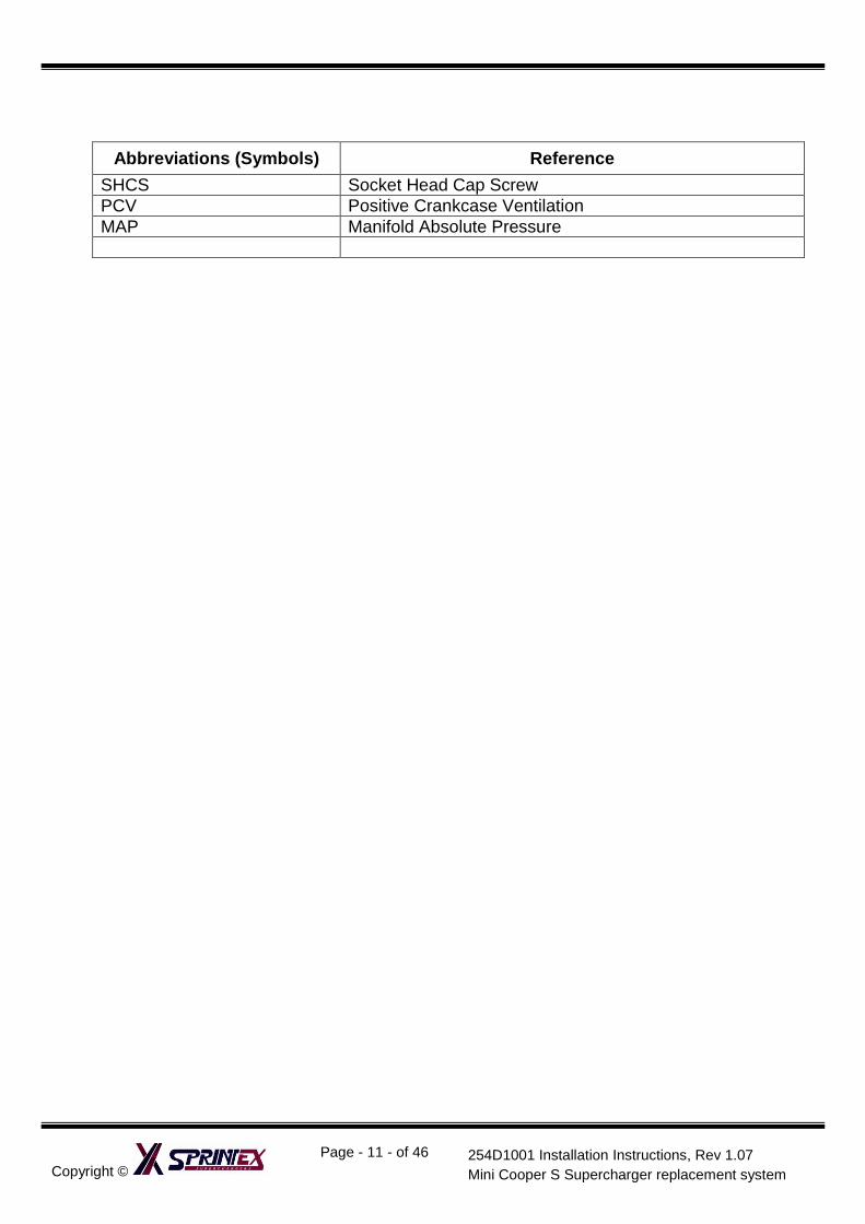
Abbreviations (Symbols) Reference
SHCS Socket Head Cap Screw
PCV Positive Crankcase Ventilation
MAP Manifold Absolute Pressure

Copyright ©
Page - 12 - of 46
254D1001 Installation Instructions, Rev 1.07
Mini Cooper S Supercharger replacement system
PARTS SUPPLIED
1. Sprintex® Supercharger assembly
2. Drive Belt Tensioner assembly
3. Discharge Duct
4. Intake Pipe
5. Water Pump assembly
6. Water Pump Wiring Loom
7. Ancillary parts
8. Drive belt
9. Tensioner Tool
10. Limit gauge for belt tensioner
11. Installation Manual
12. Bytetronik FA-LITE Tuning Module (for
MINI Cooper R50/R52/R53) kit
(OPTIONAL)
1 2 3
4 5 6 7 8 9 10
11
Copyright ©
Page - 13 - of 46
254D1001 Installation Instructions, Rev 1.07
Mini Cooper S Supercharger replacement system
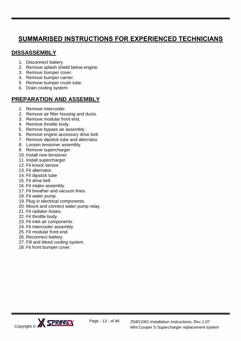
SUMMARISED INSTRUCTIONS FOR EXPERIENCED TECHNICIANS
DISSASSEMBLY
1. Disconnect battery 2. Remove splash shield below engine. 3. Remove bumper cover. 4. Remove bumper carrier. 5. Remove bumper crush tube. 6. Drain cooling system.
PREPARATION AND ASSEMBLY
1. Remove intercooler. 2. Remove air filter housing and ducts. 3. Remove modular front end. 4. Remove throttle body. 5. Remove bypass air assembly. 6. Remove engine accessory drive belt. 7. Remove dipstick tube and alternator. 8. Loosen tensioner assembly. 9. Remove supercharger. 10. Install new tensioner. 11. Install supercharger. 12. Fit knock sensor. 13. Fit alternator. 14. Fit dipstick tube 15. Fit drive belt 16. Fit intake assembly. 17. Fit breather and vacuum lines. 18. Fit water pump. 19. Plug in electrical components. 20. Mount and connect water pump relay. 21. Fit radiator hoses. 22. Fit throttle body. 23. Fit inlet air components. 24. Fit intercooler assembly 25. Fit modular front end. 26. Reconnect battery. 27. Fill and bleed cooling system. 28. Fit front bumper cover.
Copyright ©
Page - 14 - of 46
254D1001 Installation Instructions, Rev 1.07
Mini Cooper S Supercharger replacement system
MINI COOPER S SUPERCHARGER REPLACEMENT
SYSTEM
SECTION 1
DISASSEMBLY INSTRUCTIONS
SAFETY WARNING No unauthorised service or alteration may be undertaken to the Sprintex supercharger. Installation should be carried out in a workshop which is a safe and ventilated working environment with equipment and procedures compliant with local authority guidelines and legal requirements. Installers should ensure adequate hearing, eye, and physical protection is used at all times during the installation process. Installers should take reasonable precautions to avoid fatigue and closely follow the installation instructions during every installation. Sprintex recommends installation should not be carried out unsupervised. Sprintex, its directors, employees and agents will not accept liability for damage accident or injury resulting from the installation process. Safety warnings are also provided throughout this document.
MINI COOPER S SUPERCHARGER KIT DISASSEMBLY PROCEDURES
Copyright ©
Page - 15 - of 46
254D1001 Installation Instructions, Rev 1.07
Mini Cooper S Supercharger replacement system
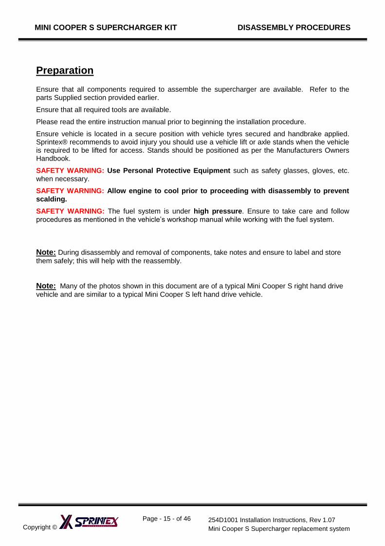
Preparation Ensure that all components required to assemble the supercharger are available. Refer to the parts Supplied section provided earlier.
Ensure that all required tools are available.
Please read the entire instruction manual prior to beginning the installation procedure.
Ensure vehicle is located in a secure position with vehicle tyres secured and handbrake applied. Sprintex® recommends to avoid injury you should use a vehicle lift or axle stands when the vehicle is required to be lifted for access. Stands should be positioned as per the Manufacturers Owners Handbook.
SAFETY WARNING: Use Personal Protective Equipment such as safety glasses, gloves, etc. when necessary.
SAFETY WARNING: Allow engine to cool prior to proceeding with disassembly to prevent scalding.
SAFETY WARNING: The fuel system is under high pressure. Ensure to take care and follow procedures as mentioned in the vehicle’s workshop manual while working with the fuel system.
Note: During disassembly and removal of components, take notes and ensure to label and store
them safely; this will help with the reassembly.
Note: Many of the photos shown in this document are of a typical Mini Cooper S right hand drive
vehicle and are similar to a typical Mini Cooper S left hand drive vehicle.
MINI COOPER S SUPERCHARGER SYSTEM INSTALLATION PROCEDURES
Copyright ©
Page - 16 - of 46
254D1001 Installation Instructions, Rev 1.07
Mini Cooper S Supercharger replacement system
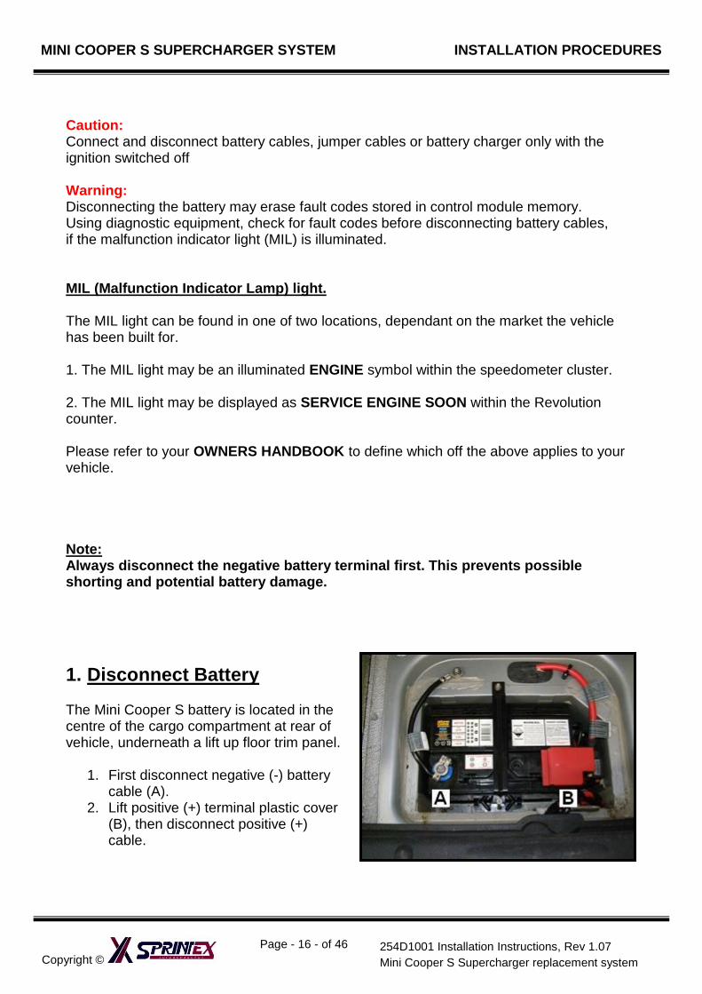
Caution: Connect and disconnect battery cables, jumper cables or battery charger only with the ignition switched off Warning: Disconnecting the battery may erase fault codes stored in control module memory. Using diagnostic equipment, check for fault codes before disconnecting battery cables, if the malfunction indicator light (MIL) is illuminated. MIL (Malfunction Indicator Lamp) light. The MIL light can be found in one of two locations, dependant on the market the vehicle has been built for. 1. The MIL light may be an illuminated ENGINE symbol within the speedometer cluster. 2. The MIL light may be displayed as SERVICE ENGINE SOON within the Revolution counter. Please refer to your OWNERS HANDBOOK to define which off the above applies to your vehicle. Note: Always disconnect the negative battery terminal first. This prevents possible shorting and potential battery damage.
1. Disconnect Battery The Mini Cooper S battery is located in the centre of the cargo compartment at rear of vehicle, underneath a lift up floor trim panel.
1. First disconnect negative (-) battery cable (A).
2. Lift positive (+) terminal plastic cover (B), then disconnect positive (+) cable.
MINI COOPER S SUPERCHARGER SYSTEM INSTALLATION PROCEDURES
Copyright ©
Page - 17 - of 46
254D1001 Installation Instructions, Rev 1.07
Mini Cooper S Supercharger replacement system
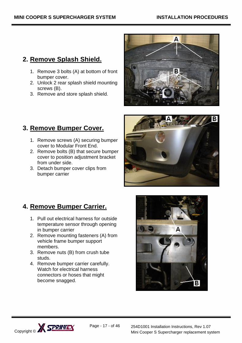
2. Remove Splash Shield.
1. Remove 3 bolts (A) at bottom of front bumper cover.
2. Unlock 2 rear splash shield mounting screws (B).
3. Remove and store splash shield.
3. Remove Bumper Cover.
1. Remove screws (A) securing bumper cover to Modular Front End.
2. Remove bolts (B) that secure bumper cover to position adjustment bracket from under side.
3. Detach bumper cover clips from bumper carrier
4. Remove Bumper Carrier.
1. Pull out electrical harness for outside temperature sensor through opening in bumper carrier
2. Remove mounting fasteners (A) from vehicle frame bumper support members.
3. Remove nuts (B) from crush tube studs.
4. Remove bumper carrier carefully. Watch for electrical harness connectors or hoses that might become snagged.
MINI COOPER S SUPERCHARGER SYSTEM INSTALLATION PROCEDURES
Copyright ©
Page - 18 - of 46
254D1001 Installation Instructions, Rev 1.07
Mini Cooper S Supercharger replacement system
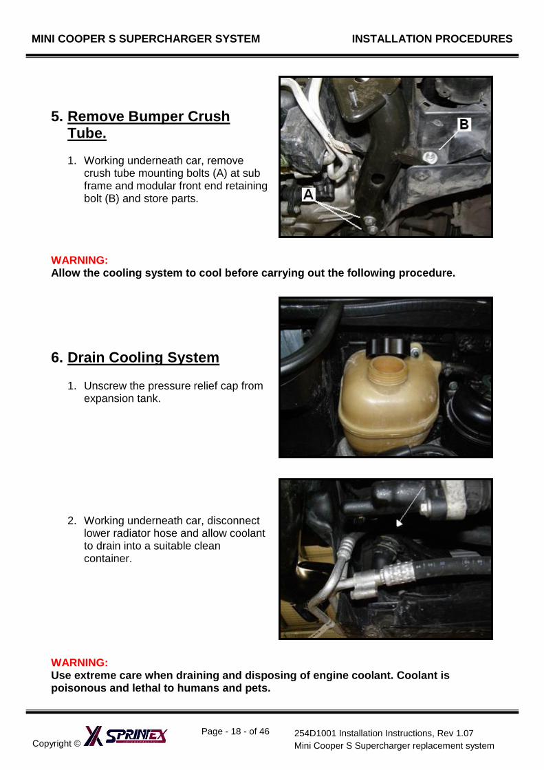
5. Remove Bumper Crush Tube.
1. Working underneath car, remove
crush tube mounting bolts (A) at sub frame and modular front end retaining bolt (B) and store parts.
WARNING: Allow the cooling system to cool before carrying out the following procedure.
6. Drain Cooling System
1. Unscrew the pressure relief cap from expansion tank.
2. Working underneath car, disconnect lower radiator hose and allow coolant to drain into a suitable clean container.
WARNING: Use extreme care when draining and disposing of engine coolant. Coolant is poisonous and lethal to humans and pets.
MINI COOPER S SUPERCHARGER SYSTEM INSTALLATION PROCEDURES
Copyright ©
Page - 19 - of 46
254D1001 Installation Instructions, Rev 1.07
Mini Cooper S Supercharger replacement system
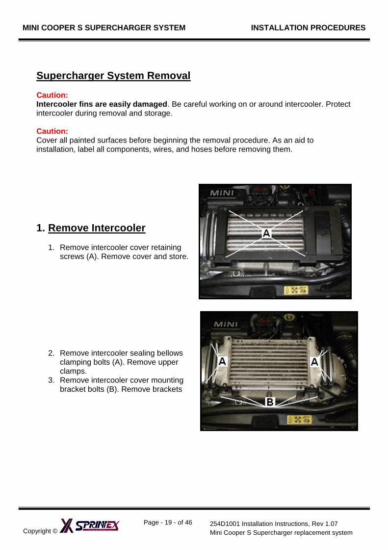
Supercharger System Removal Caution: Intercooler fins are easily damaged. Be careful working on or around intercooler. Protect intercooler during removal and storage. Caution: Cover all painted surfaces before beginning the removal procedure. As an aid to installation, label all components, wires, and hoses before removing them.
1. Remove Intercooler
1. Remove intercooler cover retaining screws (A). Remove cover and store.
2. Remove intercooler sealing bellows clamping bolts (A). Remove upper clamps.
3. Remove intercooler cover mounting bracket bolts (B). Remove brackets
MINI COOPER S SUPERCHARGER SYSTEM INSTALLATION PROCEDURES
Copyright ©
Page - 20 - of 46
254D1001 Installation Instructions, Rev 1.07
Mini Cooper S Supercharger replacement system
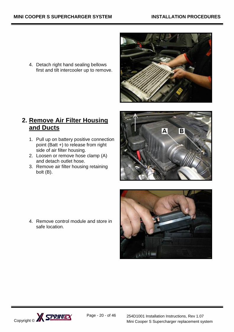
4. Detach right hand sealing bellows first and tilt intercooler up to remove.
2. Remove Air Filter Housing and Ducts
1. Pull up on battery positive connection
point (Batt +) to release from right side of air filter housing.
2. Loosen or remove hose clamp (A) and detach outlet hose.
3. Remove air filter housing retaining bolt (B).
4. Remove control module and store in safe location.
MINI COOPER S SUPERCHARGER SYSTEM INSTALLATION PROCEDURES
Copyright ©
Page - 21 - of 46
254D1001 Installation Instructions, Rev 1.07
Mini Cooper S Supercharger replacement system
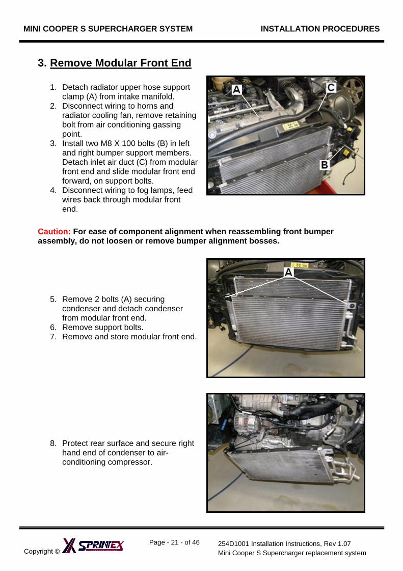
3. Remove Modular Front End
1. Detach radiator upper hose support clamp (A) from intake manifold.
2. Disconnect wiring to horns and radiator cooling fan, remove retaining bolt from air conditioning gassing point.
3. Install two M8 X 100 bolts (B) in left and right bumper support members. Detach inlet air duct (C) from modular front end and slide modular front end forward, on support bolts.
4. Disconnect wiring to fog lamps, feed wires back through modular front end.
Caution: For ease of component alignment when reassembling front bumper assembly, do not loosen or remove bumper alignment bosses.
5. Remove 2 bolts (A) securing condenser and detach condenser from modular front end.
6. Remove support bolts. 7. Remove and store modular front end.
8. Protect rear surface and secure right hand end of condenser to air-conditioning compressor.
MINI COOPER S SUPERCHARGER SYSTEM INSTALLATION PROCEDURES
Copyright ©
Page - 22 - of 46
254D1001 Installation Instructions, Rev 1.07
Mini Cooper S Supercharger replacement system
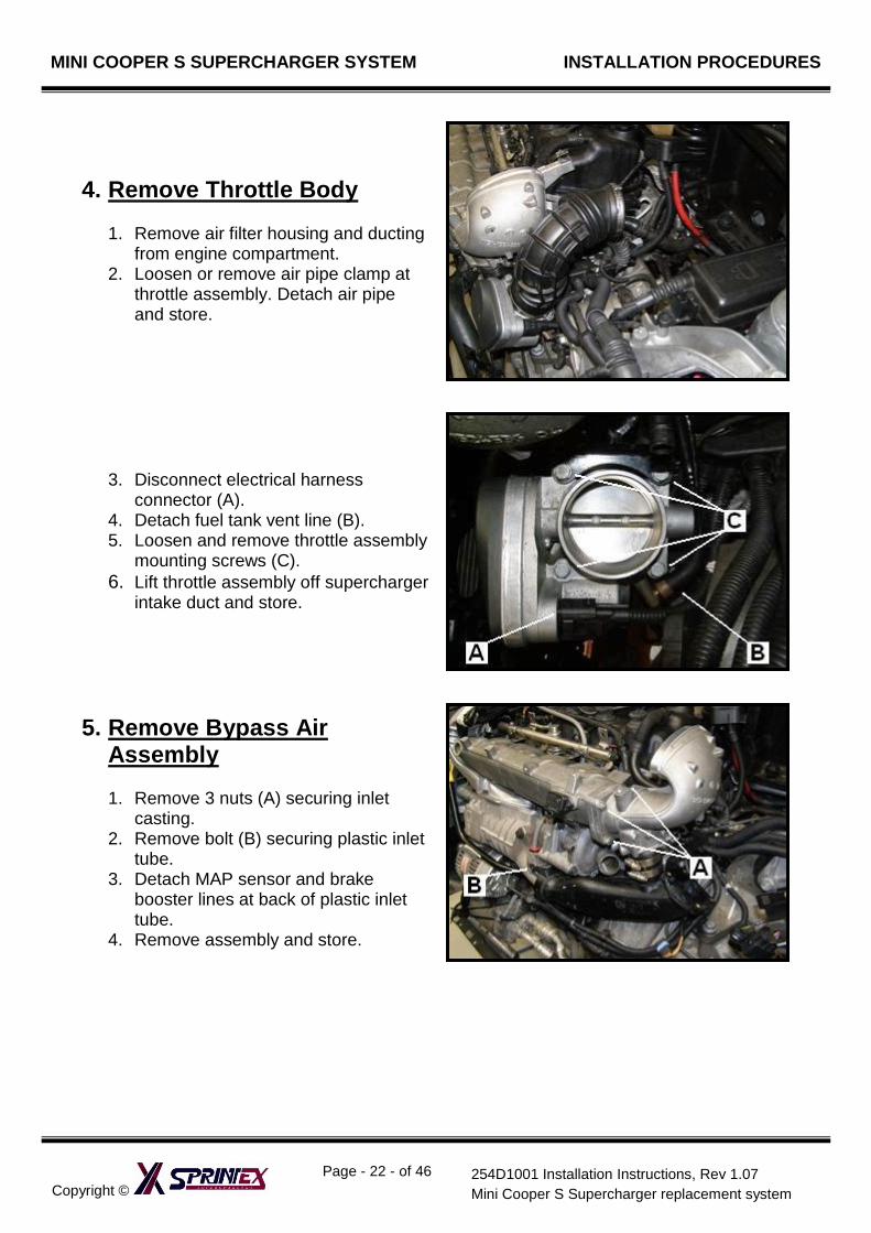
4. Remove Throttle Body
1. Remove air filter housing and ducting from engine compartment.
2. Loosen or remove air pipe clamp at throttle assembly. Detach air pipe and store.
3. Disconnect electrical harness connector (A).
4. Detach fuel tank vent line (B). 5. Loosen and remove throttle assembly
mounting screws (C).
6. Lift throttle assembly off supercharger intake duct and store.
5. Remove Bypass Air Assembly
1. Remove 3 nuts (A) securing inlet
casting. 2. Remove bolt (B) securing plastic inlet
tube. 3. Detach MAP sensor and brake
booster lines at back of plastic inlet tube.
4. Remove assembly and store.
MINI COOPER S SUPERCHARGER SYSTEM INSTALLATION PROCEDURES
Copyright ©
Page - 23 - of 46
254D1001 Installation Instructions, Rev 1.07
Mini Cooper S Supercharger replacement system
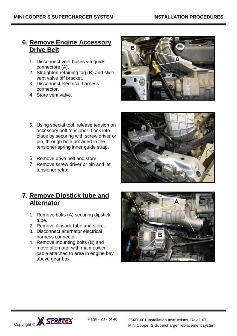
6. Remove Engine Accessory Drive Belt
1. Disconnect vent hoses via quick
connectors (A). 2. Straighten retaining tag (B) and slide
vent valve off bracket. 3. Disconnect electrical harness
connector.
4. Store vent valve.
5. Using special tool, release tension on accessory belt tensioner. Lock into place by securing with screw driver or pin, through hole provided in the tensioner spring inner guide strap.
6. Remove drive belt and store. 7. Remove screw driver or pin and let
tensioner relax.
7. Remove Dipstick tube and Alternator
1. Remove bolts (A) securing dipstick
tube. 2. Remove dipstick tube and store. 3. Disconnect alternator electrical
harness connector. 4. Remove mounting bolts (B) and
move alternator with main power cable attached to area in engine bay above gear box.
MINI COOPER S SUPERCHARGER SYSTEM INSTALLATION PROCEDURES
Copyright ©
Page - 24 - of 46
254D1001 Installation Instructions, Rev 1.07
Mini Cooper S Supercharger replacement system
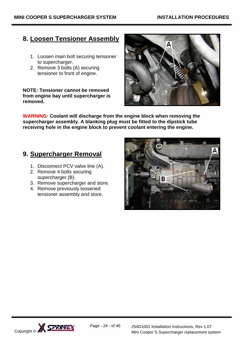
8. Loosen Tensioner Assembly
1. Loosen main bolt securing tensioner to supercharger.
2. Remove 3 bolts (A) securing tensioner to front of engine.
NOTE: Tensioner cannot be removed from engine bay until supercharger is removed.
WARNING: Coolant will discharge from the engine block when removing the supercharger assembly. A blanking plug must be fitted to the dipstick tube receiving hole in the engine block to prevent coolant entering the engine.
9. Supercharger Removal
1. Disconnect PCV valve line (A). 2. Remove 4 bolts securing
supercharger (B). 3. Remove supercharger and store. 4. Remove previously loosened
tensioner assembly and store.
MINI COOPER S SUPERCHARGER SYSTEM INSTALLATION PROCEDURES
Copyright ©
Page - 25 - of 46
254D1001 Installation Instructions, Rev 1.07
Mini Cooper S Supercharger replacement system
MINI COOPER S SUPERCHARGER REPLACEMENT
SYSTEM
SECTION 2
INSTALLATION INSTRUCTIONS
SAFETY WARNING No unauthorised service or alteration may be undertaken to the Sprintex supercharger. Installation should be carried out in a workshop which is a safe and ventilated working environment with equipment and procedures compliant with local authority guidelines and legal requirements. Installers should ensure adequate hearing, eye, and physical protection is used at all times during the installation process. Installers should take reasonable precautions to avoid fatigue and closely follow the installation instructions during every installation. Sprintex recommends installation should not be carried out unsupervised. Sprintex, its directors, employees and agents will not accept liability for damage accident or injury resulting from the installation process. Safety warnings are also provided throughout this document.
MINI COOPER S SUPERCHARGER SYSTEM INSTALLATION PROCEDURES
Copyright ©
Page - 26 - of 46
254D1001 Installation Instructions, Rev 1.07
Mini Cooper S Supercharger replacement system
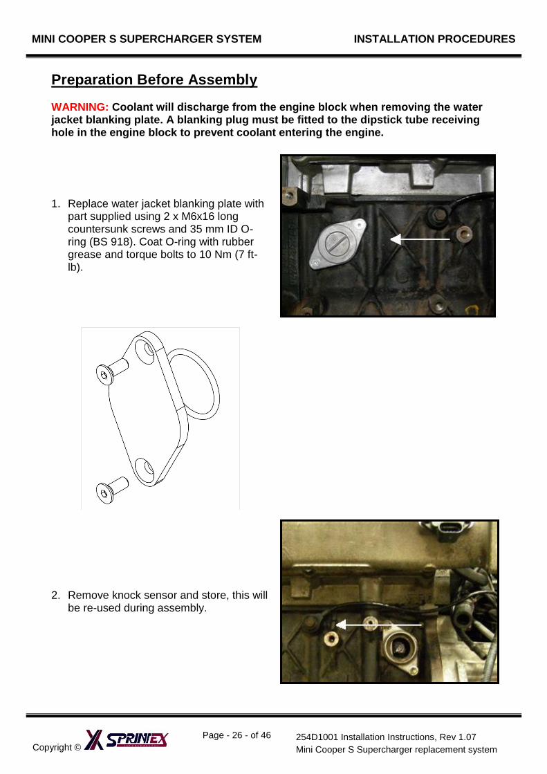
Preparation Before Assembly WARNING: Coolant will discharge from the engine block when removing the water jacket blanking plate. A blanking plug must be fitted to the dipstick tube receiving hole in the engine block to prevent coolant entering the engine.
1. Replace water jacket blanking plate with
part supplied using 2 x M6x16 long countersunk screws and 35 mm ID O-ring (BS 918). Coat O-ring with rubber grease and torque bolts to 10 Nm (7 ft-lb).
2. Remove knock sensor and store, this will be re-used during assembly.
MINI COOPER S SUPERCHARGER SYSTEM INSTALLATION PROCEDURES
Copyright ©
Page - 27 - of 46
254D1001 Installation Instructions, Rev 1.07
Mini Cooper S Supercharger replacement system
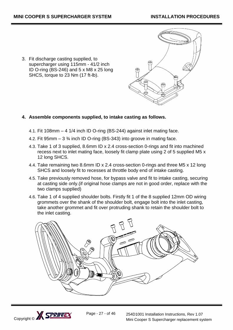
3. Fit discharge casting supplied, to supercharger using 115mm - 41/2 inch ID O-ring (BS-246) and 5 x M8 x 25 long SHCS, torque to 23 Nm (17 ft-lb).
4. Assemble components supplied, to intake casting as follows.
4.1. Fit 108mm – 4 1/4 inch ID O-ring (BS-244) against inlet mating face.
4.2. Fit 95mm – 3 ¾ inch ID O-ring (BS-343) into groove in mating face.
4.3. Take 1 of 3 supplied, 8.6mm ID x 2.4 cross-section 0-rings and fit into machined recess next to inlet mating face, loosely fit clamp plate using 2 of 5 supplied M5 x 12 long SHCS.
4.4. Take remaining two 8.6mm ID x 2.4 cross-section 0-rings and three M5 x 12 long SHCS and loosely fit to recesses at throttle body end of intake casting.
4.5. Take previously removed hose, for bypass valve and fit to intake casting, securing at casting side only.(if original hose clamps are not in good order, replace with the two clamps supplied)
4.6. Take 1 of 4 supplied shoulder bolts. Firstly fit 1 of the 8 supplied 12mm OD wiring grommets over the shank of the shoulder bolt, engage bolt into the inlet casting, take another grommet and fit over protruding shank to retain the shoulder bolt to the inlet casting.
MINI COOPER S SUPERCHARGER SYSTEM INSTALLATION PROCEDURES
Copyright ©
Page - 28 - of 46
254D1001 Installation Instructions, Rev 1.07
Mini Cooper S Supercharger replacement system
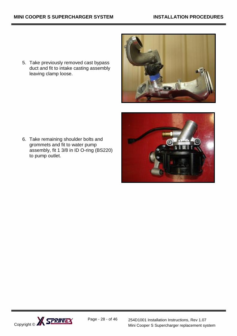
5. Take previously removed cast bypass duct and fit to intake casting assembly leaving clamp loose.
6. Take remaining shoulder bolts and grommets and fit to water pump assembly, fit 1 3/8 in ID O-ring (BS220) to pump outlet.
MINI COOPER S SUPERCHARGER SYSTEM INSTALLATION PROCEDURES
Copyright ©
Page - 29 - of 46
254D1001 Installation Instructions, Rev 1.07
Mini Cooper S Supercharger replacement system
ASSEMBLY
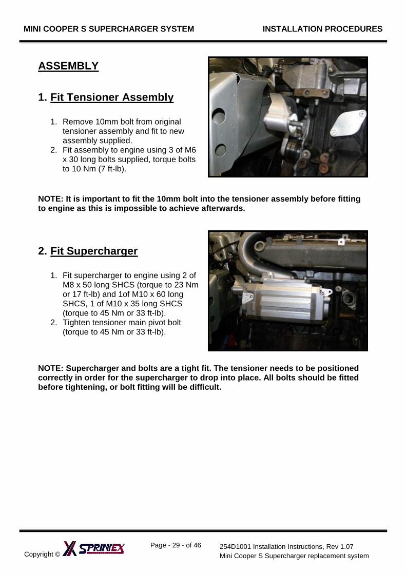
1. Fit Tensioner Assembly
1. Remove 10mm bolt from original tensioner assembly and fit to new assembly supplied.
2. Fit assembly to engine using 3 of M6 x 30 long bolts supplied, torque bolts to 10 Nm (7 ft-lb).
NOTE: It is important to fit the 10mm bolt into the tensioner assembly before fitting to engine as this is impossible to achieve afterwards.
2. Fit Supercharger
1. Fit supercharger to engine using 2 of M8 x 50 long SHCS (torque to 23 Nm or 17 ft-lb) and 1of M10 x 60 long SHCS, 1 of M10 x 35 long SHCS (torque to 45 Nm or 33 ft-lb).
2. Tighten tensioner main pivot bolt (torque to 45 Nm or 33 ft-lb).
NOTE: Supercharger and bolts are a tight fit. The tensioner needs to be positioned correctly in order for the supercharger to drop into place. All bolts should be fitted before tightening, or bolt fitting will be difficult.
MINI COOPER S SUPERCHARGER SYSTEM INSTALLATION PROCEDURES
Copyright ©
Page - 30 - of 46
254D1001 Installation Instructions, Rev 1.07
Mini Cooper S Supercharger replacement system
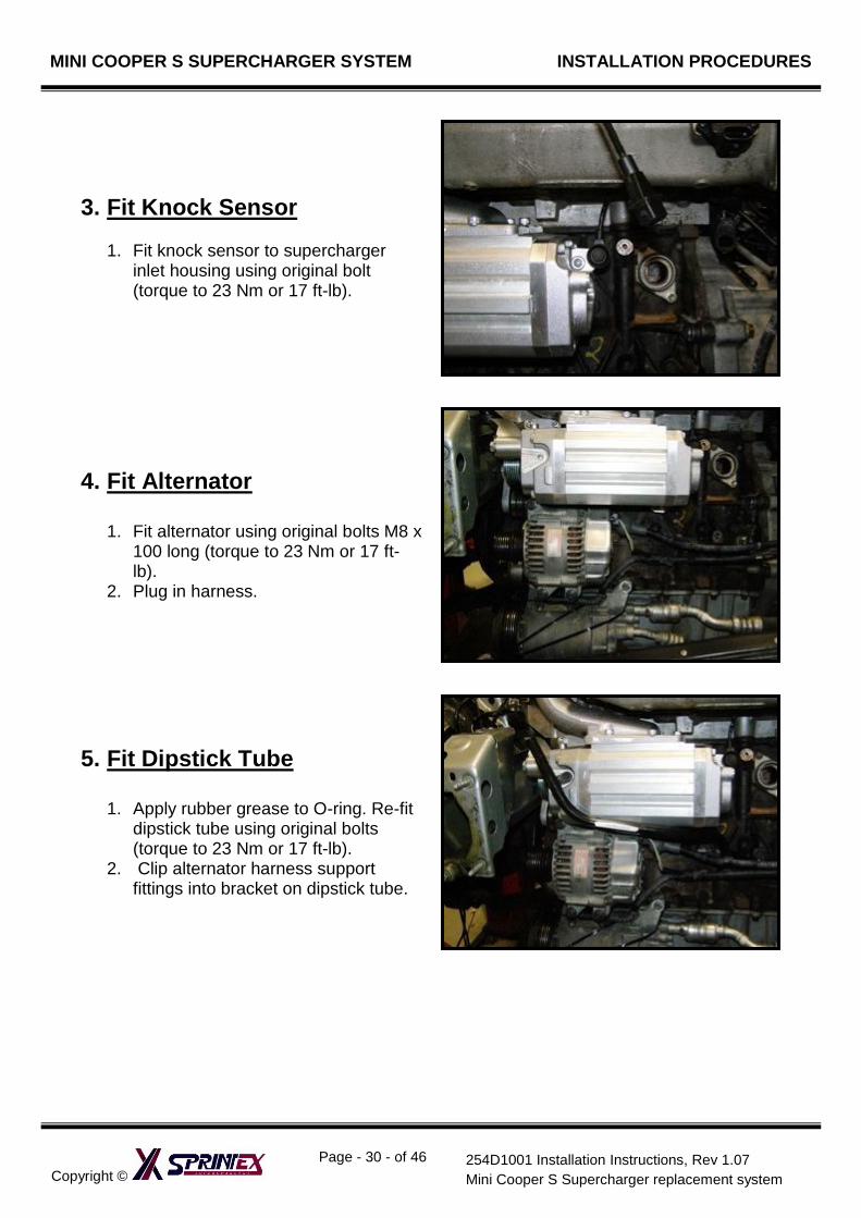
3. Fit Knock Sensor
1. Fit knock sensor to supercharger inlet housing using original bolt (torque to 23 Nm or 17 ft-lb).
4. Fit Alternator
1. Fit alternator using original bolts M8 x 100 long (torque to 23 Nm or 17 ft-lb).
2. Plug in harness.
5. Fit Dipstick Tube
1. Apply rubber grease to O-ring. Re-fit dipstick tube using original bolts (torque to 23 Nm or 17 ft-lb).
2. Clip alternator harness support fittings into bracket on dipstick tube.
MINI COOPER S SUPERCHARGER SYSTEM INSTALLATION PROCEDURES
Copyright ©
Page - 31 - of 46
254D1001 Installation Instructions, Rev 1.07
Mini Cooper S Supercharger replacement system
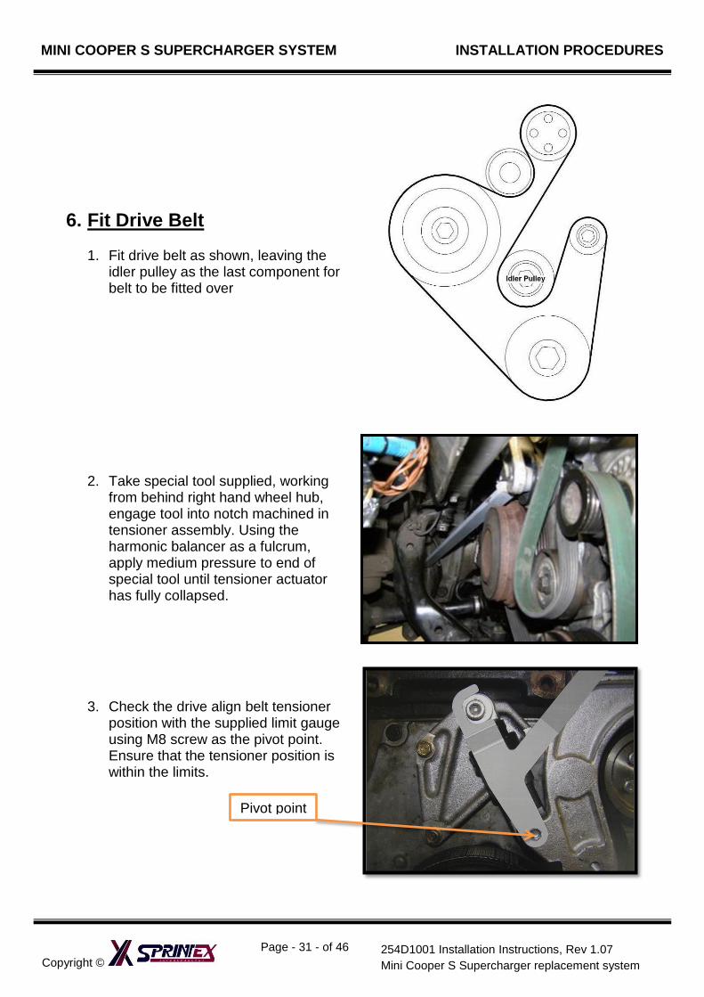
6. Fit Drive Belt
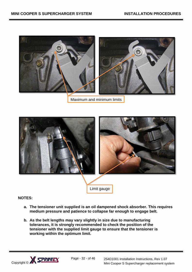
1. Fit drive belt as shown, leaving the idler pulley as the last component for belt to be fitted over
2. Take special tool supplied, working from behind right hand wheel hub, engage tool into notch machined in tensioner assembly. Using the harmonic balancer as a fulcrum, apply medium pressure to end of special tool until tensioner actuator has fully collapsed.
3. Check the drive align belt tensioner position with the supplied limit gauge using M8 screw as the pivot point. Ensure that the tensioner position is within the limits.
Pivot point
MINI COOPER S SUPERCHARGER SYSTEM INSTALLATION PROCEDURES
Copyright ©
Page - 32 - of 46
254D1001 Installation Instructions, Rev 1.07
Mini Cooper S Supercharger replacement system
NOTES:
a. The tensioner unit supplied is an oil dampened shock absorber. This requires medium pressure and patience to collapse far enough to engage belt.
b. As the belt lengths may vary slightly in size due to manufacturing tolerances, it is strongly recommended to check the position of the tensioner with the supplied limit gauge to ensure that the tensioner is working within the optimum limit.
Maximum and minimum limits
Limit gauge
MINI COOPER S SUPERCHARGER SYSTEM INSTALLATION PROCEDURES
Copyright ©
Page - 33 - of 46
254D1001 Installation Instructions, Rev 1.07
Mini Cooper S Supercharger replacement system
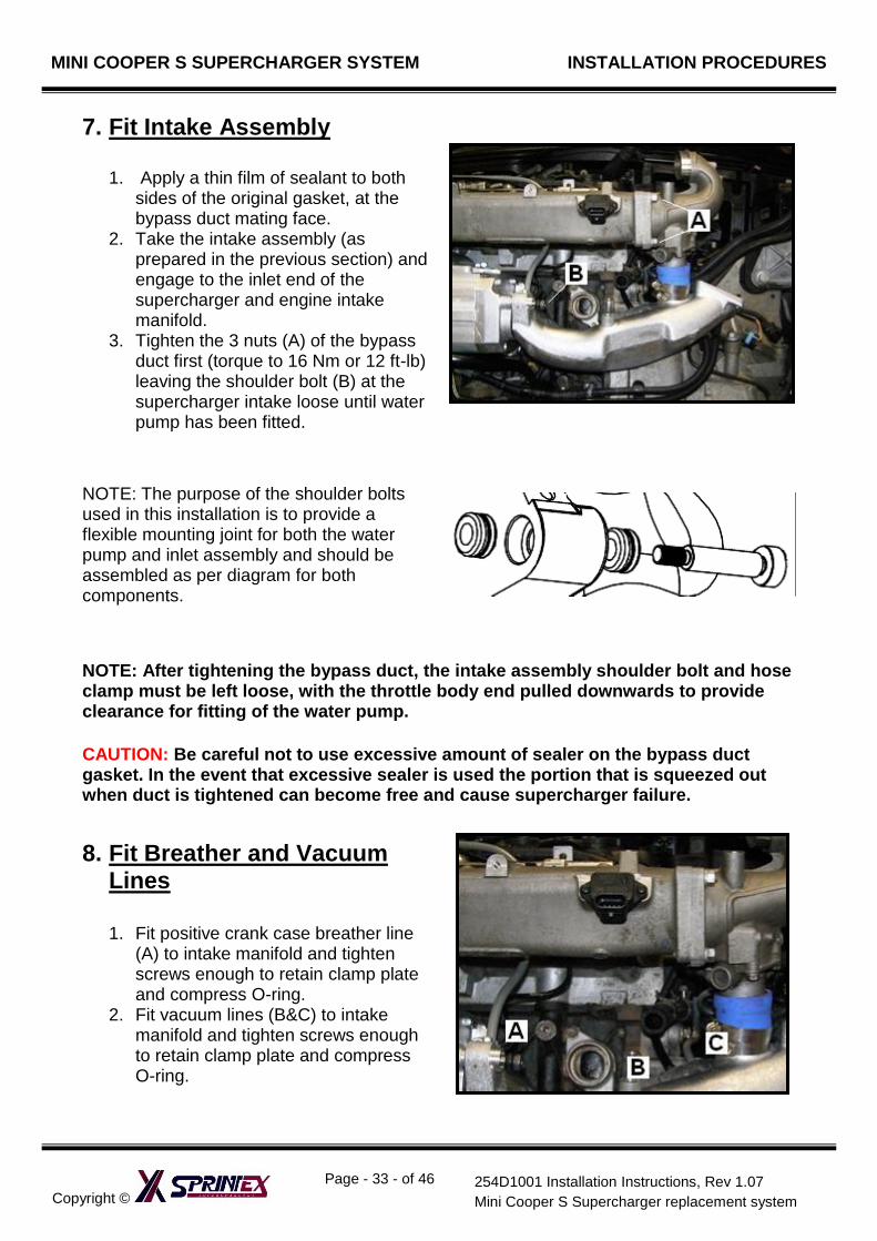
7. Fit Intake Assembly
1. Apply a thin film of sealant to both sides of the original gasket, at the bypass duct mating face.
2. Take the intake assembly (as prepared in the previous section) and engage to the inlet end of the supercharger and engine intake manifold.
3. Tighten the 3 nuts (A) of the bypass duct first (torque to 16 Nm or 12 ft-lb) leaving the shoulder bolt (B) at the supercharger intake loose until water pump has been fitted.
NOTE: The purpose of the shoulder bolts used in this installation is to provide a flexible mounting joint for both the water pump and inlet assembly and should be assembled as per diagram for both components.
NOTE: After tightening the bypass duct, the intake assembly shoulder bolt and hose clamp must be left loose, with the throttle body end pulled downwards to provide clearance for fitting of the water pump.
CAUTION: Be careful not to use excessive amount of sealer on the bypass duct gasket. In the event that excessive sealer is used the portion that is squeezed out when duct is tightened can become free and cause supercharger failure.
8. Fit Breather and Vacuum Lines
1. Fit positive crank case breather line (A) to intake manifold and tighten screws enough to retain clamp plate and compress O-ring.
2. Fit vacuum lines (B&C) to intake manifold and tighten screws enough to retain clamp plate and compress O-ring.
MINI COOPER S SUPERCHARGER SYSTEM INSTALLATION PROCEDURES
Copyright ©
Page - 34 - of 46
254D1001 Installation Instructions, Rev 1.07
Mini Cooper S Supercharger replacement system
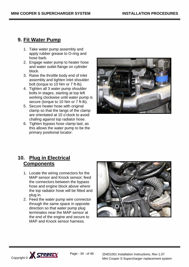
9. Fit Water Pump
1. Take water pump assembly and apply rubber grease to O-ring and hose barb.
2. Engage water pump to heater hose and water outlet flange on cylinder block.
3. Raise the throttle body end of inlet assembly and tighten inlet shoulder bolt (torque to 10 Nm or 7 ft-lb).
4. Tighten all 3 water pump shoulder bolts in stages, starting at top left working clockwise until water pump is secure (torque to 10 Nm or 7 ft-lb).
5. Secure heater hose with original clamp so that the tangs of the clamp are orientated at 10 o’clock to avoid chafing against top radiator hose.
6. Tighten bypass hose clamp last, as this allows the water pump to be the primary positional locator.
10. Plug in Electrical Components
1. Locate the wiring connectors for the
MAP sensor and Knock sensor; feed the connectors between the bypass hose and engine block above where the top radiator hose will be fitted and plug in.
2. Feed the water pump wire connector through the same space in opposite direction so that water pump plug terminates near the MAP sensor at the end of the engine and secure to MAP and Knock sensor harness.
MINI COOPER S SUPERCHARGER SYSTEM INSTALLATION PROCEDURES
Copyright ©
Page - 35 - of 46
254D1001 Installation Instructions, Rev 1.07
Mini Cooper S Supercharger replacement system
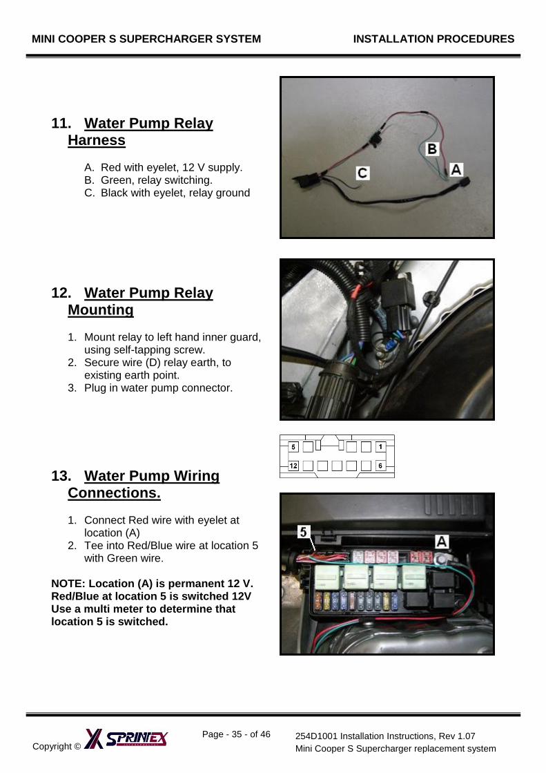
11. Water Pump Relay Harness
A. Red with eyelet, 12 V supply. B. Green, relay switching. C. Black with eyelet, relay ground
12. Water Pump Relay Mounting
1. Mount relay to left hand inner guard,
using self-tapping screw. 2. Secure wire (D) relay earth, to
existing earth point. 3. Plug in water pump connector.
13. Water Pump Wiring Connections.
1. Connect Red wire with eyelet at
location (A) 2. Tee into Red/Blue wire at location 5
with Green wire. NOTE: Location (A) is permanent 12 V. Red/Blue at location 5 is switched 12V Use a multi meter to determine that location 5 is switched.
MINI COOPER S SUPERCHARGER SYSTEM INSTALLATION PROCEDURES
Copyright ©
Page - 36 - of 46
254D1001 Installation Instructions, Rev 1.07
Mini Cooper S Supercharger replacement system
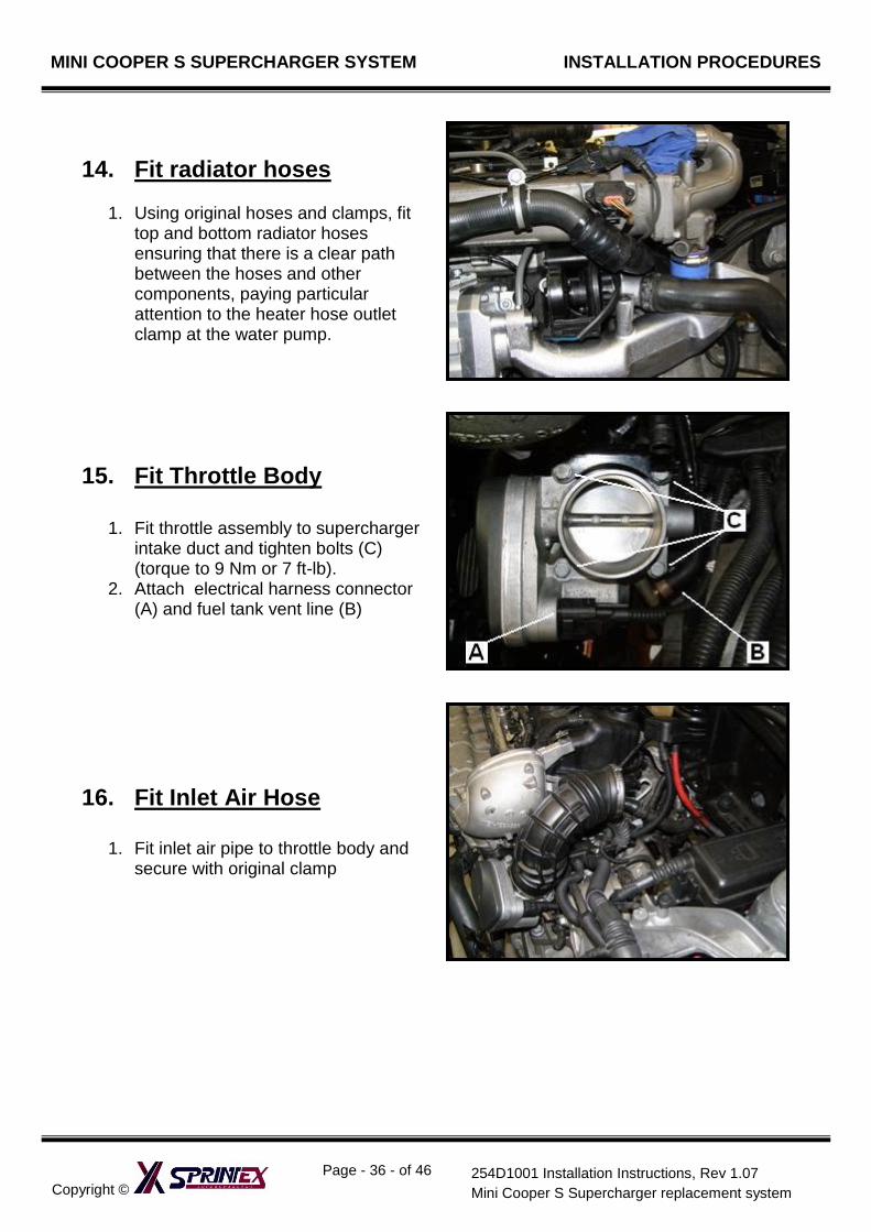
14. Fit radiator hoses
1. Using original hoses and clamps, fit top and bottom radiator hoses ensuring that there is a clear path between the hoses and other components, paying particular attention to the heater hose outlet clamp at the water pump.
15. Fit Throttle Body
1. Fit throttle assembly to supercharger intake duct and tighten bolts (C) (torque to 9 Nm or 7 ft-lb).
2. Attach electrical harness connector (A) and fuel tank vent line (B)
16. Fit Inlet Air Hose
1. Fit inlet air pipe to throttle body and secure with original clamp
MINI COOPER S SUPERCHARGER SYSTEM INSTALLATION PROCEDURES
Copyright ©
Page - 37 - of 46
254D1001 Installation Instructions, Rev 1.07
Mini Cooper S Supercharger replacement system
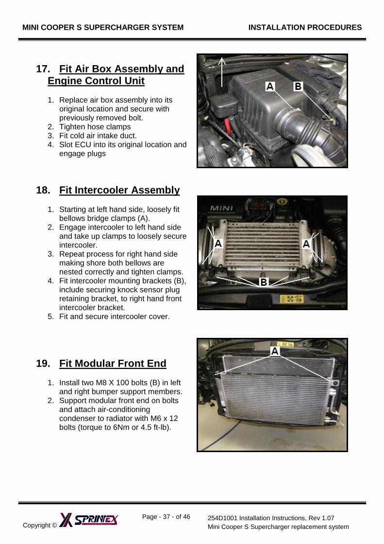
17. Fit Air Box Assembly and Engine Control Unit
1. Replace air box assembly into its
original location and secure with previously removed bolt.
2. Tighten hose clamps 3. Fit cold air intake duct. 4. Slot ECU into its original location and
engage plugs
18. Fit Intercooler Assembly
1. Starting at left hand side, loosely fit bellows bridge clamps (A).
2. Engage intercooler to left hand side and take up clamps to loosely secure intercooler.
3. Repeat process for right hand side making shore both bellows are nested correctly and tighten clamps.
4. Fit intercooler mounting brackets (B), include securing knock sensor plug retaining bracket, to right hand front intercooler bracket.
5. Fit and secure intercooler cover.
19. Fit Modular Front End
1. Install two M8 X 100 bolts (B) in left and right bumper support members.
2. Support modular front end on bolts and attach air-conditioning condenser to radiator with M6 x 12 bolts (torque to 6Nm or 4.5 ft-lb).
MINI COOPER S SUPERCHARGER SYSTEM INSTALLATION PROCEDURES
Copyright ©
Page - 38 - of 46
254D1001 Installation Instructions, Rev 1.07
Mini Cooper S Supercharger replacement system
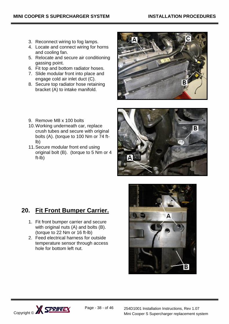
3. Reconnect wiring to fog lamps. 4. Locate and connect wiring for horns
and cooling fan. 5. Relocate and secure air conditioning
gassing point. 6. Fit top and bottom radiator hoses. 7. Slide modular front into place and
engage cold air inlet duct (C). 8. Secure top radiator hose retaining
bracket (A) to intake manifold.
9. Remove M8 x 100 bolts 10. Working underneath car, replace
crush tubes and secure with original bolts (A). (torque to 100 Nm or 74 ft-lb)
11. Secure modular front end using original bolt (B). (torque to 5 Nm or 4 ft-lb)
20. Fit Front Bumper Carrier.
1. Fit front bumper carrier and secure with original nuts (A) and bolts (B). (torque to 22 Nm or 16 ft-lb)
2. Feed electrical harness for outside temperature sensor through access hole for bottom left nut.
MINI COOPER S SUPERCHARGER SYSTEM INSTALLATION PROCEDURES
Copyright ©
Page - 39 - of 46
254D1001 Installation Instructions, Rev 1.07
Mini Cooper S Supercharger replacement system
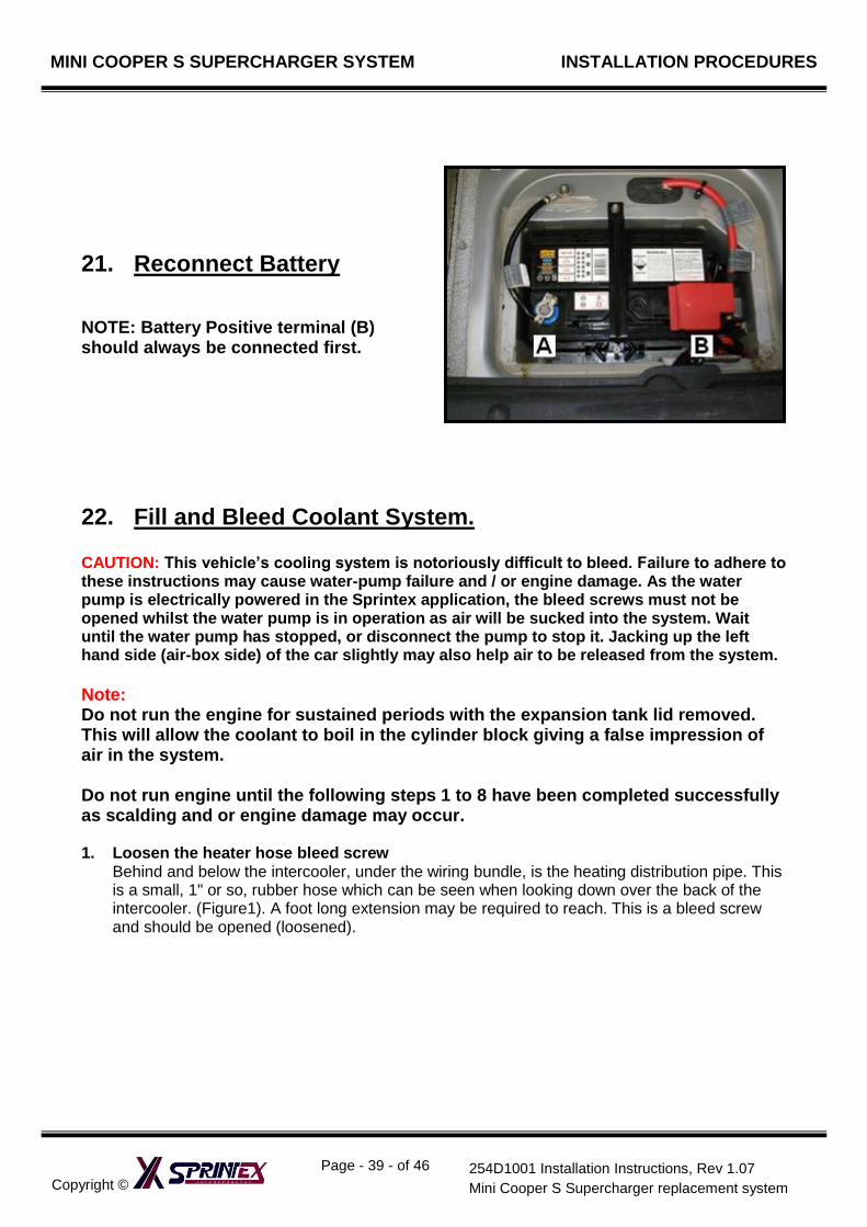
21. Reconnect Battery NOTE: Battery Positive terminal (B) should always be connected first.
22. Fill and Bleed Coolant System. CAUTION: This vehicle’s cooling system is notoriously difficult to bleed. Failure to adhere to these instructions may cause water-pump failure and / or engine damage. As the water pump is electrically powered in the Sprintex application, the bleed screws must not be opened whilst the water pump is in operation as air will be sucked into the system. Wait until the water pump has stopped, or disconnect the pump to stop it. Jacking up the left hand side (air-box side) of the car slightly may also help air to be released from the system.
Note: Do not run the engine for sustained periods with the expansion tank lid removed. This will allow the coolant to boil in the cylinder block giving a false impression of air in the system. Do not run engine until the following steps 1 to 8 have been completed successfully as scalding and or engine damage may occur. 1. Loosen the heater hose bleed screw
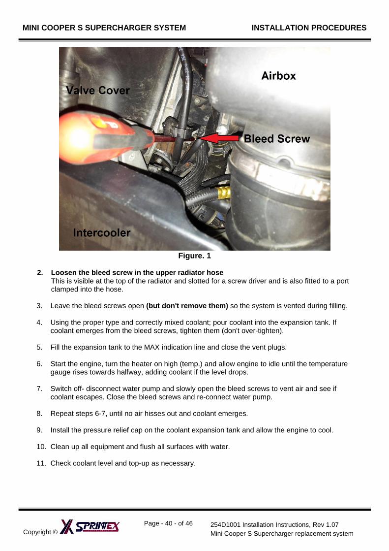
Behind and below the intercooler, under the wiring bundle, is the heating distribution pipe. This is a small, 1" or so, rubber hose which can be seen when looking down over the back of the intercooler. (Figure1). A foot long extension may be required to reach. This is a bleed screw and should be opened (loosened).
MINI COOPER S SUPERCHARGER SYSTEM INSTALLATION PROCEDURES
Copyright ©
Page - 40 - of 46
254D1001 Installation Instructions, Rev 1.07
Mini Cooper S Supercharger replacement system
Figure. 1
2. Loosen the bleed screw in the upper radiator hose
This is visible at the top of the radiator and slotted for a screw driver and is also fitted to a port clamped into the hose.
3. Leave the bleed screws open (but don't remove them) so the system is vented during filling. 4. Using the proper type and correctly mixed coolant; pour coolant into the expansion tank. If
coolant emerges from the bleed screws, tighten them (don't over-tighten). 5. Fill the expansion tank to the MAX indication line and close the vent plugs. 6. Start the engine, turn the heater on high (temp.) and allow engine to idle until the temperature
gauge rises towards halfway, adding coolant if the level drops. 7. Switch off- disconnect water pump and slowly open the bleed screws to vent air and see if
coolant escapes. Close the bleed screws and re-connect water pump. 8. Repeat steps 6-7, until no air hisses out and coolant emerges. 9. Install the pressure relief cap on the coolant expansion tank and allow the engine to cool. 10. Clean up all equipment and flush all surfaces with water. 11. Check coolant level and top-up as necessary.
MINI COOPER S SUPERCHARGER SYSTEM INSTALLATION PROCEDURES
Copyright ©
Page - 41 - of 46
254D1001 Installation Instructions, Rev 1.07
Mini Cooper S Supercharger replacement system
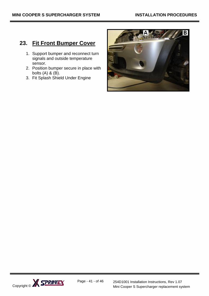
23. Fit Front Bumper Cover
1. Support bumper and reconnect turn signals and outside temperature sensor.
2. Position bumper secure in place with bolts (A) & (B).
3. Fit Splash Shield Under Engine
Copyright ©
Page - 42 - of 46
254D1001 Installation Instructions, Rev 1.07
Mini Cooper S Supercharger replacement system
MINI COOPER S SUPERCHARGER REPLACEMENT SYSTEM
SECTION 3
PRE TEST-DRIVE INSPECTION
SAFETY WARNING
Ensure adequate steps are taken to prevent injury, spillage or fire
should any of the required installation steps
not have been carried out to specification.
MINI COOPER S SUPERCHARGER SYSTEM TESTING PROCEDURES
Copyright ©
Page - 43 - of 46
254D1001 Installation Instructions, Rev 1.07
Mini Cooper S Supercharger replacement system
1. Pre-Start Inspection Ensure coolant is at correct level.
Ensure engine oil is at correct level.
Ensure vehicle has fresh 95 Octane fuel.
Ensure the belt is aligned.
SAFETY WARNING: Ensure adequate steps are taken to prevent injury, spillage or fire.
Engine Warm Up Start engine and allow to run, until engine reaches normal operating temperature.
Check for oil leaks.
Road Test Vehicle Road test vehicle.
Recheck all joints and connections for leaks –rectify as needed.
Copyright ©
Page - 44 - of 46
254D1001 Installation Instructions, Rev 1.07
Mini Cooper S Supercharger replacement system
MINI COOPER S SUPERCHARGER REPLACEMENT SYSTEM
SECTION 4
MAINTENANCE INSTRUCTIONS
MINI COOPER S SUPERCHARGER REPLACEMENT SYSTEM MAINTENANCE PROCEDURES
Copyright ©
Page - 45 - of 46
254D1001 Installation Instructions, Rev 1.07
Mini Cooper S Supercharger replacement system
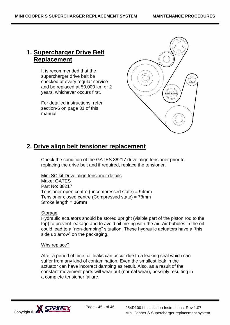
1. Supercharger Drive Belt Replacement
It is recommended that the supercharger drive belt be checked at every regular service and be replaced at 50,000 km or 2 years, whichever occurs first.
For detailed instructions, refer section-6 on page 31 of this manual.
2. Drive align belt tensioner replacement
Check the condition of the GATES 38217 drive align tensioner prior to replacing the drive belt and if required, replace the tensioner.
Mini SC kit Drive align tensioner details Make: GATES Part No: 38217 Tensioner open centre (uncompressed state) = 94mm Tensioner closed centre (Compressed state) = 78mm Stroke length = 16mm
Storage Hydraulic actuators should be stored upright (visible part of the piston rod to the top) to prevent leakage and to avoid oil mixing with the air. Air bubbles in the oil could lead to a “non-damping” situation. These hydraulic actuators have a “this side up arrow” on the packaging.
Why replace?
After a period of time, oil leaks can occur due to a leaking seal which can suffer from any kind of contamination. Even the smallest leak in the actuator can have incorrect damping as result. Also, as a result of the constant movement parts will wear out (normal wear), possibly resulting in a complete tensioner failure.
MINI COOPER S SUPERCHARGER REPLACEMENT SYSTEM MAINTENANCE PROCEDURES
Copyright ©
Page - 46 - of 46
254D1001 Installation Instructions, Rev 1.07
Mini Cooper S Supercharger replacement system
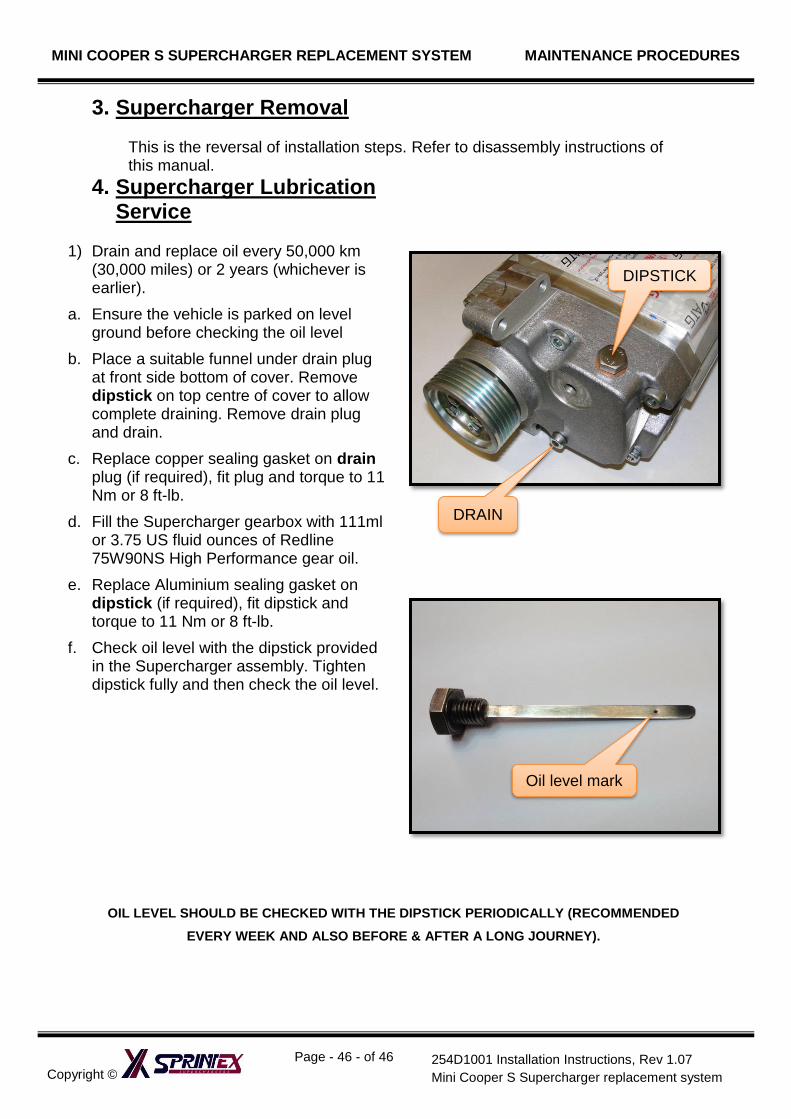
3. Supercharger Removal
This is the reversal of installation steps. Refer to disassembly instructions of this manual.
4. Supercharger Lubrication Service
1) Drain and replace oil every 50,000 km
(30,000 miles) or 2 years (whichever is earlier).
a. Ensure the vehicle is parked on level ground before checking the oil level
b. Place a suitable funnel under drain plug at front side bottom of cover. Remove dipstick on top centre of cover to allow complete draining. Remove drain plug and drain.
c. Replace copper sealing gasket on drain plug (if required), fit plug and torque to 11 Nm or 8 ft-lb.
d. Fill the Supercharger gearbox with 111ml or 3.75 US fluid ounces of Redline 75W90NS High Performance gear oil.
e. Replace Aluminium sealing gasket on dipstick (if required), fit dipstick and torque to 11 Nm or 8 ft-lb.
f. Check oil level with the dipstick provided in the Supercharger assembly. Tighten dipstick fully and then check the oil level.
OIL LEVEL SHOULD BE CHECKED WITH THE DIPSTICK PERIODICALLY (RECOMMENDED
EVERY WEEK AND ALSO BEFORE & AFTER A LONG JOURNEY).
DIPSTICK
DRAIN
Oil level mark