Embed Size (px)
Citation preview

www.usgboral.com
PARTIWALL® INTERTENANCY SOLUTIONS
INSTALLATION MANUALNEW ZEALAND
PB200/3 1 APRIL 2017
Quality ISO 9001
Appraisal No.898 [2015]

2 1 APRIL 2017 | PARTIWALL® INSTALLATION MANUAL NZ
USG BORAL’S PURPOSE … TO CREATE SUSTAINABLE SOLUTIONS FOR A WORLDWIDE BUILDING AND CONSTRUCTION INDUSTRY.
PREFACE USG Boral Building Products is a plasterboard and ceilings manufacturing Joint Venture between USG Corporation and Boral Limited, and is one of the leading players in this field.
Operating throughout Asia, Australasia and in the Middle East, USG Boral Building Products combines USG’s innovative building products technologies with Boral’s extensive plasterboard manufacturing and distribution footprint in Asia and Australia.
Among the successful solutions introduced by the company over the years are: Partiwall® and IntRwall® separating wall systems, OutRwall® and FireClad® fire rated exterior wall systems and many others.
USG Boral Building Products is well positioned to service the Australasian market through its manufacturing facilities in New South Wales, Queensland, Victoria and Auckland.
For more information on USG Boral Building Products refer to www.usgboral.com
INTRODUCTIONThis manual is intended for use by industry professionals and building practitioners. It outlines recommended methods for installation and finishing of USG Boral Partiwall®.
TecASSIST®USG Boral’s Product and Systems Development (PSD) team boasts expertise in lightweight fire rated and acoustic systems, and routinely works with customers to select and, if required, tailor solutions for specific projects.
Together with the TecASSIST® customer help line, USG Boral’s PSD team is well positioned to provide technical support to projects of any size and complexity.
For expert advice on lightweight Building Systems, contact USG Boral TecASSIST® by calling 0800 USGBORAL (0800 874 267).
IS0 9001 QUALITY ASSURANCEUSG Boral Building Products Pty Ltd is a certified ISO 9001 - 2008 manufacturer No. QEC 0400 by SAI Global
STANDARDSThe following Australasian and other Standards are referenced in this publication:
• AS/NZS 2588 Gypsum plasterboard
• AS/NZS 2589 Gypsum linings — Application and finishing
• NZS 3604 Timber framed buildings
• AS/NZS 1170.2 Wind actions
• NZS 1170.5 Earthquake Actions
• AS 1397 Steel sheet and strip — hot dipped, zinc coated or aluminium/zinc coated
• AS 3566 Self-drilling screws for the building and construction industries
• AS/NZS 1716 Respiratory protective devices
• ISO 9001 Quality systems — Model for quality assurance in production, installation and servicing
• AS/NZS 4600 Cold-formed steel structures.
NZBC COMPLIANCEUSG Boral has all the necessary evidence to support that Partiwall® complies with the relevant provisions of the New Zealand Building Code (NZBC) as at 1 April 2017.
Partiwall® complies with NZBC:
• Structure B1
• Durability B2
• Fire Affecting Areas Beyond the Fire Source C3
• Hazardous Building Materials F2
• Airborne/Impact Sound G6
Refer USG Boral Partiwall® System Technical Statement for further compliance details.
BRANZ APPRAISALUSG Boral Partiwall® has been assessed by BRANZ as meeting the relevant NZBC performance clauses.
Quality ISO 9001
Appraisal No.898 [2015]
3PARTIWALL® INSTALLATION MANUAL NZ | 1 APRIL 2017
CONTENTS
Introduction 4
What is Partiwall® ? 4
Features and Benefits 5
How Partiwall® Works 5
Fire 6
Acoustic 6
Structural 7
Isolated Support for Stairs 7
Wet Areas 7
Materials 8
Linings for Occupancy Areas 8
Partiwall® Systems 9
FRR 60/60/60 (System Type PWT60.1) 9
FRR 90/90/90 (System Type PWT90.1) 10
FRR 90/90/90 (System Type PWT90.2) 11
Details 12
Perspective - Section at Roof 12
Typical Floor/Wall Junction 12
Typical Arrangement of Services 12
Concrete Base Details (PW02a) 13
Concrete Base Details (PW02b) 13
Step in Slab Details (PW04a) 13
Step in Slab Details (PW04b) 13
Typical Floor/Wall Junction (PW01) 14
Typical Floor/Wall Junction (PW17) 14
Staggered Floor Detail (PW18) 15
Pitched Roof - Wall/Roof Junction Detail (PW13) 16
Flat Roof - Wall/Roof Junction Detail (PW14) 16
Roof Parapet - Junction Detail (PW15) 17
Box Gutter Detail (PW16) 17
Eave Closure Detail (PW03) 18
Brick Veneer Wall - Junction Detail 1 (PW07) 19
Brick Veneer Wall Junction - Detail 2 (PW08) 20
Clad Wall - Junction Detail (PW09) 20
4-Way Intersecting Wall - Plan Detail (PW11) 21
Typical Corner - Plan Detail (PW10) 21
Internal Wall/Partiwall® Junction (PW22) 22
Wall Penetrations - Plan Details (PW12) 22
uPVC Pipe Penetration at Roof Space (PW19) 23
Power Cables Penetrations at Roof Space (PW20) 23
Copper Pipe Penetration at Roof Space (PW21) 24
Installation of Shaftliner™ Fire Barrier 25
Protection From Weather 25
Do’s and Don’ts 25
Step 1-7 26
Step 8-12 27
Installation Checklist 28
Notes 30
Contacts and Further Information 32
Sustainability 32
Warranty 32
Health and Safety 32
Technical Enquires 32
Sales Enquires 32
4 1 APRIL 2017 | PARTIWALL® INSTALLATION MANUAL NZ
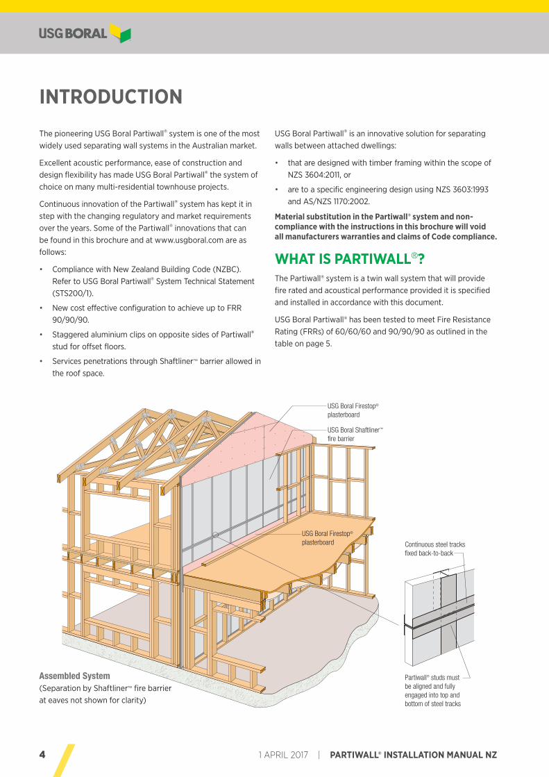
USG Boral Firestop® plasterboard
USG Boral Firestop® plasterboard
USG Boral Shaftliner™ fire barrier
The pioneering USG Boral Partiwall® system is one of the most widely used separating wall systems in the Australian market.
Excellent acoustic performance, ease of construction and design flexibility has made USG Boral Partiwall® the system of choice on many multi-residential townhouse projects.
Continuous innovation of the Partiwall® system has kept it in step with the changing regulatory and market requirements over the years. Some of the Partiwall® innovations that can be found in this brochure and at www.usgboral.com are as follows:
• Compliance with New Zealand Building Code (NZBC). Refer to USG Boral Partiwall® System Technical Statement (STS200/1).
• New cost effective configuration to achieve up to FRR 90/90/90.
• Staggered aluminium clips on opposite sides of Partiwall® stud for offset floors.
• Services penetrations through Shaftliner™ barrier allowed in the roof space.
Assembled System(Separation by Shaftliner™ fire barrier at eaves not shown for clarity)
Continuous steel tracks fixed back-to-back
Partiwall® studs must be aligned and fully engaged into top and bottom of steel tracks
INTRODUCTION
USG Boral Partiwall® is an innovative solution for separating walls between attached dwellings:
• that are designed with timber framing within the scope of NZS 3604:2011, or
• are to a specific engineering design using NZS 3603:1993 and AS/NZS 1170:2002.
Material substitution in the Partiwall® system and non-compliance with the instructions in this brochure will void all manufacturers warranties and claims of Code compliance.
WHAT IS PARTIWALL®?The Partiwall® system is a twin wall system that will provide fire rated and acoustical performance provided it is specified and installed in accordance with this document.
USG Boral Partiwall® has been tested to meet Fire Resistance Rating (FRRs) of 60/60/60 and 90/90/90 as outlined in the table on page 5.
5PARTIWALL® INSTALLATION MANUAL NZ | 1 APRIL 2017
» INTRODUCTION
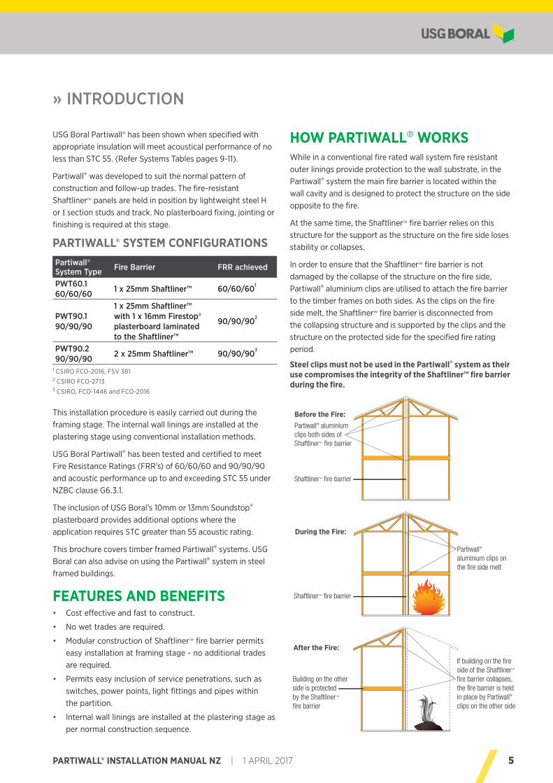
Building on the other side is protectedby the Shaftliner™ fire barrier
If building on the fire side of the Shaftliner™ fire barrier collapses, the fire barrier is held in place by Partiwall® clips on the other side
After the Fire:
Partiwall® aluminium clips on the fire side melt
Shaftliner™ fire barrier
During the Fire:
Shaftliner™ fire barrier
Partiwall® aluminium clips both sides of Shaftliner™ fire barrier
Before the Fire:
USG Boral Partiwall® has been shown when specified with appropriate insulation will meet acoustical performance of no less than STC 55. (Refer Systems Tables pages 9-11).
Partiwall® was developed to suit the normal pattern of construction and follow-up trades. The fire-resistant Shaftliner™ panels are held in position by lightweight steel H or I section studs and track. No plasterboard fixing, jointing or finishing is required at this stage.
This installation procedure is easily carried out during the framing stage. The internal wall linings are installed at the plastering stage using conventional installation methods.
USG Boral Partiwall® has been tested and certified to meet Fire Resistance Ratings (FRR’s) of 60/60/60 and 90/90/90 and acoustic performance up to and exceeding STC 55 under NZBC clause G6.3.1.
The inclusion of USG Boral’s 10mm or 13mm Soundstop® plasterboard provides additional options where the application requires STC greater than 55 acoustic rating.
This brochure covers timber framed Partiwall® systems. USG Boral can also advise on using the Partiwall® system in steel framed buildings.
FEATURES AND BENEFITS • Cost effective and fast to construct.
• No wet trades are required.
• Modular construction of Shaftliner™ fire barrier permits easy installation at framing stage - no additional trades are required.
• Permits easy inclusion of service penetrations, such as switches, power points, light fittings and pipes within the partition.
• Internal wall linings are installed at the plastering stage as per normal construction sequence.
HOW PARTIWALL® WORKSWhile in a conventional fire rated wall system fire resistant outer linings provide protection to the wall substrate, in the Partiwall® system the main fire barrier is located within the wall cavity and is designed to protect the structure on the side opposite to the fire.
At the same time, the Shaftliner™ fire barrier relies on this structure for the support as the structure on the fire side loses stability or collapses.
In order to ensure that the Shaftliner™ fire barrier is not damaged by the collapse of the structure on the fire side, Partiwall® aluminium clips are utilised to attach the fire barrier to the timber frames on both sides. As the clips on the fire side melt, the Shaftliner™ fire barrier is disconnected from the collapsing structure and is supported by the clips and the structure on the protected side for the specified fire rating period.
Steel clips must not be used in the Partiwall® system as their use compromises the integrity of the Shaftliner™ fire barrier during the fire.
PARTIWALL® SYSTEM CONFIGURATIONSPartiwall® System Type Fire Barrier FRR achieved
PWT60.1 60/60/60 1 x 25mm Shaftliner™ 60/60/60
1
PWT90.1 90/90/90
1 x 25mm Shaftliner™ with 1 x 16mm Firestop® plasterboard laminated to the Shaftliner™
90/90/902
PWT90.2 90/90/90 2 x 25mm Shaftliner™ 90/90/90
3
1 CSIRO FCO-2016, FSV 3812 CSIRO FCO-27133 CSIRO, FCO-1446 and FCO-2016
6 1 APRIL 2017 | PARTIWALL® INSTALLATION MANUAL NZ
ACOUSTICThe Partiwall® system has been the subject of a series of acoustic tests at the CSIRO Acoustic Laboratory at Highett, Victoria.
Acoustical estimates have been determined by Renzo Tonin and Associates Pty Ltd a member firm of the Association of Australian Acoustical Consultants (AAAC).
Selection of internal lining and insulation material will determine ultimate acoustical performance of the Partiwall® system. Refer to this manual when specifying these elements of the system.
Small penetrations of linings in occupancy areas ie switches, power points, light fittings and pipes need to be acoustically sealed. (ref page 12, lower diagram)
Shaftliner™ fire barrier base and internal lining junctions with floors must be sealed with Firesound™ sealant.
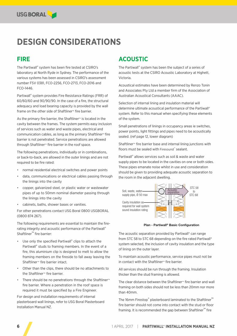
Partiwall® allows services such as soil & waste and water supply pipes to be located in the cavities on one or both sides. These pipes emanate noise whilst in use and consideration should be given to providing adequate acoustic separation to the room in the adjacent dwelling.
The acoustic separation provided by Partiwall® can range from STC 58 to STC 68 depending on the fire rated Partiwall® system selected, the inclusion of cavity insulation and the type of lining on the outer layer.
To maintain acoustic performance, service pipes must not be in contact with the Shaftliner™ fire barrier.
All services should be run through the framing. Insulation thicker than the stud framing is allowed.
The clear distance between the Shaftliner™ fire barrier and wall framing on both sides should not be less than 20mm nor more than 40mm.
The 16mm Firestop® plasterboard laminated to the Shaftliner™ fire barrier should not come into contact with the stud or floor framing. It is recommended the gap between Shaftliner™ fire
DESIGN CONSIDERATIONS
FIREThe Partiwall® system has been fire tested at CSIRO’s laboratory at North Ryde in Sydney. The performance of the various systems has been assessed in CSIRO’s assessment number FSV 0381, FCO-2256, FCO-2713, FCO-2016 and FCO-1446.
Partiwall® system provides Fire Resistance Ratings (FRR) of 60/60/60 and 90/90/90. In the case of a fire, the structural adequacy and load bearing capacity is provided by the wall frame on the other side of Shaftliner™ fire barrier.
As the primary fire barrier, the Shaftliner™ is located in the cavity between the frames. The system permits easy inclusion of services such as water and waste pipes, electrical and communication cables, as long as the primary Shaftliner™ fire barrier is not penetrated. Service penetrations are allowed through Shaftliner™ fire barrier in the roof space.
The following penetrations, individually or in combinations, or back-to-back, are allowed in the outer linings and are not required to be fire rated:
• normal residential electrical switches and power points
• data, communications or electrical cables passing through the linings into the cavity
• copper, galvanized steel, or plastic water or wastewater pipes of up to 50mm nominal diameter passing through the linings into the cavity
• cabinets, baths, shower bases or vanities.
For other penetrations contact USG Boral 0800 USGBORAL (0800 874 267).
The following requirements are essential to maintain the fire-rating integrity and acoustic performance of the Partiwall® Shaftliner™ fire barrier:
• Use only the specified Partiwall® clips to attach the Partiwall® studs to framing members. In the event of a fire, this aluminium clip is designed to melt to allow the framing members on the fireside to fall away leaving the Shaftliner™ fire barrier intact.
• Other than the clips, there should be no attachments to the Shaftliner™ fire barrier.
• There should be no penetrations through the Shaftliner™ fire barrier. Where a penetration in the roof space is required it must be specified by a Fire Engineer.
For design and installation requirements of internal plasterboard wall linings, refer to USG Boral Plasterboard Installation Manual NZ.
Cavity insulation as required for wall system sound insulation rating
Soil, waste, water supply pipe, Ø 50 max
STC 58 to
STC 68
Acousticseparation
Plan - Partiwall® Basic Configuration
7PARTIWALL® INSTALLATION MANUAL NZ | 1 APRIL 2017
WIND SPEED AND SEISMICThe Partiwall® system is suitable for use in all NZS 3604 Wind and Earthquake Zones. The Partiwall® system may also be specifically engineered for other designs using AS/NZS 1170.
POST FIRE STRENGTHThe exposed Shaftliner™ will resist a 0.5kPa wind load after a fire, in accordance with NZBC Verification Method B1/VM1 Section 2.2.4.
SUPPORT CLIP SEPARATIONClips each side of the Shaftliner™ fire barrier H-stud must be spaced at no more than 2700mm vertically and 600mm horizontally unless noted otherwise. For clips spaced between 2700mm and 3000mm please contact USG Boral for installation details.
FRAMINGTimber framing to be designed in accordance with NZS 3604 or specifically engineered in accordance with AS/NZS 1170 by a suitably qualified Structural Engineer to meet NZBC requirements and relevant New Zealand Standards.
Note: Stud spacing not to exceed 600mm centres.
BRACINGIf the Partiwall® is required to provide structural bracing values, please contact USG Boral.
WET AREASIn wet areas USG Boral recommends the use of moisture resistant internal lining plasterboards such as Multistop 4 and Fiberock® Aqua-Tough™ in order to achieve required fire and acoustic ratings:
For installation details of USG Boral Wet Area Systems refer USG Boral Plasterboard Installation Manual NZ.
LININGS FOR OCCUPANCY AREASLinings in the occupancy areas (including Wet Area specified in some Partiwall® Wet Area Systems) do not need be fire rated and are constructed using the normal installation and finishing methods outlined in the USG Boral Plasterboard Installation Manual NZ. Base of linings must be acoustically sealed with specified Firesound™ sealant.
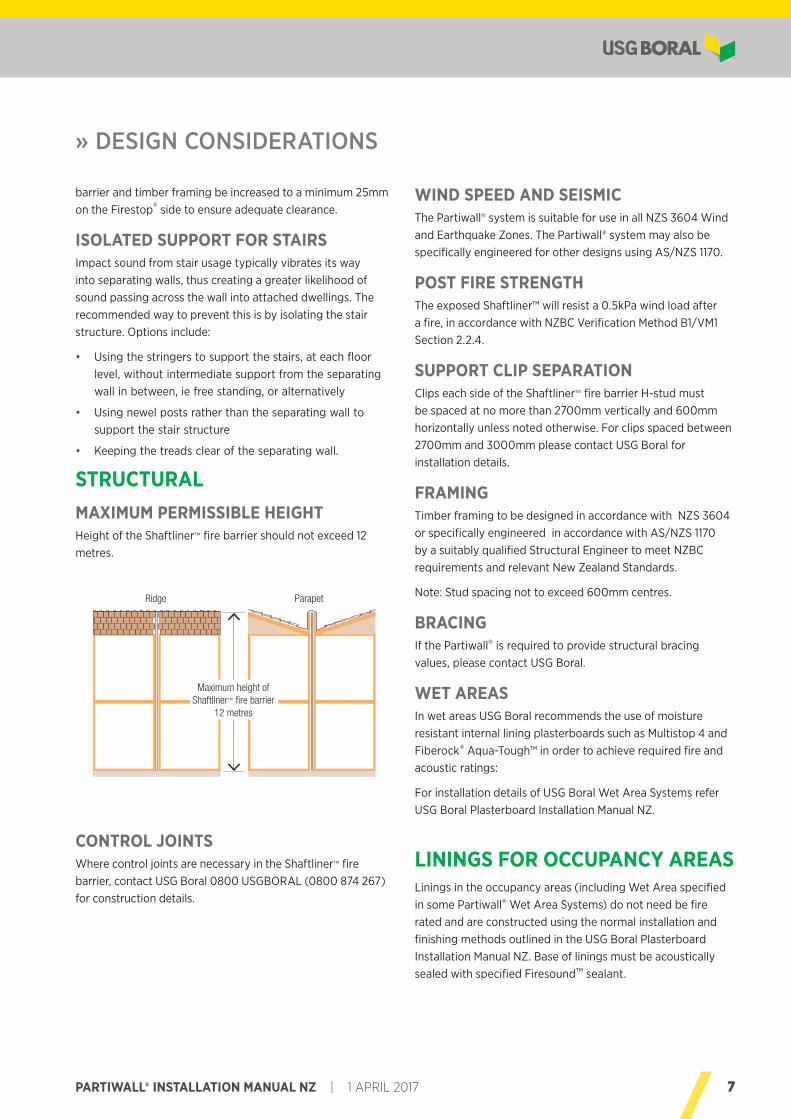
Ridge Parapet
Maximum height of Shaftliner™ fire barrier
12 metres
barrier and timber framing be increased to a minimum 25mm on the Firestop® side to ensure adequate clearance.
ISOLATED SUPPORT FOR STAIRSImpact sound from stair usage typically vibrates its way into separating walls, thus creating a greater likelihood of sound passing across the wall into attached dwellings. The recommended way to prevent this is by isolating the stair structure. Options include:
• Using the stringers to support the stairs, at each floor level, without intermediate support from the separating wall in between, ie free standing, or alternatively
• Using newel posts rather than the separating wall to support the stair structure
• Keeping the treads clear of the separating wall.
STRUCTURALMAXIMUM PERMISSIBLE HEIGHTHeight of the Shaftliner™ fire barrier should not exceed 12 metres.
CONTROL JOINTSWhere control joints are necessary in the Shaftliner™ fire barrier, contact USG Boral 0800 USGBORAL (0800 874 267) for construction details.
» DESIGN CONSIDERATIONS

8 1 APRIL 2017 | PARTIWALL® INSTALLATION MANUAL NZ
HB FullerFiresound™ sealant, 450g tube
FBSOUND450
Firesound™ sealant, 600ml sausage FBSOUND900
6g x 25mm Type ‘W’ Timber Screws S625WB
6g x 32mm Type ‘W’ Timber Screws (for bracing systems)
S632WB
10g x 40mm Type ‘L’ Laminating Screws Pkt 1000
S1040LB
10g x 16mm Type ‘D’ Drill Point Wafer Head Screws
S1016DBB
10g x 30mm Type ‘D’ Drill Point Wafer Head Screws
S1030DB
30mm Galvanized Nails NC3028PO
USG Boral Firepack™
Mineral wool packer 5m x 200 x 50mm, Pkt 3
IIPWBATT
MATERIALS
All materials are available from USG Boral and must be installed in accordance with current instructions found on the USG Boral website (www.usgboral.com). All materials should be stored clear of the ground and provided protection from damage and exposure to the elements.
The following materials are required for the installation of the Shaftliner™ fire barrier:
USG Boral Partiwall® Components
Product Image Item Description Item Codes
25mm Shaftliner™ 600 x 3000mm 25SW0630
25mm Shaftliner™ 600 x 3600mm 25SW0636
16mm Firestop® 1200 x 2400mm 16FS1224
Partiwall® stud 25mm H-Stud x 3000mm R25HS3055
25mm H-Stud x 3600mm R25HS3655
51mm I-Stud x 3000mm RO51IS300055
51mm I-Stud x 3600mm RO51IS360055
Partiwall® track25mm Track x 3000mmx 3600mm
PT2530PT2536
51mm Wall Track x 3000mm
WT51
Partiwall® clip
Aluminium wall clip RPWALLCLIP
USG Boral Partiwall® Components
Product Image Item Description Item Codes
Call USG Boral for information on the range of insulation listed in the Partiwall® Systems tables
Note:Partiwall® performance values stated in this document are based on the use of materials and components listed above. Material substitution may effect the performance of Partiwall® systems. Please contact TecASSIST on 0800 USGBORAL (0800 874 267) for advice.
9PARTIWALL® INSTALLATION MANUAL NZ | 1 APRIL 2017
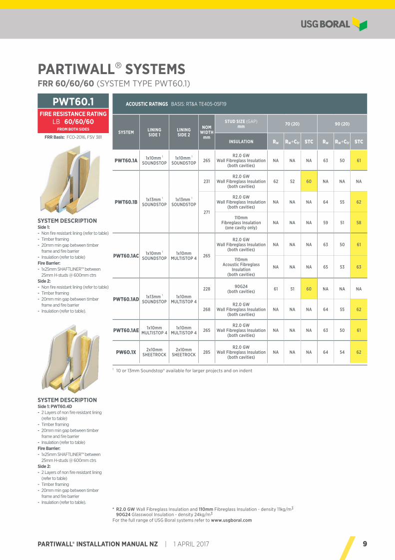
PARTIWALL® SYSTEMSFRR 60/60/60 (SYSTEM TYPE PWT60.1)
ACOUSTIC RATINGS BASIS: RT&A TE405-05F19
SYSTEM LINING SIDE 1
LINING SIDE 2
NOM WIDTH
mm
STUD SIZE (GAP) mm 70 (20) 90 (20)
INSULATION Rw Rw+Ctr STC Rw Rw+Ctr STC
PWT60.1A 1x10mm 1 SOUNDSTOP
1x10mm 1
SOUNDSTOP 265R2.0 GW
Wall Fibreglass Insulation (both cavities)
NA NA NA 63 50 61
PWT60.1B 1x13mm 1
SOUNDSTOP1x13mm 1
SOUNDSTOP
231R2.0 GW
Wall Fibreglass Insulation (both cavities)
62 52 60 NA NA NA
271
R2.0 GW Wall Fibreglass Insulation
(both cavities)NA NA NA 64 55 62
110mm Fibreglass Insulation
(one cavity only)NA NA NA 59 51 58
PWT60.1AC 1x10mm 1
SOUNDSTOP1x10mm
MULTISTOP 4 265
R2.0 GW Wall Fibreglass Insulation
(both cavities)NA NA NA 63 50 61
110mm Acoustic Fibreglass
Insulation (both cavities)
NA NA NA 65 53 63
PWT60.1AD 1x13mm 1
SOUNDSTOP1x10mm
MULTISTOP 4
228 90G24 (both cavities) 61 51 60 NA NA NA
268R2.0 GW
Wall Fibreglass Insulation (both cavities)
NA NA NA 64 55 62
PWT60.1AE 1x10mm MULTISTOP 4
1x10mm MULTISTOP 4 265
R2.0 GW Wall Fibreglass Insulation
(both cavities)NA NA NA 63 50 61
PW6O.1X 2x10mm SHEETROCK
2x10mm SHEETROCK 285
R2.0 GW Wall Fibreglass Insulation
(both cavities)NA NA NA 64 54 62
PWT60.1FIRE RESISTANCE RATING
LB 60/60/60FROM BOTH SIDES
For the full range of USG Boral systems refer to www.usgboral.com
FRR Basis: FCO-2016, FSV 381
SYSTEM DESCRIPTIONSide 1: PWT60.4D - 2 Layers of non fire resistant lining (refer to table)
- Timber framing - 20mm min gap between timber frame and fire barrier
- Insulation (refer to table)Fire Barrier: - 1x25mm SHAFTLINER™ between 25mm H-studs @ 600mm ctrs
Side 2: - 2 Layers of non fire resistant lining (refer to table)
- Timber framing - 20mm min gap between timber frame and fire barrier
- Insulation (refer to table).
SYSTEM DESCRIPTIONSide 1: - Non fire resistant lining (refer to table) - Timber framing - 20mm min gap between timber frame and fire barrier
- Insulation (refer to table)Fire Barrier: - 1x25mm SHAFTLINER™ between 25mm H-studs @ 600mm ctrs
Side 2: - Non fire resistant lining (refer to table) - Timber framing - 20mm min gap between timber frame and fire barrier
- Insulation (refer to table).
* R2.0 GW Wall Fibreglass Insulation and 110mm Fibreglass Insulation - density 11kg/m3 90G24 Glasswool Insulation - density 24kg/m3
1 10 or 13mm Soundstop® available for larger projects and on indent
10 1 APRIL 2017 | PARTIWALL® INSTALLATION MANUAL NZ
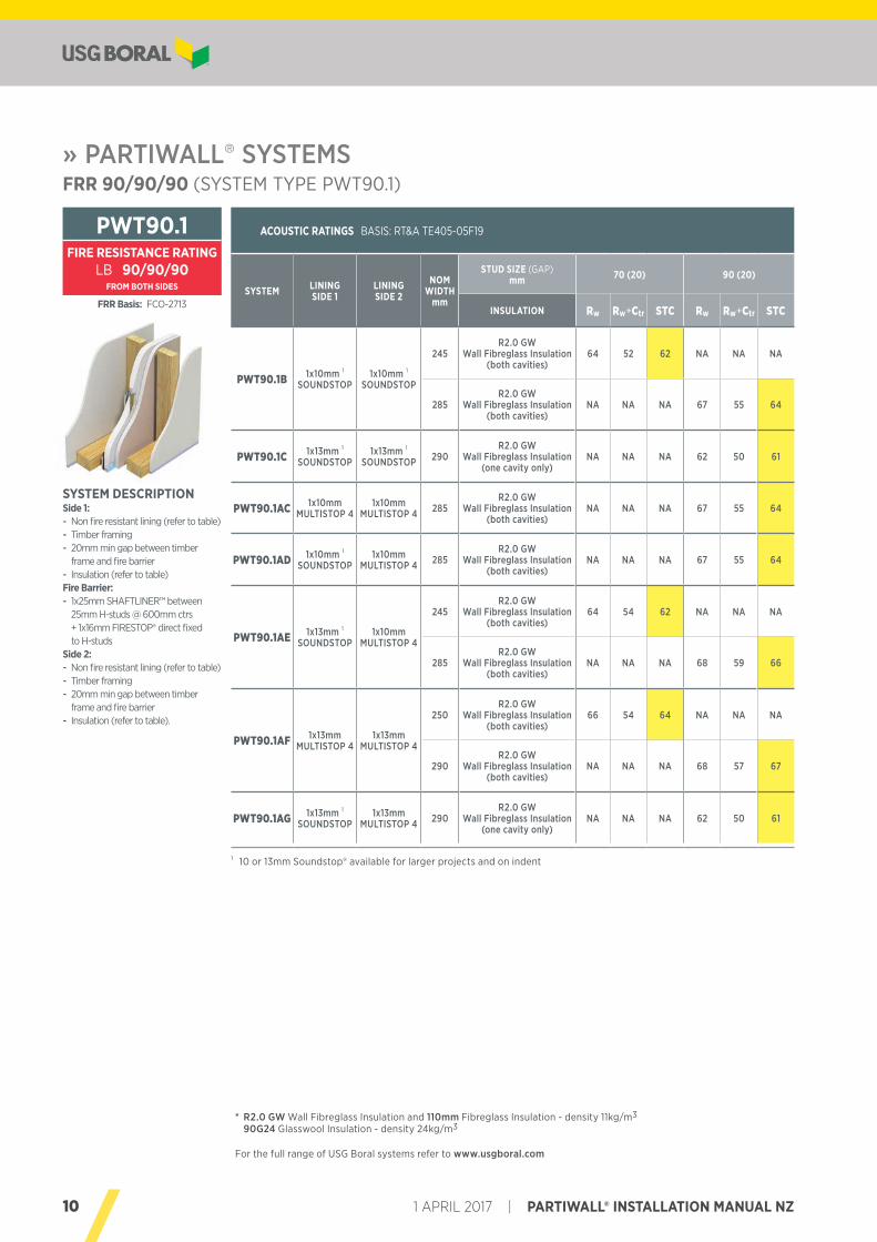
» PARTIWALL® SYSTEMSFRR 90/90/90 (SYSTEM TYPE PWT90.1)
ACOUSTIC RATINGS BASIS: RT&A TE405-05F19
SYSTEM LINING SIDE 1
LINING SIDE 2
NOM WIDTH
mm
STUD SIZE (GAP) mm 70 (20) 90 (20)
INSULATION Rw Rw+Ctr STC Rw Rw+Ctr STC
PWT90.1B 1x10mm 1
SOUNDSTOP1x10mm 1
SOUNDSTOP
245R2.0 GW
Wall Fibreglass Insulation (both cavities)
64 52 62 NA NA NA
285R2.0 GW
Wall Fibreglass Insulation (both cavities)
NA NA NA 67 55 64
PWT90.1C 1x13mm 1
SOUNDSTOP1x13mm 1
SOUNDSTOP 290R2.0 GW
Wall Fibreglass Insulation (one cavity only)
NA NA NA 62 50 61
PWT90.1AC 1x10mm MULTISTOP 4
1x10mm MULTISTOP 4 285
R2.0 GW Wall Fibreglass Insulation
(both cavities)NA NA NA 67 55 64
PWT90.1AD 1x10mm 1
SOUNDSTOP1x10mm
MULTISTOP 4 285R2.0 GW
Wall Fibreglass Insulation (both cavities)
NA NA NA 67 55 64
PWT90.1AE 1x13mm 1
SOUNDSTOP1x10mm
MULTISTOP 4
245R2.0 GW
Wall Fibreglass Insulation (both cavities)
64 54 62 NA NA NA
285R2.0 GW
Wall Fibreglass Insulation (both cavities)
NA NA NA 68 59 66
PWT90.1AF 1x13mm MULTISTOP 4
1x13mm MULTISTOP 4
250R2.0 GW
Wall Fibreglass Insulation (both cavities)
66 54 64 NA NA NA
290R2.0 GW
Wall Fibreglass Insulation (both cavities)
NA NA NA 68 57 67
PWT90.1AG 1x13mm 1
SOUNDSTOP1x13mm
MULTISTOP 4 290R2.0 GW
Wall Fibreglass Insulation (one cavity only)
NA NA NA 62 50 61
SYSTEM DESCRIPTIONSide 1: - Non fire resistant lining (refer to table) - Timber framing - 20mm min gap between timber frame and fire barrier
- Insulation (refer to table)Fire Barrier: - 1x25mm SHAFTLINER™ between 25mm H-studs @ 600mm ctrs + 1x16mm FIRESTOP® direct fixed to H-studs
Side 2: - Non fire resistant lining (refer to table) - Timber framing - 20mm min gap between timber frame and fire barrier
- Insulation (refer to table).
PWT90.1FIRE RESISTANCE RATING
LB 90/90/90FROM BOTH SIDES
FRR Basis: FCO-2713
* R2.0 GW Wall Fibreglass Insulation and 110mm Fibreglass Insulation - density 11kg/m3 90G24 Glasswool Insulation - density 24kg/m3
For the full range of USG Boral systems refer to www.usgboral.com
1 10 or 13mm Soundstop® available for larger projects and on indent
11PARTIWALL® INSTALLATION MANUAL NZ | 1 APRIL 2017
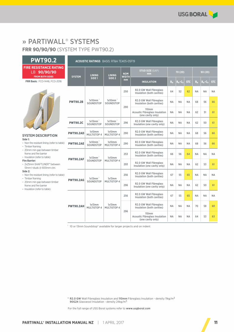
» PARTIWALL® SYSTEMSFRR 90/90/90 (SYSTEM TYPE PWT90.2)
ACOUSTIC RATINGS BASIS: RT&A TE405-05F19
SYSTEM LINING SIDE 1
LINING SIDE 2
NOM WIDTH
mm
STUD SIZE (GAP) mm 70 (20) 90 (20)
INSULATION Rw Rw+Ctr STC Rw Rw+Ctr STC
PWT90.2B 1x10mm 1
SOUNDSTOP1x10mm 1
SOUNDSTOP
250 R2.0 GW Wall Fibreglass Insulation (both cavities) 64 52 62 NA NA NA
290
R2.0 GW Wall Fibreglass Insulation (both cavities) NA NA NA 68 56 66
110mm Acoustic Fibreglass Insulation
(one cavity only)NA NA NA 62 51 61
PWT90.2C 1x13mm 1
SOUNDSTOP1x13mm 1
SOUNDSTOP 296 R2.0 GW Wall Fibreglass Insulation (one cavity only) NA NA NA 62 50 61
PWT90.2AD 1x10mm MULTISTOP 4
1x10mm MULTISTOP 4 290 R2.0 GW Wall Fibreglass
Insulation (both cavities) NA NA NA 68 56 66
PWT90.2AE 1x10mm 1
SOUNDSTOP1x10mm
MULTISTOP 4 290 R2.0 GW Wall Fibreglass Insulation (both cavities) NA NA NA 68 56 66
PWT90.2AF 1x13mm 1
SOUNDSTOP1x10mm
MULTISTOP 4
253 R2.0 GW Wall Fibreglass Insulation (both cavities) 66 56 64 NA NA NA
293 R2.0 GW Wall Fibreglass Insulation (one cavity only) NA NA NA 62 53 61
PWT90.2AG 1x13mm 1
SOUNDSTOP1x13mm
MULTISTOP 4
256 R2.0 GW Wall Fibreglass Insulation (both cavities) 67 55 65 NA NA NA
296 R2.0 GW Wall Fibreglass Insulation (one cavity only) NA NA NA 62 50 61
PWT90.2AH 1x13mm MULTISTOP 4
1x13mm MULTISTOP 4
256 R2.0 GW Wall Fibreglass Insulation (both cavities) 67 55 65 NA NA NA
296
R2.0 GW Wall Fibreglass Insulation (both cavities) NA NA NA 70 58 68
110mm Acoustic Fibreglass Insulation
(one cavity only)NA NA NA 64 53 63
SYSTEM DESCRIPTIONSide 1: - Non fire resistant lining (refer to table) - Timber framing - 20mm min gap between timber frame and fire barrier
- Insulation (refer to table)Fire Barrier: - 2x25mm SHAFTLINER™ between 51mm I-studs @ 600mm ctrs
Side 2: - Non fire resistant lining (refer to table) - Timber framing - 20mm min gap between timber frame and fire barrier
- Insulation (refer to table).
PWT90.2FIRE RESISTANCE RATING
LB 90/90/90FROM BOTH SIDES
FRR Basis: FCO-1446, FCO-2016
* R2.0 GW Wall Fibreglass Insulation and 110mm Fibreglass Insulation - density 11kg/m3 90G24 Glasswool Insulation - density 24kg/m3
For the full range of USG Boral systems refer to www.usgboral.com
1 10 or 13mm Soundstop® available for larger projects and on indent
12 1 APRIL 2017 | PARTIWALL® INSTALLATION MANUAL NZ
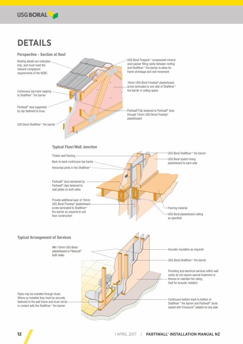
Perspective - Section at Roof
Typical Floor/Wall Junction
DETAILS
Roofing details are indicative only, and must meet the relevant compliance requirements of the NZBC
Continuous top track capping to Shaftliner™ fire barrier
Partiwall® stud supported by clip fastened to truss
USG Boral Shaftliner™ fire barrier
USG Boral Firepack™ compressed mineral wool packer filling cavity between roofing and Shaftliner™ fire barrier to allow for frame shrinkage and roof movement
16mm USG Boral Firestop® plasterboard, screw laminated to one side of Shaftliner™ fire barrier in ceiling space
Partiwall®Clip fastened to Partiwall® stud through 16mm USG Boral Firestop® plasterboard
Timber wall framing
Back-to-back continuous top tracks
Horizontal joints in the Shaftliner™
Partiwall® stud restrained by Partiwall® clips fastened to wall plates on both sides
Provide additional layer of 16mm USG Boral Firestop® plasterboard screw laminated to Shaftliner™ fire barrier as required to suit floor construction
USG Boral Shaftliner™ fire barrier
USG Boral system lining plasterboard to each side
Flooring material
USG Boral plasterboard ceiling as specified
Min 10mm USG Boral plasterboard or Fiberock® both sides
Pipes may be installed through studs. Where so installed they must be securely fastened to the wall frame and must not be in contact with the Shaftliner™ fire barrier
Acoustic insulation as required
USG Boral Shaftliner™ fire barrier
Plumbing and electrical services within wall cavity do not require special treatment or fixtures to maintain fire rating. Seal for acoustic isolation
Continuous bottom track to bottom of Shaftliner™ fire barrier and Partiwall® studs sealed with Firesound™ sealant on one side
Typical Arrangement of Services
13PARTIWALL® INSTALLATION MANUAL NZ | 1 APRIL 2017
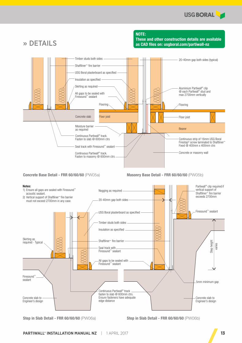
» DETAILS
Concrete Base Detail - FRR 60/60/60 (PW05a)
NOTE: These and other construction details are available as CAD files on: usgboral.com/partiwall-nz
Masonry Base Detail - FRR 60/60/60 (PW05b)
Step in Slab Detail - FRR 60/60/60 (PW06a) Step in Slab Detail - FRR 60/60/60 (PW06b)
Seal track with Firesound™ sealant
20-40mm gap both sides (typical)
Flooring Flooring
Floor joist
Moisture barrieras required
Continuous Partiwall® track. Fasten to masonry @ 600mm ctrs
Floor joist
Bearer
Aluminium Partiwall® clip @ each Partiwall® stud and max 2700mm vertically
Continuous strip of 16mm USG Boral Firestop® screw laminated to Shaftliner™ Fixed @ 400mm x 400mm ctrs
Concrete or masonry wall
USG Boral plasterboard as specified
Timber studs both sides
Insulation as specified
Shaftliner™ fire barrier
Skirting as required
All gaps to be sealed with Firesound™ sealant
Concrete slab
Continuous Partiwall® track. Fasten to slab @ 600mm ctrs
Step
hei
ght
20-40mm gap both sides
Concrete slab to Engineer’s design
Concrete slab to Engineer’s design
5mm minimum gap
Firesound™ sealant
Skirting as required - Typical
USG Boral plasterboard as specified
All gaps to be sealed with Firesound™ sealant
Timber studs both sides
Insulation as specified
Shaftliner™ fire barrier
Seal track with Firesound™ sealant
Continuous Partiwall® track fasten to slab @ 600mm ctrs. Ensure fasteners have adequate edge distance
Notes:1) Ensure all gaps are sealed with Firesound™
acoustic sealant.2) Vertical support of Shaftliner™ fire barrier
must not exceed 2700mm in any case.
Firesound™ sealant
Nogging as requiredPartiwall® clip required if vertical support of Shaftliner™ fire barrier exceeds 2700mm
varie
s
14 1 APRIL 2017 | PARTIWALL® INSTALLATION MANUAL NZ
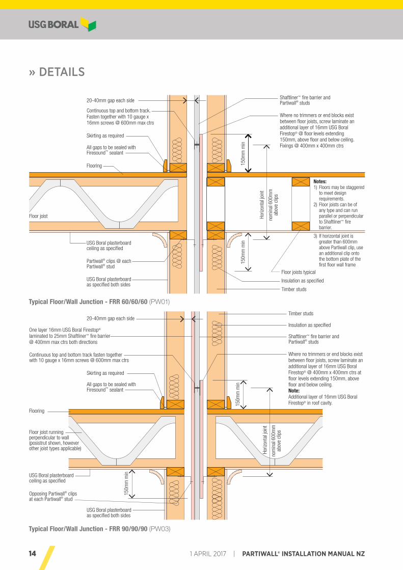
Typical Floor/Wall Junction - FRR 60/60/60 (PW01)
» DETAILS
Typical Floor/Wall Junction - FRR 90/90/90 (PW03)
20-40mm gap each side Shaftliner™ fire barrier and Partiwall® studs
Where no trimmers or end blocks exist between floor joists, screw laminate an additional layer of 16mm USG Boral Firestop® @ floor levels extending 150mm, above floor and below ceiling. Fixings @ 400mm x 400mm ctrs
Floor joists typical
Timber studs
Insulation as specified
Continuous top and bottom track. Fasten together with 10 gauge x 16mm screws @ 600mm max ctrs
Skirting as required
All gaps to be sealed with Firesound™ sealant
Flooring
Floor joist
USG Boral plasterboard ceiling as specified
Partiwall® clips @ each Partiwall® stud
USG Boral plasterboard as specified both sides
Horiz
onta
l joi
nt
nom
inal
600
mm
ab
ove
clip
s
150m
m m
in15
0mm
min
Notes:1) Floors may be staggered
to meet design requirements.
2) Floor joists can be of any type and can run parallel or perpendicular to Shaftliner™ fire barrier.
3) If horizontal joint is greater than 600mm above Partiwall clip, use an additional clip onto the bottom plate of the first floor wall frame
20-40mm gap each side
150m
m m
in
150m
m m
in
Shaftliner™ fire barrier and Partiwall® studs
Where no trimmers or end blocks exist between floor joists, screw laminate an additional layer of 16mm USG Boral Firestop® @ 400mm x 400mm ctrs at floor levels extending 150mm, above floor and below ceiling.Note:Additional layer of 16mm USG Boral Firestop® in roof cavity.
Timber studs
Insulation as specified
Continuous top and bottom track fasten together with 10 gauge x 16mm screws @ 600mm max ctrs
Skirting as required
All gaps to be sealed with Firesound™ sealant
Flooring
Floor joist running perpendicular to wall (posistrut shown, however other joist types applicable)
USG Boral plasterboard ceiling as specified
Opposing Partiwall® clips at each Partiwall® stud
USG Boral plasterboard as specified both sides
One layer 16mm USG Boral Firestop®
laminated to 25mm Shaftliner™ fire barrier @ 400mm max ctrs both directions
Horiz
onta
l joi
nt
nom
inal
600
mm
ab
ove
clip
s
15PARTIWALL® INSTALLATION MANUAL NZ | 1 APRIL 2017
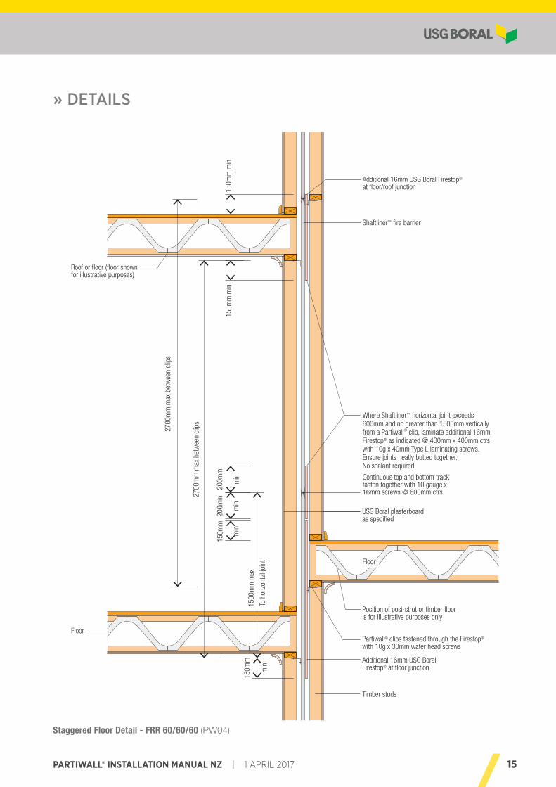
» DETAILS
Staggered Floor Detail - FRR 60/60/60 (PW04)
2700
mm
max
bet
wee
n cl
ips
2700
mm
max
bet
wee
n cl
ips
Roof or floor (floor shown for illustrative purposes)
Timber studs
Additional 16mm USG Boral Firestop® at floor/roof junction
Floor
Shaftliner™ fire barrier
Continuous top and bottom track fasten together with 10 gauge x 16mm screws @ 600mm ctrs
Partiwall® clips fastened through the Firestop®
with 10g x 30mm wafer head screws
Additional 16mm USG Boral Firestop® at floor junction
Position of posi-strut or timber floor is for illustrative purposes only
Where Shaftliner™ horizontal joint exceeds 600mm and no greater than 1500mm vertically from a Partiwall® clip, laminate additional 16mm Firestop® as indicated @ 400mm x 400mm ctrs with 10g x 40mm Type L laminating screws.Ensure joints neatly butted together. No sealant required.
USG Boral plasterboard as specified
150m
m m
in15
0mm
min
200m
m
min
200m
m
min
150m
m
min
1500
mm
max
To h
orizo
ntal
join
t
150m
m
min
3000
mm
max
bet
wee
n cl
ips
3000
mm
max
bet
wee
n cl
ips
Roof or floor (floor shown for illustrative purposes)
Timber studs
Additional 16mm Boral Firestop® at floor/roof junction
Floor
Shaftliner™ fire barrier
Continuous top and bottom track fasten together with 10 gauge screws @ 600mm ctrs
Partition clips
Additional 16mm Boral Firestop® at floor junction
Position of posi-strut or timber floor is for illustrative purposes only
Where Shaftliner™ horizontal joint exceeds 600mm and no greater than 1500mm vertically from a Partiwall® clip, laminate additional 16mm Firestop® as indicated @ 400mm x 400mm ctrs with 10g x 38mm Type L laminating screws
Boral plasterboard as specified
150m
m m
in15
0mm
min
200m
m
min
150m
m
min
1500
mm
max
To h
orizo
ntal
join
t
150m
m
Min
Floor
16 1 APRIL 2017 | PARTIWALL® INSTALLATION MANUAL NZ
» DETAILS
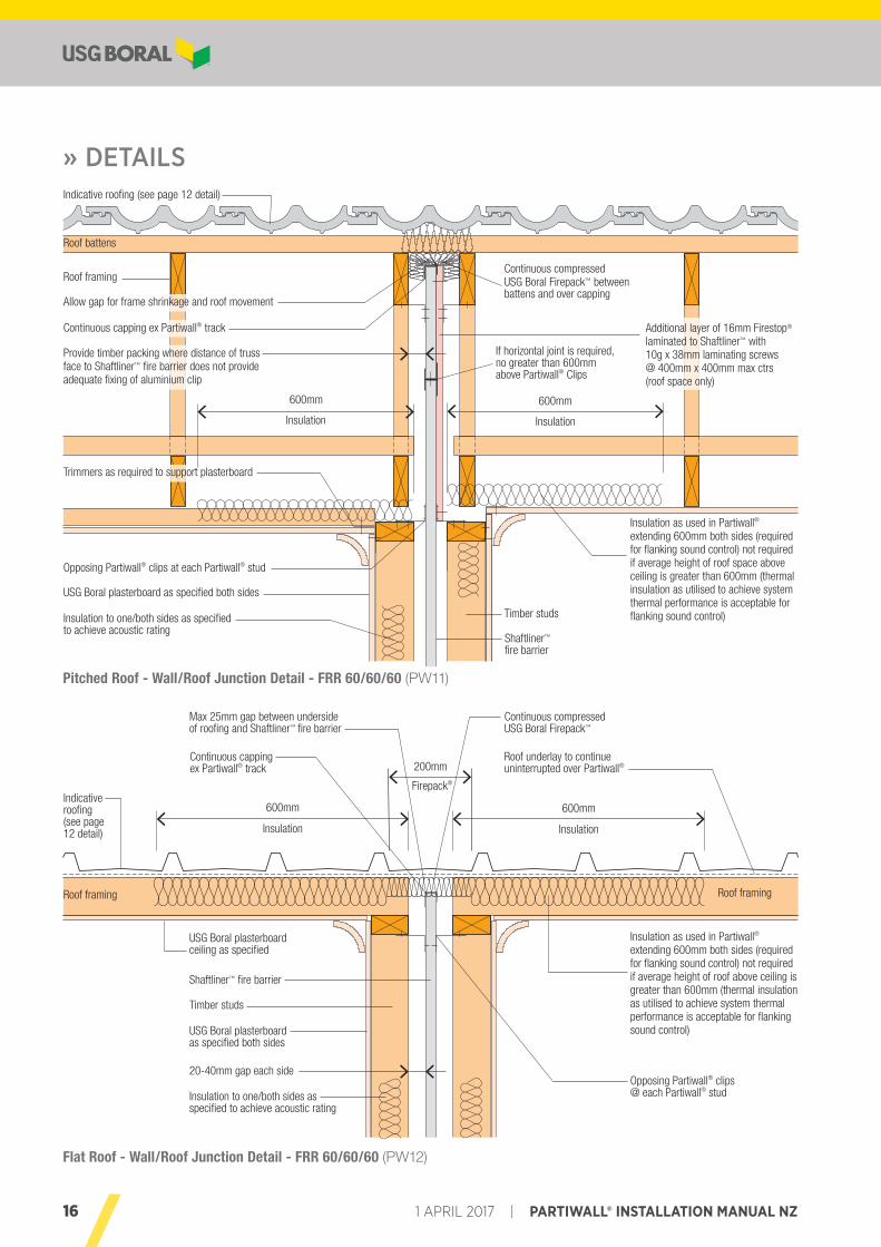
Pitched Roof - Wall/Roof Junction Detail - FRR 60/60/60 (PW11)
Flat Roof - Wall/Roof Junction Detail - FRR 60/60/60 (PW12)
600mm
Insulation
600mm
Insulation
Shaftliner™ fire barrier
Timber studs
Indicative roofing (see page 12 detail)
Roof framing
Roof battens
Insulation to one/both sides as specified to achieve acoustic rating
Insulation as used in Partiwall® extending 600mm both sides (required for flanking sound control) not required if average height of roof space above ceiling is greater than 600mm (thermal insulation as utilised to achieve system thermal performance is acceptable for flanking sound control)
Additional layer of 16mm Firestop® laminated to Shaftliner™ with 10g x 38mm laminating screws @ 400mm x 400mm max ctrs (roof space only)
Continuous compressed USG Boral Firepack™ between battens and over capping
If horizontal joint is required, no greater than 600mm above Partiwall® Clips
Allow gap for frame shrinkage and roof movement
Continuous capping ex Partiwall® track
Provide timber packing where distance of truss face to Shaftliner™ fire barrier does not provide adequate fixing of aluminium clip
Opposing Partiwall® clips at each Partiwall® stud
USG Boral plasterboard as specified both sides
600mm
Insulation
600mm
Insulation
Shaftliner™ fire barrier
Timber studs
Non combustible roofing
Roof framing
Roof battens
Insulation to one/both sides as specified to achieve acoustic rating
Insulation as used in Partiwall® extending 600mm both sides (required for flanking sound control) not required if average height of roof space above ceiling is greater than 600mm (thermal insulation as utilised to achieve system thermal performance is acceptable for flanking sound control)
Additional layer of 16mm Firestop® laminated to Shaftliner™ with 10g x 38mm laminating screws @ 400mm x 400mm max ctrs (roof space only)
Continuous compressed Partiwall® batt between battens and over capping
Allow gap for frame shrinkage and roof movement
Continuous capping ex Partiwall® track
Provide timber packing where distance of truss face to Shaftliner™ fire barrier does not provide adequate fixing of aluminium clip
Opposing Partiwall® clips at each Partiwall® stud
Boral plasterboard as specified both sides
Trimmers as required to support plasterboard
600mm
Insulation
600mm
Insulation
Roof framing
Shaftliner™ fire barrier
Timber studs
USG Boral plasterboard as specified both sides
USG Boral plasterboard ceiling as specified
Insulation to one/both sides as specified to achieve acoustic rating
Opposing Partiwall® clips @ each Partiwall® stud
Insulation as used in Partiwall® extending 600mm both sides (required for flanking sound control) not required if average height of roof above ceiling is greater than 600mm (thermal insulation as utilised to achieve system thermal performance is acceptable for flanking sound control)
Roof underlay to continue uninterrupted over Partiwall®
Continuous compressed USG Boral Firepack™
Max 25mm gap between underside of roofing and Shaftliner™ fire barrier
Continuous capping ex Partiwall® track
Indicative roofing (see page 12 detail)
Roof framing
200mm
Firepack®
20-40mm gap each side
17PARTIWALL® INSTALLATION MANUAL NZ | 1 APRIL 2017
» DETAILS
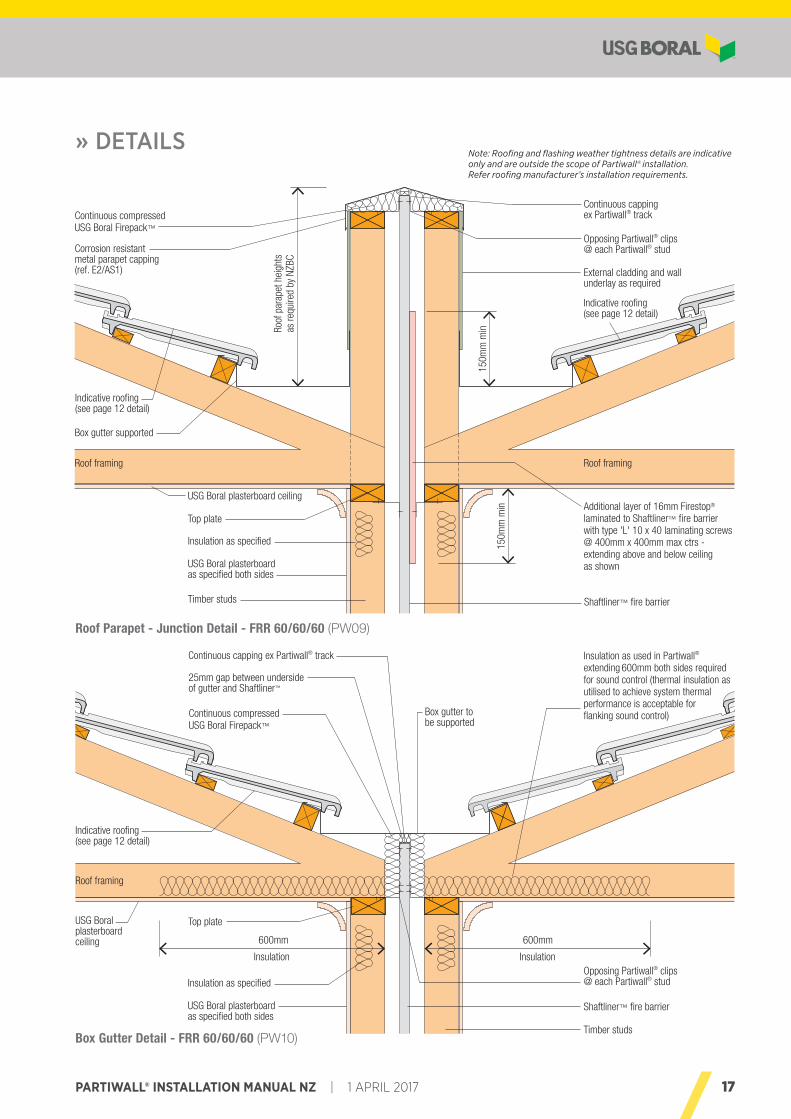
Roof Parapet - Junction Detail - FRR 60/60/60 (PW09)
Roof
par
apet
hei
ghts
as
requ
ired
by N
ZBC
150m
m m
in
Roof framing
150m
m m
in
Corrosion resistant metal parapet capping(ref. E2/AS1)
Indicative roofing (see page 12 detail)
Box gutter supported
Roof framing
USG Boral plasterboard ceiling
Top plate
Insulation as specified
USG Boral plasterboard as specified both sides
Opposing Partiwall® clips @ each Partiwall® stud
External cladding and wall underlay as required
Additional layer of 16mm Firestop® laminated to Shaftliner™ fire barrier with type 'L' 10 x 40 laminating screws @ 400mm x 400mm max ctrs - extending above and below ceiling as shown
Shaftliner™ fire barrierTimber studs
Continuous compressed USG Boral Firepack™
Continuous capping ex Partiwall® track
Indicative roofing (see page 12 detail)
600mm 600mm
Insulation Insulation
25mm gap between underside of gutter and Shaftliner™
Continuous compressed USG Boral Firepack™
Roof framing
USG Boral plasterboard ceiling
Top plate
Insulation as specified
USG Boral plasterboard as specified both sides
Continuous capping ex Partiwall® track Insulation as used in Partiwall® extending 600mm both sides required for sound control (thermal insulation as utilised to achieve system thermal performance is acceptable for flanking sound control)
Opposing Partiwall® clips @ each Partiwall® stud
Shaftliner™ fire barrier
Box gutter to be supported
Timber studs
Indicative roofing (see page 12 detail)
Note: Roofing and flashing weather tightness details are indicative only and are outside the scope of Partiwall® installation. Refer roofing manufacturer’s installation requirements.
Box Gutter Detail - FRR 60/60/60 (PW10)
18 1 APRIL 2017 | PARTIWALL® INSTALLATION MANUAL NZ
» DETAILS
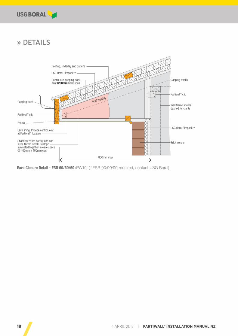
Eave Closure Detail - FRR 60/60/60 (PW19) (if FRR 90/90/90 required, contact USG Boral)
800mm max
Eave lining. Provide control joint at Partiwall® location
Fascia
Partiwall® clip
Capping track Roof framing
Continuous capping track min 1200mm back span
USG Boral Firepack™
Roofing, underlay and battens
Wall frame shown dashed for clarity
Brick veneer
Capping tracks
Partiwall® clip
USG Boral Firepack™
Shaftliner™ fire barrier and one layer 16mm Boral Firestop® laminated together in eave space @ 400mm x 400mm ctrs
19PARTIWALL® INSTALLATION MANUAL NZ | 1 APRIL 2017
» DETAILS
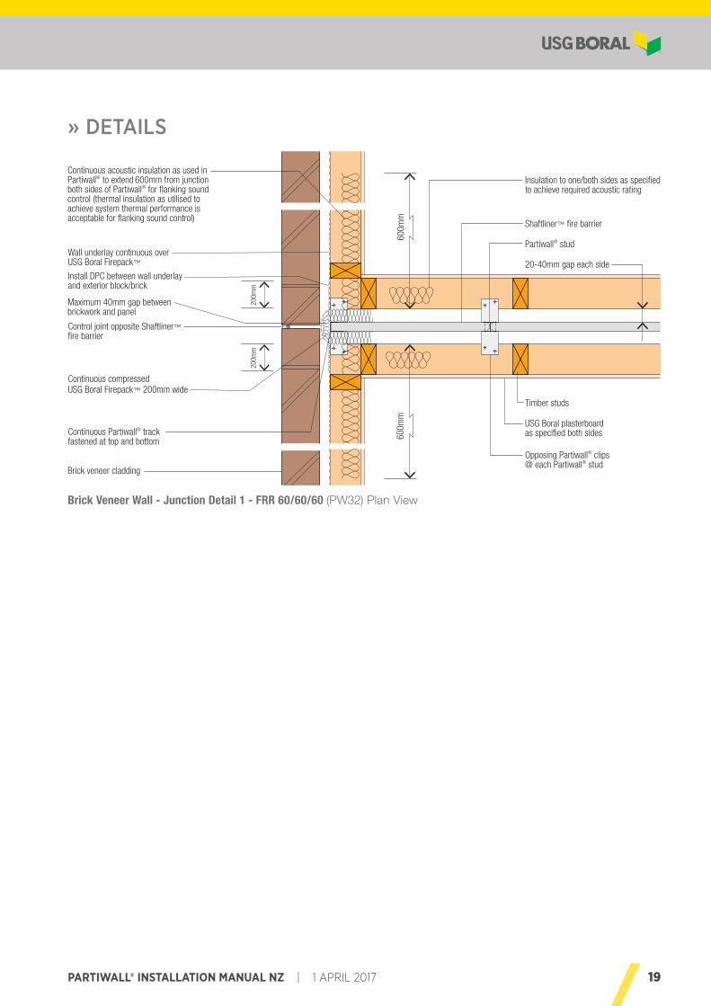
Brick Veneer Wall - Junction Detail 1 - FRR 60/60/60 (PW32) Plan View
20-40mm gap each sideWall underlay continuous over USG Boral Firepack™
Maximum 40mm gap between brickwork and panel
Control joint opposite Shaftliner™ fire barrier
Install DPC between wall underlay and exterior block/brick
Continuous compressed USG Boral Firepack™ 200mm wide
Continuous Partiwall® track fastened at top and bottom
Brick veneer cladding
Opposing Partiwall® clips @ each Partiwall® stud
USG Boral plasterboard as specified both sides
Timber studs
Insulation to one/both sides as specified to achieve required acoustic rating
Partiwall® stud
Shaftliner™ fire barrier
Continuous acoustic insulation as used in Partiwall® to extend 600mm from junction both sides of Partiwall® for flanking sound control (thermal insulation as utilised to achieve system thermal performance is acceptable for flanking sound control)
600m
m
200m
m
600m
m
200m
m
20 1 APRIL 2017 | PARTIWALL® INSTALLATION MANUAL NZ
» DETAILS
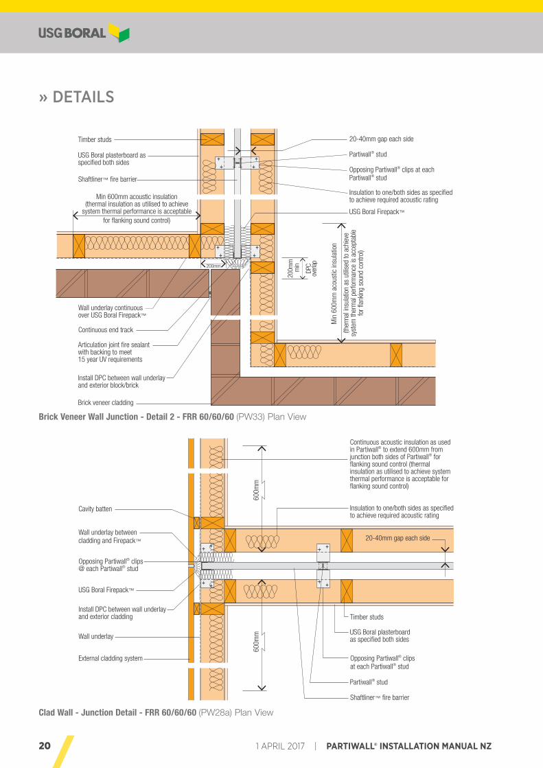
Clad Wall - Junction Detail - FRR 60/60/60 (PW28a) Plan View
Brick Veneer Wall Junction - Detail 2 - FRR 60/60/60 (PW33) Plan View
Min
600
mm
aco
ustic
insu
latio
n
Timber studs
USG Boral plasterboard as specified both sides
Shaftliner™ fire barrier
Articulation joint fire sealant with backing to meet 15 year UV requirements
Install DPC between wall underlay and exterior block/brick
Brick veneer cladding
Partiwall® stud
Opposing Partiwall® clips at each Partiwall® stud
Insulation to one/both sides as specified to achieve required acoustic rating
USG Boral Firepack™
Continuous end track
Wall underlay continuous over USG Boral Firepack™
Min 600mm acoustic insulation(thermal insulation as utilised to achieve
system thermal performance is acceptable for flanking sound control)
(ther
mal
insu
latio
n as
util
ised
to a
chie
ve
syst
em th
erm
al p
erfo
rman
ce is
acc
epta
ble
for fl
anki
ng s
ound
con
trol)
20-40mm gap each side
200m
m m
in
DPC
over
lap200mm
600m
m60
0mm
External cladding system
20-40mm gap each side
Opposing Partiwall® clips @ each Partiwall® stud
USG Boral plasterboard as specified both sides
Timber studs
Insulation to one/both sides as specified to achieve required acoustic rating
Partiwall® stud
Shaftliner™ fire barrier
Continuous acoustic insulation as used in Partiwall® to extend 600mm from junction both sides of Partiwall® for flanking sound control (thermal insulation as utilised to achieve system thermal performance is acceptable for flanking sound control)
Opposing Partiwall® clips at each Partiwall® stud
Wall underlay
USG Boral Firepack™
Cavity batten
Wall underlay between cladding and Firepack™
Install DPC between wall underlay and exterior cladding
21PARTIWALL® INSTALLATION MANUAL NZ | 1 APRIL 2017
» DETAILS
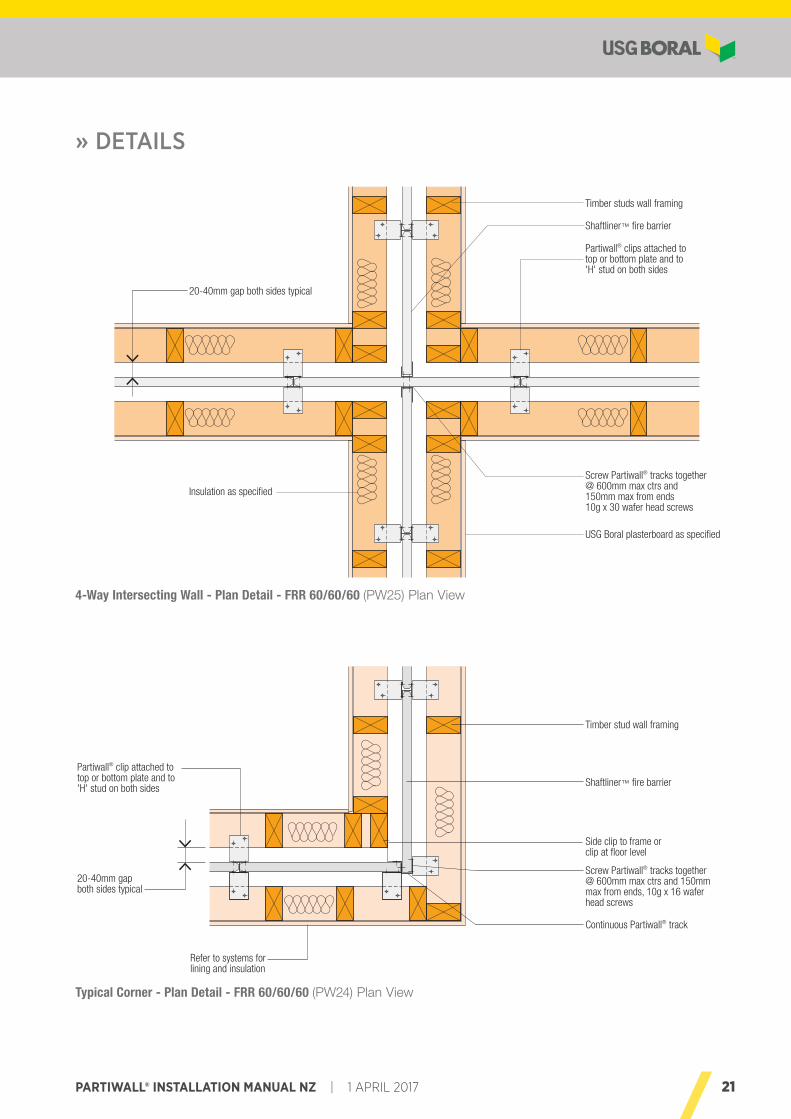
4-Way Intersecting Wall - Plan Detail - FRR 60/60/60 (PW25) Plan View
Typical Corner - Plan Detail - FRR 60/60/60 (PW24) Plan View
Partiwall® clips attached to top or bottom plate and to 'H' stud on both sides
20-40mm gap both sides typical
Screw Partiwall® tracks together @ 600mm max ctrs and 150mm max from ends 10g x 30 wafer head screws
Insulation as specified
Shaftliner™ fire barrier
Timber studs wall framing
USG Boral plasterboard as specified
Screw Partiwall® tracks together @ 600mm max ctrs and 150mm max from ends, 10g x 16 wafer head screws
Refer to systems for lining and insulation
Timber stud wall framing
Shaftliner™ fire barrier
Partiwall® clip attached to top or bottom plate and to 'H' stud on both sides
Side clip to frame or clip at floor level
Continuous Partiwall® track
20-40mm gap both sides typical
22 1 APRIL 2017 | PARTIWALL® INSTALLATION MANUAL NZ
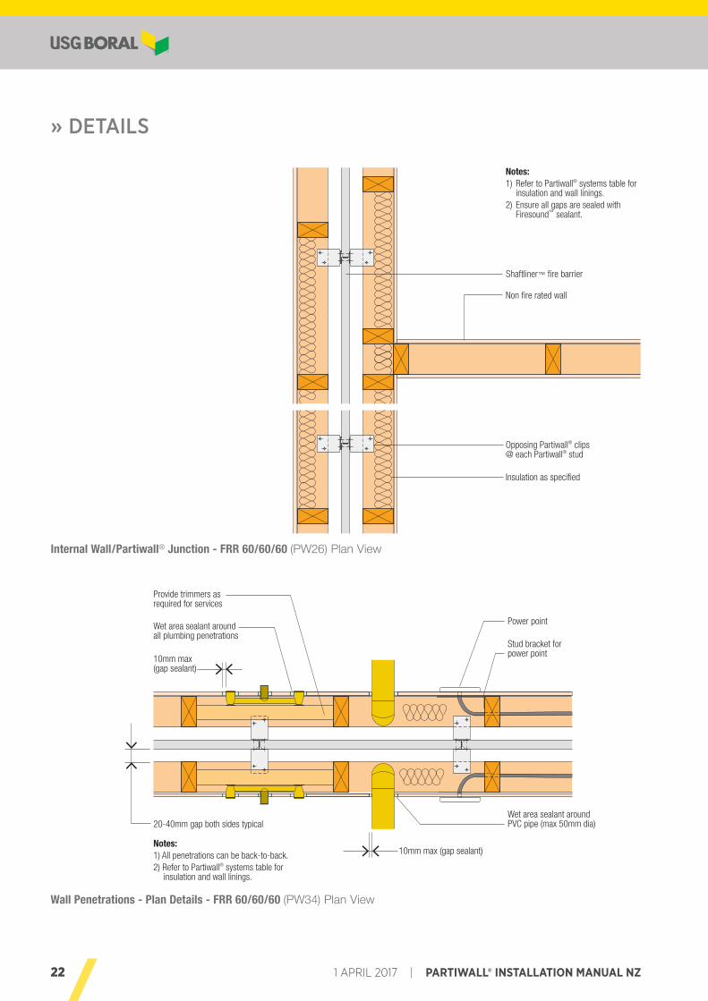
Internal Wall/Partiwall® Junction - FRR 60/60/60 (PW26) Plan View
Wall Penetrations - Plan Details - FRR 60/60/60 (PW34) Plan View
» DETAILS
Power point
Stud bracket for power point
10mm max(gap sealant)
Provide trimmers as required for services
Wet area sealant around all plumbing penetrations
10mm max (gap sealant)
Wet area sealant around PVC pipe (max 50mm dia)20-40mm gap both sides typical
Notes:1) All penetrations can be back-to-back.2) Refer to Partiwall® systems table for
insulation and wall linings.
Shaftliner™ fire barrier
Non fire rated wall
Opposing Partiwall® clips @ each Partiwall® stud
Insulation as specified
Notes:1) Refer to Partiwall® systems table for
insulation and wall linings.2) Ensure all gaps are sealed with
Firesound™ sealant.
23PARTIWALL® INSTALLATION MANUAL NZ | 1 APRIL 2017
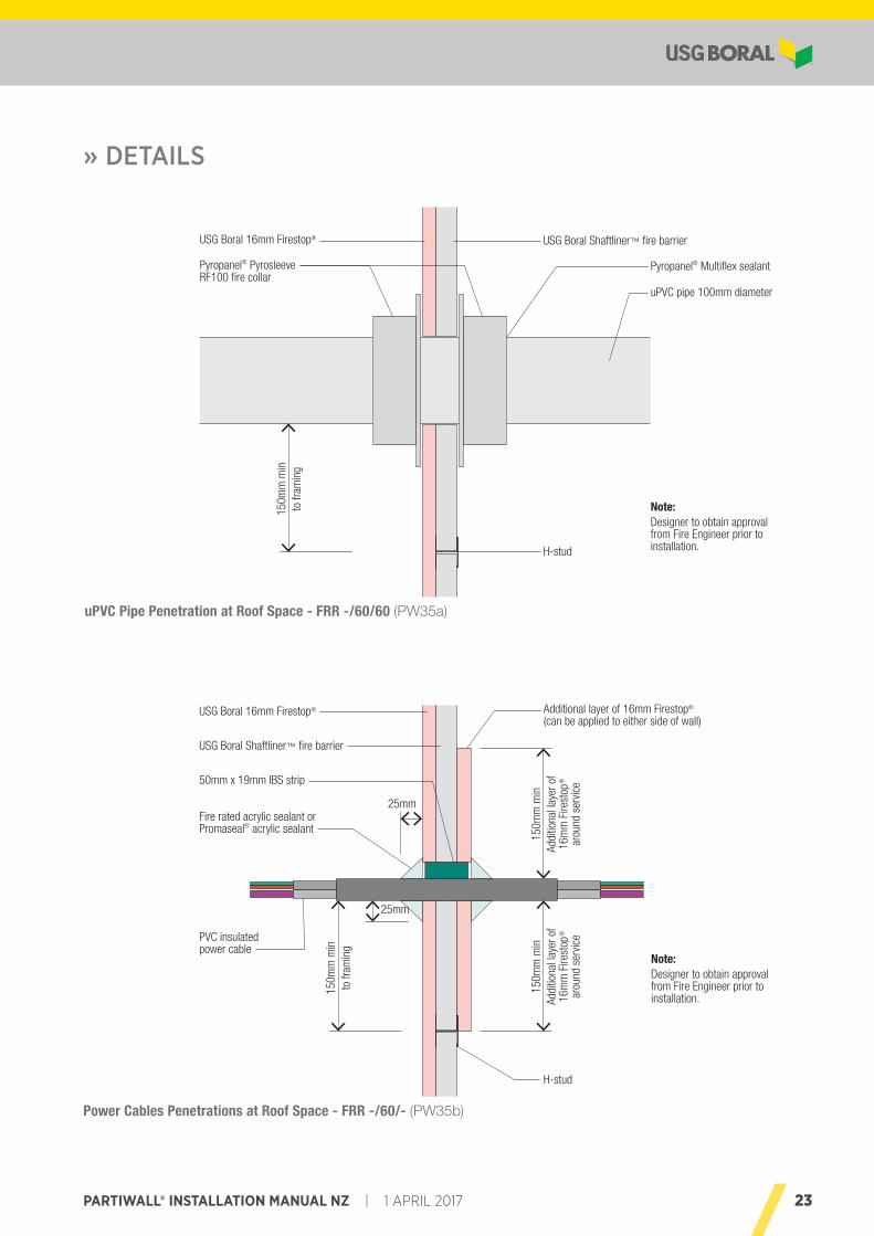
uPVC Pipe Penetration at Roof Space - FRR -/60/60 (PW35a)
Power Cables Penetrations at Roof Space - FRR -/60/- (PW35b)
» DETAILS
USG Boral Shaftliner™ fire barrierUSG Boral 16mm Firestop®
Pyropanel® Multiflex sealantPyropanel® Pyrosleeve RF100 fire collar
uPVC pipe 100mm diameter
Note:Designer to obtain approval from Fire Engineer prior to installation.
150m
m m
in
to fr
amin
g
H-stud
Additional layer of 16mm Firestop® (can be applied to either side of wall)
USG Boral Shaftliner™ fire barrier
USG Boral 16mm Firestop®
150m
m m
inAd
ditio
nal l
ayer
of
16m
m F
irest
op®
arou
nd s
ervic
e
150m
m m
inAd
ditio
nal l
ayer
of
16m
m F
irest
op®
arou
nd s
ervic
e50mm x 19mm IBS strip
Fire rated acrylic sealant or Promaseal® acrylic sealant
PVC insulated power cable
25mm
25mm
H-stud
150m
m m
in
to fr
amin
g
Note:Designer to obtain approval from Fire Engineer prior to installation.
24 1 APRIL 2017 | PARTIWALL® INSTALLATION MANUAL NZ
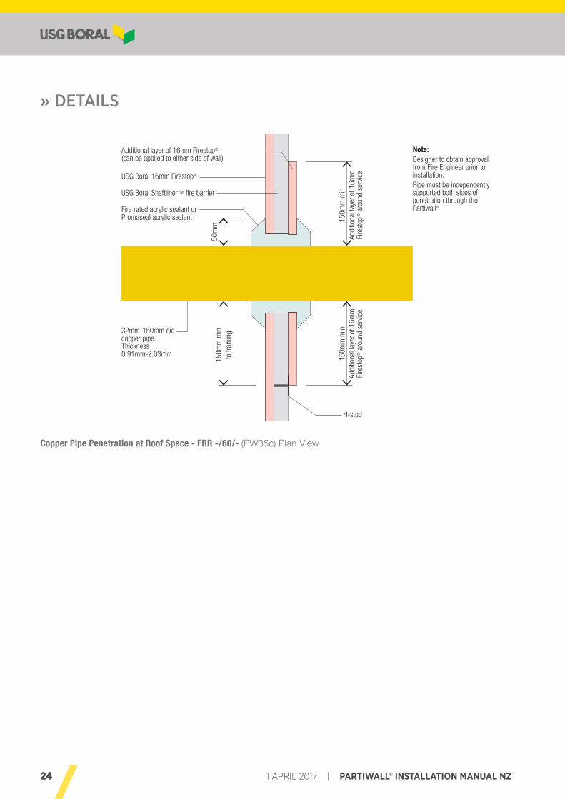
Copper Pipe Penetration at Roof Space - FRR -/60/- (PW35c) Plan View
» DETAILS
150m
m m
in
to fr
amin
g
150m
m m
inAd
ditio
nal l
ayer
of 1
6mm
Fi
rest
op® a
roun
d se
rvic
e
150m
m m
inAd
ditio
nal l
ayer
of 1
6mm
Fi
rest
op® a
roun
d se
rvic
e
USG Boral Shaftliner™ fire barrier
Additional layer of 16mm Firestop® (can be applied to either side of wall)
USG Boral 16mm Firestop®
32mm-150mm dia copper pipe. Thickness 0.91mm-2.03mm
Fire rated acrylic sealant or Promaseal acrylic sealant
50m
m
H-stud
Note:Designer to obtain approval from Fire Engineer prior to installation.Pipe must be independently supported both sides of penetration through the Partiwall®
25PARTIWALL® INSTALLATION MANUAL NZ | 1 APRIL 2017
Installation of the Shaftliner™ fire barrier requires the attachment of the supporting Partiwall® studs to framing members using Partiwall® clips. Set out framing to allow for the required clearances on both sides of the Shaftliner™ fire barrier and later clipping of the Partiwall® studs to wall plates and roof trusses.
After the framing on one side has been completed, the Shaftliner™ fire barrier is installed and clipped to the completed side. When framing on the other side is completed the Shaftliner™ fire barrier is clipped to that side.
The sequence of construction should be planned to accommodate the progressive erection of the Shaftliner™ fire barrier.
DELIVERY, ONSITE HANDLING AND STORAGETo reduce the risk of damage, plasterboard should be delivered to site just prior to installation.
During handling, sheets should be carried in an ‘upright’ position with particular care taken to protect the edges.
Plasterboard should be stored in neat, flat stacks off the ground/floor in a dry covered area. This will prevent sagging and minimise damage to board edges and surfaces.
INSTALLATION OF SHAFTLINER™ FIRE BARRIER
DO’S • Do use Partiwall® clips at every Partiwall® stud and not
more than 2700mm above lower clip line or base track.
• Do locate and fix down bottom track adequately.
• Do seal at bottom track.
• Do install USG Boral Firepack™ at wall ends and top, as specified.
• Do cut Partiwall® stud and Shaftliner™ panels to the same length.
• Do insert Partiwall® stud and Shaftliner™ fully into the base track.
• Do insert Shaftliner™ panels fully into the Partiwall® studs.
• Do use the specified fasteners for the aluminium Partiwall®
clips.
DON’TS • Don’t use damaged materials.
• Don’t penetrate the Shaftliner™ other than in the roof space as per USG Boral’s details.
• Don’t exceed specified clip spacing.
• Don’t use steel clips.
• Don’t position track 6mm gap under Partiwall® studs. Tracks should be used in full lengths.
• Don’t run services in the gap between Shaftliner™ fire barrier and framework.
• Don’t use Partiwall® H-stud in lieu of Partiwall® track as edge capping nor as horizontal joint in Shaftliner™ fire barrier.
If storing outdoors, stack sheets on a level, moisture-free platform, and keep fully protected from the weather. Ensure the platform can support a load up to 800kg/m3 density.
Plasterboard stacking supports when not on pallets should be spaced at 600mm centres.
PROTECTION FROM WEATHERTo prevent damage from the weather all materials must be suitably protected during construction.
Shaftliner™ fire barrier and Firestop® must not be exposed to the weather for longer than 30 days (one month) when installed. Where exposure is likely to be longer or where heavy rain is predicted temporary (protection) cover should be used.
Internal lining shall not take place until the Shaftliner™ is dry and framing moisture content is less than 18%.
Temporary exposure of Shaftliner™ fire barrier to moisture should not downgrade its fire resisting properties as long as there is no physical damage to the panels in a wet state.
USG Boral also recommends that concrete slabs on which the Shaftliner™ fire barrier is erected should be level, free draining, and free of depressions where water can collect, removing the possibility of the panel standing in the water for any length of time. The specified 6mm gap between the adjacent bottom track lengths will facilitate drainage of water from the track.
26 1 APRIL 2017 | PARTIWALL® INSTALLATION MANUAL NZ
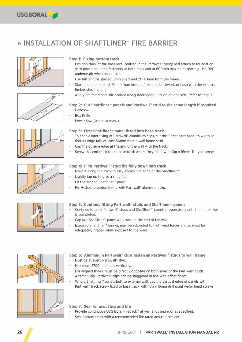
Step 2: Cut Shaftliner™ panels and Partiwall® stud to the same length if required • Handsaw • Box Knife • Power Saw (use dust mask)
Step 4: First Partiwall® stud fits fully down into track • Move it along the track to fully encase the edge of the Shaftliner™. • Lightly tap up to give a snug fit. • Fit the second Shaftliner™ panel. • Fix H-stud to timber frame with Partiwall® aluminium clip.
Step 6: Aluminium Partiwall® clips fasten all Partiwall® studs to wall frame • Must be at every Partiwall® stud. • Maximum 2700mm apart vertically. • For aligned floors, must be directly opposite on both sides of the Partiwall® studs.
Alternatively, Partiwall® clips can be staggered in line with offset floors. • Where Shaftliner™ panels butt to external wall, cap the vertical edge of panels with
Partiwall® track screw fixed to base track with 10g x 16mm drill point wafer head screws.
Step 5: Continue fitting Partiwall® studs and Shaftliner™ panels • Continue to erect Partiwall® studs and Shaftliner™ panels progressively until the fire barrier
is completed. • Cap last Shaftliner™ panel with track at the end of the wall. • Exposed Shaftliner™ barrier, may be subjected to high wind forces and so must be
adequately braced while exposed to the wind.
Step 3: First Shaftliner™ panel fitted into base track • To enable later fixing of Partiwall® aluminium clips, cut this Shaftliner™ panel to width so
that its edge falls at least 50mm from a wall frame stud. • Cap the outside edge at the end of the wall with the track. • Screw this end track to the base track where they meet with 10g x 16mm ‘D’ type screw.
Step 7: Seal for acoustics and fire • Provide continuous USG Boral Firepack™ at wall ends and roof as specified. • Seal bottom track with a recommended fire rated acoustic sealant.
» INSTALLATION OF SHAFTLINER™ FIRE BARRIER
Step 1: Fixing bottom track • Position track at the base level centred in the Partiwall® cavity and attach to foundation
with power actuated fasteners at both ends and at 600mm maximum spacing. Use DPC underneath when on concrete
• Use full lengths spaced 6mm apart and 20-40mm from the frame. • Start and end nominal 40mm from inside of external brickwork or flush with the external
timber stud framing. • Apply fire rated acoustic sealant along track/floor junction on one side. Refer to Step 7.
Equal
27PARTIWALL® INSTALLATION MANUAL NZ | 1 APRIL 2017
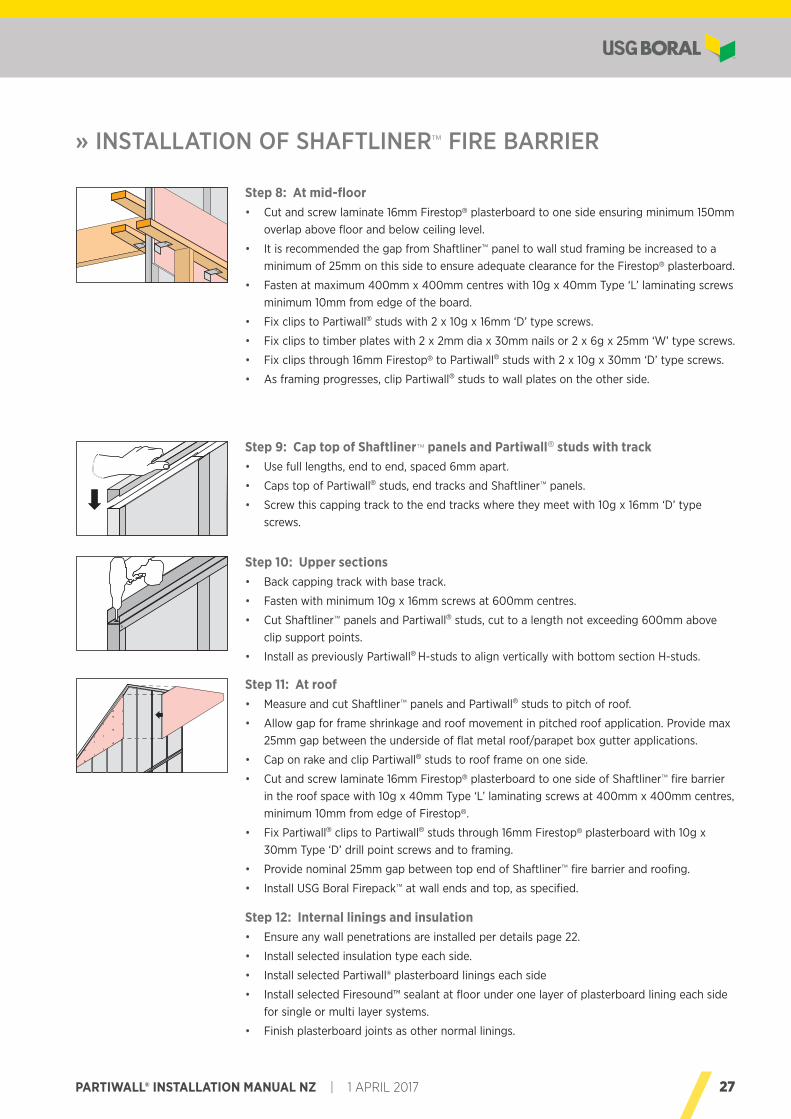
Step 10: Upper sections • Back capping track with base track.
• Fasten with minimum 10g x 16mm screws at 600mm centres.
• Cut Shaftliner™ panels and Partiwall® studs, cut to a length not exceeding 600mm above clip support points.
• Install as previously Partiwall® H-studs to align vertically with bottom section H-studs.
Step 12: Internal linings and insulation • Ensure any wall penetrations are installed per details page 22.
• Install selected insulation type each side.
• Install selected Partiwall® plasterboard linings each side
• Install selected Firesound™ sealant at floor under one layer of plasterboard lining each side for single or multi layer systems.
• Finish plasterboard joints as other normal linings.
Step 11: At roof • Measure and cut Shaftliner™ panels and Partiwall® studs to pitch of roof.
• Allow gap for frame shrinkage and roof movement in pitched roof application. Provide max 25mm gap between the underside of flat metal roof/parapet box gutter applications.
• Cap on rake and clip Partiwall® studs to roof frame on one side.
• Cut and screw laminate 16mm Firestop® plasterboard to one side of Shaftliner™ fire barrier in the roof space with 10g x 40mm Type ‘L’ laminating screws at 400mm x 400mm centres, minimum 10mm from edge of Firestop®.
• Fix Partiwall® clips to Partiwall® studs through 16mm Firestop® plasterboard with 10g x 30mm Type ‘D’ drill point screws and to framing.
• Provide nominal 25mm gap between top end of Shaftliner™ fire barrier and roofing.
• Install USG Boral Firepack™ at wall ends and top, as specified.
Step 9: Cap top of Shaftliner™ panels and Partiwall® studs with track • Use full lengths, end to end, spaced 6mm apart.
• Caps top of Partiwall® studs, end tracks and Shaftliner™ panels.
• Screw this capping track to the end tracks where they meet with 10g x 16mm ‘D’ type screws.
» INSTALLATION OF SHAFTLINER™ FIRE BARRIER
Step 8: At mid-floor • Cut and screw laminate 16mm Firestop® plasterboard to one side ensuring minimum 150mm
overlap above floor and below ceiling level.
• It is recommended the gap from Shaftliner™ panel to wall stud framing be increased to a minimum of 25mm on this side to ensure adequate clearance for the Firestop® plasterboard.
• Fasten at maximum 400mm x 400mm centres with 10g x 40mm Type ‘L’ laminating screws minimum 10mm from edge of the board.
• Fix clips to Partiwall® studs with 2 x 10g x 16mm ‘D’ type screws.
• Fix clips to timber plates with 2 x 2mm dia x 30mm nails or 2 x 6g x 25mm ‘W’ type screws.
• Fix clips through 16mm Firestop® to Partiwall® studs with 2 x 10g x 30mm ‘D’ type screws.
• As framing progresses, clip Partiwall® studs to wall plates on the other side.
28 1 APRIL 2017 | PARTIWALL® INSTALLATION MANUAL NZ
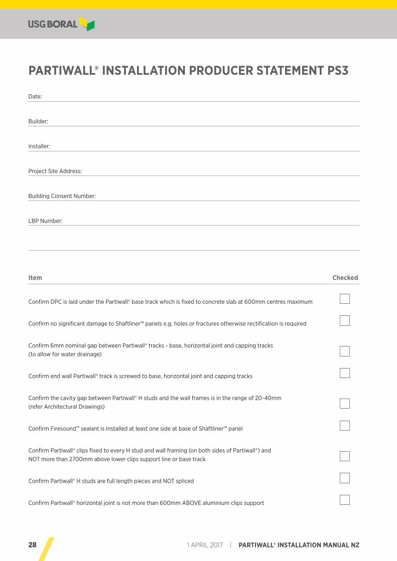
Date:
Builder:
Installer:
Project Site Address:
Building Consent Number:
LBP Number:
Item Checked
Confirm DPC is laid under the Partiwall® base track which is fixed to concrete slab at 600mm centres maximum
Confirm no significant damage to Shaftliner™ panels e.g. holes or fractures otherwise rectification is required
Confirm 6mm nominal gap between Partiwall® tracks - base, horizontal joint and capping tracks (to allow for water drainage)
Confirm end wall Partiwall® track is screwed to base, horizontal joint and capping tracks
Confirm the cavity gap between Partiwall® H studs and the wall frames is in the range of 20-40mm (refer Architectural Drawings)
Confirm Firesound™ sealant is installed at least one side at base of Shaftliner™ panel
Confirm Partiwall® clips fixed to every H stud and wall framing (on both sides of Partiwall®) and NOT more than 2700mm above lower clips support line or base track
Confirm Partiwall® H studs are full length pieces and NOT spliced
Confirm Partiwall® horizontal joint is not more than 600mm ABOVE aluminium clips support
PARTIWALL® INSTALLATION PRODUCER STATEMENT PS3
29PARTIWALL® INSTALLATION MANUAL NZ | 1 APRIL 2017
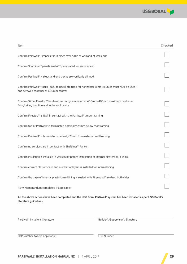
Item Checked
Confirm Partiwall® Firepack™ is in place over ridge of wall and at wall ends
Confirm Shaftliner™ panels are NOT penetrated for services etc
Confirm Partiwall® H studs and end tracks are vertically aligned
Confirm Partiwall® tracks (back to back) are used for horizontal joints (H Studs must NOT be used) and screwed together at 600mm centres
Confirm 16mm Firestop™ has been correctly laminated at 400mmx400mm maximum centres at floor/ceiling junction and in the roof cavity
Confirm Firestop™ is NOT in contact with the Partiwall® timber framing
Confirm top of Partiwall® is terminated nominally 25mm below roof framing
Confirm Partiwall® is terminated nominally 25mm from external wall framing
Confirm no services are in contact with Shaftliner™ Panels
Confirm insulation is installed in wall cavity before installation of internal plasterboard lining
Confirm correct plasterboard and number of layers is installed for internal lining
Confirm the base of internal plasterboard lining is sealed with Firesound™ sealant, both sides
RBW Memorandum completed if applicable
All the above actions have been completed and the USG Boral Partiwall® system has been installed as per USG Boral’s literature guidelines.
Partiwall® Installer’s Signature Builder’s/Supervisor’s Signature
LBP Number (where applicable) LBP Number

30 1 APRIL 2017 | PARTIWALL® INSTALLATION MANUAL NZ
NOTES

31PARTIWALL® INSTALLATION MANUAL NZ | 1 APRIL 2017
NOTES

TECHNICAL ENQUIRIES 0800 USGBORAL FOR NZUSG Boral provides technical advice to Builders, Architects, Contractors, Engineers, Regulators and Home Owners throughout New Zealand.
Our friendly team can offer both practical and design input at all levels of the plasterboard industry. Get your next project off on the right track by contacting USG Boral weekdays 8.30am - 5.00pm on 0800 USGBORAL (0800 874 267).
HEALTH AND SAFETYFor information regarding the safe use of USG Boral Plasterboard products and accessories please refer to instructions on the product packaging or contact your local USG Boral Sales Office or TecASSIST® for a current copy of the Material Safety Data Sheet.
SUSTAINABILITYUSG Boral aims to minimise the environmental impact of its operations and to make a positive difference to the environment and communities in which it operates. Plasterboard is manufactured from abundant natural gypsum resources and 100% recycled paper liner.
www.usgboral.com PB200/3 1 APRIL 2017
This Technical Information Guide is intended to provide general information and should not be used as a substitute for professional advice. There are many variables that can influence construction projects which affect whether a particular construction technique is appropriate. Before proceeding with any project we recommend you obtain professional advice to ascertain the appropriate construction techniques to suit the particular circumstances of your project having regard to the contents of this Installation Manual. We recommend you use qualified tradespersons to install this system.
The technical information contained in this manual was correct at the time of printing. Building systems, details and product availability are, however, subject to change. To ensure the
information you are using is current, USG Boral recommends you review the latest building information available on the USG Boral website. For further information contact TecASSIST® or your nearest USG Boral Sales Office.
© 2017 USG BORAL. All rights reserved. The trademarks USG BORAL, INNOVATION INSPIRED BY YOU, Soundstop, Firestop, Partiwall, Wet Area, Multistop, Shaftliner, Firepack TecASSIST, are trademarks or registered trademarks of USG Boral Building Products or one or more of its affiliates. SHEETROCK, Fiberock, Aqua-Tough are trademarks or registered trademarks owned by United States Gypsum Company and used under license. Firesound is the trademark of H B Fuller. Pyropanel is the registered trademark of Pyropanel Developments Pty Ltd. Promaseal is the registered trademark of Promat.
SALES ENQUIRIES Auckland (09) 270-2595
Wellington (04) 560-4528
Christchurch (03) 365-4245