Embed Size (px)
Citation preview
power
®
2 - c h a n n e l
2 - c h a n n e l
t r a n s • a n a
t r a n s • a n a
t r a n s • a n a
t r a n s • n o v a
4 - c h a n n e l
2 - c h a n n e l
2 - c h a n n e lt r a n s • a n a
4 - c h a n n e lt r a n s • a n a
Power AMPLIFIERINSTALLATION & OPERATION
® ®
c a r a u d i of a n a t i c sfor
POW
ER 3
60 P
OWER
400
POW
ER 5
00 P
OWER
800
POW
ER 8
00 P
OWER
100
0 2
-cha
nnel
4-c
hann
el 2
-cha
nnel
2-c
hann
el 4
-cha
nnel
2-c
hann
elD
ynam
ic P
ower
Rat
ing
(IHF-2
02 St
anda
rd) -
Meas
ured a
t 14.
4 Vo
ltsM
ono
into
a 4
Ω L
oad
481
Wat
ts x
123
2 W
atts
x 2
710
Wat
ts x
196
0 W
atts
x 1
525
Wat
ts x
2
1
460
Wat
ts x
1Pe
r cha
nnel
into
a 2
Ω L
oad
242
Wat
ts x
212
7 W
atts
x 4
330
Wat
ts x
248
0 W
atts
x 2
270
Wat
ts x
4
730
Wat
ts x
2Pe
r cha
nnel
into
a 4
Ω L
oad
154
Wat
ts x
2 8
4 W
atts
x 4
210
Wat
ts x
224
0 W
atts
x 2
150
Wat
ts x
4
450
Wat
ts x
2
Cont
inuo
us P
ower
Rat
ing
(Com
petiti
on St
anda
rd) -
Meas
ured a
t 13.
8 Ba
ttery
Volts
RMS
cont
inuo
us p
ower
per
cha
nnel
, 9
0 W
atts
x 2
50
Wat
ts x
412
5 W
atts
x 2
200
Wat
ts x
210
0 W
atts
x 4
250
Wat
ts x
2bo
th c
hann
els
driv
en in
to a
4Ω
load
from
20
to 2
0,00
0 H
z w
ith le
ss th
an0.
05%
Total
Harm
onic
Disto
rtion (
THD)
RMS
cont
inuo
us p
ower
per
cha
nnel
,18
0 W
atts
x 2
100
Wat
ts x
425
0 W
atts
x 2
400
Wat
ts x
220
0 W
atts
x 4
500
Wat
ts x
2bo
th c
hann
els
driv
en in
to a
2Ω
load
from
20
to 2
0,00
0 H
z, w
ith le
ss th
an0.
1% To
tal H
armon
ic Di
stortio
n (TH
D)
RMS
cont
inuo
us p
ower
mon
o in
to a
360
Wat
ts x
120
0 W
atts
x 2
500
Wat
ts x
180
0 W
atts
x 1
400
Wat
ts x
2
1000
Wat
ts x
14Ω
load
from
20
to 2
0,00
0 H
z, w
ithles
s tha
n 0.1
% To
tal H
armon
ic Di
stortio
n (TH
D)
Sign
al-to
-Noi
se R
atio
(A-
wei
ghte
d) >
100d
B >
100d
B
>
100d
B >
100d
B
>100
dB >
100d
BCr
osso
ver S
lope
(Bu
tterw
orth
)24
dB/o
ctav
e24
dB/o
ctav
e24
dB/o
ctav
e24
dB/o
ctav
e
2
4dB/
octa
ve
24d
B/oc
tave
Cros
sove
r Fre
quen
cy50
Hz –
210
Hz50
Hz –
210
Hz50
Hz –
210
Hz50
Hz –
210
Hz
50Hz
– 2
10Hz
5
0Hz
– 21
0Hz
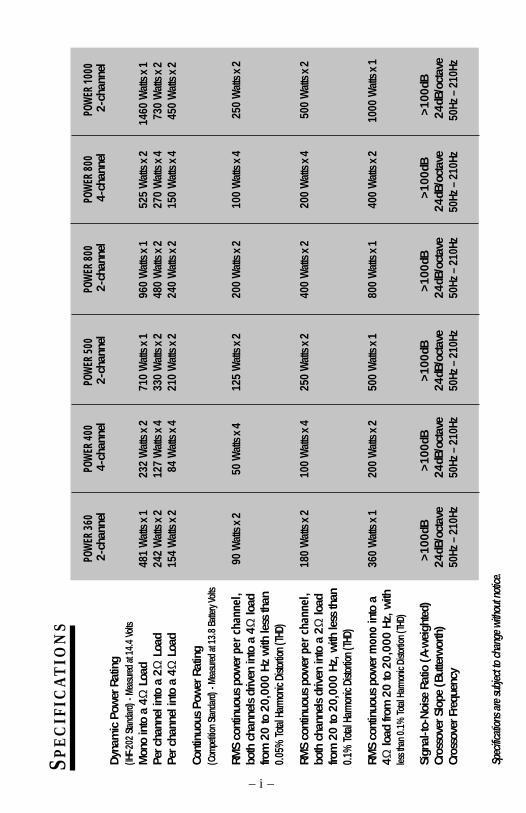
Spec
ificati
ons a
re su
bject
to ch
ange
with
out n
otice
.
SPE
CI F
ICA
TIO
NS
– i –
POW
ER 3
60 P
OWER
400
POW
ER 5
00 P
OWER
800
POW
ER 8
00 P
OWER
100
0 2
-cha
nnel
4-c
hann
el 2
-cha
nnel
2-c
hann
el 4
-cha
nnel
2-c
hann
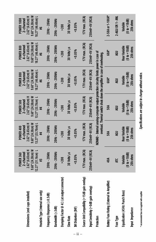
elDi
men
sions
(end
caps
insta
lled)
2.62"
(6.65
cm) H
2.62"
(6.65
cm) H
2.62"
(6.65
cm) H
2.62
" (6.6
5cm)
H2.6
2" (6
.65cm
) H2.6
2" (6
.65cm
) H
9.6
0" (2
4.38c
m) W
9.60
" (24
.38cm
) W
9
.60" (
24.38
cm) W
9.60
" (24
.38cm
) W
9
.60" (
24.38
cm) W
9.60
" (24
.38cm
) W
12.2
7" (3
1.16c
m) L
13.27
" (33
.70cm
) L
13.2
7" (3
3.70c
m) L
18.27
" (46
.40cm
) L
18
.27" (
46.40
cm) L
18.27
" (46
.40cm
) LHe
atsink
Type
(inte
rnal
use o
nly)
#3
#4
#4
#
6
#
6
#6
Frequ
ency
Res
pons
e (±0
.5dB
)20
Hz -
20kH
z20
Hz -
20kH
z20
Hz -
20kH
z20
Hz -
20kH
z20
Hz -
20kH
z20
Hz -
20kH
z
Band
width
( ±3d
B)
20H
z - 2
00kH
z
20Hz
- 20
0kHz
2
0Hz -
200
kHz
2
0Hz -
200
kHz
20
Hz -
200k
Hz
20H
z - 2
00kH
z
Dam
ping
Facto
r @ 4
Ω (a
t outp
ut co
nnec
tor)
>200
>
200
>
200
>
200
>
200
>
200
Slew
Rate
30
Volt
s/ µs
30
Volts
/ µs
30
Volts
/ µs
30
Volts
/ µs
30
Volts
/ µs
30
Volts
/ µs
IM D
istor
tion
(IHF)
<
0.05
%
<0.
05%
<0
.05%
<0
.05%
<0
.05%
<0
.05%
Sourc
e Unit
Com
patib
ility (
+15d
B ga
in ov
erlap
)17
V m
ax. (
RCA)
17V
max
. (RC
A)17
V m
ax. (
RCA)
17V
max
. (RC
A)17
V m
ax. (
RCA)
17V
max
. (RC
A)
Input
Sens
itivity
(+0d
B ga
in ov
erlap
)
250
mV~
4V (R
CA)
250m
V~4V
(RCA
)
250
mV~
4V (R
CA)
250m
V~4V
(RCA
)
250
mV~
4V (R
CA)
250m
V~4V
(RCA
)
Prote
ction
N
OMAD
- Int
ernal
analo
g-co
mpu
ter o
utput
prote
ction
circu
itry lim
its p
ower
in ca
se o
f
o
verlo
ad. T
herm
al sw
itch
shuts
dow
n the
am
plifie
r in
case
of o
verh
eatin
g.
Batte
ry Fu
se R
ating
(Exte
rnal
to Am
plifie
r)
4
0A
5
0A
50
A
60
A*
6
0A*
2-
50A
or 1
-100
A*
Fuse
Type
ATC
AGU
AGU
AGU
AGU
2-A
GU O
R 1-
ANL
Equa
lizati
on (4
5Hz P
unch
Bas
s)
Var
iable
Rear
Var
iable
V
ariab
le
Var
iable
Rear
Var
iable
V
ariab
le (0
to +
18dB
)(0
to +
18dB
)
(0
to +
18dB
)
(
0 to
+18d
B) (0
to +
18dB
) (0
to +
18dB
)Inp
ut Im
peda
nce
20
k ohm
s
20k o
hms
2
0k o
hms
20
k ohm
s
20k
ohm
s
20k
ohm
s
* rec
omm
ende
d fus
e not
supp
lied
with
ampli
fier
Spe
cifica
tions
are
subje
ct to
chan
ge w
ithou
t noti
ce.
– ii –

Dear Customer,
Congratulations on your purchase of the world's finest brand of car audio amplifiers.At Rockford Fosgate we are fanatics about musical reproduction at its best, and we arepleased you chose our product. Through years of engineering expertise, hand craftsman-ship and critical testing procedures, we have created a wide range of products thatreproduce music with all the clarity and richness you deserve.
For maximum performance we recommend you have your new Rockford Fosgateproduct installed by an Authorized Rockford Fosgate Dealer, as we provide specializedtraining through Rockford Technical Training Institute (RTTI). Please read yourwarranty and retain your receipt and original carton for possible future use.
Great product and competent installations are only a piece of the puzzle when it comesto your system. Make sure that your installer is using 100% authentic installationaccessories from Connecting Punch in your installation. Connecting Punch haseverything from RCA cables and speaker wire to Power line and battery connectors.Insist on it! After all, your new system deserves nothing but the best.
To add the finishing touch to your new Rockford Fosgate image order your Rockfordwearables, which include everything from T-shirts and jackets to hats and sunglasses.
To get a free brochure on Rockford Fosgate products and Rockford accessories, in theU.S. call 480-967-3565 or FAX 480-967-8132. For all other countries, call +001-480-967-3565 or FAX +001-480-967-8132.
If, after reading your manual, you still have questions regarding this product,we recommend that you see your Rockford Fosgate dealer. If you need furtherassistance, you can call us direct at 1-800-669-9899. Be sure to have your serialnumber, model number and date of purchase available when you call.
PRACTICE SAFE SOUND™CONTINUOUS EXPOSURE TO SOUND PRESSURE LEVELS OVER 100dB
MAY CAUSE PERMANENT HEARING LOSS. HIGH POWERED AUTOSOUND
SYSTEMS MAY PRODUCE SOUND PRESSURE LEVELS WELL OVER
130dB. USE COMMON SENSE AND PRACTICE SAFE SOUND.
The serial number can be found on the outside of the box. Please record it inthe space provided below as your permanent record. This will serve asverification of your factory warranty and may become useful in recovering youramplifier if it is ever stolen.
Serial Number: ________________________________
Model Number: ________________________________
– iii –

TABLE OF CONTENTS
Specifications.............................................................................................. iIntroduction ................................................................................................ 1Power Amplifier Accessory Pack ................................................................... 1Feature Chart .............................................................................................. 2Design Features .......................................................................................... 3Installation Considerations ........................................................................... 7Mounting Location ...................................................................................... 8Battery and Charging .................................................................................. 9Wiring the System ....................................................................................... 9Using Passive Crossovers ........................................................................... 11Table of Component Values ........................................................................ 12Installation ............................................................................................... 13Operation ................................................................................................. 21System Diagrams ...................................................................................... 24Troubleshooting ........................................................................................ 28Dynamic Power Measurements ................................................................... 31
Warranty Information ................................................................................ 33International Information ............................................................................ 34
Sections markedADVANCED OPERATION
include in-depthtechnical information
Sections markedTROUBLESHOOTING
include recommendations forcuring installation problems
Sections markedINSTALLATION
include “slam dunk”wiring connections
INSTALLATION
+ -+ - TROUBLE-SHOOTING?
Welcome to Rockford Fosgate! This manual is designed to provide informationfor the owner, salesperson and installer. For those of you who want quickinformation on how to install this product, please turn to the InstallationSection of this manual or refer to the icons listed below. Other information canbe located by using the Table of Contents. We, at Rockford Fosgate, haveworked very hard to make sure all the information in this manual is current. But,as we are constantly finding new ways to improve our product, this informationis subject to change without notice.
G E T T I N G S T A R T E D
advanced
Operation
+
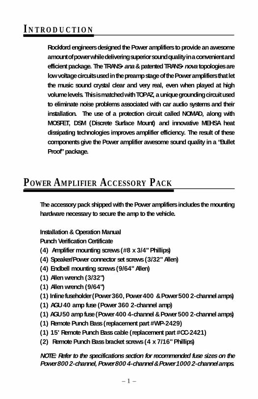
I N T R O D U C T I O N
Rockford engineers designed the Power amplifiers to provide an awesomeamount of power while delivering superior sound quality in a convenient andefficient package. The TRANS•ana & patented TRANS•nova topologies arelow voltage circuits used in the preamp stage of the Power amplifiers that letthe music sound crystal clear and very real, even when played at highvolume levels. This is matched with TOPAZ, a unique grounding circuit usedto eliminate noise problems associated with car audio systems and theirinstallation. The use of a protection circuit called NOMAD, along withMOSFET, DSM (Discrete Surface Mount) and innovative MEHSA heatdissipating technologies improves amplifier efficiency. The result of thesecomponents give the Power amplifier awesome sound quality in a “BulletProof” package.
– 1 –
POWER AMPLIFIER ACCESSORY PACK
The accessory pack shipped with the Power amplifiers includes the mountinghardware necessary to secure the amp to the vehicle.
Installation & Operation ManualPunch Verification Certificate(4) Amplifier mounting screws (#8 x 3/4" Phillips)(4) Speaker/Power connector set screws (3/32" Allen)(4) Endbell mounting screws (9/64" Allen)(1) Allen wrench (3/32")(1) Allen wrench (9/64")(1) Inline fuseholder (Power 360, Power 400 & Power 500 2-channel amps)(1) AGU 40 amp fuse (Power 360 2-channel amp)(1) AGU 50 amp fuse (Power 400 4-channel & Power 500 2-channel amps)(1) Remote Punch Bass (replacement part #WP-2429)(1) 15' Remote Punch Bass cable (replacement part #CC-2421)(2) Remote Punch Bass bracket screws (4 x 7/16" Phillips)
NOTE: Refer to the specifications section for recommended fuse sizes on thePower 800 2-channel, Power 800 4-channel & Power 1000 2-channel amps.
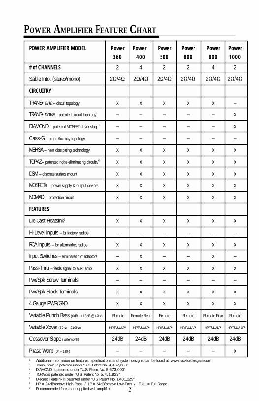
POWER AMPLIFIER MODEL Power Power Power Power Power Power360 400 500 800 800 1000
# of CHANNELS 2 4 2 2 4 2
Stable Into: (stereo/mono) 2Ω/4Ω 2Ω/4Ω 2Ω/4Ω 2Ω/4Ω 2Ω/4Ω 2Ω/4Ω
CIRCUITRY1
TRANS•ana – circuit topology x x x x x –
TRANS•nova – patented circuit topology2 – – – – – x
DIAMOND – patented MOSFET driver stage3 – – – – – x
Class-G – high efficiency topology – – – – – –
MEHSA – heat dissipating technology x x x x x x
TOPAZ – patented noise eliminating circuitry4 x x x x x x
DSM – discrete surface mount x x x x x x
MOSFETs – power supply & output devices x x x x x x
NOMAD – protection circuit x x x x x x
FEATURES
Die Cast Heatsink5 x x x x x x
Hi-Level Inputs – for factory radios – – – – – –
RCA Inputs – for aftermarket radios x x x x x x
Input Switches – eliminates “Y” adaptors – x – – x –
Pass-Thru – feeds signal to aux. amp x x x x x x
Pwr/Spk Screw Terminals – – – – – –
Pwr/Spk Block Terminals x x x x x x
4 Gauge PWR/GND x x x x x x
Variable Punch Bass (0dB ~+18dB @ 45Hz) Remote Remote Rear Remote Remote Remote Rear Remote
Variable Xover (50Hz ~ 210Hz) HP/FULL/LP6 HP/FULL/LP6 HP/FULL/LP6 HP/FULL/LP6 HP/FULL/LP6 HP/FULL/ LP6
Crossover Slope (Butterworth) 24dB 24dB 24dB 24dB 24dB 24dB
Phase Warp (00 ~ 1800) – – – – – x1 Additional information on features, specifications and system designs can be found at: www.rockfordfosgate.com2 Trans•nova is patented under "U.S. Patent No. 4,467,288"3 DIAMOND is patented under "U.S. Patent No. 5,673,000"4 TOPAZ is patented under "U.S. Patent No. 5,751,823"5 Diecast Heatsink is patented under "U.S. Patent No. D401,225"6 HP = 24dB/octave High-Pass / LP = 24dB/octave Low-Pass / FULL = Full Range7 Recommended fuses not supplied with amplifier – 2 –
POWER AMPLIFIER FEATURE CHART
– 3 –
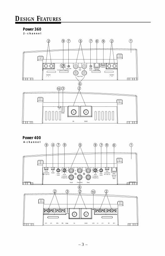
DESIGN FEATURES
Power 3602 - c h a n n e l
Power 4004- c h a n n e l
Speaker+ L -
Crossover FrequencyLeft Gain
Input
Pass-Thru
L R
L R
RightGain
RemotePunch Bass
HP-Full-LPCrossover
Speaker+ R -
6580
55
50
110
210 Hz
145190
REM
B+ GND
LED
5 2987792
6
1
10 3 2
22
6
4 5 7 1
LR+ LR- RR+ RR- B+ GND LF- LF+ RF+RF-REM LED
FrontCrossoverHP-Full-LP
4/2Input
FrontGain Front
CrossoverFrequency
6580
55
50
110
210 Hz
145190
Front Pass-Thru Rear
R R
L L
RearCrossoverFrequency
6580
55
50
110
210 Hz
145190
RearGain
RearCrossoverHP-Full-LP Rear
RemotePunchBass
9 87 9
103 2
9 9

– 4 –
Power 5002 - c h a n n e l
Power 8002 - c h a n n e l
Speaker+ L -
Crossover FrequencyLeft Gain
Input
Pass-Thru
L R
L R
RightGain
RemotePunch Bass
HP-Full-LPCrossover
Speaker+ R -
6580
55
50
110
210 Hz
145190
REM
B+ GND
LED
5 2987792
6
1
10 3 2
10
2 1
23
6
8 99 5 7 27
B+ GND
LED
REM
Speaker+ L -
Crossover FrequencyLeft Gain
Input
Pass-Thru
L R
L R
RightGain
RemotePunch Bass
HP-Full-LPCrossover
Speaker+ R -
6580
55
50
110
210 Hz
145190
– 5 –
Power 8004- c h a n n e l
1
2
6
899 774 5 9 9
3 102 2
LED
LR+ LR- RR+ RR- B+ GND LF- LF+ RF+RF-
REM
FrontCrossoverHP-Full-LP
4/2Input
FrontGain Front
CrossoverFrequency
6580
55
50
110
210 Hz
145190
Front Pass-Thru Rear
R R
L L
RearCrossoverFrequency
6580
55
50
110
210 Hz
145190
RearGain
RearCrossoverHP-Full-LP Rear
RemotePunchBass
Power 10002 - c h a n n e l
2 1
2
8 99 5 7 27
36
10
11
6580
55
50
110
210 Hz
145190
HP–Full–LPCrossoverInput
Pass-Thru
L R
L R
CrossoverFrequency
Speaker+ L -
Speaker+ R -
RightGainLeft
GainRemote
Punch BassPhaseWarp
B+ GND
LED
REM
– 6 –
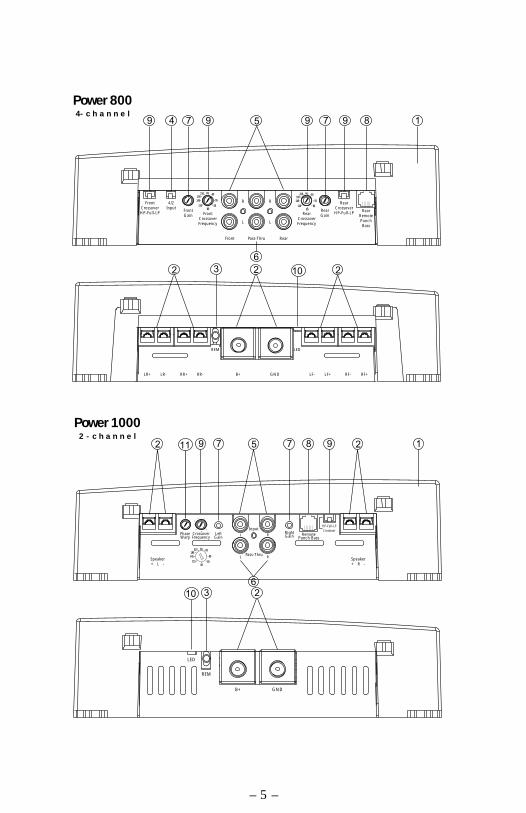
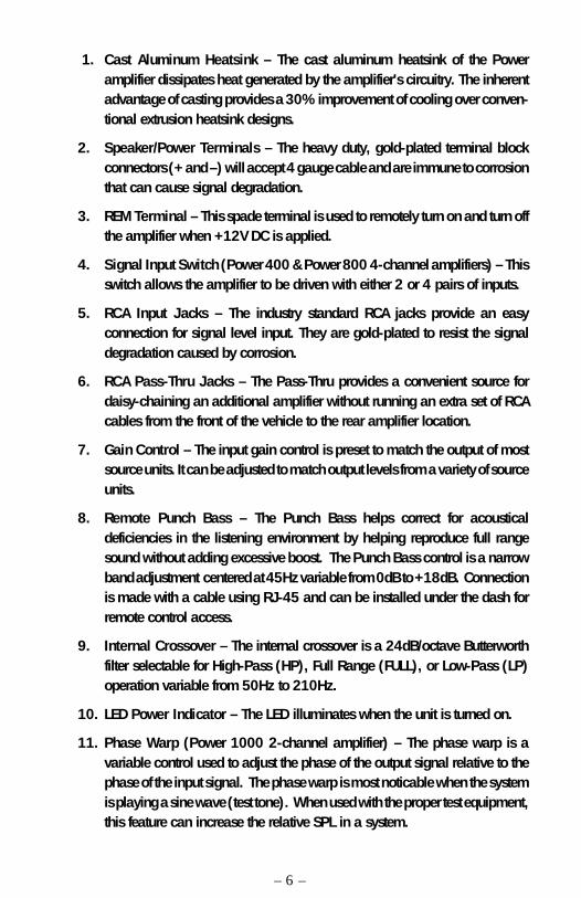
1. Cast Aluminum Heatsink – The cast aluminum heatsink of the Poweramplifier dissipates heat generated by the amplifier's circuitry. The inherentadvantage of casting provides a 30% improvement of cooling over conven-tional extrusion heatsink designs.
2. Speaker/Power Terminals – The heavy duty, gold-plated terminal blockconnectors (+ and –) will accept 4 gauge cable and are immune to corrosionthat can cause signal degradation.
3. REM Terminal – This spade terminal is used to remotely turn on and turn offthe amplifier when +12V DC is applied.
4. Signal Input Switch (Power 400 & Power 800 4-channel amplifiers) – Thisswitch allows the amplifier to be driven with either 2 or 4 pairs of inputs.
5. RCA Input Jacks – The industry standard RCA jacks provide an easyconnection for signal level input. They are gold-plated to resist the signaldegradation caused by corrosion.
6. RCA Pass-Thru Jacks – The Pass-Thru provides a convenient source fordaisy-chaining an additional amplifier without running an extra set of RCAcables from the front of the vehicle to the rear amplifier location.
7. Gain Control – The input gain control is preset to match the output of mostsource units. It can be adjusted to match output levels from a variety of sourceunits.
8. Remote Punch Bass – The Punch Bass helps correct for acousticaldeficiencies in the listening environment by helping reproduce full rangesound without adding excessive boost. The Punch Bass control is a narrowband adjustment centered at 45Hz variable from 0dB to +18dB. Connectionis made with a cable using RJ-45 and can be installed under the dash forremote control access.
9. Internal Crossover – The internal crossover is a 24dB/octave Butterworthfilter selectable for High-Pass (HP), Full Range (FULL), or Low-Pass (LP)operation variable from 50Hz to 210Hz.
10. LED Power Indicator – The LED illuminates when the unit is turned on.
11. Phase Warp (Power 1000 2-channel amplifier) – The phase warp is avariable control used to adjust the phase of the output signal relative to thephase of the input signal. The phase warp is most noticable when the systemis playing a sine wave (test tone). When used with the proper test equipment,this feature can increase the relative SPL in a system.

INSTALLATION CONSIDERATIONS
The following is a list of tools you will need for installing the Power amplifier:Voltmeter Wire strippersElectric hand drill w/assorted bits Battery post wrench17' (5 m) Red Power Wire Wire cutters12' (4 m) Remote Turn-On Wire Assorted connectors1.5' (45 cm) Black Grounding Wire Wire crimpers
– 7 –
This section focuses on some of the vehicle considerations for installing yournew Power amplifier. Checking your battery and present sound system, aswell as pre-planning your system layout and best wiring routes, will saveinstallation time. When deciding how to lay out your new system, be sure thateach component will be easily accessible for making adjustments.
Before beginning any installation, be sure to follow these simple rules:
1. Be sure to carefully read and understand the instructions before attempt-ing to install the amplifier.
2. For safety, disconnect the negative lead from the battery prior tobeginning the installation.
3. For easier assembly, we suggest you run all wires prior to mounting youramplifier in place.
4. Route all of the RCA cables close together and away from any highcurrent wires.
5. Use high quality connectors for a reliable installation and to minimizesignal or power loss.
6. Think before you drill! Be careful not to cut or drill into gas tanks, fuellines, brake or hydraulic lines, vacuum lines or electrical wiring whenworking on any vehicle.
7. Never run wires underneath the vehicle. Running the wires inside thevehicle provides the best protection.
8. Avoid running wires over or through sharp edges. Use rubber or plasticgrommets to protect any wires routed through metal, especially thefirewall.
9. ALWAYS protect the battery and electrical system from damage withproper fusing. Install a fuseholder and appropriate fuse on the +12Vpower wire within 18” (45 cm) of the battery terminal.
10. When grounding to the chassis of the vehicle, scrape all paint from themetal to ensure a good, clean ground connection. Grounding connec-tions should be as short as possible and always be connected to metalthat is welded to the main body, or chassis, of the vehicle.
MOUNTING LOCATION
The mounting location and position of your amplifier will have a great effecton its ability to dissipate the heat generated during normal operation. Thedesign of our cast aluminum heatsink serves to easily dissipate the heatgenerated over a wide range of operating conditions. However, to maximizethe performance of your amplifier, care should be taken to ensure adequateventilation.
Trunk MountingMounting the amplifier vertically on a surface with the fin grooves runningup and down will provide the best cooling of the amplifier.
Mounting the amplifier on the floor of the trunk will work but provides lesscooling capability than vertical mounting.
Mounting the amplifier upside down to the rear deck of the trunk will notprovide proper cooling and will severely affect the performance of theamplifier and is strongly not recommended.
Passenger Compartment MountingMounting the amplifier in the passenger compartment will work as long asyou provide a sufficient amount of air for the amplifier to cool itself. If youare going to mount the amplifier under the seat of the vehicle, you must haveat least 1" (2.54cm) of air gap around the amplifier's heatsink.
Mounting the amplifier with less than 1" (2.54cm) of air gap around theamplifier's heatsink in the passenger compartment will not provide propercooling and will severely affect the performance of the amplifier and isstrongly not recommended.
Engine Compartment MountingRockford Fosgate amplifiers should never be mounted in the enginecompartment. Not only will this void your warranty but could create anembarrassing situation caused by the ridicule from your friends.
– 8 –
BATTERY AND CHARGING
– 9 –
Amplifiers will put an increased load on the vehicle's battery and chargingsystem. We recommend checking your alternator and battery condition toensure that the electrical system has enough capacity to handle theincreased load of your stereo system. Stock electrical systems which are ingood condition should be able to handle the extra load of any Rockfordamplifier without problems, although battery and alternator life can bereduced slightly. To maximize the performance of your Rockford Fosgateamplifier, we suggest the use of a heavy duty battery and an energy storagecapacitor.
WIRING THE SYSTEM
CAUTION: Avoid running power wires near the low level input cables,antenna, power leads, sensitive equipment or harnesses. The power wirescarry substantial current and could induce noise into the audio system.
1. Plan the wire routing. Take care when running signal level RCA cablesto keep them close together but isolated from the amplifier's powercables and any high power auto accessories, especially electricmotors. This is done to prevent coupling the noise from radiatedelectrical fields into the audio signal. When feeding the wires throughthe firewall or any metal barrier, protect them with plastic or rubbergrommets to prevent short circuits. Leave the wires long at this pointto adjust for a precise fit at a later time.
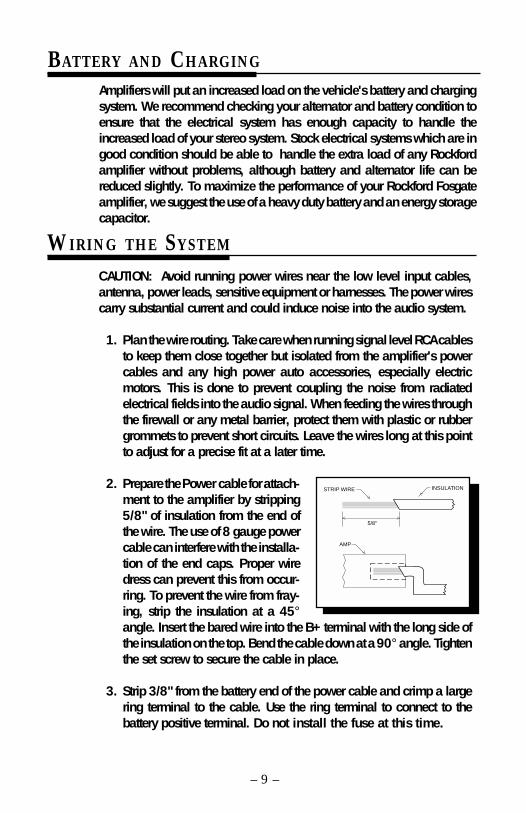
2. Prepare the Power cable for attach-ment to the amplifier by stripping5/8" of insulation from the end ofthe wire. The use of 8 gauge powercable can interfere with the installa-tion of the end caps. Proper wiredress can prevent this from occur-ring. To prevent the wire from fray-ing, strip the insulation at a 45°angle. Insert the bared wire into the B+ terminal with the long side ofthe insulation on the top. Bend the cable down at a 90° angle. Tightenthe set screw to secure the cable in place.
3. Strip 3/8" from the battery end of the power cable and crimp a largering terminal to the cable. Use the ring terminal to connect to thebattery positive terminal. Do not install the fuse at this time.
><5/8"
INSULATIONSTRIP WIRE> >
AMP>
– 10 –
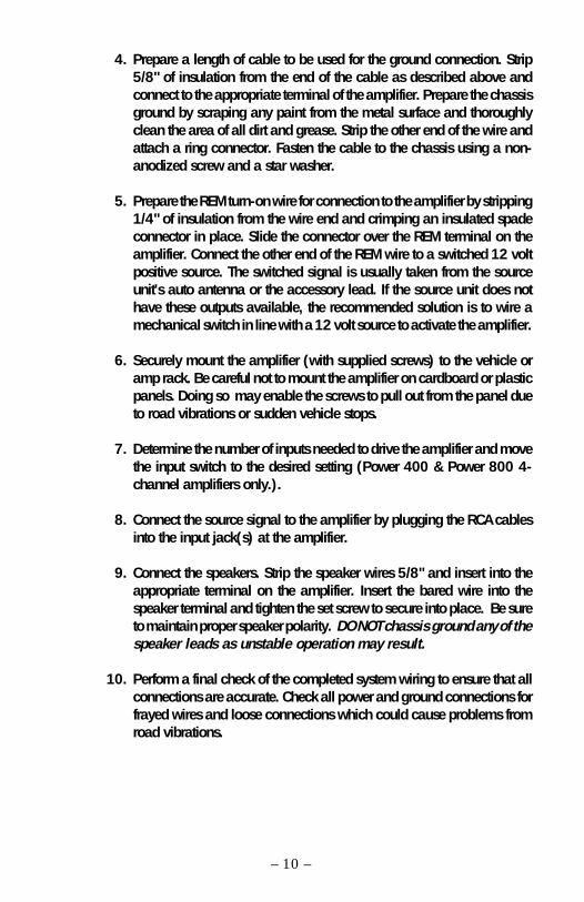
4. Prepare a length of cable to be used for the ground connection. Strip5/8" of insulation from the end of the cable as described above andconnect to the appropriate terminal of the amplifier. Prepare the chassisground by scraping any paint from the metal surface and thoroughlyclean the area of all dirt and grease. Strip the other end of the wire andattach a ring connector. Fasten the cable to the chassis using a non-anodized screw and a star washer.
5. Prepare the REM turn-on wire for connection to the amplifier by stripping1/4" of insulation from the wire end and crimping an insulated spadeconnector in place. Slide the connector over the REM terminal on theamplifier. Connect the other end of the REM wire to a switched 12 voltpositive source. The switched signal is usually taken from the sourceunit's auto antenna or the accessory lead. If the source unit does nothave these outputs available, the recommended solution is to wire amechanical switch in line with a 12 volt source to activate the amplifier.
6. Securely mount the amplifier (with supplied screws) to the vehicle oramp rack. Be careful not to mount the amplifier on cardboard or plasticpanels. Doing so may enable the screws to pull out from the panel dueto road vibrations or sudden vehicle stops.
7. Determine the number of inputs needed to drive the amplifier and movethe input switch to the desired setting (Power 400 & Power 800 4-channel amplifiers only.).
8. Connect the source signal to the amplifier by plugging the RCA cablesinto the input jack(s) at the amplifier.
9. Connect the speakers. Strip the speaker wires 5/8" and insert into theappropriate terminal on the amplifier. Insert the bared wire into thespeaker terminal and tighten the set screw to secure into place. Be sureto maintain proper speaker polarity. DO NOT chassis ground any of thespeaker leads as unstable operation may result.
10. Perform a final check of the completed system wiring to ensure that allconnections are accurate. Check all power and ground connections forfrayed wires and loose connections which could cause problems fromroad vibrations.
– 11 –
USING PASSIVE CROSSOVERS
A passive crossover is a circuit that uses capacitors and/or coils and is placedon speaker leads between the amplifier and speaker. The crossover delegatesa specific range of frequencies to the speaker for optimum driver performance.A crossover network can perform one of three functions: High-Pass (capaci-tors), Low-Pass (inductors or coils) and Bandpass (combination of capacitorand coil).
The most commonly used passive crossover networks are 6dB/octavesystems. These are easy to construct and require one component per filter.Placing this filter in series with the circuit will reduce power to the speaker by6dB/octave above or below the crossover point depending on whether it is ahigh-pass or low-pass filter. More complex systems such as 12dB/octave or18dB/octave can cause impedance problems if not professionally designed.
Passive crossovers are directly dependent upon the speaker's impedance andcomponent value for accuracy. When passive crossover components areused in multiple speaker systems, the crossover's effect on the overallimpedance should be taken into consideration along with the speaker'simpedance when determining amplifier loads. CAUTION: The Power ampli-fiers are not recommended for impedance loads below 2Ω stereo and 4Ωbridged (mono) loads.
advanced
Operation
+
– 12 –
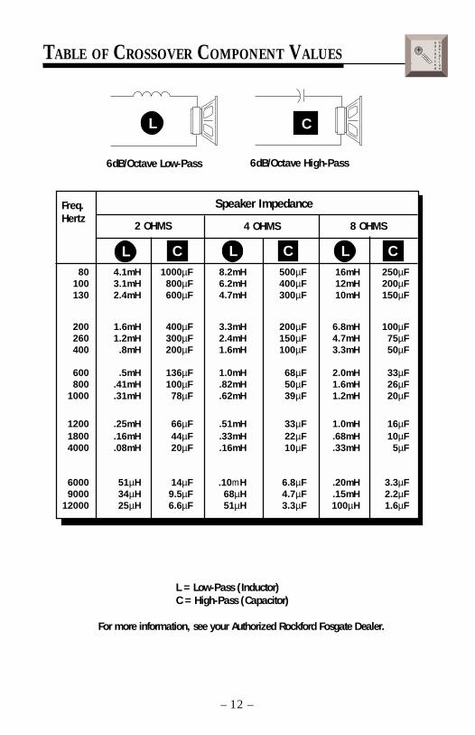
TABLE OF CROSSOVER COMPONENT VALUES
6dB/Octave Low-Pass 6dB/Octave High-Pass
Freq.Hertz
Speaker Impedance
80 4.1mH 1000µF 8.2mH 500µF 16mH 250µF100 3.1mH 800µF 6.2mH 400µF 12mH 200µF130 2.4mH 600µF 4.7mH 300µF 10mH 150µF
200 1.6mH 400µF 3.3mH 200µF 6.8mH 100µF260 1.2mH 300µF 2.4mH 150µF 4.7mH 75µF400 .8mH 200µF 1.6mH 100µF 3.3mH 50µF
600 .5mH 136µF 1.0mH 68µF 2.0mH 33µF800 .41mH 100µF .82mH 50µF 1.6mH 26µF
1000 .31mH 78µF .62mH 39µF 1.2mH 20µF
1200 .25mH 66µF .51mH 33µF 1.0mH 16µF1800 .16mH 44µF .33mH 22µF .68mH 10µF4000 .08mH 20µF .16mH 10µF .33mH 5µF
6000 51µH 14µF .10mH 6.8µF .20mH 3.3µF9000 34µH 9.5µF 68µH 4.7µF .15mH 2.2µF
12000 25µH 6.6µF 51µH 3.3µF 100µH 1.6µF
2 OHMS 8 OHMS4 OHMS
L C L C L C
L C
L = Low-Pass (Inductor)C = High-Pass (Capacitor)
For more information, see your Authorized Rockford Fosgate Dealer.
advanced
Operation
+
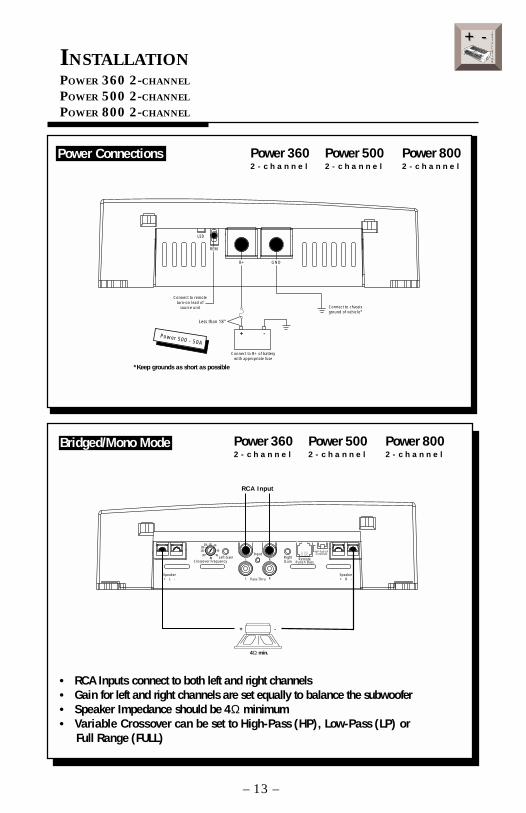
INSTALLATIONPOWER 360 2-CHANNEL
POWER 500 2-CHANNEL
POWER 800 2-CHANNEL
• RCA Inputs connect to both left and right channels• Gain for left and right channels are set equally to balance the subwoofer• Speaker Impedance should be 4Ω minimum• Variable Crossover can be set to High-Pass (HP), Low-Pass (LP) or Full Range (FULL)
INSTALLATION
+ -+ -
– 13 –
Speaker+ L -
Crossover FrequencyLeft Gain
Input
Pass-Thru
L R
L R
RightGain
RemotePunch Bass
HP-Full-LPCrossover
Speaker+ R -
6580
55
50
110
210 Hz
145190
4Ω min.
RCA Input
+ -
Power Connections
Bridged/Mono Mode
Power 360 Power 500 Power 8002 - c h a n n e l 2 - c h a n n e l 2 - c h a n n e l
Power 360 Power 500 Power 8002 - c h a n n e l 2 - c h a n n e l 2 - c h a n n e l
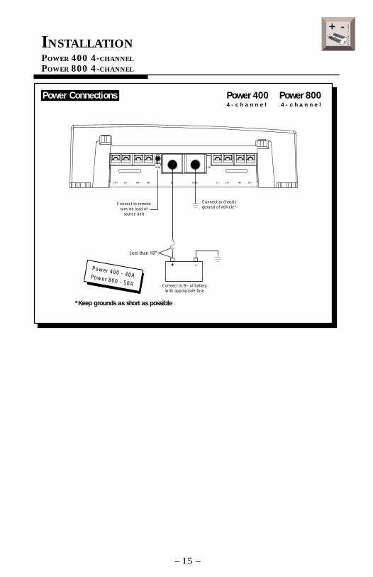
Connect to remoteturn-on lead of
source unit Connect to chassisground of vehicle*
Less than 18"
Connect to B+ of batterywith appropriate fuse
Power 500 - 50A
*Keep grounds as short as possible
+ -
B+ GND
LED
REM
– 14 –
Speaker+ L -
Crossover FrequencyLeft Gain
Input
Pass-Thru
L R
L R
RightGain
RemotePunch Bass
HP-Full-LPCrossover
Speaker+ R -
6580
55
50
110
210 Hz
145190
2Ω min.
RCA Input
2Ω min.
–
+
–
+
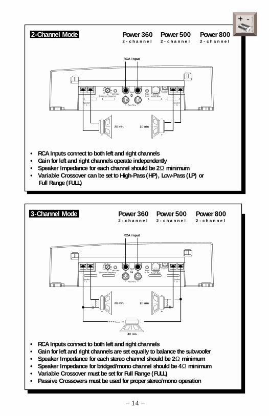
• RCA Inputs connect to both left and right channels• Gain for left and right channels operate independently• Speaker Impedance for each channel should be 2Ω minimum• Variable Crossover can be set to High-Pass (HP), Low-Pass (LP) or Full Range (FULL)
INSTALLATION
+ -+ -
2-Channel Mode Power 360 Power 500 Power 8002 - c h a n n e l 2 - c h a n n e l 2 - c h a n n e l
• RCA Inputs connect to both left and right channels• Gain for left and right channels are set equally to balance the subwoofer• Speaker Impedance for each stereo channel should be 2Ω minimum• Speaker Impedance for bridged/mono channel should be 4Ω minimum• Variable Crossover must be set for Full Range (FULL)• Passive Crossovers must be used for proper stereo/mono operation
Speaker+ L -
Crossover FrequencyLeft Gain
Input
Pass-Thru
L R
L R
RightGain
RemotePunch Bass
HP-Full-LPCrossover
Speaker+ R -
6580
55
50
110
210 Hz
145190
2Ω min.
RCA Input
2Ω min.
–
+
–
+
4Ω min.
+ -
3-Channel Mode Power 360 Power 500 Power 8002 - c h a n n e l 2 - c h a n n e l 2 - c h a n n e l
– 15 –
INSTALLATIONPOWER 400 4-CHANNEL
POWER 800 4-CHANNEL
LED
LR+ LR- RR+ RR- B+ GND LF- LF+ RF+RF-
REM
Connect to remoteturn-on lead of
source unit
Connect to chassisground of vehicle*
Power 400 - 40APower 800 - 50A
*Keep grounds as short as possible
Less than 18"
Connect to B+ of batterywith appropriate fuse
+ -
INSTALLATION
+ -+ -
Power Connections Power 400 Power 8004 - c h a n n e l 4 - c h a n n e l
– 16 –
INSTALLATION
+ -+ -
4-2Input
LED
LR+ LR- RR+ RR- B+ GND LF- LF+ RF+RF-
REM
FrontCrossoverHP-Full-LP
4/2Input
FrontGain Front
CrossoverFrequency
6580
55
50
110
210 Hz
145190
Front Pass-Thru Rear
R R
L L
RearCrossoverFrequency
6580
55
50
110
210 Hz
145190
RearGain
RearCrossoverHP-Full-LP Rear
RemotePunchBass
RCA Input
4Ω min.Bridged
Left
+ -
4Ω min.BridgedRight
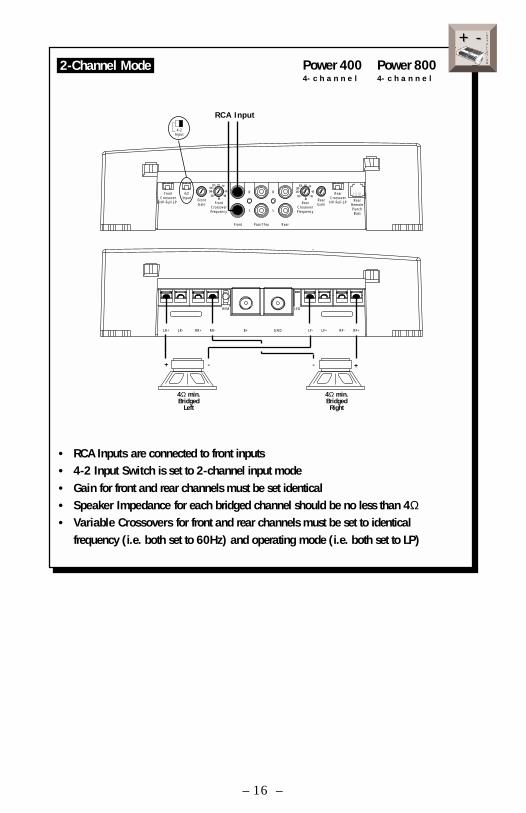
+ -• RCA Inputs are connected to front inputs• 4-2 Input Switch is set to 2-channel input mode• Gain for front and rear channels must be set identical• Speaker Impedance for each bridged channel should be no less than 4Ω• Variable Crossovers for front and rear channels must be set to identical
frequency (i.e. both set to 60Hz) and operating mode (i.e. both set to LP)
2-Channel Mode Power 400 Power 8004- c h a n n e l 4- c h a n n e l
– 17 –
INSTALLATION
+ -+ -
4-2Input
4-2Input
LED
LR+ LR- RR+ RR- B+ GND LF- LF+ RF+RF-
REM
FrontCrossoverHP-Full-LP
4/2Input
FrontGain Front
CrossoverFrequency
6580
55
50
110
210 Hz
145190
Front Pass-Thru Rear
R R
L L
RearCrossoverFrequency
6580
55
50
110
210 Hz
145190
RearGain
RearCrossoverHP-Full-LP Rear
RemotePunchBass
*
-or-
2-channelInput
4Ω min.Bridged
+ -
2Ω min.
+ -
2Ω min.
+ -
4-channelInput
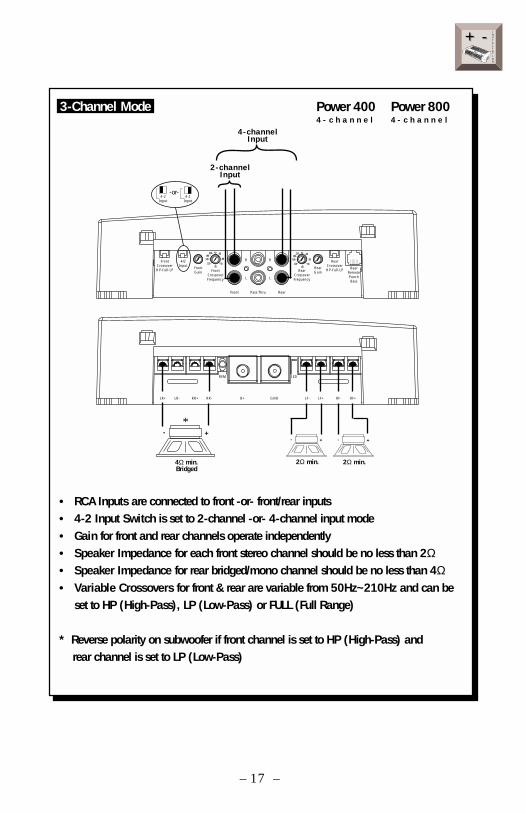
• RCA Inputs are connected to front -or- front/rear inputs• 4-2 Input Switch is set to 2-channel -or- 4-channel input mode• Gain for front and rear channels operate independently• Speaker Impedance for each front stereo channel should be no less than 2Ω• Speaker Impedance for rear bridged/mono channel should be no less than 4Ω• Variable Crossovers for front & rear are variable from 50Hz~210Hz and can be
set to HP (High-Pass), LP (Low-Pass) or FULL (Full Range)
* Reverse polarity on subwoofer if front channel is set to HP (High-Pass) and rear channel is set to LP (Low-Pass)
3-Channel Mode Power 400 Power 8004 - c h a n n e l 4 - c h a n n e l
– 18 –
INSTALLATION
+ -+ -
4-2Input
FrontCrossoverHP-Full-LP
4/2Input
FrontGain Front
CrossoverFrequency
6580
55
50
110
210 Hz
145190
Front Pass-Thru Rear
R R
L L
RearCrossoverFrequency
6580
55
50
110
210 Hz
145190
RearGain
RearCrossoverHP-Full-LP Rear
RemotePunchBass
LED
LR+ LR- RR+ RR- B+ GND LF- LF+ RF+RF-
REM
2Ω min.
+ -
2Ω min.
+ -
4-channelInput
+ - + -
2Ω min.2Ω min.
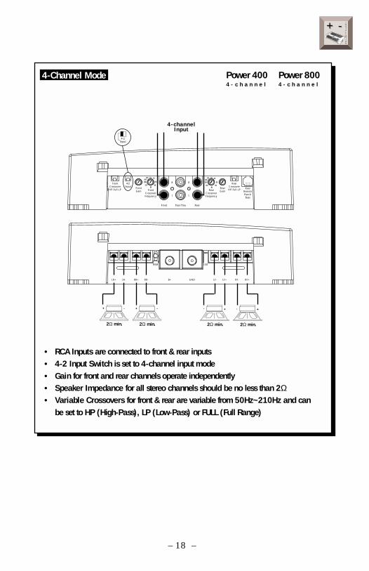
• RCA Inputs are connected to front & rear inputs• 4-2 Input Switch is set to 4-channel input mode• Gain for front and rear channels operate independently• Speaker Impedance for all stereo channels should be no less than 2Ω• Variable Crossovers for front & rear are variable from 50Hz~210Hz and can
be set to HP (High-Pass), LP (Low-Pass) or FULL (Full Range)
4-Channel Mode Power 400 Power 8004 - c h a n n e l 4 - c h a n n e l
– 19 –
INSTALLATION
+ -+ -
INSTALLATIONPOWER 1000 2-CHANNEL
Connect to remoteturn-on lead of
source unit
Less than 18"
Connect to B+ of batterywith appropriate fuse
(1) 100A ANLPower 1000 - -or- (2) 50A AGU
*Keep grounds as short as possible
Connect to chassisground of vehicle*
+ -
B+ GND
LED
REM
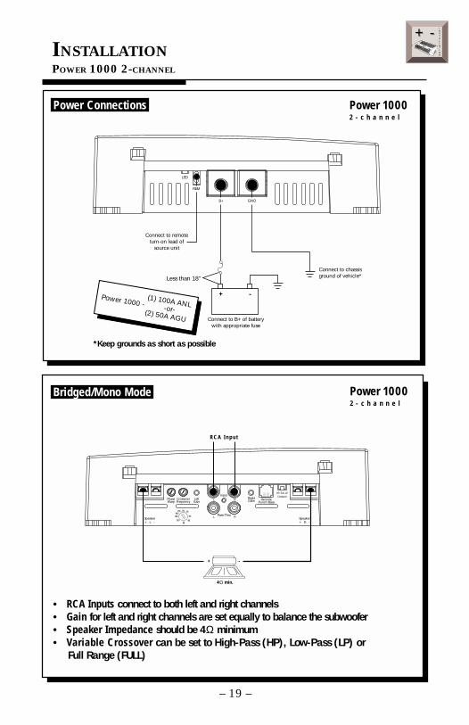
• RCA Inputs connect to both left and right channels• Gain for left and right channels are set equally to balance the subwoofer• Speaker Impedance should be 4Ω minimum• Variable Crossover can be set to High-Pass (HP), Low-Pass (LP) or Full Range (FULL)
6580
55
50
110
210 Hz
145190
HP–Full–LPCrossoverInput
Pass-Thru
L R
L R
CrossoverFrequency
Speaker+ L -
Speaker+ R -
RightGainLeft
GainRemote
Punch BassPhaseWarp
4Ω min.
RCA Input
+ -
Power Connections
Bridged/Mono Mode
Power 10002 - c h a n n e l
Power 10002 - c h a n n e l
– 20 –
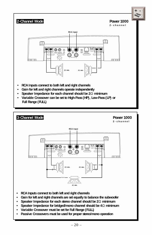
• RCA Inputs connect to both left and right channels• Gain for left and right channels operate independently• Speaker Impedance for each channel should be 2Ω minimum• Variable Crossover can be set to High-Pass (HP), Low-Pass (LP) or Full Range (FULL)
6580
55
50
110
210 Hz
145190
HP–Full–LPCrossoverInput
Pass-Thru
L R
L R
CrossoverFrequency
Speaker+ L -
Speaker+ R -
RightGainLeft
GainRemote
Punch BassPhaseWarp
RCA Input
2Ω min. 2Ω min.
–
+
–
+
• RCA Inputs connect to both left and right channels• Gain for left and right channels are set equally to balance the subwoofer• Speaker Impedance for each stereo channel should be 2Ω minimum• Speaker Impedance for bridged/mono channel should be 4Ω minimum• Variable Crossover must be set for Full Range (FULL)• Passive Crossovers must be used for proper stereo/mono operation
6580
55
50
110
210 Hz
145190
HP–Full–LPCrossoverInput
Pass-Thru
L R
L R
CrossoverFrequency
Speaker+ L -
Speaker+ R -
RightGainLeft
GainRemote
Punch BassPhaseWarp
RCA Input
2Ω min. 2Ω min.
–
+
–
+
4Ω min.
+ -
INSTALLATION
+ -+ -
2-Channel Mode
3-Channel Mode
Power 10002 - c h a n n e l
Power 10002 - c h a n n e l
– 21 –
INSTALLATION
+ -+ -
OPERATION
Crossover Operation
+3
+2
+1
0
–1
–2
–3
–4
–5
–6
–7
–8
–9
–10
–11
–12
Ap
50 80 210 500 1k 2k55 65 110145
Ap+3
+2
+1
0
–1
–2
–3
–4
–5
–6
–7
–8
–9
–10
–11
–1250 80 210 500 1k 2k55 65 110145
Speaker+ L -
Crossover FrequencyLeft Gain
Input
Pass-Thru
L R
L R
RightGain
RemotePunch Bass
HP-Full-LPCrossover
Speaker+ R -
6580
55
50
110
210 Hz
145190
Frequency in Hz
6580
55
50
110
210 Hz
145
190
Low-Pass (LP)
Operation
Crossover FrequencyCrossover
HP – Full – LP
Frequency in Hz
6580
55
50
110
210 Hz
145
190
High-Pass (HP)
Operation
Crossover FrequencyCrossover
HP – Full – LP
1 2 1 2
1 2
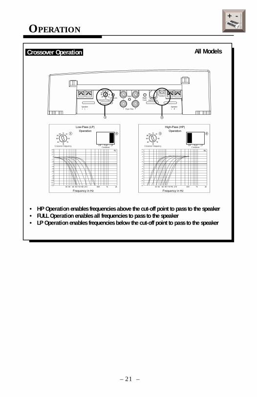
• HP Operation enables frequencies above the cut-off point to pass to the speaker• FULL Operation enables all frequencies to pass to the speaker• LP Operation enables frequencies below the cut-off point to pass to the speaker
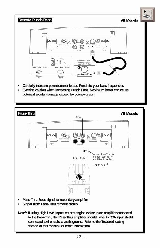
All Models
– 22 –
• Carefully increase potentiometer to add Punch to your bass frequencies• Exercise caution when increasing Punch Bass. Maximum boost can cause
potential woofer damage caused by overexcursion
Speaker+ L -
Crossover FrequencyLeft Gain
Input
Pass-Thru
L R
L R
RightGain
RemotePunch Bass
HP-Full-LPCrossover
Speaker+ R -
6580
55
50
110
210 Hz
145190
MinimumFlat
MaximumBoost
-0 +18
BASS-0 +18-0 +18
33Hz 45Hz 67.5Hz
+18+12+6+3
0dB
33Hz 45Hz 67.5Hz
Install Punch Bass in aconvenient locationunder vehicle’s dash
• Pass-Thru feeds signal to secondary amplifier• Signal from Pass-Thru remains stereo
Note1: If using High Level Inputs causes engine whine in an amplifier connected to the Pass-Thru, the Pass-Thru amplifier should have its RCA input shield connected to the radio chassis ground. Refer to the Troubleshooting section of this manual for more information.
Speaker+ L -
Crossover FrequencyLeft Gain
Input
Pass-Thru
L R
L R
RightGain
RemotePunch Bass
HP-Full-LPCrossover
Speaker+ R -
6580
55
50
110
210 Hz
145190
Input
Connect Pass-Thru toinput of secondaryamplifier if needed.Left Right
See Note1
Remote Punch Bass
Pass-Thru
All Models
INSTALLATION
+ -+ -
All Models
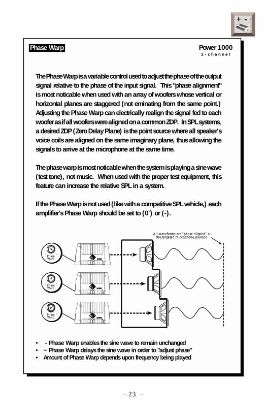
The Phase Warp is a variable control used to adjust the phase of the outputsignal relative to the phase of the input signal. This "phase alignment"is most noticable when used with an array of woofers whose vertical orhorizontal planes are staggered (not eminating from the same point.)Adjusting the Phase Warp can electrically realign the signal fed to eachwoofer as if all woofers were aligned on a common ZDP. In SPL systems,a desired ZDP (Zero Delay Plane) is the point source where all speaker'svoice coils are aligned on the same imaginary plane, thus allowing thesignals to arrive at the microphone at the same time.
The phase warp is most noticable when the system is playing a sine wave(test tone), not music. When used with the proper test equipment, thisfeature can increase the relative SPL in a system.
If the Phase Warp is not used (like with a competitive SPL vehicle,) eachamplifier's Phase Warp should be set to (0˚) or (-).
INSTALLATION
+ -+ -
– 23 –
Phase Warp
- ~PhaseWarp
- ~PhaseWarp
- ~PhaseWarp
All waveforms are ”phase aligned” atthe targeted microphone position
• - Phase Warp enables the sine wave to remain unchanged• ~ Phase Warp delays the sine wave in order to "adjust phase"• Amount of Phase Warp depends upon frequency being played
Power 1000 2 - c h a n n e l
– 24 –
SYSTEM DIAGRAMS
FanaticComponent
System
Power4-ChannelAmplifier
Punch Woofers
Front Rear
24dB/octave LP20Hz - 80Hz
fnx1414
24dB/octave HP80Hz - 20kHz
+
–
+
–
+
– +
–+
–
+
–
8Ω
+ –
+ –
fnx1414
8Ω
BAND
DISP AS/PS
LOUDMODE
MUTE
TUNE1 2 3 4 5 6
SELVOL
COMPACT DISC PLAYER WITH DIGITAL TUNER
RPTTRACK SCAN RDM DISC
PUSH
SEEKMENU
ST RPT RDMLOUDLOCAL
CD CHANGER CONTROL
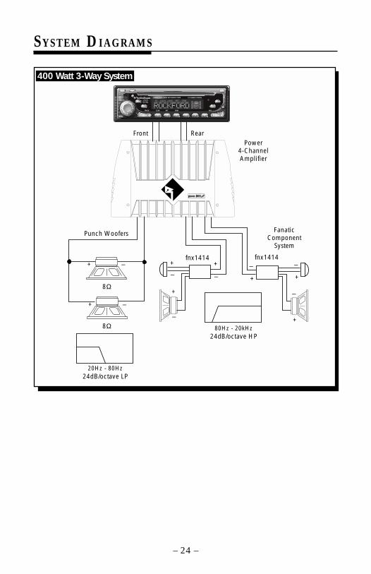
400 Watt 3-Way System
– 25 –
Front Rear
12dB/octave LP12dB/octave HP
80Hz - 275Hz
24dB/octave HP275Hz - 20kHz
fnx1414+
–
+
–
+
– +
–+
–
+
–
+
–
+
–
+
–
+
–
24dB/octave LP20Hz - 80Hz
8Ω 8Ω
4Ω 4Ω
fnx1414
Power4-ChannelAmplifier
Punch Woofers
Power2-ChannelAmplifier
PunchMidbass
FanaticComponent
System
Pass-Thru
BAND
DISP AS/PS
LOUDMODE
MUTE
TUNE1 2 3 4 5 6
SELVOL
COMPACT DISC PLAYER WITH DIGITAL TUNER
RPTTRACK SCAN RDM DISC
PUSH
SEEKMENU
ST RPT RDMLOUDLOCAL
CD CHANGER CONTROL
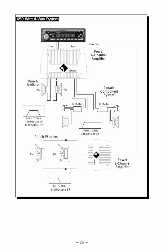
650 Watt 4-Way System
– 26 –
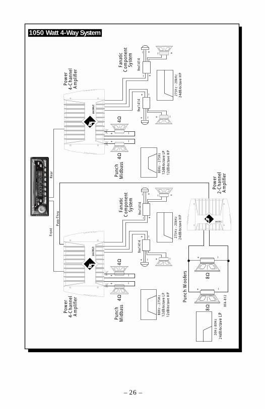
Fron
t
12dB
/oct
ave
LP12
dB/o
ctav
e H
P
80H
z -
275H
z
fnx1
414
24dB
/oct
ave
HP
275H
z -
20kH
z
fnx1
414
+ – + –
+ –
+–+– +–
+ –
+ –
+ –
+ –24
dB/o
ctav
e LP
20H
z-80
Hz
RFA
-812
12dB
/oct
ave
LP12
dB/o
ctav
e H
P
80H
z -
275H
z
fnx1
414
24dB
/oct
ave
HP
275H
z -
20kH
z
fnx1
414
+ – + –
+ –
+–+– +–
+ –
+ –
Rea
r
Pass
-Thr
u
Pow
er4-
Cha
nnel
Am
plifi
er
Pow
er4-
Cha
nnel
Am
plifi
er
Punc
hM
idba
ss 8Ω
4Ω4Ω
4Ω
8ΩPo
wer
2-C
hann
elA
mpl
ifier
4ΩFa
natic
Com
pone
ntSy
stem
Fana
ticC
ompo
nent
Syst
em
Punc
hM
idba
ss
Punc
h W
oofe
rs
BAND
DISP
AS/ P
S
LOUD
MOD
E
MUT
E
TUNE
12
34
56
SEL
VOL
COM
PACT
DIS
C PL
AYER
WIT
H DI
GITA
L TU
NER
RPT
TRAC
KSC
ANRD
MDI
SC
PUSH
SEEK
MEN
U
ST
RP
TR
DM
LOU
DLO
CA
L
CD C
HANG
ER C
ONTR
OL
1050 Watt 4-Way System
– 27 –
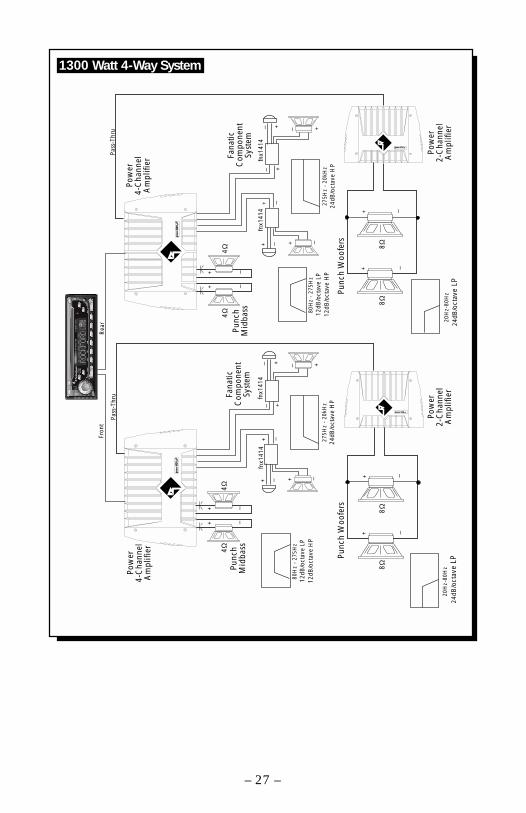
Fron
t
12dB
/oct
ave
LP12
dB/o
ctav
e H
P
80H
z -
275H
z
24dB
/oct
ave
HP
275H
z -
20kH
z
+ – + –
+ –
+–+– +–
+ –
+ –
+ –
+ –
24dB
/oct
ave
LP20
Hz-
80H
z
12dB
/oct
ave
LP12
dB/o
ctav
e H
P
80H
z -
275H
z
24dB
/oct
ave
HP
275H
z -
20kH
z
+ – + –
+ –
+–+– +–
+ –
+ –
Rea
r
Pass
-Thr
u
+ –
+ –
20H
z-80
Hz
Pass
-Thr
u
24dB
/oct
ave
LP
fnx1
414
fnx1
414
fnx1
414
fnx1
414
Pow
er4-
Cha
nnel
Am
plifi
er
Pow
er4-
Cha
nnel
Am
plifi
er
Punc
hM
idba
ss
8Ω
Pow
er2-
Cha
nnel
Am
plifi
er
4ΩFa
natic
Com
pone
ntSy
stem
Fana
ticC
ompo
nent
Syst
emPu
nch
Mid
bass
Punc
h W
oofe
rs
4Ω4Ω
4Ω
8Ω
Pow
er2-
Cha
nnel
Am
plifi
er
8Ω8Ω
Punc
h W
oofe
rs
BAND
DISP
AS/ P
S
LOUD
MOD
E
MUT
E
TUNE
12
34
56
SEL
VOL
COM
PACT
DIS
C PL
AYER
WIT
H DI
GITA
L TU
NER
RPT
TRAC
KSC
ANRD
MDI
SC
PUSH
SEEK
MEN
U
ST
RP
TR
DM
LOU
DLO
CA
L
CD C
HANG
ER C
ONTR
OL
1300 Watt 4-Way System
– 28 –
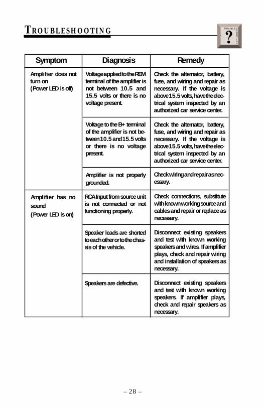
TROUBLESHOOTING
Amplifier does notturn on(Power LED is off)
Symptom Diagnosis Remedy
Voltage applied to the REMterminal of the amplifier isnot between 10.5 and15.5 volts or there is novoltage present.
Voltage to the B+ terminalof the amplifier is not be-tween 10.5 and 15.5 voltsor there is no voltagepresent.
Amplifier is not properlygrounded.
Amplifier has nosound(Power LED is on)
RCA Input from source unitis not connected or notfunctioning properly.
Speaker leads are shortedto each other or to the chas-sis of the vehicle.
Speakers are defective.
Check connections, substitutewith known working source andcables and repair or replace asnecessary.
Disconnect existing speakersand test with known workingspeakers and wires. If amplifierplays, check and repair wiringand installation of speakers asnecessary.
Disconnect existing speakersand test with known workingspeakers. If amplifier plays,check and repair speakers asnecessary.
Check the alternator, battery,fuse, and wiring and repair asnecessary. If the voltage isabove 15.5 volts, have the elec-trical system inspected by anauthorized car service center.
Check the alternator, battery,fuse, and wiring and repair asnecessary. If the voltage isabove 15.5 volts, have the elec-trical system inspected by anauthorized car service center.
Check wiring and repair as nec-essary.
TROUBLE-SHOOTING?
– 29 –
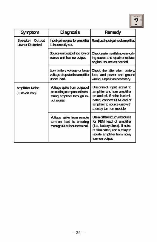
Speaker OutputLow or Distorted
Readjust input gains of amplifier.
Check system with known work-ing source and repair or replaceoriginal source as needed.
Check the alternator, battery,fuse, and power and groundwiring. Repair as necessary.
Symptom Diagnosis Remedy
Input gain signal for amplifieris incorrectly set.
Source unit output too low orsource unit has no output.
Low battery voltage or largevoltage drops to the amplifierunder load.
Amplifier Noise(Turn-on Pop)
Voltage spike from output ofpreceding component is en-tering amplifier through in-put signal.
Voltage spike from remoteturn-on lead is enteringthrough REM input terminal.
Disconnect input signal toamplifier and turn amplifieron and off. If noise is elimi-nated, connect REM lead ofamplifier to source unit witha delay turn-on module.
Use a different 12 volt sourcefor REM lead of amplifier(i.e., battery direct). If noiseis eliminated, use a relay toisolate amplifier from noisyturn-on output.
TROUBLE-SHOOTING?
– 30 –
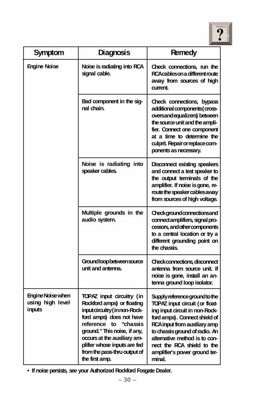
Noise is radiating into RCAsignal cable.
Bad component in the sig-nal chain.
Noise is radiating intospeaker cables.
Multiple grounds in theaudio system.
Ground loop between sourceunit and antenna.
TOPAZ input circuitry (inRockford amps) or floatinginput circuitry (in non-Rock-ford amps) does not havereference to “chassisground.” This noise, if any,occurs at the auxiliary am-plifier whose inputs are fedfrom the pass-thru output ofthe first amp.
Engine Noise
Symptom Diagnosis Remedy
Check connections, run theRCA cables on a different routeaway from sources of highcurrent.
Check connections, bypassadditional components (cross-overs and equalizers) betweenthe source unit and the ampli-fier. Connect one componentat a time to determine theculprit. Repair or replace com-ponents as necessary.
Disconnect existing speakersand connect a test speaker tothe output terminals of theamplifier. If noise is gone, re-route the speaker cables awayfrom sources of high voltage.
Check ground connections andconnect amplifiers, signal pro-cessors, and other componentsto a central location or try adifferent grounding point onthe chassis.
Check connections, disconnectantenna from source unit. Ifnoise is gone, install an an-tenna ground loop isolator.
Supply reference ground to theTOPAZ input circuit (or float-ing input circuit in non-Rock-ford amps). Connect shield ofRCA input from auxiliary ampto chassis ground of radio. Analternative method is to con-nect the RCA shield to theamplifier's power ground ter-minal.
• If noise persists, see your Authorized Rockford Fosgate Dealer.
TROUBLE-SHOOTING?
Engine Noise whenusing high levelinputs
– 31 –
DYNAMIC POWER MEASUREMENTS
About the Dynamic Power MeasurementsThe Audio Graph PowerCube is a test instrument used to measure the output ofan amplifier in accordance with IHF-202 industry standards. The IHF-202standard is a dynamic power measurement and was developed as a means ofmeasuring power in a manner that best represents the Real World operation of anamplifier. Many manufacturers, including Rockford Fosgate, at times will measureamplifier power into a fixed resistor (4 ohm, 2 ohm). While this method is usefulin some types of evaluation and testing, it is not representative of an amplifier thatis connected to a speaker and playing music.
MusicMusic is dynamic; the sound waves are complex and constantly changing. Inorder to simulate this, the IHF-202 standard calls for the input signal to theamplifier to be a 1kHz bursted tone. This signal is input (on for 20 milliseconds)and reduced 20dB for 480 milliseconds. The signal is gradually increased in leveluntil the amplifier's output exceeds 1% Total Harmonic Distortion (THD). At 1%distortion becomes audible, therefore, any power produced above that level isconsidered unusable. Many manufacturers represent their amplifiers' outputpower in excess of 10% distortion. They use many names for this measurement,such as Total Maximum Power or Maximum Output Power. This is not indicativeof the actual usable output power.
Listening to Loudspeakers - Not ResistorsA loudspeaker is not a resistor. A resistor's value (resistance measured in ohms)is fixed. A loudspeaker's impedance is dynamic. It is constantly changing in value,dependent upon the frequency of the input signal. Therefore, measuring powerwith the amplifier loaded into a 4 ohm resistor is not the same as measuring powerwith the amplifier connected to a 4 ohm speaker. Most people do not listen tomusic through a resistor.A 4 ohm speaker may experience a drop in impedance 4-6 times lower than itsnominal (printed) impedance. A speaker will also create phase shifts in the signalthat is passed through it. These phase shifts happen because a speaker is aninductor (voice coil) and a capacitor (compliance of the surround/spider), as wellas a resistor (voice coil wire).To simulate a speaker the Audio Graph PowerCube measures output power into20 different loads. It tests at 8 ohms, 4 ohms, 2 ohms and 1 ohm. Each of theseimpedances is also tested at –60°, –30°, 0°, +30° and +60° phase angles.These different impedances and phase angles represent the shifts in impedanceand phase that can occur in a typical loudspeaker.
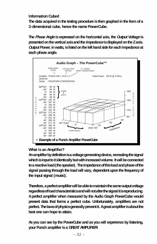
Information CubedThe data acquired in the testing procedure is then graphed in the form of a3-dimensional cube, hence the name PowerCube.
The Phase Angle is expressed on the horizontal axis, the Output Voltage ispresented on the vertical axis and the Impedance is displayed on the Z axis.Output Power, in watts, is listed on the left hand side for each impedance ateach phase angle.
What is an Amplifier?An amplifier by definition is a voltage generating device, recreating the signalwhich is input to it identically but with increased volume. It will be connectedto a reactive load (the speaker). The impedance of this load and phase of thesignal passing through the load will vary, dependent upon the frequency ofthe input signal (music).
Therefore, a perfect amplifier will be able to maintain the same output voltageregardless of load characteristics and will not alter the signal it is reproducing.A perfect amplifier when measured by the Audio Graph PowerCube wouldpresent data that forms a perfect cube. Unfortunately, amplifiers are notperfect. The laws of physics generally prevent it. A great amplifier is about thebest one can hope to attain.
As you can see by the PowerCube and as you will experience by listening,your Punch amplifier is a GREAT AMPLIFIER!
– 32 –
–60° (Cap)0°
(Ind) +60°1Ω
2Ω4Ω
Impedance
8Ω
10V
30V
50V
8Ω –60°–30°
0°30°60°
4Ω –60°–30°
0°30°60°
2Ω –60°–30°
0°30°60°
1Ω –60°–30°
0°30°60°
85 W84 W84 W84 W86 W
162 W157 W156 W157 W162 W273 W258 W251 W256 W271 W390 W356 W346 W352 W390 W
Audio Graph – The PowerCube™
Amplifier:Serial No:Owner :
PUNCH 200.2 14.4V x 2
ROCKFORD CORPORATION
Rated Power : 100 W @ 4 Ohms
IM
PE
DA
NC
E
MODEL BEINGTESTED
x2 = STEREOMONO = BRIDGED MONO
VOLTAGE FROMBATTERY
OU
TP
UT
V
OL
TA
GE
*
*
*
*
PHASE ANGLES
POWERIN
WATTS
• Example of a Punch Amplifier PowerCube
LIMITED WARRANTY INFORMATION
– 33 –
Ship to: SpeakersRockford Acoustic Design(Receiving-speakers)609 Myrtle N.W.Grand Rapids, MI 49504RA#:_________________
Ship to: ElectronicsRockford CorporationWarranty Repair Department2055 E. 5th StreetTempe, AZ 85281RA#:_________________
Rockford Corporation offers a limited warranty on Rockford Fosgate products on the followingterms:
• Length of Warranty3 years on electronics 90 days on electronic B-stock (receipt required)2 years on source units 90 days on speaker B-stock (receipt required)1 year on speakers
• What is CoveredThis warranty applies only to Rockford Fosgate products sold to consumers by AuthorizedRockford Fosgate Dealers in the United States of America or its possessions. Productpurchased by consumers from an Authorized Rockford Fosgate Dealer in another countryare covered only by that country’s Distributor and not by Rockford Corporation.
• Who is CoveredThis warranty covers only the original purchaser of Rockford product purchased from anAuthorized Rockford Fosgate Dealer in the United States. In order to receive service, thepurchaser must provide Rockford with a copy of the receipt stating the customer name,dealer name, product purchased and date of purchase.
• Products found to be defective during the warranty period will be repaired or replaced(with a product deemed to be equivalent) at Rockford's discretion.
• What is Not Covered1. Damage caused by accident, abuse, improper operations, water, theft2. Any cost or expense related to the removal or reinstallation of product3. Service performed by anyone other than Rockford or an Authorized Rockford Fosgate
Service Center4. Any product which has had the serial number defaced, altered, or removed5. Subsequent damage to other components6. Any product purchased outside the U.S.7. Any product not purchased from an Authorized Rockford Fosgate Dealer
• Limit on Implied WarrantiesAny implied warranties including warranties of fitness for use and merchantability arelimited in duration to the period of the express warranty set forth above. Some states do notallow limitations on the length of an implied warranty, so this limitation may not apply. Noperson is authorized to assume for Rockford Fosgate any other liability in connection withthe sale of the product.
• How to Obtain ServicePlease call 1-800-669-9899 for Rockford Customer Service. You must obtain an RA#(Return Authorization number) to return any product to Rockford Fosgate. You areresponsible for shipment of product to Rockford.

I NT E R N A T I O
N A L I N F O R MA T I O N
– 34 –
LEA DETENIDAMENTE LAS SIGUIENTES INSTRUCCIONES DE INSTALACION DELPRODUCTO. EVITARA POSIBLES DAÑOS A VD., AL VEHICULO O AL PRODUCTO.
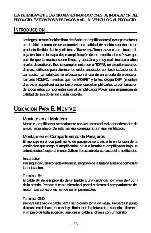
Montaje en el MalateroMonte el amplificador verticalmente con las lineas del radiador orientadas dearriba hacia abajo. De esta manera conseguira la mejor ventilacion.
Montaje en el Compartimento de PasajerosEl montaje en el compartimento de pasajeros sera eficiente en funcion de laventilacion que tenga el amplificador. Si va a instalar el amplificador bajo unasiento deberá dejar al menos 2.5cm libres sobre la carcasa del amplificador.
InstalacionPor seguridad, desconecte el terminal negativo de la bateria antes de comenzarla instalacion.
Terminal B+El cable B+ debe ir provisto de un fusible a una distancia no mayor de 45cmde la bateria. Prepare el cable e instale el portafusibles en el compartimento delmotor. Las conexiones han de ser impermeables.
Terminal GNDPrepare un trozo de cable para usarlo como toma de masa. Prepare un puntode masa en el chasis rascando y eliminando la pintura de la superficie de metaly limpielo de toda suciedad asegure el cable al chasis con un tornillo.
UBICACIÓN PARA EL MONTAJE
– 35 –
Los ingenieros de Rockford han diseñado los amplificadores Power para ofreceren el dificil entorno de un automóvil una calidad de sonido superior en unproducto flexible, fiable y eficiente. Trans•ana/Trans•nova es un circuito debaja tensión en la etapa de preamplificación de los amplificadores Power quepermite que la musica suene limpia y cristalina y muy real, incluso a altosniveles de audicion. Esto se complementa con el TOPAZ, un circuito exclusivode masa utilizado para eliminar los ruidos asociados con las instalaciones decar-audio. La fiabilidad se refuerza con el uso de un circuito de proteccionllamado NOMAD, mientras que los MOSFET y la tecnologia DSM (montajediscreto en superficie) aumentan la eficiencia del amplificador. La combinacionde todos estos componentes dan al amplificador Power una impresionantecalidad de sonido en un chasis discreto.
INTRODUCCION

– 36 –
Terminal REMConecte el cable REM a un punto de +12V con mutable. La señal se suele coger dela salida auto antena del radio cassette si este no tiene salida remote.
Speaker+ L -
Crossover FrequencyLeft Gain
Input
Pass-Thru
L R
L R
RightGain
RemotePunch Bass
HP-Full-LPCrossover
Speaker+ R -
6580
55
50
110
210 Hz
145190
2Ω min.
Ent radas2-canales
2Ω min.
–
+
–
+
4Ω min.
+ -
ESPAÑ
OL
Funcionamiento Estereo/Mono Power 360 Power 5002 - c a n a l e s 2 - c a n a l e s
Power 800 Power 10002 - c a n a l e s 2 - c a n a l e s
4-2Entradas
LED
LR+ LR- RR+ RR- B+ GND LF- LF+ RF+RF-
REM
FrontCrossoverHP-Full-LP
4/2Input
FrontGain Front
CrossoverFrequency
6580
55
50
110
210 Hz
145190
Front Pass-Thru Rear
R R
L L
RearCrossoverFrequency
6580
55
50
110
210 Hz
145190
RearGain
RearCrossoverHP-Full-LP Rear
RemotePunchBass
2Ω min.
+ -
2Ω min.
+ -
Ent radas4-canales
+ - + -
2Ω min.2Ω min.
– 37 –
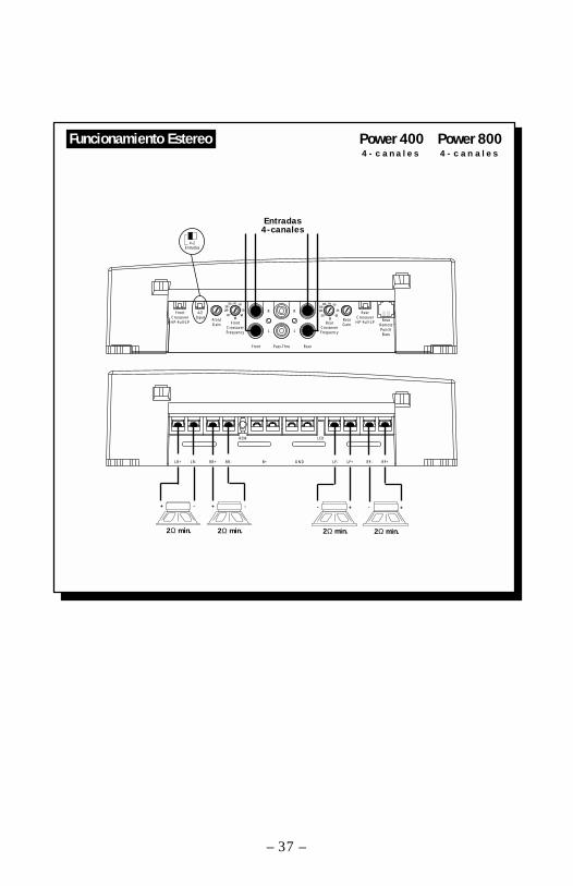
Funcionamiento Estereo Power 400 Power 800 4 - c a n a l e s 4 - c a n a l e s

ATTENTION: Veuillez lire les instructions suivantes pour l'installation de cetamplificateur. Ne pas les suivre pourrait causer des blessures ou endommagerle véhicule.
Les ingénieurs de Rockford Fosgate ont conçu l'amplificateur Power poursupporter l'environnement rude de l'automobile en délivrant une qualité de sonsupérieure dans un ensemble efficace, fiable et flexible. Trans•ana/Trans•novaest un circuit de bas voltage dans l'étage de préamplification de tous lesamplificateurs Punch qui reproduit un son musical clair comme du cristal et trèsréel, même à très haut volume. Ceci est accompagné du TOPAZ, un circuitunique employé pour éliminer les problèmes de bruits parasites associés auxsystémes audiomobile et leur installation.
La fiabilité est garantie grâce au circuit de protection NOMAD, la technologieMOSFET et DSM (Composants Montés en Surface) améliorent l'efficacité del'amplificateur.
L'ensemble de ces atouts donne à l'amplificateur Power une qualité de soninégalable sous une carrosserie “pare-balles.”
INTRODUCTION
MONTAGE
– 38 –
Montage dans le coffreMonter l'amplificateur verticalement avec les rainures de haut en bas ce qui luipermet de refroidir plus facilement.
Montage dans l'habitacleMonter l'amplificateur dans l'habitacle ne pose aucun problème, du momentqu'il y ait assez d'air pour le refroidir. Si vous montez l'ampli en dessous dusiège, prévoyez 2.5 cm d'air autour du radiateur.
InstallationPour votre sécurité, déconnectez la borne négative de la batterie du véhiculeavant de commencer l'installation.
Terminal B+Il est impératif qu'il y ait un fusible sur le câble pour la connexion à la masse.Préparez le châssis en grattant la peinture de la surface métallique et nettoyezla saleté et l'huile. Attachez le câble au châssis avec une vis.
FRANÇAIS
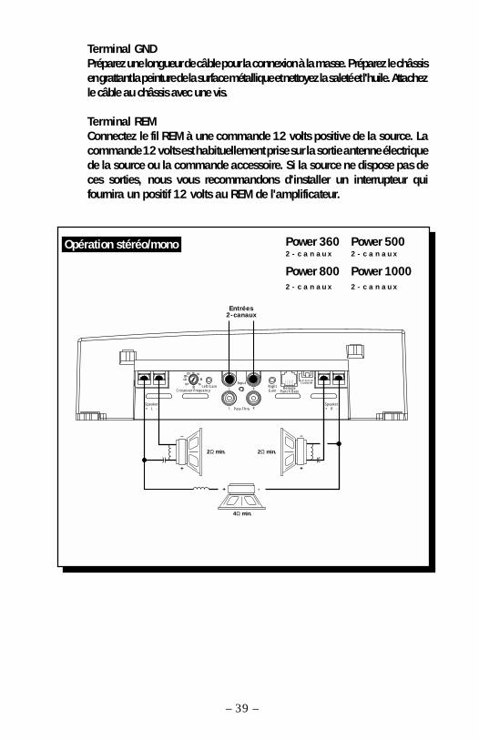
Terminal GNDPréparez une longueur de câble pour la connexion à la masse. Préparez le châssisen grattant la peinture de la surface métallique et nettoyez la saleté et l'huile. Attachezle câble au châssis avec une vis.
Terminal REMConnectez le fil REM à une commande 12 volts positive de la source. Lacommande 12 volts est habituellement prise sur la sortie antenne électriquede la source ou la commande accessoire. Si la source ne dispose pas deces sorties, nous vous recommandons d'installer un interrupteur quifournira un positif 12 volts au REM de l'amplificateur.
– 39 –
Opération stéréo/mono
Speaker+ L -
Crossover FrequencyLeft Gain
Input
Pass-Thru
L R
L R
RightGain
RemotePunch Bass
HP-Full-LPCrossover
Speaker+ R -
6580
55
50
110
210 Hz
145190
2Ω min.
Ent rées2-canaux
2Ω min.
–
+
–
+
4Ω min.
+ -
Power 360 Power 5002 - c a n a u x 2 - c a n a u x
Power 800 Power 10002 - c a n a u x 2 - c a n a u x
4-2Entrées
LED
LR+ LR- RR+ RR- B+ GND LF- LF+ RF+RF-
REM
FrontCrossoverHP-Full-LP
4/2Input
FrontGain Front
CrossoverFrequency
6580
55
50
110
210 Hz
145190
Front Pass-Thru Rear
R R
L L
RearCrossoverFrequency
6580
55
50
110
210 Hz
145190
RearGain
RearCrossoverHP-Full-LP Rear
RemotePunchBass
2Ω min.
+ -
2Ω min.
+ -
Ent rées4-Canaux
+ - + -
2Ω min.2Ω min.
– 40 –
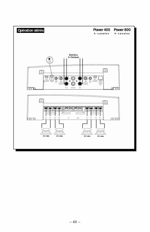
Opération stéréo Power 400 Power 800 4 - c a n a l e s 4 - c a n a l e s

BITTE LESEN SIE DIESE GEBRAUCHSANLEITUNG ZUERST SORGFÄLTIG DURCH.DAS KANN SIE VOR DEM FALSCHEN EINSATZ, AUSFALLEN ODER SOGARBESCHÄDIGUNG DES PRODUKTES ODER IHRES FAHRZEUGES SCHÜTZEN.
Im FahrzeugkofferraumDer vertikale Einbau der Endstufen, das bedeutet, dab die Kühlrippen von obennach unten verlaufen, gibt dem Verstärker die beste Kühlung.
Auf der BeifahrerseiteSollte der Verstärker auf der Beifahrerseite montiert werden, so ist es sehr wichtig,für eine ausreichende Kühlung zu sorgen. Sollte der Verstärker z.B. unter demBeifahrersitz montiert werden, sollte dem Kühlkörper mindestens ein Luftspaltvon 2.5 cm bleiben, um so für eine ausreichende Kühlung zu sorgen.
EinbauZur Sicherheit klemmen Sie den Negativ-Pol der Batterie während des gesamtenEinbaues ab.
B+ AnschluβDie Plus-Leitung MUβ ca. 45 cm nach dem Plus-Pol der Batterie abgesichertsein. Preparieren Si die Kabellängen und montieren Sie den Sicherungshalter imMotorraum. ALLE Verbindungen müssen wasserdicht sein.
EINBAUORT
Rockford Ingenieure haben die Power Verstärker entwickelt. Mit höchstemTechnologie-Standart, hervorragender Klangqualität, einfacher Handhabungund bester Servicefreundlichkeit Trans•ana/Trans•nova ist eine Nieder-VoltSchaltung im Vorverstärkerteil aller Pünch Verstärker die für kristallklaren Klangauch bei sehr hohen Lautstärken sorgt. TOPAZ, eine einzigartige Erdungsschaltungverhindert und unterdrückt Einstreuungen und Störungen die nur allzu oft CarAudio Systeme beeinträchtigen. Flexibilität durch die Vielfalt der Aktivweiche mitihren Lebensdauer durch die Schutzschaltung NOMAD und der Einsatz vonMOSFET Transistoren und DSM (Discrete Surface Mount), machen dieseVerstärker so effizient. Das Ergebnis all dieser Komponenten machen Power-Verstärker so einzigartig und in ihrer Klangqualität nahezu unschlagbar.
EINLEITUNG
– 41 –
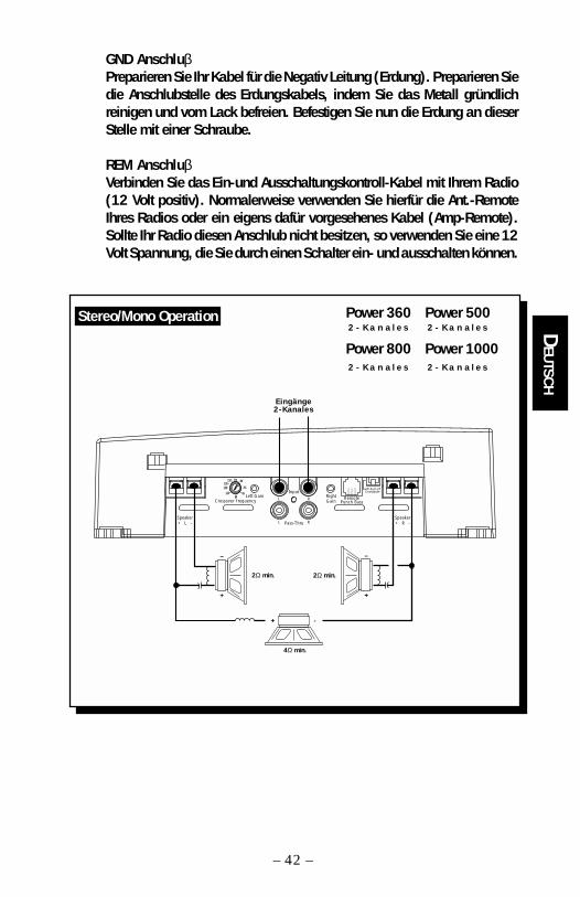
GND AnschluβPreparieren Sie Ihr Kabel für die Negativ Leitung (Erdung). Preparieren Siedie Anschlubstelle des Erdungskabels, indem Sie das Metall gründlichreinigen und vom Lack befreien. Befestigen Sie nun die Erdung an dieserStelle mit einer Schraube.
REM AnschluβVerbinden Sie das Ein-und Ausschaltungskontroll-Kabel mit Ihrem Radio(12 Volt positiv). Normalerweise verwenden Sie hierfür die Ant.-RemoteIhres Radios oder ein eigens dafür vorgesehenes Kabel (Amp-Remote).Sollte Ihr Radio diesen Anschlub nicht besitzen, so verwenden Sie eine 12Volt Spannung, die Sie durch einen Schalter ein- und ausschalten können.
– 42 –
DEUTSCH
Stereo/Mono Operation
Speaker+ L -
Crossover FrequencyLeft Gain
Input
Pass-Thru
L R
L R
RightGain
RemotePunch Bass
HP-Full-LPCrossover
Speaker+ R -
6580
55
50
110
210 Hz
145190
2Ω min.
Eingänge2-Kanales
2Ω min.
–
+
–
+
4Ω min.
+ -
Power 360 Power 500 2 - K a n a l e s 2 - K a n a l e s
Power 800 Power 1000 2 - K a n a l e s 2 - K a n a l e s
4-2Eingänge
FrontCrossoverHP-Full-LP
4/2Input
FrontGain Front
CrossoverFrequency
6580
55
50
110
210 Hz
145190
Front Pass-Thru Rear
R R
L L
RearCrossoverFrequency
6580
55
50
110
210 Hz
145190
RearGain
RearCrossoverHP-Full-LP Rear
RemotePunchBass
LED
LR+ LR- RR+ RR- B+ GND LF- LF+ RF+RF-
REM
2Ω min.
+ -
2Ω min.
+ -
Eingänge4-Kanales
+ - + -
2Ω min.2Ω min.
– 43 –
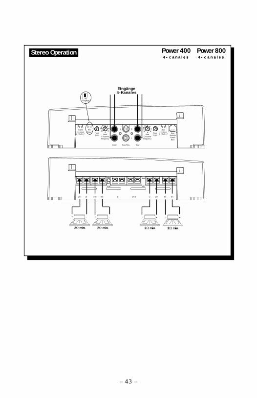
Stereo Operation Power 400 Power 800 4 - c a n a l e s 4 - c a n a l e s
ATTENZIONE: SI PREGA DI LEGGERE LE SEGUENTI ISTRUZIONI PER L'INSTALLAZIONEDI QUESTO PRODOTTO. IL NON SEGUIRLE POTREBBE RISULTARE SERIAMENTEDANNOSO PER LA PERSONA O PER IL VEICOLO.
Gli ingenieri Rockford hanno progettato la serie di amplificatori Power perresistere all'ostico ambiente automobilistico mentre suonano con una musicalitásuperiore, offrendo un insieme versatile, affidabile ed efficiente. Trans•ana/Trans•nova é un circuito a bassa tensione dello stadio preamplificatore delPunch che permette al suono di essere cristallino e reale anche in presenza divolumi molto elevati…tutto questo é accoppiato TOPAZ, un exclusivo circuitodi massa impiegato per eliminare i problemi di rumore comunemente presentinegli impianti car audio. L'affidabilitá é completamente garantita dall'impiegodi un circuito di protezione chiamato NOMAD, mentre l'uso di MOSFET e dellatecnologia DSM (Discrete Surface Mount) permette di raggiungere efficienzeelevatissime. Il risultato finale di tutte queste tecnnologie moderne é che gliamplificatori Power suonano meravigliosamente e sono indistruttibili, a “provadi proiettile.”
INTRODUZIONE
Nel BagagliaioMontando l'amplificatore su una superficie in verticale con le alette direzionatedall'alto verso il basso si garantirá un miglior raffreddamento dell'amplificatore.
Nell'abitacoloMontare l'amplificatore nell'abitacolo si avrá un funzionamento regolare se sigarantisce un flusso d'aria sufficiente. Per l'installazione sotto un sedile, énecessario avere uno spazio di almeno 2.5 cm attorno a tutto l'amplificatore.
InstallazionePer sicurezza, scollegare il polo negativo della batteria dell'auto prima diiniziare l'installazione.
Terminale B+ (cavo positivo)Il cavo positivo deve essere protetto da un fusibile a non piú di 45 cm dallabatteria. Terminare il cavo e installare il fusibile nel vano motore. Tutte leconnessioni devono essere a prova d'acqua.
DOVE POSIZIONARLO
– 44 –
I TALIANO
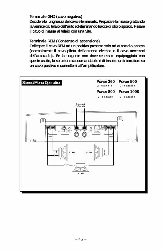
Terminale GND (cavo negativo)Decidere la lunghezza del cavo e terminarlo. Preparare la massa grattandola vernice dal telaio dell'auto ed eliminando tracce di olio o sporco. Fissareil cavo di massa al telaio con una vite.
Terminale REM (Consenso di accensione)Collegare il cavo REM ad un positivo presente solo ad autoradio accesa(normalmente il cavo pilota dell'antenna elettrica o il cavo accessoridell'autoradio). Se la sorgente non dovesse essere equipaggiata conqueste uscite, la soluzione raccomandabile é di inserire un interruttore suun cavo positivo e connettersi all'amplificatore.
– 45 –
Stereo/Mono Operation
Speaker+ L -
Crossover FrequencyLeft Gain
Input
Pass-Thru
L R
L R
RightGain
RemotePunch Bass
HP-Full-LPCrossover
Speaker+ R -
6580
55
50
110
210 Hz
145190
2Ω min.
Ingress i2-Canale
2Ω min.
–
+
–
+
4Ω min.
+ -
Power 360 Power 500 2 - c a n a l e 2 - c a n a l e
Power 800 Power 1000 2 - c a n a l e 2 - c a n a l e
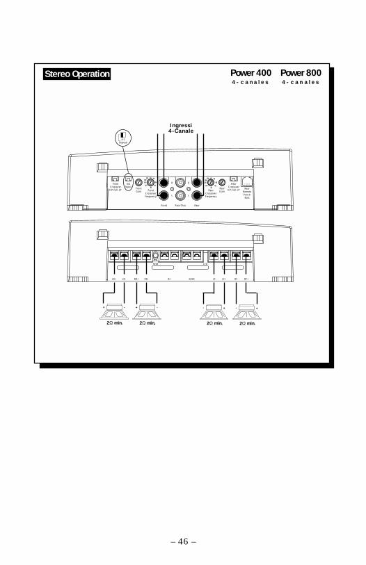
4-2Ingressi
FrontCrossoverHP-Full-LP
4/2Input
FrontGain Front
CrossoverFrequency
6580
55
50
110
210 Hz
145190
Front Pass-Thru Rear
R R
L L
RearCrossoverFrequency
6580
55
50
110
210 Hz
145190
RearGain
RearCrossoverHP-Full-LP Rear
RemotePunchBass
LED
LR+ LR- RR+ RR- B+ GND LF- LF+ RF+RF-
REM
2Ω min.
+ -
2Ω min.
+ -
Ingress i4-Canale
+ - + -
2Ω min.2Ω min.
– 46 –
Stereo Operation Power 400 Power 800 4 - c a n a l e s 4 - c a n a l e s
Installation assistance available at:
www.rockfordfosgate.com/rftech
10/99 E.W.R.MAN-2616-A
MADE IN THE USAThis product is designed, developed and assembled in the USA by a dedicated group of
American workers. The majority of the components used in the construction of this productare produced by American companies. However, due to the global nature of their
manufacturing facilities and the loudspeaker parts industry in general, some parts may bemanufactured in other countries.
Rockford FosgateRockford Corporation
546 South Rockford DriveTempe, Arizona 85281 U.S.A.
In U.S.A., (602) 967-3565In Europe, Fax (49) 8503-934014In Japan, Fax (81) 559-79-1265