Embed Size (px)
Citation preview
Save This Manual for Future Reference506 01 1901 007/26/02
3 PHASE, 10 TONHEAT PUMP
SPLIT SYSTEM
Installation, Start--Up, andService Instructions
Split System Heat PumpsInstallation Instructions
2 506 01 1901 00
Installation/ StartupInformationThese instructions must be read and understoodcompletely before attempting installation.
WARNINGInstallation or repairs made by unqualifiedpersons can result in hazards to you and others.Installation MUST conform with local buildingcodes or, in the absence of local codes, with thethe National Electrical Code NFPA 70/ANSIC1-1999 or current edition and CanadianElectrical Code Part 1 CSA C.22.1.
The information contained in this manual isintended for use by a qualified service technicianfamiliar with safety procedures and equippedwith the proper tools and test instruments.
Failure to carefully read and follow all instruc-tions in this manual can result in equipmentmalfunction, property damage, personal injuryand/or death.
After uncrating unit, inspect thoroughly for hidden damage.If damage is found, notify the transportation companyimmediately and file a concealed damage claim.
Top skid assembly should be left in place until after the unitis rigged into its final location.
CAUTION
Improper installation, adjustment, alteration, service ormaintenance can void the warranty.
The weight of the condensing unit requires caution andproper handling procedures when lifting or moving to avoidpersonal injury. Use care to avoid contact with sharp orpointed edges.
Safety Precautions1. Always wear safety eye wear and work gloves when
installing equipment.2. Never assumeelectrical power is disconnected.Check
with meter and disconnect.3. Keep hands out of fan areas when power is connected
to equipment.4. R--22 causes frost--bite burns.5. R--22 is toxic when burned.
Locating The Outdoor Unit:Check local codes covering zoning, noise, platforms.
If practical, avoid locating next to fresh air intakes, vent orwindows. Noise may carry into the openings and disturbpeople inside.
Placement of the unit should be in a well drained area orunit must be supported high enough so runoff will not enterthe unit.
Do not locate where heat, lint or exhaust fumes will bedischarged on unit (as from dryer vents).
Roof top installations are acceptable providing the roof willsupport the unit and provisions are made for waterdrainage and the noise or vibration through the structure.
Do not install the unit in a recessed or confined area whererecirculation of discharge air may occur.
Allow sufficient space for airflow clearance, wiring,refrigerant piping, and servicing unit.
Split System Heat Pumps Installation Instructions
3506 01 1901 00
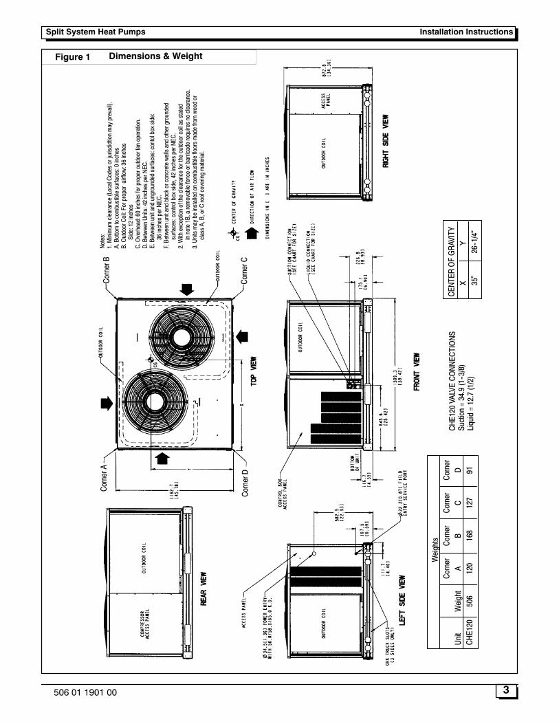
Figure 1 Dimensions & Weight
Weights
Corner
Corner
Corner
Corner
Unit
Weight
AB
CD
CHE120
506
120
168
127
91
CHE120VALVECO
NNECTIONS
Suction=34.9(1--3/8)
Liquid=12.7(1/2)
Notes:
1.Minimum
clearance(LocalCodesorjurisdidtionmayprevail).
A.Bottomtocombustiblesurfaces:0inches
B.OutdoorCoil:Forproperairflow:36inches
Side:12inches
C.Overhead:60inchesforproperoutdoorfanoperation.
D.BetweenUnits:42inchesperNEC.
E.Betweenunitandungroundedsurfaces:contolboxside:
36inchesperNEC.
F.Betweenunitandblockorconcretewallsandothergrounded
surfaces:controlboxside,42inchesperNEC.
2.Withexceptionoftheclearancefortheoutdoorcoilasstated
innote1B,aremovablefenceorbarricaderequiresnoclearance.
3.Unitsmaybeinstalledoncombustiblefloorsmadefromwoodor
classA,B,orCroofcoveringmaterial.
CENTER
OFGRAVITY
XY
35�
26--1/4�
CornerA
CornerB
CornerC
CornerD
Split System Heat PumpsInstallation Instructions
4 506 01 1901 00
Rig and Mount the Unit:CAUTION
Be sure unit panels are securely in place prior torigging.
RIGGING -- These units are designed for overhead rigging.Refer to rigging label for preferred rigging method.Spreader bars are not required if top crating is left on unit.All panels must be in place when rigging. As furtherprotection for coil faces, plywood sheets may be placedagainst sides of unit, behind cables. Run cables to a centralsuspension point so that angle from the horizontal is notless than 45 degrees. Raise and set unit down carefully.
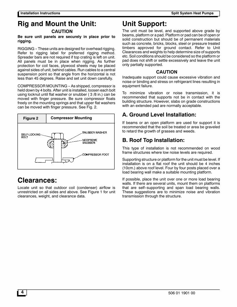
COMPRESSORMOUNTING -- As shipped, compressor isheld down by 4 bolts. After unit is installed, loosen each boltusing locknut until flat washer or snubber ( 3 /8 in.) can bemoved with finger pressure. Be sure compressor floatsfreely on the mounting springs and that upper flat washerscan be moved with finger pressure. See Fig. 2.
Compressor MountingFigure 2
Clearances:Locate unit so that outdoor coil (condenser) airflow isunrestricted on all sides and above. See Figure 1 for unitclearances, weight, and clearance data.
Unit Support:The unit must be level, and supported above grade bybeams, platform or a pad. Platformor pad can be of open orsolid construction but should be of permanent materialssuch as concrete, bricks, blocks, steel or pressure treatedtimbers approved for ground contact. Refer to UnitClearances andweights to help determine size of supportsetc. Soil conditions should be considered so the platform orpad does not shift or settle excessively and leave the unitonly partially supported.
CAUTIONInadequate support could cause excessive vibration andnoise or binding and stress on refrigerant lines resulting inequipment failure.
To minimize vibration or noise transmission, it isrecommended that supports not be in contact with thebuilding structure. However, slabs on grade constructionswith an extended pad are normally acceptable.
A. Ground Level Installation:If beams or an open platform are used for support it isrecommended that the soil be treated or area be graveledto retard the growth of grasses and weeds.
B. Roof Top Installation:This type of installation is not recommended on woodframe structures where low noise levels are required.
Supporting structure or platform for the unit must be level. Ifinstallation is on a flat roof the unit should be 4 inches(10cm.) above roof level. Four by four posts placed over aload bearing wall make a suitable mounting platform.
If possible, place the unit over one or more load bearingwalls. If there are several units, mount them on platformsthat are self--supporting and span load bearing walls.These suggestions are to minimize noise and vibrationtransmission through the structure.
Split System Heat Pumps Installation Instructions
5506 01 1901 00
Installing Refrigerant LinesComplete Refrigerant PipingConnectionsIMPORTANT: A refrigeratn receiver is not providedwith theunit. Do not install a receiver.
SIZE REFRIGERANT LINES -- Consider the length of thepiping required between the outdoor and indoor units. Themaximumallowable line length is 100 ft (30.5m). SeeTable1. Refrigerant suction piping should be insulated.
NOTE: Use the piping data in Table 1 as a general guideonly. For CHE120 applications with liquid lift greater than20 ft, use 5/8 --in. liquid line. Maximum lift is 60 ft.
Table 1 -- Refrigerant Piping Sizes
Linear Length of Interconnecting Piping -- Ft. (mm)
0 -- 25(0 -- 7.5)
25 -- 50(7.5 -- 15)
50 -- 75(15 -- 23 )
75 -- 100(23 -- 30)
Line Size (in. OD)
Unit L S L S L S L S
CHE120 1/2 1--3/8 1/2 1--3/8 1/2 1--3/8 1/2 1--3/8
* Field--supplied suction accumulator required for pipelength 75--100 ft.
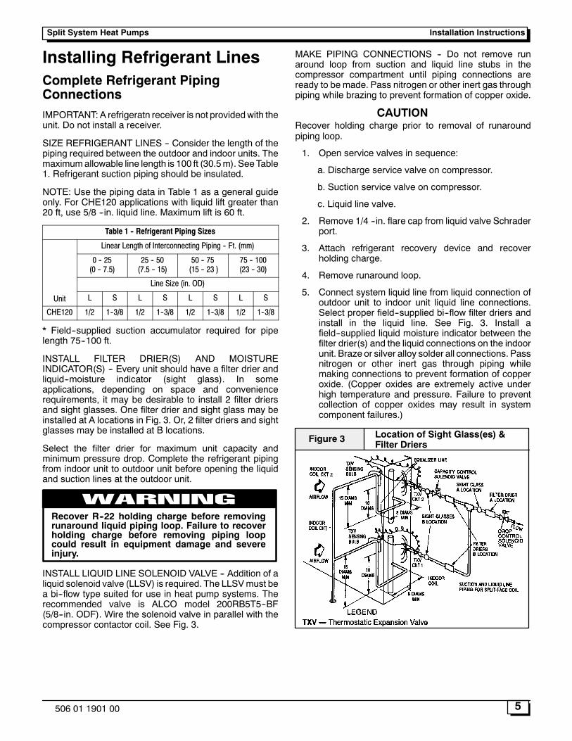
INSTALL FILTER DRIER(S) AND MOISTUREINDICATOR(S) -- Every unit should have a filter drier andliquid--moisture indicator (sight glass). In someapplications, depending on space and conveniencerequirements, it may be desirable to install 2 filter driersand sight glasses. One filter drier and sight glass may beinstalled at A locations in Fig. 3. Or, 2 filter driers and sightglasses may be installed at B locations.
Select the filter drier for maximum unit capacity andminimum pressure drop. Complete the refrigerant pipingfrom indoor unit to outdoor unit before opening the liquidand suction lines at the outdoor unit.
WARNINGRecover R--22 holding charge before removingrunaround liquid piping loop. Failure to recoverholding charge before removing piping loopcould result in equipment damage and severeinjury.
INSTALL LIQUID LINE SOLENOID VALVE -- Addition of aliquid solenoid valve (LLSV) is required. The LLSVmust bea bi--flow type suited for use in heat pump systems. Therecommended valve is ALCO model 200RB5T5--BF(5/8--in. ODF). Wire the solenoid valve in parallel with thecompressor contactor coil. See Fig. 3.
MAKE PIPING CONNECTIONS -- Do not remove runaround loop from suction and liquid line stubs in thecompressor compartment until piping connections areready to be made. Pass nitrogen or other inert gas throughpiping while brazing to prevent formation of copper oxide.
CAUTIONRecover holding charge prior to removal of runaroundpiping loop.
1. Open service valves in sequence:
a. Discharge service valve on compressor.
b. Suction service valve on compressor.
c. Liquid line valve.
2. Remove 1/4 --in. flare cap from liquid valve Schraderport.
3. Attach refrigerant recovery device and recoverholding charge.
4. Remove runaround loop.
5. Connect system liquid line from liquid connection ofoutdoor unit to indoor unit liquid line connections.Select proper field--supplied bi--flow filter driers andinstall in the liquid line. See Fig. 3. Install afield--supplied liquid moisture indicator between thefilter drier(s) and the liquid connections on the indoorunit. Braze or silver alloy solder all connections. Passnitrogen or other inert gas through piping whilemaking connections to prevent formation of copperoxide. (Copper oxides are extremely active underhigh temperature and pressure. Failure to preventcollection of copper oxides may result in systemcomponent failures.)
Location of Sight Glass(es) &Filter Driers
Figure 3
Split System Heat PumpsInstallation Instructions
6 506 01 1901 00
Electrical Wiring
Electrical Shock Hazard.
Shut off electric power at fuse box or service pan-el before making any electrical connections.
Failure to shut off electric power can result in,property damage, personal injury and/or death.
WARNING
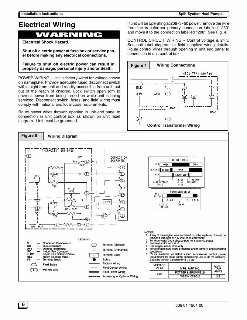
POWERWIRING -- Unit is factory wired for voltage shownon nameplate. Provide adequate fused disconnect switchwithin sight from unit and readily accessible from unit, butout of the reach of children. Lock switch open (off) toprevent power from being turned on while unit is beingserviced. Disconnect switch, fuses, and field wiring mustcomply with national and local code requirements.
Route power wires through opening in unit end panel toconnection in unit control box as shown on unit labeldiagram. Unit must be grounded.
If unit will be operating at 208--3--60 power, remove thewirefrom the transformer primary connection labelled ��230�and move it to the connection labelled ��208�. See Fig. 4.
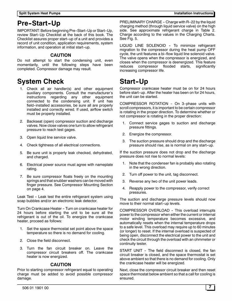
CONTROL CIRCUIT WIRING -- Control voltage is 24 v.See unit label diagram for field--supplied wiring details.Route control wires through opening in unit end panel toconnection in unit control box.
Figure 4 Wiring Connections
Control Transformer Wiring
Figure 5 Wiring Diagram
Split System Heat Pumps Installation Instructions
7506 01 1901 00
Pre--Start--UpIMPORTANT: Before beginning Pre--Start--Up or Start--Up,review Start--Up Checklist at the back of this book. TheChecklist assures proper start--up of a unit and provides arecord of unit condition, application requirements, systeminformation, and operation at initial start--up.
CAUTIONDo not attempt to start the condensing unit, evenmomentarily, until the following steps have beencompleted. Compressor damage may result.
System Check1. Check all air handler(s) and other equipment
auxiliary components. Consult the manufacturer�sinstructions regarding any other equipmentconnected to the condensing unit. If unit hasfield--installed accessories, be sure all are properlyinstalled and correctly wired. If used, airflow switchmust be properly installed.
2. Backseat (open) compressor suction and dischargevalves. Now close valves one turn to allow refrigerantpressure to reach test gages.
3. Open liquid line service valve.
4. Check tightness of all electrical connections.
5. Be sure unit is properly leak checked, dehydrated,and charged.
6. Electrical power source must agree with nameplaterating.
7. Be sure compressor floats freely on the mountingsprings and that snubberwashers can bemovedwithfinger pressure. See Compressor Mounting Sectionon page 4.
Leak Test -- Leak test the entire refrigerant system usingsoap bubbles and/or an electronic leak detector.
Turn On Crankcase Heater -- Turn on crankcase heater for24 hours before starting the unit to be sure all therefrigerant is out of the oil. To energize the crankcaseheater, proceed as follows:
1. Set the space thermostat set point above the spacetemperature so there is no demand for cooling.
2. Close the field disconnect.
3. Turn the fan circuit breaker on. Leave thecompressor circuit breakers off. The crankcaseheater is now energized.
CAUTIONPrior to starting compressor refrigerant equal to operatingcharge must be added to avoid possible compressordamage.
PRELIMINARYCHARGE -- Charge with R--22 by the liquidcharging method (through liquid service valve) on the highside. See approximate refrigerant charge in Table 2.Charge according to the values in the Charging Charts.See Fig. 5.
LIQUID LINE SOLENOID -- To minimize refrigerantmigration to the compressor during the heat pump OFFcycle, the unit features a bi--flow liquid line solenoid valve.The valve opens when the compressor is energized, andcloses when the compressor is deenergized. This featurereduces compressor flooded starts, significantlyincreasing compressor life.
Start--UpCompressor crankcase heater must be on for 24 hoursbefore start--up. After the heater has been on for 24 hours,the unit can be started.
COMPRESSOR ROTATION -- On 3--phase units withscroll compressors, it is important to be certain compressoris rotating in the proper direction. To determine whether ornot compressor is rotating in the proper direction:
1. Connect service gages to suction and dischargepressure fittings.
2. Energize the compressor.
3. The suction pressure should drop and the dischargepressure should rise, as is normal on any start--up.
If the suction pressure does not drop and the dischargepressure does not rise to normal levels:
1. Note that the condenser fan is probably also rotatingin the wrong direction.
2. Turn off power to the unit, tag disconnect.
3. Reverse any two of the unit power leads.
4. Reapply power to the compressor, verify correctpressures.
The suction and discharge pressure levels should nowmove to their normal start--up levels.
COMPRESSOR OVERLOAD -- This overload interruptspower to the compressor wheneither the current or internalmotor winding temperature becomes excessive, andautomatically resets when the internal temperature dropsto a safe level. This overload may require up to 60 minutes(or longer) to reset. If the internal overload is suspected ofbeing open, disconnect the electrical power to the unit andcheck the circuit through the overload with an ohmmeter orcontinuity tester.
START UNIT -- The field disconnect is closed, the fancircuit breaker is closed, and the space thermostat is setabove ambient so that there is no demand for cooling. Onlythe crankcase heater will be energized.
Next, close the compressor circuit breaker and then resetspace thermostat below ambient so that a call for cooling isensured.
Split System Heat PumpsInstallation Instructions
8 506 01 1901 00
NOTE: Do not use circuit breaker to start and stop thecompressor except in an emergency.
After starting, there is a delay of at least 3 seconds beforecompressor starts.
CAUTIONNever charge liquid into the low--pressure side of system.Do not overcharge. During charging or removal ofrefrigerant, be sure indoor--fan system is operating.
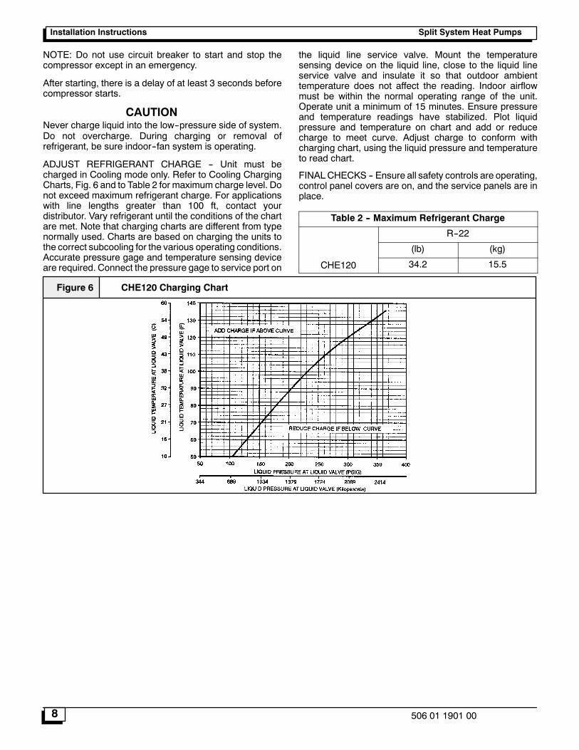
ADJUST REFRIGERANT CHARGE -- Unit must becharged in Cooling mode only. Refer to Cooling ChargingCharts, Fig. 6 and to Table 2 for maximum charge level. Donot exceed maximum refrigerant charge. For applicationswith line lengths greater than 100 ft, contact yourdistributor. Vary refrigerant until the conditions of the chartare met. Note that charging charts are different from typenormally used. Charts are based on charging the units tothe correct subcooling for the various operating conditions.Accurate pressure gage and temperature sensing deviceare required. Connect the pressure gage to service port on
the liquid line service valve. Mount the temperaturesensing device on the liquid line, close to the liquid lineservice valve and insulate it so that outdoor ambienttemperature does not affect the reading. Indoor airflowmust be within the normal operating range of the unit.Operate unit a minimum of 15 minutes. Ensure pressureand temperature readings have stabilized. Plot liquidpressure and temperature on chart and add or reducecharge to meet curve. Adjust charge to conform withcharging chart, using the liquid pressure and temperatureto read chart.
FINALCHECKS -- Ensure all safety controls are operating,control panel covers are on, and the service panels are inplace.
Table 2 -- Maximum Refrigerant Charge
R--22
(lb) (kg)
CHE120 34.2 15.5
CHE120 Charging ChartFigure 6
Split System Heat Pumps Installation Instructions
9506 01 1901 00
Operating SequenceWhen power is supplied to unit, the transformer (TRAN) isenergized. The crankcase heater is also energized.
CoolingWith the thermostat subbase in the cooling position, andwhen the space temperature comeswithin 2�F (1�C) of thecooling set point, the thermostat makes circuit R--O. Thisenergizes the reversing valve solenoid (RVS) and placesthe unit in standby condition for cooling.
As the space temperature continues to rise, the secondstage of the thermostat makes, closing circuit R--Y. Whencompressor time delay (5 +/-- 2 minutes) is completed, acircuit is made to contactor (C), starting the compressor(COMP) and outdoor fan motor (OFM). Circuit R--G ismade at the same time, energizing the indoor fan contactor(IFC) and starting the indoor fan motor (IFM) after onesecond delay.
When the thermostat is satisfied, contacts open,deenergizing C. The COMP, IFM, and OFM stop.
HeatingOna call for heat, thermostatmakes circuits R--Y andR--G.When compressor time delay (5 +/-- 2 minutes) iscompleted, a circuit ismade toC, startingCOMPandOFM.Circuit R--G also energizes IFC and starts IFM after a 1second delay.
ServiceCrankcase Heater -- The heater prevents refrigerantmigration and compressor oil dilution during shutdownwhenever compressor is not operating. It is wired to cyclewith the compressor; the heater is off when compressor isrunning, and on when compressor is off.
Both compressor service valves must be closed wheneverthe crankcase heater is deenergized formore than 6 hours.The crankcase heater is operable as long as the controlcircuit is energized.
Compressor Protection
COMPRESSOR OVERTEMPERATURE PROTECTION(IP) -- A thermostat installed on compressor motor windingreacts to excessively high winding temperatures and shutsoff the compressor.
CRANKCASE HEATER -- Heater minimizes absorption ofliquid refrigerant by oil in crankcase during brief orextended shutdown periods. The control circuit ismaintained if compressor fan motor circuit breakers areturned off. The main disconnect must be on to energizecrankcase heater.
High--Pressure Switches -- Switches have fixed,nonadjustable settings. Switches are mounted on thecompressors.
Low--Pressure Switches -- Switches have fixed,non--adjustable settings. Switches are mounted on thecompressors.TO CHECK -- Slowly close liquid shutoff valve and allowcompressor to pump down. Do not allow compressorpumpdown below 2 psig (13.8 kPa). Compressor shouldshut down when suction pressure drops to cutout pressurein specification sheet tables, and should restart whenpressure builds up to cut--in pressure shown.
Outdoor Fans -- Each fan is supported by a formed--wiremount bolted to the fan deck and coveredwith awire guard.Fan motors have permanently lubricated bearings.
Split System Heat PumpsInstallation Instructions
10 506 01 1901 00
LubricationFAN MOTORS have sealed bearings. No provisions aremade for lubrication.
COMPRESSOR has its own oil supply. Loss of oil due to aleak in the system should be the only reason for adding oilafter the system has been in operation.
Coil Cleaning and Maintenance -- Routine cleaning of coilsurfaces is essential to minimize contamination build--upand remove harmful residue. Inspect coils monthly andclean as required.
CLEANING COILS -- Coils can be cleaned with a vacuumcleaner, washed out with low velocity water, blown out withlow--pressure compressed air, or brushed (do not use wirebrush). Fan motors are drip--proof but not waterproof. DoNOT use acid cleaners.
Clean outdoor coil annually or as required by location oroutdoor air conditions. Inspect coil monthly, and clean asrequired. Fins are not continuous through coil sections; dirtand debris may pass through first section, become trappedbetween 2nd and 3rd rows of fins and restrict outdoorairflow. Use a flashlight to determine if dirt or debris hascollected between coil sections. Clean coil as follows:
1. Turn off unit power.
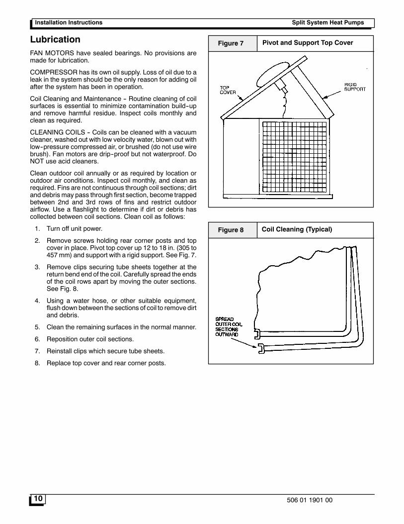
2. Remove screws holding rear corner posts and topcover in place. Pivot top cover up 12 to 18 in. (305 to457mm) and support with a rigid support. See Fig. 7.
3. Remove clips securing tube sheets together at thereturn bend end of the coil. Carefully spread the endsof the coil rows apart by moving the outer sections.See Fig. 8.
4. Using a water hose, or other suitable equipment,flush down between the sections of coil to remove dirtand debris.
5. Clean the remaining surfaces in the normal manner.
6. Reposition outer coil sections.
7. Reinstall clips which secure tube sheets.
8. Replace top cover and rear corner posts.
Pivot and Support Top CoverFigure 7
Coil Cleaning (Typical)Figure 8
Split System Heat Pumps Installation Instructions
11506 01 1901 00
Split System Heat PumpsInstallation Instructions
12 506 01 1901 00
Split System Heat Pumps Installation Instructions
13506 01 1901 00
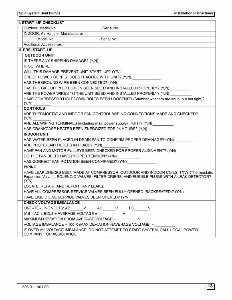
I. START--UP CHECKLISTOutdoor: Model No. Serial No.INDOOR: Air Handler Manufacturer --
Model No. Serial No.Additional Accessories:
II. PRE--START--UPOUTDOOR UNITIS THERE ANY SHIPPING DAMAGE? (Y/N)IF SO, WHERE:WILL THIS DAMAGE PREVENT UNIT START--UP? (Y/N)CHECK POWER SUPPLY. DOES IT AGREE WITH UNIT? (Y/N)HAS THE GROUND WIRE BEEN CONNECTED? (Y/N)HAS THE CIRCUIT PROTECTION BEEN SIZED AND INSTALLED PROPERLY? (Y/N)ARE THE POWER WIRES TO THE UNIT SIZED AND INSTALLED PROPERLY? (Y/N)HAVE COMPRESSOR HOLDDOWN BOLTS BEEN LOOSENED (Snubber washers are snug, but not tight)?(Y/N)CONTROLSARE THERMOSTAT AND INDOOR FAN CONTROL WIRING CONNECTIONS MADE AND CHECKED?(Y/N)ARE ALL WIRING TERMINALS (including main power supply) TIGHT? (Y/N)HAS CRANKCASE HEATER BEEN ENERGIZED FOR 24 HOURS? (Y/N)INDOOR UNITHAS WATER BEEN PLACED IN DRAIN PAN TO CONFIRM PROPER DRAINAGE? (Y/N)ARE PROPER AIR FILTERS IN PLACE? (Y/N)HAVE FAN AND MOTOR PULLEYS BEEN CHECKED FOR PROPER ALIGNMENT? (Y/N)DO THE FAN BELTS HAVE PROPER TENSION? (Y/N)HAS CORRECT FAN ROTATION BEEN CONFIRMED? (Y/N)PIPINGHAVE LEAK CHECKS BEEN MADE AT COMPRESSOR, OUTDOOR AND INDOOR COILS, TXVs (ThermostaticExpansion Valves), SOLENOID VALVES, FILTER DRIERS, AND FUSIBLE PLUGS WITH A LEAK DETECTOR?(Y/N)LOCATE, REPAIR, AND REPORT ANY LEAKS.HAVE ALL COMPRESSOR SERVICE VALVES BEEN FULLY OPENED (BACKSEATED)? (Y/N)HAVE LIQUID LINE SERVICE VALVES BEEN OPENED? (Y/N)CHECK VOLTAGE IMBALANCELINE--TO--LINE VOLTS: AB V AC V BC V(AB + AC + BC)/3 = AVERAGE VOLTAGE = VMAXIMUM DEVIATION FROM AVERAGE VOLTAGE = VVOLTAGE IMBALANCE = 100 X (MAX DEVIATION)/(AVERAGE VOLTAGE) =IF OVER 2% VOLTAGE IMBALANCE, DO NOT ATTEMPT TO START SYSTEM! CALL LOCAL POWERCOMPANY FOR ASSISTANCE.
Split System Heat PumpsInstallation Instructions
14 506 01 1901 00
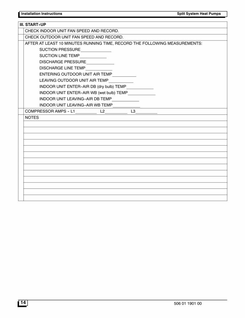
III. START--UP
CHECK INDOOR UNIT FAN SPEED AND RECORD.
CHECK OUTDOOR UNIT FAN SPEED AND RECORD.
AFTER AT LEAST 10 MINUTES RUNNING TIME, RECORD THE FOLLOWING MEASUREMENTS:
SUCTION PRESSURE
SUCTION LINE TEMP
DISCHARGE PRESSURE
DISCHARGE LINE TEMP
ENTERING OUTDOOR UNIT AIR TEMP
LEAVING OUTDOOR UNIT AIR TEMP
INDOOR UNIT ENTER--AIR DB (dry bulb) TEMP
INDOOR UNIT ENTER--AIR WB (wet bulb) TEMP
INDOOR UNIT LEAVING--AIR DB TEMP
INDOOR UNIT LEAVING--AIR WB TEMP
COMPRESSOR AMPS -- L1 L2 L3
NOTES
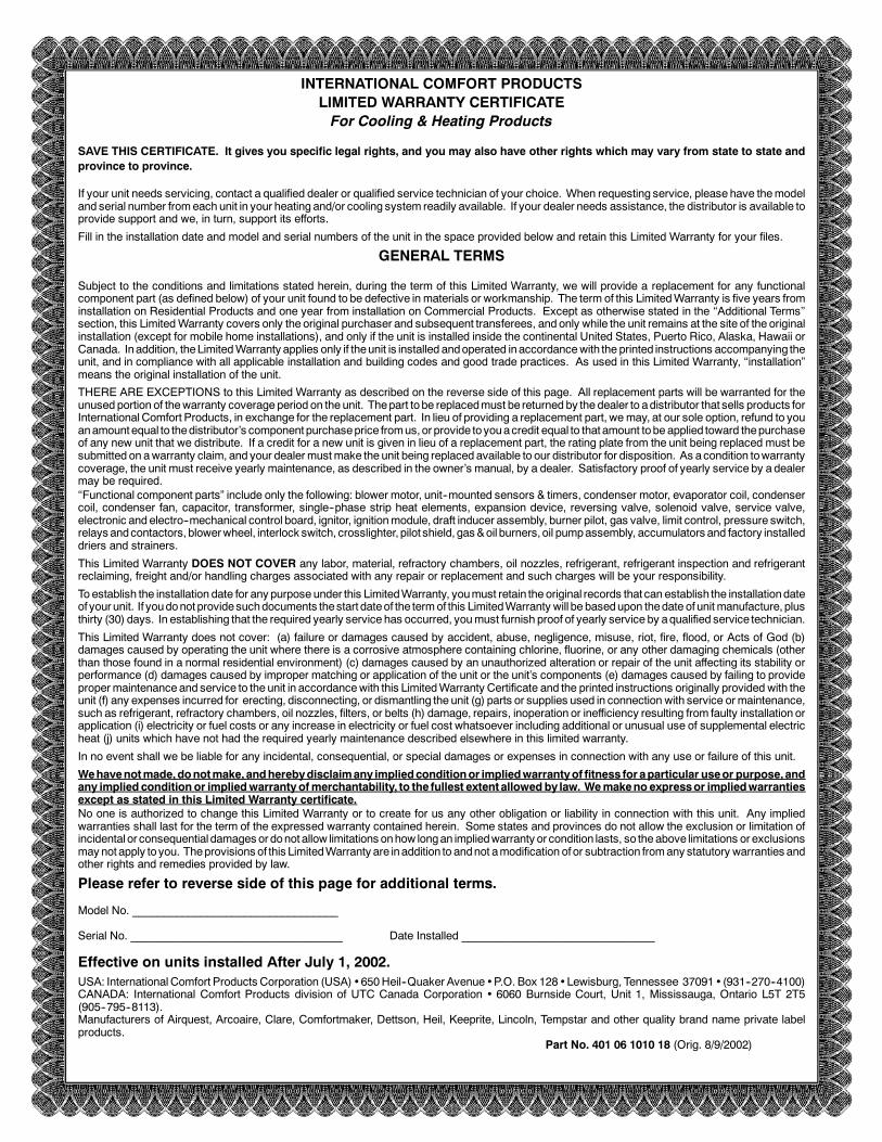
INTERNATIONAL COMFORT PRODUCTSLIMITED WARRANTY CERTIFICATEFor Cooling & Heating Products
SAVE THIS CERTIFICATE. It gives you specific legal rights, and you may also have other rights which may vary from state to state andprovince to province.
If your unit needs servicing, contact a qualified dealer or qualified service technician of your choice. When requesting service, please have themodeland serial number fromeach unit in your heating and/or cooling system readily available. If your dealer needs assistance, the distributor is available toprovide support and we, in turn, support its efforts.
Fill in the installation date and model and serial numbers of the unit in the space provided below and retain this Limited Warranty for your files.
GENERAL TERMS
Subject to the conditions and limitations stated herein, during the term of this Limited Warranty, we will provide a replacement for any functionalcomponent part (as defined below) of your unit found to be defective in materials or workmanship. The term of this LimitedWarranty is five years frominstallation on Residential Products and one year from installation on Commercial Products. Except as otherwise stated in the ��Additional Terms��section, this LimitedWarranty covers only the original purchaser and subsequent transferees, and only while the unit remains at the site of the originalinstallation (except for mobile home installations), and only if the unit is installed inside the continental United States, Puerto Rico, Alaska, Hawaii orCanada. Inaddition, theLimitedWarranty applies only if theunit is installed andoperated inaccordancewith the printed instructions accompanying theunit, and in compliance with all applicable installation and building codes and good trade practices. As used in this Limited Warranty, ��installation�means the original installation of the unit.
THERE ARE EXCEPTIONS to this Limited Warranty as described on the reverse side of this page. All replacement parts will be warranted for theunused portion of thewarranty coverage period on the unit. Thepart tobe replacedmust be returned by the dealer to adistributor that sells products forInternational Comfort Products, in exchange for the replacement part. In lieu of providing a replacement part, wemay, at our sole option, refund to youanamountequal to thedistributor�s component purchaseprice fromus, or provide toyouacredit equal to that amount tobe applied toward thepurchaseof any new unit that we distribute. If a credit for a new unit is given in lieu of a replacement part, the rating plate from the unit being replaced must besubmitted on awarranty claim, and your dealermustmake the unit being replaced available to our distributor for disposition. As acondition towarrantycoverage, the unit must receive yearly maintenance, as described in the owner�s manual, by a dealer. Satisfactory proof of yearly service by a dealermay be required.��Functional component parts� include only the following: blower motor, unit--mounted sensors & timers, condenser motor, evaporator coil, condensercoil, condenser fan, capacitor, transformer, single--phase strip heat elements, expansion device, reversing valve, solenoid valve, service valve,electronic and electro--mechanical control board, ignitor, ignitionmodule, draft inducer assembly, burner pilot, gas valve, limit control, pressure switch,relays andcontactors, blowerwheel, interlock switch, crosslighter, pilot shield, gas&oil burners, oil pumpassembly, accumulators and factory installeddriers and strainers.
This Limited Warranty DOES NOT COVER any labor, material, refractory chambers, oil nozzles, refrigerant, refrigerant inspection and refrigerantreclaiming, freight and/or handling charges associated with any repair or replacement and such charges will be your responsibility.
To establish the installation date for any purpose under this LimitedWarranty, youmust retain the original records that can establish the installationdateof your unit. If youdonot providesuchdocuments thestart dateof the termof this LimitedWarranty will be basedupon thedate of unit manufacture, plusthirty (30) days. In establishing that the required yearly service has occurred, youmust furnish proof of yearly service by aqualified service technician.
This Limited Warranty does not cover: (a) failure or damages caused by accident, abuse, negligence, misuse, riot, fire, flood, or Acts of God (b)damages caused by operating the unit where there is a corrosive atmosphere containing chlorine, fluorine, or any other damaging chemicals (otherthan those found in a normal residential environment) (c) damages caused by an unauthorized alteration or repair of the unit affecting its stability orperformance (d) damages caused by improper matching or application of the unit or the unit�s components (e) damages caused by failing to providepropermaintenance and service to the unit in accordancewith this LimitedWarranty Certificate and the printed instructions originally provided with theunit (f) any expenses incurred for erecting, disconnecting, or dismantling the unit (g) parts or supplies used in connection with service ormaintenance,such as refrigerant, refractory chambers, oil nozzles, filters, or belts (h) damage, repairs, inoperation or inefficiency resulting from faulty installation orapplication (i) electricity or fuel costs or any increase in electricity or fuel cost whatsoever including additional or unusual use of supplemental electricheat (j) units which have not had the required yearly maintenance described elsewhere in this limited warranty.
In no event shall we be liable for any incidental, consequential, or special damages or expenses in connection with any use or failure of this unit.
Wehavenotmade,donotmake,andherebydisclaimany impliedconditionor impliedwarrantyof fitness for aparticular useor purpose,andany implied condition or impliedwarranty ofmerchantability, to the fullest extent allowedby law. Wemakeno expressor impliedwarrantiesexcept as stated in this Limited Warranty certificate.No one is authorized to change this Limited Warranty or to create for us any other obligation or liability in connection with this unit. Any impliedwarranties shall last for the term of the expressed warranty contained herein. Some states and provinces do not allow the exclusion or limitation ofincidental or consequential damages or donot allow limitations onhow longan impliedwarranty or condition lasts, so the above limitations or exclusionsmaynot apply toyou. Theprovisions of this LimitedWarranty are inaddition to andnot amodification of or subtraction fromany statutory warranties andother rights and remedies provided by law.
Please refer to reverse side of this page for additional terms.
Model No. _________________________________
Serial No. __________________________________ Date Installed _______________________________
Effective on units installed After July 1, 2002.USA: International Comfort Products Corporation (USA) �650Heil--Quaker Avenue �P.O. Box 128 �Lewisburg, Tennessee 37091 � (931--270--4100)CANADA: International Comfort Products division of UTC Canada Corporation � 6060 Burnside Court, Unit 1, Mississauga, Ontario L5T 2T5(905--795--8113).Manufacturers of Airquest, Arcoaire, Clare, Comfortmaker, Dettson, Heil, Keeprite, Lincoln, Tempstar and other quality brand name private labelproducts.
Part No. 401 06 1010 18 (Orig. 8/9/2002)
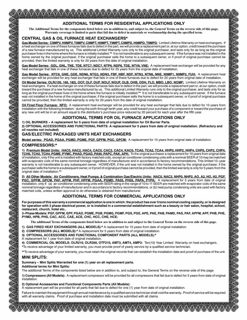
ADDITIONAL TERMS FOR RESIDENTIAL APPLICATIONS ONLYThe Additional Terms for the components listed below are in addition to, and subject to, the General Terms on the reverse side of this page.
Warranty coverage is limited to parts that fail due to defect in materials or workmanship during the specified term.
CENTRAL GAS & OIL FURNACE HEAT EXCHANGERS*GasModel Series: C9MPV,H9MPV, T9MPV,C9MPT,H9MPT, T9MPT,C9MPD,H9MPD, T9MPD: Limited LifetimeWarranty on heat exchangers. Ifa heat exchanger on one of these furnaces fails due to defect in the part, wewill provide a replacement part or, at our option, credit toward the purchaseof a new furnace manufactured by us. This additional Limited Warranty runs only to the original purchaser, and lasts only for as long as the originalpurchaser lives in thehomewhere the furnace is initially installed.** It is not transferable to any subsequent owner. If the furnacewas not installed in thehome owned by the original purchaser, if the original purchaser sells the home to a subsequent owner, or if proof of original purchase cannot beprovided, then the limited warranty is only for 20 years from the date of original installation.
Gas Model Series: GDL, GNL, TNE, TDE, NTC7, NDC7, NTP6, NDP6, TDE, NTV6, VNE: A replacement heat exchanger will be provided for anyheat exchanger that fails in one of these furnaces due to defect for 25 years from the original date of installation.
Gas Model Series: NTC6, GNE, GDE, NDN6, NTG3, NDN3, FBF, NBF, NDF, NTN3, NTN6, NNE, N9MP1, N9MP2, FUH: A replacement heatexchanger will be provided for any heat exchanger that fails in one of these furnaces due to defect for 20 years from original date of installation.Oil Model Series: OLR(105, 160, 182), OCF, OLF, OUF, NOLF, NOUF, OLB, OHB, ODH, FLO, MBO, LBO, NOMF: Limited Lifetime Warranty onheat exchangers. If a heat exchanger on one of these furnaces fails due to defect in the part, we will provide a replacement part or, at our option, credittoward the purchase of a new furnacemanufactured by us. This additional Limited Warranty runs only to the original purchaser, and lasts only for aslong as the original purchaser lives in the homewhere the furnace is initially installed.** It is not transferable to any subsequent owner. If the furnacewas not installed in the home of the original purchaser, if the original purchaser sells the home to a subsequent owner, or if proof of original purchasecannot be provided, then the limited warranty is only for 20 years from the date of original installation.
Oil Fired Floor Furnace: NFO: A replacement heat exchanger will be provided for any heat exchanger that fails due to defect for 10 years frominstallation with the following limitation: during the sixth through tenth year, any credit toward your purchase of a component or toward the purchase ofany new unit will be in an amount equal to the distributor�s purchase price reduced by 20 percent for each year after the fifth year.
ADDITIONAL TERMS FOR OIL FURNACE APPLICATIONS ONLY1) OIL BURNERS -- A replacement for 5 years from date of original installation for Oil Burner Parts.2) OPTIONAL ACCESSORIES AND FUNCTIONAL PARTS: A replacement for 5 years from date of original installation. (Refractory andoil nozzles not included)GAS/ELECTRIC PACKAGED UNITS HEAT EXCHANGERSModel series: PGAD, PGAA, PGMD, PGME, PGF, GPFM, PGC, GPCM: A replacement for 10 years from original date of installation.
COMPRESSORS:*1) Premium Model Units: HAC0, HAC2, HAC4, CAC0, CAC2, CAC4, KAC0, TCA0, TCA2, TCA4, HHP0, HHP2, HHP4, CHP0, CHP2, CHP4,TCH0, TCH2, TCH4, PGME, PYMC, PHAD, PGAD, PA95, PAPC, PAK,APK: To the original purchaser a replacement for 10 years fromoriginal dateof installation, only if the unit is installedwith factory matched coils, except air conditioner condensing unitswith anominal SEERof 10may bematchedwith evaporator coils of the same nominal tonnage regardless of manufacturer and in accordance to factory recommendations. This limited 10--yearwarranty is not transferable to any subsequent owner. HOWEVER, if the unit was not installed in the home owned by the original purchaser, if thepurchaser sells thehome toasubsequent owner, or if proof of original purchasecannot be provided, then the limitedwarranty is only for 5years fromtheoriginal date of installation.**
2) All Other Models: Air Conditioners, Heat Pumps, & Combination Gas/Electric Units: NAC0, NAC2, NHP0, NHP2, AO, A2, HO, H2, PGF,PGC, GPFM, GPCM, PAF, APFM, PHF, HPFM, PGAA, PGMD, PA55, PH55, PAPA, PYPA: A replacement for 5 years from date of originalinstallation, only if: (a) air conditioner condensing units with SEER rating in the range of 10 to 11SEER arematched with evaporator coils of the samenominal tonnage regardless ofmanufacturer and in accordance to factory recommendations, or (b) heat pump condensing units are used with factorymatched coils, unless written approval to do otherwise is obtained from manufacturer.
ADDITIONAL TERMS FOR COMMERCIAL APPLICATIONS ONLYForpurposesof thiswarrantyacommercial application isone inwhich: theproduct hasover 5 tonsnominal cooling capacity,or isdesignedfor operation with 3 phase electrical power, or is installed in a commercial establishment such as a beauty or hair salon, hospital, school,restaurant, church, hotel etc..3--PhaseModels: PGF,GPFM,GPF, PGAD, PGME, PGB, PGMG,PGMF, PGS, PGE,APE, PAE, PAB, PAMD, PAS, PAF, APFM,APF, PHB, PHE,PYMD, HPB, PHS, CAC, ACC, CAE, ACE, CHC, HCC, CHE, HCE:
The additional Terms of the components listed below are in addition to and subject to the General Terms on the reverse side of this page.
1) GAS FIRED HEAT EXCHANGERS (ALL MODELS):* A replacement for 10 years from date of original installation.2) COMPRESSORS (ALL MODELS):* A replacement for 5 years from date of original installation.3) OPTIONAL ACCESSORIES AND FUNCTIONAL COMPONENT PARTS (ALL MODELS):*A replacement for 1 year from date of original installation.4) COMMERCIAL OIL MODELS: OLR210, OLR350, OTF210, AMT3, AMT4, AMP3: Ten(10) Year Limited Warranty on heat exchangers.*To receive advantage of your limited warranty, you must provide proof of yearly service by a qualified service technician.
**To receive advantage of your warranty, youmust retain the original records that can establish the installation date and proof of purchase of the unit.
MINI SPLITS:Summary -- Mini Splits Warranted for one (1) year on all replacement parts.Additional terms for Mini Splits:The additional Terms of the components listed below are in addition to, and subject to, the General Terms on the reverse side of this page.
1) Compressors (All Models): A replacement compressor will be provided for all compressors that fail due to defect for 5 years from date of originalinstallation.
2) Optional Accessories and Functional Components Parts (All Models):A replacement part will be provided for all parts that fail due to defect for one (1) year from date of original installation.
Failure tomaintain theequipment throughannualmaintenance by a qualifiedservice technicianshall void thewarranty. Proof of servicewill be requiredwith all warranty claims. Proof of purchase and installation date must be submitted with all claims.