Embed Size (px)
Citation preview
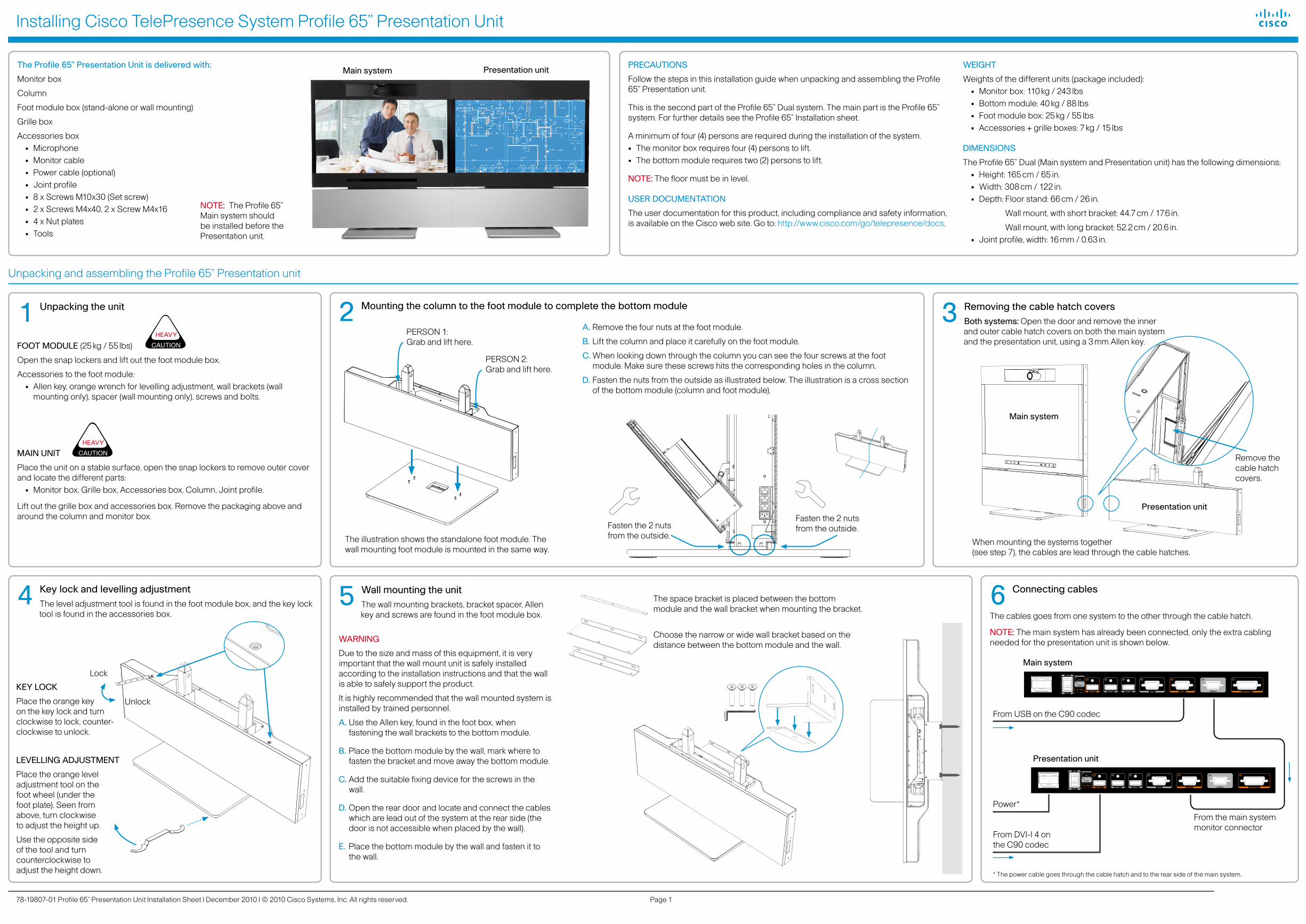
Installing Cisco TelePresence System Profile 65” Presentation Unit
Page 178-19807-01 Profile 65” Presentation Unit Installation Sheet | December 2010 | © 2010 Cisco Systems, Inc. All rights reserved.
3 Removing the cable hatch coversBoth systems: Open the door and remove the inner and outer cable hatch covers on both the main system and the presentation unit, using a 3 mm Allen key.
2 Mounting the column to the foot module to complete the bottom module
4 Key lock and levelling adjustmentThe level adjustment tool is found in the foot module box, and the key lock tool is found in the accessories box.
5 Wall mounting the unitThe wall mounting brackets, bracket spacer, Allen key and screws are found in the foot module box.
WARNING
Due to the size and mass of this equipment, it is very important that the wall mount unit is safely installed according to the installation instructions and that the wall is able to safely support the product.
It is highly recommended that the wall mounted system is installed by trained personnel.
A. Use the Allen key, found in the foot box, when fastening the wall brackets to the bottom module.
B. Place the bottom module by the wall, mark where to fasten the bracket and move away the bottom module.
C. Add the suitable fixing device for the screws in the wall.
D. Open the rear door and locate and connect the cables which are lead out of the system at the rear side (the door is not accessible when placed by the wall).
E. Place the bottom module by the wall and fasten it to the wall.
6 Connecting cables
The cables goes from one system to the other through the cable hatch.
NOTE: The main system has already been connected, only the extra cabling needed for the presentation unit is shown below.
PERSON 1: Grab and lift here.
PERSON 2: Grab and lift here.
The illustration shows the standalone foot module. The wall mounting foot module is mounted in the same way.
1 Unpacking the unit
FOOT MODULE (25 kg / 55 lbs)
Open the snap lockers and lift out the foot module box.
Accessories to the foot module:• Allen key, orange wrench for levelling adjustment, wall brackets (wall
mounting only), spacer (wall mounting only), screws and bolts.
MAIN UNIT
Place the unit on a stable surface, open the snap lockers to remove outer cover and locate the different parts:• Monitor box, Grille box, Accessories box, Column, Joint profile.
Lift out the grille box and accessories box. Remove the packaging above and around the column and monitor box.
PRECAUTIONS
Follow the steps in this installation guide when unpacking and assembling the Profile 65” Presentation unit.
This is the second part of the Profile 65” Dual system. The main part is the Profile 65” system. For further details see the Profile 65” Installation sheet.
A minimum of four (4) persons are required during the installation of the system. • The monitor box requires four (4) persons to lift.• The bottom module requires two (2) persons to lift.
NOTE: The floor must be in level.
USER DOCUMENTATION
The user documentation for this product, including compliance and safety information, is available on the Cisco web site. Go to: http://www.cisco.com/go/telepresence/docs.
WEIGHT
Weights of the different units (package included):• Monitor box: 110 kg / 243 lbs• Bottom module: 40 kg / 88 lbs• Foot module box: 25 kg / 55 lbs• Accessories + grille boxes: 7 kg / 15 lbs
DIMENSIONS
The Profile 65” Dual (Main system and Presentation unit) has the following dimensions:• Height: 165 cm / 65 in.• Width: 308 cm / 122 in.• Depth: Floor stand: 66 cm / 26 in.
Wall mount, with short bracket: 44.7 cm / 17.6 in.
Wall mount, with long bracket: 52.2 cm / 20.6 in.• Joint profile, width: 16 mm / 0.63 in.
The Profile 65” Presentation Unit is delivered with:
Monitor box
Column
Foot module box (stand-alone or wall mounting)
Grille box
Accessories box• Microphone• Monitor cable• Power cable (optional)• Joint profile• 8 x Screws M10x30 (Set screw)• 2 x Screws M4x40, 2 x Screw M4x16• 4 x Nut plates• Tools
Unpacking and assembling the Profile 65” Presentation unit
KEY LOCK
Place the orange key on the key lock and turn clockwise to lock, counter-clockwise to unlock.
LEVELLING ADJUSTMENT
Place the orange level adjustment tool on the foot wheel (under the foot plate). Seen from above, turn clockwise to adjust the height up.
Use the opposite side of the tool and turn counterclockwise to adjust the height down.
Main system Presentation unit
Fasten the 2 nuts from the outside.Fasten the 2 nuts
from the outside.When mounting the systems together (see step 7), the cables are lead through the cable hatches.
Main system
Presentation unit
A. Remove the four nuts at the foot module.
B. Lift the column and place it carefully on the foot module.
C. When looking down through the column you can see the four screws at the foot module. Make sure these screws hits the corresponding holes in the column.
D. Fasten the nuts from the outside as illustrated below. The illustration is a cross section of the bottom module (column and foot module).
Lock
Unlock
The space bracket is placed between the bottom module and the wall bracket when mounting the bracket.
Choose the narrow or wide wall bracket based on the distance between the bottom module and the wall.
Main system
B
B
Presentation unit
From USB on the C90 codec
From DVI-I 4 on the C90 codec
* The power cable goes through the cable hatch and to the rear side of the main system.
B
B
Power*
From the main system monitor connector
Remove the cable hatch covers.
NOTE: The Profile 65” Main system should be installed before the Presentation unit.
CAUTION
HEAVY
CAUTION
HEAVY

Installing Cisco TelePresence System Profile 65” Presentation Unit
Page 278-19807-01 Profile 65” Presentation Unit Installation Sheet | December 2010 | © 2010 Cisco Systems, Inc. All rights reserved.
9 Unpacking the Monitor box and mounting the monitor to the base
7 Mounting the two modules together
A. Main system: Remove the top grille and open the top cover.
B. Presentation unit: Open the top cover.
C. Both systems: Remove the uppermost screw on the monitor sides facing each other, using a 2.5 mm Allen key and a 7 mm wrench. See illustration.
D. Both systems: Remove the uppermost screw on the bottom modules, using a 3 mm Allen key and a 7 mm wrench.
E. Move the units towards each other. Leave some space for the joint profile.
F. Level and align the systems: Use the screws inside the bottom module to adjust and align the two systems. See the instructions in step 8.
G. Place the joint profile between the two systems.
H. Connect bottom modules: On the main bottom module, fasten the long M4 screw from the inside of the module through the joint profile and to the nut on the nut plate. Do the same from the inside of the presentation unit bottom module.
I. Connect the monitor: On the main monitor, fasten the short M4 screw from the inside of the monitor through the joint profile and to the nut on the nut plate.
J. If further adjustments are needed do this with the adjustments screws inside the bottom module.
8 Level and align the systems
In order to level the systems, use 4 pcs of the (a) set screw in the holes marked in the picture below for each bottom module. Note that the illustration depicts a base module as seen from above, with the door open.
Loosen nuts before adjusting the pin bolts down. When proper adjustment have been found, tighten nuts again. These are the same nuts which were mounted in step 2 D, see the previous page.
Main system
In step 7 the joint profile is mounted to the main monitor.
(In step 9 the joint profile is mounted to the second monitor.)
Uppermost screw on the monitor
The nut plates are placed inside the joint profile
Joint profile with a slot for the cables
Cable hatch
Presentation unit, base module
NOTE: Requires 4 persons and lifting straps to lift.
LIFTING STRAPS INCLUDED. The lifting straps are found in the box, together with the monitor, ready for use.
NOTE: The straps are not fixed to the monitor. Be careful when lifting the monitor so the straps do not slide during the lifting operation.
CAUTION
HEAVY AND
BULKY
REQUIRES: 4 PEOPLE TO LIFT
4 × set screw (a)
Codec
Lid
The nut plates are placed inside the joint profile
A. Carefully lift and place the monitor onto the base. B. If further adjustments are needed to align the systems, do
this with the set screws inside the base modules.C. Connect the monitor: Fasten the short M4 screw from
the inside of the monitor through the joint profile and to the nut on the nut plate.
Uppermost screw on the bottom module
11 Connect the power cable
Connect the presentation unit power cable. The cable is lead out from the rear side of the main system.
10 Mounting the grilles in front and finishing up
A. Close the top lids.
B. Snap on the top grilles.
C. Snap on the speaker grille.
D. Close the base module doors.
E. Remove the plastic foil on the monitor frame.
F. Use the supplied cloth to clean up the system.
Power cable from the Presentation unit
Ethernet cable
PC cable
Microphone cables
Power cable
Close the lids and snap on the grilles.
Close the doors and snap on the speaker grille.