Embed Size (px)
Citation preview

69964
Instruction manualpH Transmitter 2100e FF

WarrantyDefects occurring within 1 year from delivery date shall be remedied freeof charge at our plant (carriage and insurance paid by sender).
Subject to change without notice.
Return of products under warrantyPlease contact METTLER TOLEDO’s Customer Service Dept. before returninga defective device. Ship the cleaned device to the address you have beengiven. If the device has been in contact with process fluids, it must bedecontaminated/disinfected before shipment. In that case, please attach acorresponding certificate, for the health and safety of our service personnel.
Disposal (Directive 2002/96/EC of January 27, 2003)Please observe the applicable local or national regulationsconcerning the disposal of “waste electrical and electronicequipment”.
Mettler-Toledo GmbH, Process Analytics, Industrie Nord, CH-8902 Urdorf, Tel. +41 (01) 736 22 11 Fax +41 (01) 736 26 36 Subject to technical changes. Mettler-Toledo GmbH, 11/04. Printed in Germany.

3
Safety information . . . . . . . . . . . . . . . . . . . . . . . . . 7Intended use / Short description . . . . . . . . . . . . . . . . . . .9Trademarks . . . . . . . . . . . . . . . . . . . . . . . . . . . . . . . . . .10
CertificatesEC Declaration of Conformity . . . . . . . . . . . . . . . . . . . .10EC-Type-Examination Certificate . . . . . . . . . . . . . . . . . .11Device Registration . . . . . . . . . . . . . . . . . . . . . . . . . . . .17
Foundation Fieldbus technology . . . . . . . . . . . . . 18Communication model . . . . . . . . . . . . . . . . . . . . . . . . .20Commissioning and configuration via Foundation Fieldbus . . . . . . . . . . . . . . . . . . . . . . . . . . .22
Overview of the transmitter. . . . . . . . . . . . . . . . . 27Assembly. . . . . . . . . . . . . . . . . . . . . . . . . . . . . . . . . 28
Packing list . . . . . . . . . . . . . . . . . . . . . . . . . . . . . . . . . .28Mounting plan . . . . . . . . . . . . . . . . . . . . . . . . . . . . . . .29Pipe mounting, panel mounting . . . . . . . . . . . . . . . . . .30
Installation and connection . . . . . . . . . . . . . . . . . 32Information on installation . . . . . . . . . . . . . . . . . . . . . .32Terminal assignments . . . . . . . . . . . . . . . . . . . . . . . . . . .32Connecting the VP cable . . . . . . . . . . . . . . . . . . . . . . . .34VP cable assignment . . . . . . . . . . . . . . . . . . . . . . . . . . .35Wiring examples . . . . . . . . . . . . . . . . . . . . . . . . . . . . . .36
User interface and display . . . . . . . . . . . . . . . . . . 44Operation: Keypad . . . . . . . . . . . . . . . . . . . . . . . . . 46Safety functions . . . . . . . . . . . . . . . . . . . . . . . . . . . 47
Hold mode / AlarmSensocheck, Sensoface sensor monitoring / GainCheckdevice self-test / Automatic device self-test . . . . . . . . .48
Contents

4 pH Transmitter 2100e FF
Contents
Mode codes. . . . . . . . . . . . . . . . . . . . . . . . . . . . . . . 49Configuration on the device . . . . . . . . . . . . . . . . . 50
Menu structure of configuration . . . . . . . . . . . . . . . . . .51Overview of configuration steps . . . . . . . . . . . . . . . . . .52Selecting process variable / sensor . . . . . . . . . . . . . . . . .54Temperature measurement . . . . . . . . . . . . . . . . . . . . . .56Calibration mode / Calibration solution . . . . . . . . . . . . .60Alarm settings . . . . . . . . . . . . . . . . . . . . . . . . . . . . . . . .62Adjustment / Default bus address . . . . . . . . . . . . . . . . .62
Calibration on the device . . . . . . . . . . . . . . . . . . . 66pH calibration . . . . . . . . . . . . . . . . . . . . . . . . . . . . . . . .66Zero adjustment . . . . . . . . . . . . . . . . . . . . . . . . . . . . . .68Automatic calibration with Calimatic . . . . . . . . . . . . . . .70Manual calibration . . . . . . . . . . . . . . . . . . . . . . . . . . . .70Data entry of premeasured electrodes . . . . . . . . . . . . . .74Product calibration . . . . . . . . . . . . . . . . . . . . . . . . . . . .76ORP calibration . . . . . . . . . . . . . . . . . . . . . . . . . . . . . . .78Temp probe adjustment . . . . . . . . . . . . . . . . . . . . . . . . .80Calibration error messages . . . . . . . . . . . . . . . . . . . . . .81
Measurement . . . . . . . . . . . . . . . . . . . . . . . . . . . . . 82Diagnostics functions . . . . . . . . . . . . . . . . . . . . . . 83Sensoface / Sensocheck . . . . . . . . . . . . . . . . . . . . . 84
Sensoface evaluation limits . . . . . . . . . . . . . . . . . . . . . .85
Cleaning . . . . . . . . . . . . . . . . . . . . . . . . . . . . . . . . . 85
Communication Fieldbus / Device . . . . . . . . . . . . 86Resource block . . . . . . . . . . . . . . . . . . . . . . . . . . . .86-87(Block status / Write protection / Key lock / Alarm)Bus parameters . . . . . . . . . . . . . . . . . . . . . . . . . . . .88-89

5
Transducer block . . . . . . . . . . . . . . . . . . . . . . . . . . .90-91(Configuration and calibration via bus / Error messages)Bus parameters . . . . . . . . . . . . . . . . . . . . . . . . . . .92-103
Analog Input blocks . . . . . . . . . . . . . . . . . . . . . . .104-105(Operating mode / Process variables / Units / . . . . . . .104Linearization types / Diagnostics / Alarm handling . . . .105Alarm diagnostics / Bus parameters) . . . . . . . . . . . . . .107Bus parameters . . . . . . . . . . . . . . . . . . . . . . . . . .107-108
Cyclic measured value status . . . . . . . . . . . . . . . . . . . .110Operating states / Measured value status . . . . . . . . . .112Error messages / Measured value status . . . . . . . .114-117
Appendix. . . . . . . . . . . . . . . . . . . . . . . . . . . . . . . . 119Product line and accessories . . . . . . . . . . . . . . . . . . . .119Specifications . . . . . . . . . . . . . . . . . . . . . . . . . . . . . . .120Patent List (Intellectual Property Rights) . . . . . . . . . . . .125Division 2 wiring . . . . . . . . . . . . . . . . . . . . . . . . . . . .124Buffer tables . . . . . . . . . . . . . . . . . . . . . . . . . . . . . . . .127FM Control Drawing . . . . . . . . . . . . . . . . . . . . . . . . . .134
Glossary . . . . . . . . . . . . . . . . . . . . . . . . . . . . . . . . 137Index . . . . . . . . . . . . . . . . . . . . . . . . . . . . . . . . . . . 142

6 pH Transmitter 2100e FF

7
Be sure to read and observe the followinginstructions!
The device has been manufactured using state of the art tech-nology and it complies with applicable safety regulations.When operating the device, certain conditions may neverthe-less lead to danger for the operator or damage to the device.
Caution!Commissioning may only be carried out by trained experts.Whenever it is likely that protection has been impaired, thedevice shall be made inoperative and secured against unintend-ed operation.
The protection is likely to be impaired if, for example:• the device shows visible damage• the device fails to perform the intended measurements• after prolonged storage at temperatures above 70 °C• after severe transport stresses
Before recommissioning the device, a professional routine testin accordance with EN 61010-1 must be performed. This testshould be carried out by the manufacturer.
Caution!Before commissioning it must be proved that the device maybe connected with other equipment, such as coupling elementsand cables.
Safety information

8 pH Transmitter 2100e FF
Safety precautions for installation
• The stipulations of EN 60079-10 / EN 60079-14 must be observed during commissioning.
• The pH Transmitter 2100e FF is approved for installation in ATEX, FM Zone 1 with measurement in Zone 0, and FM Class I Div 1.
Connection to supply and coupling elements• The pH Transmitter 2100e FF may only be connected to
explosion-proof power supply and coupling elements (for input ratings refer to annex of Type Examination Certificate).
Before commissioning it must be proved that the intrinsic safety is maintained when connecting the device to other equipment, such as supply elements and cables.
Terminals: suitable for single wires / flexible leads up to 2.5 mm2 (AWG 14)
Cleaning in a hazardous locationIn hazardous locations the device may only be cleaned with adamp cloth to prevent electrostatic discharge.

9
Intended use / Short description
The pH Transmitter 2100e FF is an analyzing device with digitalcommunication via Foundation Fieldbus (FF). It is used for simul-taneous pH/mV, ORP, and temperature measurement in biotech-nology, chemical and pharmaceutical industry, as well as in thefield of industry, environment, food processing, pulp and paper,and waste-water treatment. 3 measured values can be cyclically transmitted at the same time(pH, ORP, temperature, glass impedance, reference impedance,slope, asymmetry). The bus address is automatically assigned by the control system,but can also be adjusted on the device. The rugged moldedenclosure can be fixed into a control panel or mounted on a wallor at a post. The protective hood provides additional protection against directweather exposure and mechanical damage.The device can be easily replaced and it accepts commerciallyavailable electrodes with a nominal zero point at pH 7 and ISFETsensors.
• The pH Transmitter 2100e FF is an intrinsically safe equipment for operation in the following locations: ATEX, FM Zone 1 with measurement in Zone 0, and FM Class I Div 1. Power is supplied (intrinsically safe) via the fieldbus.

10 pH Transmitter 2100e FF
Trademarks
The following names are registered trademarks. For practicalreasons they are shown without trademark symbol in thismanual:GainCheckSensofaceSensocheckCalimatic
InPro® is a registered trademark of Mettler-Toledo.

11
ECDeclaration of Conformity

12 pH Transmitter 2100e FF
EC-Type-Examination Certificate

13

14 pH Transmitter 2100e FF

15

16 pH Transmitter 2100e FF
EC-Type-Examination Certificate1st supplement

17
Fieldbus Foundation:Device registration

18 pH Transmitter 2100e FF
Foundation Fieldbus (FF) technologyGeneral
Foundation Fieldbus (FF) is a digital communication system thatconnects different field devices over a common cable and inte-grates them into a control system. Its application range covers manufacturing, process, andbuilding automation. As fieldbus standard according to EN 61158-2 (IEC 1158-2) theFoundation Fieldbus ensures the communication of differentdevices over one bus line.
Basic properties
The “Data Link Layer” of the Fieldbus Foundation protocoldefines 3 device types:
The Active Link Master plans all activities as “Link ActiveScheduler” (LAS). It controls the complete data traffic on thebus. Several Link Masters on one bus increase safety, but onlyone is active at a time.
Basic devices are peripheral devices such as valves, drives,transmitters, or analyzers. They can react acyclically to servic-ing, configuration and diagnostic tasks of the master. The Link Master cyclically reads the measurement data withstatus.
Bridges can connect a network from different bus systems.
Bus communicationFoundation Fieldbus (FF) permits cyclic and acyclic services:
19
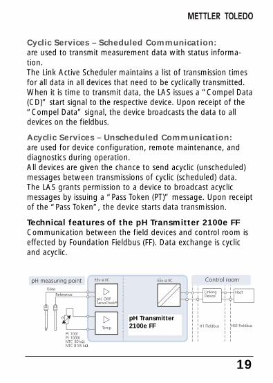
Cyclic Services – Scheduled Communication:are used to transmit measurement data with status informa-tion.The Link Active Scheduler maintains a list of transmission timesfor all data in all devices that need to be cyclically transmitted.When it is time to transmit data, the LAS issues a “Compel Data(CD)” start signal to the respective device. Upon receipt of the“Compel Data” signal, the device broadcasts the data to alldevices on the fieldbus.
Acyclic Services – Unscheduled Communication:are used for device configuration, remote maintenance, anddiagnostics during operation. All devices are given the chance to send acyclic (unscheduled)messages between transmissions of cyclic (scheduled) data. The LAS grants permission to a device to broadcast acyclicmessages by issuing a “Pass Token (PT)” message. Upon receiptof the “Pass Token”, the device starts data transmission.
Technical features of the pH Transmitter 2100e FFCommunication between the field devices and control room iseffected by Foundation Fieldbus (FF). Data exchange is cyclicand acyclic.
pH Transmitter2100e FF

pH
ORPTemperature
R meas *
R reference **
Slope
Asymmetry potential
20 pH Transmitter 2100e FF
Resource Block
Tran
sdu
cer
Blo
ck
Fiel
db
us
Temp
pH Transmitter 2100e FF
RTD
The device performance is described by function blocks accord-ing to the “Fieldbus Specification” for process control devices.
chan
nel
AI Function Block 1
pH
ORPTemperature
Slope
Asymmetry potential
chan
nel
AI Function Block 3
pH
ORPTemperature
Slope
Asymmetry potential
chan
nel
AI Function Block 2pH/ORP
Communication model
* R meas = glass impedance ** R reference = reference impedance
R meas *
R reference **
R meas *
R reference **

21
Function blocks
All variables and parameters of the transmitter are assigned toblocks. The pH Transmitter 2100e FF is equipped with the fol-lowing blocks:
Standard Resource Block (RB) describes the transmittercharacteristics (manufacturer, device name, operating status,global status).
Standard Analog Input Block (AI)Three Analog Input Function Blocks provide for cyclic transmis-sion of measured values (currently measured value with status,alarm limits, freely selectable process variable).
Transducer Block (TB) with calibration possibilityprovides for acyclic data transmission. Calibration, configuration, and maintenance commands com-ing from the control station are processed in the TransducerBlock.The sensor signal is first preprocessed in the Transducer Block.From here, the measured value is sent to the Analog InputBlocks where it can be further processed (limit values, scaling).
22 pH Transmitter 2100e FF
Commissioning and configuration viaFoundation Fieldbus
Commissioning on the Foundation FieldbusDifferent configuration tools from different manufacturers areavailable. They can be used to configure the device and theFoundation Bus.
Note:Be sure to observe the operating instructions and the menu guidance of the control system or the configuration tool duringinstallation and configuration via the control system.
Installing the DD (Device Description):During initial installation the device description (*.sym, *.ffo)must be installed in the control system.For network projecting, you require the CFF file (Common File Format).
These files can be obtained from:
• the included CD• the www.mtpro.com/transmitters website• Foundation Fieldbus: www.fieldbus.org.

23
Identifying the transmitterThere are several possibilities to identify a FF transmitter in thenetwork. The most important one is the “Device Identifier” orDEV_ID. It consists of the manufacturer ID, device type, andserial number XXXXXXX.
The DEVICE_ID is: 4652550834 V2_01__XXXXXXX00
Manufacturer ID Mettler-Toledo: MANUFAC_ID = 0x465255
Device ID pH Transmitter 2100e FF: DEV_TYPE = 2100
Initial commissioning
1. Supply the device with power (see “Installation and wiring”, Pg 32).
2. Open the configuration program of the control system. 3. Load DD and CFF file.
After the first connection establishment, the device answersas follows:
MT 2100-FF V2_01__XXXXXXX00- ID= 4652550834 V2_01__XXXXXXX00
4. Assign the desired name to the field device. (PD_TAG)
Setting the Resource Block (RB) parameters
5. Make sure that the WRITE_LOCK parameter is set to “NOT LOCKED”.
6. Set the MODE_BLK. TARGET to Auto.
24 pH Transmitter 2100e FF
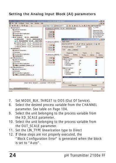
Setting the Analog Input Block (AI) parameters
7. Set MODE_BLK. TARGET to OOS (Out Of Service).8. Select the desired process variable from the CHANNEL
parameter. See table on Page 104.9. Select the unit belonging to the process variable from
the XD_SCALE parameter.10. Select the unit belonging to the process variable from
the OUT_SCALE parameter.11. Set the LIN_TYPE linearization type to Direct12. If these steps are not properly executed, the
“Block Configuration Error” is generated when the block is set to “Auto”.

25
This step is mandatory since otherwise the target mode of theAnalog Input Block cannot be set to “Auto”.Using the NI-FBUS Configurator from National Instruments, forexample, you can graphically connect the function blocks andthen load the system configuration in the device.
13. Download all data and parameters to the field device.14. Set the target modes of all Analog Input Blocks to
“Auto”.
System configuration

26 pH Transmitter 2100e FF

27
Overview of the transmitter
1
2
4
5
6
7
8
15
pH / mV input
FF-H1EN 61158-2
Glasselectrode
Referenceelectrode
Auxiliaryelectrode
RTD
RTD
A
B
Tempinput
EEx ia IIC
Not connected
Power supply(ISFET)
– 3 V
GND
+3 V
17
18
19
14
16 (Equipotentialbonding)
FF-H1EN 61158-2IEC 1158-2

28 pH Transmitter 2100e FF
Assembly
11
10
9
8
7 6 5 4
1
2
3
Fig.: Assembling the enclosure
6 Sealing inserts (1 piece)7 Rubber reducer (1 piece)8 Cable glands (3 pieces)9 Filler plugs (3 pieces)10 Hexagon nuts (5 pieces)11 Sealing plugs (2 pieces):
for sealing in case of wall mounting
1 Jumper (2 piece)2 Washer (1 piece), for conduit
mounting: place washer between enclosure and nut
3 Cable ties (3 pieces)4 Hinge pin (1 piece), insertable from
either side5 Enclosure screws (4 pieces)
Packing listCheck the shipment for transport damage and completeness.The package should contain:• Front unit • Instruction manual• Lower case • Specific test report• Bag containing small parts • CD with Device Description
* .sym, * .ffoCommon File Format CFF-File

29
Mounting plan
144
144
15 42
84
8032
21
43
105
27
726,
2
1 2
3
4
1 Cable gland (3 pieces)2 Breakthroughs for cable gland
or conduit 1/2”,ø 21.5 mm (2 breakthroughs)Conduits not included!
3 Breakthroughs for pipe mounting (4 breakthroughs)
4 Breakthroughs for wall mounting (2 breakthroughs)
Fig.: Mounting plan

30 pH Transmitter 2100e FF
40 60132
1
2
34
5
Fig.: Pipe-mount kit
1 Protective hood (if required)2 Hose clamps with worm gear drive to DIN 3017 (2 pieces)3 Pipe-mount plate (1 piece)4 For vertical or horizontal posts or pipes5 Self-tapping screws (4 pieces)
1
132165
173
1
Fig.: Protective hood for wall and pipe mounting
Pipe mounting, panel mounting

31
1
2
3
45
max. 2578 27
1...22
1 Screws (4 pieces)2 Gasket (1 piece)3 Panel4 Span pieces (4 pieces)5 Threaded sleeves (4 pieces)
Fig.: Panel-mount kit
Panel cutout 138 x 138 mm(DIN 43700)

32 pH Transmitter 2100e FF
Installation and connection
Terminal assignments
Fig.: Terminal assignments pH Transmitter 2100e FF
• The pH Transmitter 2100e FF may only be connected to explosion-proof power supply and coupling elements (for input ratings refer to annex of Type Examination Certificate). Before commissioning it must be proved that the device may be con-nected to other equipment, such as supply elements and cables.
• Installation may only be carried out by trained experts in accordance with this instruction manual and as per applicable local and national codes. Be sure to observe the technical specifications and input ratings during installation.
• Be sure to observe the IEC 60079-27 “Fieldbus Intrinsically Safe Concept (FISCO)” and the “Fieldbus Non-Incendive Concept FNICO)”
• Be sure not to notch the conductor when stripping the insulation.• When commissioning, a complete configuration must be
carried out by the system administrator.For easy installation, the terminal strips are of a plug-in design. Terminals: suitable for single wires / flexible leads up to 2.5 mm2
(AWG 14). A special twisted and shielded two-wire cable (e.g.Siemens) is used as bus cable.
Division 2 wiring: Refer to page
Control Drawing: Refer to page
124.
134.

33
1 Recommended strippinglengths for multi-core cables
2 Recommended strippinglength for coaxial cable
3 Pulling out the terminalsusing a screwdriver(also see 7)
4 Cable laying in the device
5 Connecting lines for Fieldbus
6 Cover for electrode andtemperature probe terminals
7 Area for placing the screw-driver to pull out the terminals
8 Connecting terminals for Fieldbus
Fig.: Information on installation, rear side of device
1 2 3
4
5
7
6
7m
m
280
mm
13m
m
7m
m
8
5

34 pH Transmitter 2100e FF
Connecting the sensor to the VP cable
Connecting the VP cable
Note:Cable lengths > 20 m can worsen the responseduring pH measurement.Be sure to observe the sensor instruction manual.

35
VP cable assignment
A transparent Cathode
B red Ref. electrode
C gray T3
D blue Aux. electrode
E white T1
F green T2
S green/yellow Outer shield
T1/T2= Temperature probe for 2-wire connectionT1 = Additional connection for temperature probe
(3-wire connection)
C = 220 nF

36 pH Transmitter 2100e FF
pH wiring examples
171819
+3
V
-3V
Cable
CombinationpH electrode
Example 1:• pH measurement with monitoring of glass electrode
(connection: VP)ye
llow
/gre
en
(ext
erna
lshi
eld)
whi
te
gree
n
tran
spar
ent
(cor
e)
Jumperterminals 4 + 5 !
red
(shi
eld)

171819
+3
V
-3V
37
Cable
Equi-potentialbondingelectrode
Example 2:• pH measurement with monitoring of glass and reference electrode/
simultaneous ORP measurement (connection: VP)• pH/ORP values can be simultaneously transmitted over the Fieldbus.
Cable
tran
spar
ent
(cor
e)
red
(shi
eld)
whi
te
gree
n
yello
w/g
reen
(ext
erna
lshi
eld)
Combi-nationpHelec-trode
core
+sh
ield

38 pH Transmitter 2100e FF
pH wiring examples
171819
+3
V
-3V
Cable
e.g.InPro3200SG(Mettler-Toledo)
Example 3:• pH measurement with monitoring of glass and reference electrode /
simultaneous ORP measurement (connection: VP)• pH/ORP values can be simultaneously transmitted over the Fieldbus.
yello
w/g
reen
(ext
erna
lshi
eld)
whi
te
gree
n
blue
tran
spar
ent
(cor
e)
red
(shi
eld)

39
171819
+3
V
-3V
Temperatureprobe
CombinationpHelectrode
Example 4:• pH measurement with monitoring of glass electrode
Jumperterminals 4 + 5 !
40 pH Transmitter 2100e FF
171819
+3
V
-3V
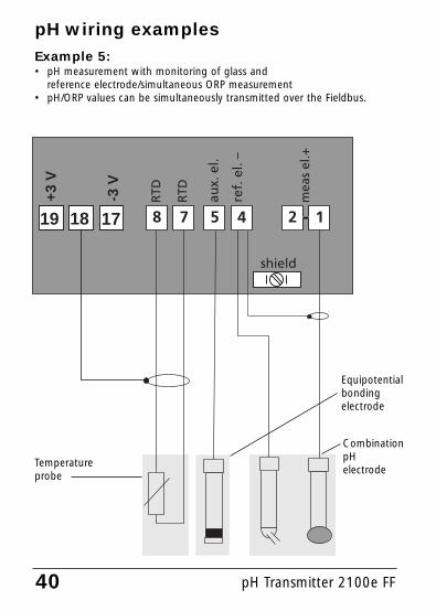
pH wiring examplesExample 5:• pH measurement with monitoring of glass and
reference electrode/simultaneous ORP measurement• pH/ORP values can be simultaneously transmitted over the Fieldbus.
Temperatureprobe
CombinationpH electrode
Equipotential bonding electrode

41
Example 6:• pH measurement with ISFET sensor• Be sure that “ISFET” is set in the configuration, see Pg 55.
gray
gree
n
yello
w
yello
w/g
reen
brow
n
whi
te
pink
Jumperterminals4 + 5 !
InPro 3300ISFET sensor

ORP wiring example
171819
+3
V
-3V
Cable
ORP electrode
Example 7:• ORP measurement with Sensocheck for reference electrode
Temperatureprobe
Jumperterminals 2 + 5 !
42 pH Transmitter 2100e FF

43

44 pH Transmitter 2100e FF
User interface and display
1 Display2 Mode indicators (no keys),
from left to right:- Measuring mode- Calibration mode- Alarm- Foundation Fieldbus communication- Configuration mode
3 Keypad4 Coding5 Rating plate6 Model designation7 Alarm LED
User interface

45
1 2 3 4 5 6 7 8 9 10
11
12
13
1617
20
18
19
15 14
1 Mode code entry2 Display of measured variable*3 Temperature4 Not connected5 Limit values6 Alarm7 Sensocheck8 Calibration9 Interval/response time10 Not connected11 Measurement symbols12 Proceed with enter13 Bar for identifying the
device status, above mode indicators from left to right:- Measuring mode- Calibration mode- Alarm- Foundation Fieldbus communication- Configuration mode
14 Lower display15 Manual temp specification16 Hold mode active17 Waiting time running18 Electrode data19 Main display20 Sensoface
* Not in use
Display

Operation: Keypad
conf
Start, end calibration
Start configuration
Select digit position(selected position flashes)
Edit digit
• Calibration: Continue in program sequence
• Configuration: Confirm entries,next configuration step
• End the Hold mode
Cal Info, display of asymmetry potentialand slope
Error Info: Display of last error message
Start GainCheck device self-test+
Abort configuration, calibration, then Holdmode is activated.
46 pH Transmitter 2100e FF

47
Safety functions
Hold mode
Display:
The Hold mode is a safety state during configuration and cali-bration. In Hold mode the last valid value (last usable value) istransmitted. Measured value status = uncertain : Last_usable_valueIf the calibration or configuration mode is exited, the transmit-ter remains in the Hold mode for safety reasons. This prevents undesirable reactions of the connected peripher-als due to incorrect configuration or calibration. The measuredvalue and “HOLD” are displayed alternately. The transmitteronly returns to measuring mode after enter is pressed and20 seconds have passed.
AlarmDuring an error message the alarm LED flashes.The alarm response time is permanently set to 10 sec.The alarm LED on the front panel can be configured as follows:HOLD off: Alarm: LED flashingHOLD on: Alarm: LED on. HOLD: LED flashing. (see Pg 63)
Configuration mode is also exited automatically 20 minutesafter the last keystroke (timeout). The transmitter returns tomeasuring mode.
Timeout is not active during calibration.
For alarm handling via Foundation Fieldbus, see Pg 105

Safety functions
Sensocheck, Sensoface sensor monitoringSensocheck continuously monitors the sensor and lines.Sensocheck can be switched off (Configuration, Pg 63).
Sensoface provides information on the electrode condi-tion. The asymmetry potential (zero), slope andresponse time during calibration are evaluated. Thethree Sensoface indicators provide the user with infor-mation about wear and required maintenance of theelectrode.
GainCheck device self testA display test is carried out, the software version is displayedand the memory and measured value transfer are checked.
Start GainCheck device self-test:
Automatic device self-testThe automatic device self-test checks the memory and meas-ured-value transfer. It runs automatically in the background atfixed intervals.
+
48 pH Transmitter 2100e FF

49
Mode codesThe mode codes allow fast access to the functions
Calibration
Key + Code Description
Cal InfoDisplay of zero and slope
0000
1001
Product calibration Adjusting the asymmetry potential (zero)
1105
1009
Configuration
Error InfoDisplay last error and erase
0000
Configuration
Sensor monitorDisplay of uncorrected electrode potential
1200
2222
Key + Code Description
pH calibrationAdjusting the zero/slope (sensor)
1100
Zero adjustment (ISFET)Adjusting the nominal zero (ISFET sensor only)
83
68
76
80
83
55
83
70
Page
Page
Temp probe adjustment1015
78
conf
conf
conf
ORP calibrationAdjusting the oxidation-reduction potential (zero)

50 pH Transmitter 2100e FF
Configuration on the deviceConfiguration on the device is mainly used for setting displayparameters.
Activate with meas + cal
Enter mode code “1200”Edit parameter with 4 and 5,confirm/continue with enter.(End with meas, then enter.)
The last valid value (last usablevalue) is transmitted. Measuredvalue status = uncertain :Last_usable_value.Sensoface is off, “Configuration”mode indicator is on.
Red LED flashes when “HOLD ON”has been set.
Activate
Hold
Input errors The configuration parameters arechecked during the input. In the caseof an incorrect input ”Err” is dis-played for approx. 3 sec. The incor-rect parameters cannot be stored.Input must be repeated.
End End with meas. The measured valueand Hold are displayed alternately“enter” flashes. (HOLD symbol is on,“hourglass” flashes, Sensoface isactive).
Press enter to end the Hold mode.The measured value is displayed. Hold remains on for 20 sec (measuredvalue status = uncertain:Last_usable_value.
HOLD icon
conf
During configu-ration the trans-mitter remainsin the Holdmode.

51
Code
Menu structure of configuration
The configuration steps are optically organized in menu groups:• Process variable /
electrode type selection (code: In.)• Temperature compensation (code: tc.)• Calibration mode (code: CA.)• Alarm settings (code: AL.)• Input of bus address (code: FF.)
Pressing the enter key accesses the next configuration step. The values areedited using the arrow keys. Pressing enter confirms/stores the settingsand opens the next configuration step.After the last configuration step the menu starts once more with the wel-come text and the first step is opened again. Return to measurement: Press meas.
Selectconfiguration step
Display(3 sec)
Select variable/unit
Select electrode type
Select °C/°F
Select temperature probe
Temp during measurement
Temp during calibration
Enter TC process medium
Select calibration mode / solution
Cal timer interval
Select Sensocheck
LED in Hold mode
Enter default bus address
In.UnIT
In.SnSR
tc.UnIT
tc.rTD
tc.MEAS
tc.CAL
tc.LIN
CA.SOL
CA.timE
AL.SnSo
AL.LED
FF.ADR
Code: AL.LED
Configuration steps
52 pH Transmitter 2100e FF
pH/ORP
GLAS EL / FEt EL
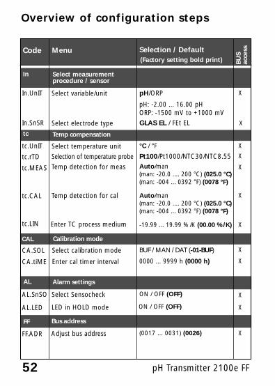
tc.UnIT Select temperature unit °C / °F
Pt100/Pt1000/NTC30/NTC8.55
Temp detection for meas Auto/man (man: -20.0 .... 200 °C) (025.0 °C)(man: -004 ... 0392 °F) (0078 °F)
Temp detection for cal
Enter TC process medium -19.99 ... 19.99 %/K (00.00 %/K)
tc Temp compensation
CAL Calibration mode
CA.SOL Select calibration mode BUF / MAN / DAT (-01-BUF)
Enter cal timer interval 0000 ... 9999 h (0000 h)
MenuCode
In
In.UnIT Select variable/unit
Select electrode type
Selection / Default
AL Alarm settings
AL.SnSO Select Sensocheck ON / OFF (OFF)
LED in HOLD mode ON / OFF (OFF)
(Factory setting bold print)
Auto/man (man: -20.0 .... 200 °C) (025.0 °C)(man: -004 ... 0392 °F) (0078 °F)
In.SnSR
tc.rTD
tc.MEAS
tc.CAL
tc.LIN
CA.tiME
AL.LED
Overview of configuration steps
FF Bus address
Adjust bus address (0017 ... 0031) (0026)FF.ADR
pH: -2.00 ... 16.00 pHORP: -1500 mV to +1000 mV
BU
Sac
cess
X
X
X
X
X
X
X
X
X
X
X
X
Select measurement procedure / sensor
Selection of temperature probe

53
Code Parameter Setting
In.UnIT pH/ORP unit ____________ ____________
In.SnSR Electrode type ____________ ____________
tc.UnIT Unit °C / °F ____________ ____________
tc.rTD Temp probe ____________ ____________
tc.MEAS Measuring temp ____________ ____________
tc.CAL Calibration temp ____________ ____________
tc.LIN TC process medium ____________ ____________
CA.SOL Calibration solution ____________ ____________
CA.tiME Calibration interval ____________ ____________
AL.SnSO Sensocheck ____________ ____________
AL.LED LED Hold ____________ ____________
FF.ADR Bus address ____________ ____________
Individual settings

54 pH Transmitter 2100e FF
Configuration on the device
Select variable/unit. Select electrode type
2
Welcome (3 sec)
1
3
conf
5
4Select variable/unit
Select electrode type
Select °C / °F
Select temperature probe
Temp during measurement
Temp during calibration
Enter TC process medium
Select calibration mode / solution
Cal timer interval
Select Sensocheck
LED in Hold mode
Enter default bus address
In.UnIT
In.SnSR
tc.UnIT
tc.rTD
tc.MEAS
tc.CAL
tc.LIN
CA.SOL
CA.timE
AL.SnSo
AL.LED
FF.ADR
1. Simultaneously press meas + cal.2. Enter code 1200, then press enter.
The device goes to Hold mode.3. “ConF” is displayed for 3 sec.
Then the Select variable/unitmenu opens. Edit with arrow keys (see Pg 55).Confirm (and proceed) with enter.
4. Pressing enter opens the next menu step.
5. End: Press meas, then enter

Note: Characters represented in gray are flashing and can be edited.
55
Code Display Action Choices
In. Select configuration(Press meas + cal.)
The device is in HOLD mode(HOLD icon is active, red LED flash-es when “HOLD ON” has beenset.).
Select variable/unit to be displayedpH / ORPSelect with arrow key 4Proceed with enter
pH/ORP(pH: -2.00... +16.00 /ORP: -1500 mV...+1000mV)
Select electrode type:• Glass electrode• ISFET electrodeSelect with 4 arrow key Proceed with enter
Glass(FEt EL)
After correct input awelcome text (CONF) isdisplayed for approx. 3 sec
Enter mode code “1200”(Select position using arrow key 4and edit number using 5 key.When the display reads “1200”,press enter to confirm.)

pH Transmitter 2100e FF
Configuration on the device
Select temperature unit and probe.
56
1. Press meas + cal.2. Enter code 1200, then press enter.
The device goes to Hold mode.3. “ConF” is displayed for 3 sec.
Press enter to open Select temperature unit and probe menu step. Edit with arrow keys (see Pg 57).Confirm (and proceed) with enter.
4. Pressing enter opens the next menu step.
5. End: Press meas, then enter
2
Welcome (3 sec)
1
3
conf
5
4Select variable/unit
Select electrode type
Select °C/°F
Select temperature probe
Temp during measurement
Temp during calibration
Enter TC process medium
Select calibration mode / solution
Cal timer interval
Select Sensocheck
LED in Hold mode
Enter default bus address
In.UnIT
In.SnSR
tc.UnIT
tc.rTD
tc.MEAS
tc.CAL
tc.LIN
CA.SOL
CA.timE
AL.SnSo
AL.LED
FF.ADR

57
°C(°F)
Code Display Action Choices
tc.
Select temperature probeSelect with 4 arrow key.Proceed with enter
Pt100(Pt1000,NTC30, NTC8.55)
Specify temperature unitSelect with 4 arrow key.Proceed with enter

58 pH Transmitter 2100e FF
Configuration on the deviceTemperature compensationTemp detection for meas/cal, TC process medium
1. Simultaneously press meas + cal.2. Enter code 1200, then press enter.
The device goes to Hold mode.3. “ConF” is displayed for 3 sec. Press enter
to open Select temp detection for measurement menu step. Edit with arrow keys (see Pg 59). Confirm (and proceed) with enter.
4. Pressing enter opens the next menu step.
5. End: Press meas, then enter
2
Welcome (3 sec)
1
3
conf
5
4Select variable/unit
Select electrode type
Select °C/°F
Select temperature probe
Temp during measurement
Temp during calibration
Enter TC process medium
Select calibration mode / solution
Cal timer interval
Select Sensocheck
LED in Hold mode
Enter default bus address
In.UnIT
In.SnSR
tc.UnIT
tc.rTD
tc.MEAS
tc.CAL
tc.LIN
CA.SOL
CA.timE
AL.SnSo
AL.LED
FF.ADR
59
AUT(MAN)
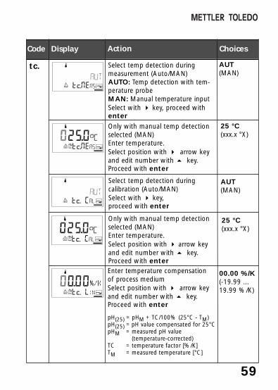
Code Display Action Choices
tc. Select temp detection duringmeasurement (Auto/MAN)AUTO: Temp detection with tem-perature probeMAN: Manual temperature inputSelect with 4 key, proceed withenter
Only with manual temp detectionselected (MAN)Enter temperature.Select position with 4 arrow keyand edit number with 5 key.Proceed with enter
25 °C(xxx.x °X)
Select temp detection duringcalibration (Auto/MAN)Select with 4 key, proceed with enter
AUT(MAN)
Enter temperature compensation of process mediumSelect position with 4 arrow keyand edit number with 5 key.Proceed with enter
pH(25) = pHM + TC/100% (25°C - TM)pH(25) = pH value compensated for 25°CpHM = measured pH value
(temperature-corrected)TC = temperature factor [%/K]TM = measured temperature [°C]
00.00 %/K(-19.99 ...19.99 %/K)
25 °C(xxx.x °X)
Only with manual temp detectionselected (MAN)Enter temperature.Select position with 4 arrow keyand edit number with 5 key.Proceed with enter

60 pH Transmitter 2100e FF
Configuration on the deviceSelect calibration mode and solution
1. Simultaneously press meas + cal.2. Enter code 1200, then press enter.
The device goes to Hold mode.3. “ConF” is displayed for 3 sec. Press enter
to open Select calibration mode / solution menu step. Edit with arrow keys (see Pg 61). Confirm (and proceed) with enter.
4. Pressing enter opens the next menu step.5. End: Press meas, then enter
2
Welcome (3 sec)
1
3
conf
5
4Select variable/unit
Select electrode type
Select °C/°F
Select temperature probe
Temp during measurement
Temp during calibration
Enter TC process medium
Select cal mode / solution
Cal timer interval
Select Sensocheck
LED in Hold mode
Enter default bus address
In.UnIT
In.SnSR
tc.UnIT
tc.rTD
tc.MEAS
tc.CAL
tc.LIN
CA.SOL
CA.timE
AL.SnSo
AL.LED
FF.ADR
61
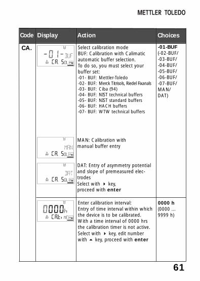
-01-BUF(-02-BUF/-03-BUF/-04-BUF/-05-BUF/-06-BUF/-07-BUF/MAN/DAT)
Code Display Action Choices
CA. Select calibration modeBUF: Calibration with Calimaticautomatic buffer selection. To do so, you must select yourbuffer set: -01- BUF: Mettler-Toledo-02- BUF: Merck Titrisols, Riedel Fixanals-03- BUF: Ciba (94)-04- BUF: NIST technical buffers-05- BUF: NIST standard buffers-06- BUF: HACH buffers-07- BUF: WTW technical buffers
Enter calibration interval:Entry of time interval within whichthe device is to be calibrated.With a time interval of 0000 hrsthe calibration timer is not active.Select with 4 key, edit numberwith 5 key, proceed with enter
0000 h(0000 ...9999 h)
MAN: Calibration with manual buffer entry
DAT: Entry of asymmetry potentialand slope of premeasured elec-trodes Select with 4 key,proceed with enter

62 pH Transmitter 2100e FF
Configuration on the deviceAlarm settings
1. Simultaneously press meas + cal.2. Enter code 1200, then press enter.
The device goes to Hold mode.3. “ConF” is displayed for 3 sec. Press enter
to open Alarm settings menu step. Edit with arrow keys (see Pg 63).Confirm (and proceed) with enter.
4. Pressing enter opens the next menu step.
5. End: Press meas, then enter
2
1
3
conf
5
4Select variable/unit
Select electrode type
Select °C/°F
Select temperature probe
Temp during measurement
Temp during calibration
Enter TC process medium
Select calibration mode / solution
Cal timer interval
Select Sensocheck
LED in Hold mode
Enter default bus address
In.UnIT
In.SnSR
tc.UnIT
tc.rTD
tc.MEAS
tc.CAL
tc.LIN
CA.SOL
CA.timE
AL.SnSo
AL.LED
FF.ADR

63
Code Display Action Choices
ON / OFFAL. Select Sensocheck(continuous monitoring of glass andreference electrode)Select with 4key, proceed withenter
LED in Hold modeSelect with 4key, proceed withenter
ON / OFF
Parameter setting Alarm HOLD
ON on flashes
OFF flashes off
LED state:

64 pH Transmitter 2100e FF
2
Welcome (3 sec)
1
3
conf
5
Configuration on the deviceAdjustment / Default bus address
1. Simultaneously press meas + cal.2. Enter code 1200, then press enter.
The device goes to Hold mode.3. “ConF” is displayed for 3 sec.
Press enter to select Adjustment / Default bus addressEdit with arrow keys (see Pg 65).Confirm (and proceed) with enter.
4. Pressing enter opens the next menu step.
5. End: Press meas, then enter
Select variable/unit
Select electrode type
Select °C/°F
Select temperature probe
Temp during measurement
Temp during calibration
Enter TC process medium
Select calibration mode / solution
Cal timer interval
Select Sensocheck
LED in Hold mode
Enter default bus address
In.UnIT
In.SnSR
tc.UnIT
tc.rTD
tc.MEAS
tc.CAL
tc.LIN
CA.SOL
CA.timE
AL.SnSo
AL.LED
FF.ADR
4

65
0026(0017...0036)
Code Display Action Choices
FF. Only when there is no bus connec-tion:The bus address can be manuallyadjusted from 0017 ... 0036.Select with4 key, edit number with5 key, proceed with enter.When the bus address has beenchanged, the device automaticallyrestarts to re-initialize the busparameters.
Note: When the bus address has been changed, the bus configuration is auto-matically reset. All bus parameters are set to their default values. All individ-ual settings have to be entered once more. The configuration must bereloaded into the device.
Adjusting a new default bus address
The Fieldbus Foundation automatically assigns an address. Therefore it is notrequired to manually adjust the bus address. If the bus address has been changed, the bus configuration is reset to thedefault values during device restart. All bus parameters are set to theirdefault values.

pH Transmitter 2100e FF
Calibration on the deviceCalibration adjusts the device to the electrode.
Activate with cal
The last valid value (last usable value)is transmitted. Measured value status= uncertain : Last_usable_value.Sensoface is off, “Calibration” modeindicator is on. Red LED flashes when “HOLD ON”has been set.
Activate
Hold
Input errors The calibration parameters arechecked during the input. In the caseof an incorrect input ”Err” is dis-played for approx. 3 sec. The incor-rect parameters cannot be stored.Input must be repeated.
End End with cal.The measured value and Hold are dis-played alternately, “enter” flashes. Press enter to end the Hold mode. Themeasured value is displayed. Holdremains on for 20 sec (measuredvalue status = uncertain:Last_usable_value. (HOLD icon is on,“hourglass” flashes).
HOLD icon
66
During calibra-tion the deviceremains in theHold mode.
Enter mode code:• 1001 zero adjustment (ISFET) • 1100 for pH• 1109 for ORP• 1105 product calibration (pH/ORP) • 1015 temp probe adjustmentSelect with 4 key, edit number with 5key, proceed with enter key(End with cal, then enter.)

67
pH calibrationCalibration is used to adapt the device to the individual elec-trode characteristics, namely asymmetry potential and slope.Calibration can be performed with Calimatic automatic bufferrecognition, with manual buffer input, by entering premea-sured electrode data, or by sampling the product. When using ISFET electrodes, you must adjust the zero pointfirst. Then you can conduct either a one or a two-point calibra-tion.Caution• All calibration procedures must be performed by trained
personnel. Incorrectly set parameters may go unnoticed, but change the measuring properties.
• The response time of the electrode and temperature probe is considerably reduced if the electrode is first moved about in the buffer solution and then held still.
• The device can only operate properly when the buffer solutions used correspond to the configured set. Other buffer solutions, even those with the same nominal values, may demonstrate a different temperature behavior. This leads to measurement errors.
When using ISFET electrodes or electrodes with azero point other than pH 7 the nominal zero point mustbe adjusted each time a new electrode is connected. This isimportant if you want to obtain reliable Sensoface messages.The Sensoface messages issued during all further calibrationsare based on this basic calibration.

68 pH Transmitter 2100e FF
Display Action Remark
If the zero offset ofthe electrode is toolarge (> ± 200 mV),the CAL ERR errormessage is generat-ed. In that case theelectrode cannot becalibrated.
Zero adjustment (ISFET)Allows use of pH electrodes with differing nominal zero, e.g.ISFET sensors.
Press cal key, enter mode code 1001Select with 4 key, edit numberwith 5 key, proceed with enter
Immerse electrode in a pH 7.00buffer. Enter the temperature-correctedpH value in the range 6.50 to7.50 using the arrow keys (see buffer table).Confirm with enter.
If an invalid code isentered, the devicereturns to measuringmode.The transmitter is inthe Hold mode.
Ready for calibration Display (3 sec)
Stability check:The measured mV value is dis-played. The “hourglass” as well as“zero” and “beaker” icons areflashing.
Note:Stability check canbe stopped (bypressing cal).However, thisreduces calibrationaccuracy.

69
Display Action Remark
At the end of the adjustmentprocedure the zero offset [mV](based on 25 °C) of the elec-trode is displayed. “Enter” flashes.Confirm with enter.
This is not the finalcalibration value ofthe electrode! Zeroand slope must bedetermined with acomplete 2-pointcalibration (cal 1100)(see followingpages).
Security prompt. Display of pH value (alternatelywith Hold) and temperature,“enter” flashes, Sensoface isactive.
Place electrode in process.
Press enter to end thezero point calibration.
After end of calibra-tion, the outputsremain in Hold modefor approx. 20 sec.
Information on zero adjustmentAfter having adjusted the zero offset, be sure to calibrate the electrode following one of the procedures as described on the next pages:• Automatic calibration with Calimatic• Manual calibration• Data entry of premeasured electrodes• If the configuration is changed from “Glass” to “ISFET” or vice versa,
the zero offset is reset to 0.
70 pH Transmitter 2100e FF
Display Action Remark
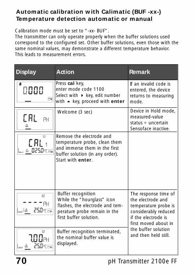
Buffer recognitionWhile the “hourglass” iconflashes, the electrode and tem-perature probe remain in thefirst buffer solution.
Automatic calibration with Calimatic (BUF -xx-)Temperature detection automatic or manual
Press cal key, enter mode code 1100Select with 4 key, edit numberwith 5 key, proceed with enter
Remove the electrode and temperature probe, clean themand immerse them in the firstbuffer solution (in any order). Start with enter.
If an invalid code isentered, the devicereturns to measuringmode.
Buffer recognition terminated,the nominal buffer value isdisplayed.
Device in Hold mode,measured-valuestatus = uncertainSensoface inactive.
Calibration mode must be set to “-xx- BUF”.The transmitter can only operate properly when the buffer solutions usedcorrespond to the configured set. Other buffer solutions, even those with thesame nominal values, may demonstrate a different temperature behavior.This leads to measurement errors.
Welcome (3 sec)
The response time ofthe electrode andtemperature probe isconsiderably reducedif the electrode isfirst moved about inthe buffer solutionand then held still.

71
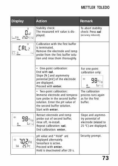
Display Action Remark
Stability check:The measured mV value isdisplayed.
To abort stabilitycheck: Press cal.(accuracy reduced)
Calibration with the first bufferis terminated. Remove the electrode and tempprobe from the first buffer solu-tion and rinse them thoroughly.
• One-point calibration:End with cal.Slope [%] and asymmetrypotential [mV] of the electrodeare displayed. Proceed withenter.
For one-point calibration only:
• Two-point calibration:Immerse electrode and temperature probe in thesecond buffer solution.Start with enter.
The calibrationprocess runs againas for the firstbuffer.
Retract electrode and tempprobe out of second buffer,rinse off, re-install.Repeat calibration: cal,End calibration: enter.
Slope and asymme-try potential ofelectrode (related to25 °C) are displayed.
pH value and Hold are dis-played alternately. Sensoface is active.Proceed with enter.Hold is deactivated after 20 s.
Security prompt.

72 pH Transmitter 2100e FF
Display Action Remark
Enter the pH value of yourbuffer solution for the propertemperature. While the “hour-glass” icon flashes, the elec-trode and temperature proberemain in the first buffer solu-tion.
Manual calibrationTemperature detection automatic or manual
Press cal key,enter mode code 1100Select with 4key, edit numberwith 5key, proceed with enter.
Remove the electrode and temperature probe, clean themand immerse them in the firstbuffer solution (in any order).
Start with enter.
If an invalid code isentered, the devicereturns to measuringmode.
The response timeof the electrodeand temperatureprobe is consider-ably reduced if theelectrode is firstmoved about in thebuffer solution andthen held still.
(Display approx. 3 sec)Device in Hold mode,measured-value status= uncertainSensoface inactive.
For calibration with manual buffer specification, you must enter the pH valueof the buffer solution used in the device for the proper temperature. Thispresetting enables calibration with any desired buffer solution. The MANcalibration mode and the type of temperature detection are selected in theconfiguration mode.
Welcome
73
Display Action Remark
Stability check:The measured mV value is dis-played.
To abort stabilitycheck: Press cal(accuracy reduced).
Calibration with the first bufferis terminated. Remove the electrode and tempprobe from the first buffer solu-tion and rinse them thoroughly.
• One-point calibration:End with cal.Slope [%] and asymmetrypotential [mV] of the electrodeare displayed. Proceed with enter.
For one-point calibration only:
• Two-point calibration:Immerse electrode and tempera-ture probe in the second buffersolution. Enter the pH value ofthe second buffer solution.Start with enter.
The calibrationprocess runs againas for the firstbuffer.
Retract electrode and tempprobe out of second buffer,rinse off, re-install.Repeat calibration: cal,End calibration: enter.
Slope and asymme-try potential ofelectrode (related to25 °C) are displayed.
Security prompt.pH value and “Hold” aredisplayed alternately.Sensoface is active.Proceed with enter.Hold is deactivated after 20 s.

74 pH Transmitter 2100e FF
Display Action Remark
Enter asymmetry potential[mV]. Select with 4 key, edit number with 5 key,proceed with enter.
Data entry of premeasured electrodes
Ready for calibration
If an invalid code isentered, the devicereturns to measuringmode.
(Display approx. 3 sec)Device in Hold mode,measured-value status= uncertainSensoface inactive.
You can directly enter the values for slope and asymmetry potential of anelectrode. The values must be known, e.g. determined beforehand in thelaboratory.The DAT calibration mode must be preset in the configuration mode.
Enter slope [%]. Select with 4key, edit number with 5 key,proceed with enter.
The device displays the newslope and asymmetry potential(at 25 °C).Proceed with enter.
pH value and “Hold” aredisplayed alternately.Sensoface active.Proceed with enter.Hold is deactivated after 20 sec.
Security prompt.
Press cal key, enter mode code 1100Select with 4 key,edit number with 5 key, proceed with enter.

75
Convert slope [%] to slope [mV/pH] at 25 °C:
% mV/pH78 46.280 47.482 48.584 49.786 50.988 52.190 53.392 54.594 55.696 56.898 58.0100 59.2102 60.4
Convertingasymmetry potential in electrode zero point:
ZERO = 7 –VAS[mV]
S [mV / pH]
ZEROVASS
Electrode zero pointAsymmetry potentialSlope

76 pH Transmitter 2100e FF
Product calibration (calibration with sampling)
1. Depending on the display configuration, a pH or an ORP product calibration is performed.
2. For product calibration via Foundation Fieldbus, see Pg 90.During product calibration the electrode remains in the process.The measurement process is only interrupted briefly.
Procedure: During sampling the currently measured value isstored in the transmitter. The device immediately returns tomeasuring mode. The calibration mode indicator flashes and reminds you thatcalibration has not been terminated. The sample is measured in the lab or directly on the site usinga portable meter. To ensure an exact calibration, the sampletemperature should correspond to the measured process tem-perature. The measured sample value is then entered in thetransmitter. From the difference between the stored measuredvalue and entered sample value, the transmitter calculates thenew asymmetry potential (one-point calibration). If the sample is invalid, you can take over the value stored dur-ing sampling. In that case the old calibration values are stored.Afterwards, you can start a new product calibration.
Display Action Remark
Press cal,Enter mode code 1105(Press 4 key to select position,enter number using 5 key,confirm with enter)
If an invalid code isentered, the devicereturns to measuringmode.
Product calibration step 1: (Display approx. 3 sec)

77
Display Action Remark
Measuring mode:
From the flashing CAL modeindicator you see that productcalibration has not been termi-nated.
Product calibration step 2:When the sample value hasbeen determined, call up theproduct calibration once more(cal, mode code 1105).
Display (approx. 3 sec)Device in Hold mode,measured-value status= uncertain,Sensoface inactive.
Enter lab value. The new asym-metry potential is calculated.
Until the samplevalue is determinedand can be entered,the device is inmeasuring mode.
Display of slope and newasymmetry potential (related to 25°C).End calibration with enter.
The measured value is shown inthe main display alternatelywith “Hold”; “enter” flashes.End with enter.
After end of calibra-tion, the outputsremain in Holdmode for approx.20 sec.
New calibration:Press cal.
Take sample and store value.Proceed with enter
Now the sample canbe measured in thelab.

78 pH Transmitter 2100e FF
ORP calibration
The potential of a redox electrode is calibrated using a redox (ORP) buffersolution. In the course of that, the difference between the measured poten-tial and the potential of the calibration solution is determined according tothe following equation. During measurement the transmitter adds thisdifference to the measured potential.
0102025304050607080
Temperature[°C]
Ag/AgCl/KCl1 mol/l[∆mV]
Ag/AgCl/KCl3 mol/l[∆mV]
Thalamid[∆mV]
Mercurysulfate[∆mV]
249244240236233227221214207200
224217211207203196188180172163
-559-564-569-571-574-580-585-592-598-605
672664655651647639631623613603
Temperature dependence of commonly usedreference systems
The electrode potential can also be related to another reference system –e.g. the standard hydrogen electrode. In that case the temperature-corrected potential (see table) of the reference electrode used must beentered during calibration. During measurement, this value is then addedto the ORP measured.Please make sure that measurement and calibration temperature are thesame since the temperature behavior of the reference electrode is notautomatically taken into account.
mVORP = mVmeas + ∆mVmVORP =mVmeas =∆mV =
displayed ORPdirect electrode potentialdelta value, determined during calibration

79
Display Action Remark
Activate calibration(Press cal).Enter mode code 1109Select with 4 key, edit numberwith 5 key, proceed with enter.
Remove the electrode and tem-perature probe, clean them andimmerse them in the redoxbuffer.
If an invalid code isentered, the devicereturns to measuringmode.
Display (approx.3 sec)Device is in Holdmode.
Enter desired value for redoxbuffer (Secondary display:Electrode potential displayed forapprox. 6 sec) Select with 4 key,edit number with 5 key,proceed with enter.
After approx. 6 secthe secondarydisplay shows themeasured tempera-ture.
Display of electrode data(delta value)Proceed with enter.Rinse electrode and temperatureprobe and reinstall them.
“Zero” and “enter”icons are flashing,Sensoface is active.
The measured ORP value [mV] isshown in the main display alter-nately with “Hold”, Sensoface isactive, “enter” flashes.End with enter.
Safety promptAfter end of calibra-tion, the outputsremain in Holdmode for approx.20 sec.
80 pH Transmitter 2100e FF
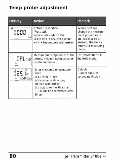
Display Action Remark
Enter measured temperaturevalue.Select with 4 key, edit number with 5 key,proceed with enter.End adjustment with enter.HOLD will be deactivated after20 sec.
Temp probe adjustment
Activate calibration(Press cal,enter mode code 1015)Select with 4key, edit numberwith 5key, proceed with enter.
Measure the temperature of theprocess medium using an exter-nal thermometer
Wrong settingschange the measure-ment properties! Ifan invalid code isentered, the devicereturns to measuringmode.
Default:Current value ofsecondary display.
The transmitter is inthe Hold mode.

81
Calibration error messages
Asymmetry potential out of range (±60 mV)• Electrode worn out• Buffer solution contaminated• Buffer does not belong to configured buffer set• Temperature probe not immersed in buffer
solution (for automatic temperature compensation)
• Wrong buffer temperature selected (for manual temperature specification)
• Nominal electrode zero point ≠ pH 7
Symbol flashes:ProblemPossible causes
Problems during recognition of the buffer solution• Same or similar buffer solution was used for
both calibration steps• Buffer solution used does not belong to
buffer set currently configured in the device
Electrode slope out of range (80-103 %)• Electrode worn out• Buffer solution contaminated• Buffer does not belong to configured buffer set• Temperature probe not immersed in buffer
solution (for automatic temperature compensation)
• Wrong buffer temperature set (for manual temperature specification)
• Electrode used has different nominal slope
82 pH Transmitter 2100e FF
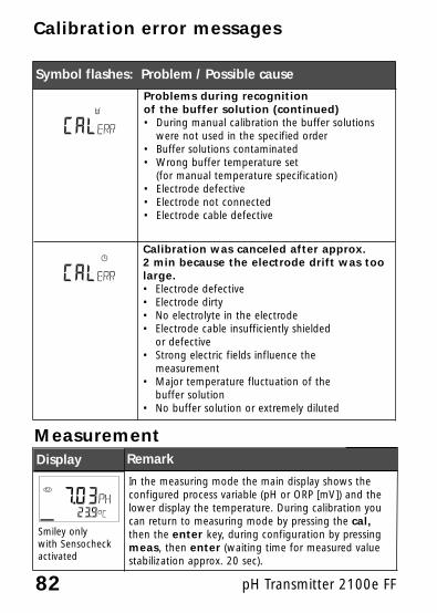
Problems during recognition of the buffer solution (continued)• During manual calibration the buffer solutions
were not used in the specified order• Buffer solutions contaminated• Wrong buffer temperature set
(for manual temperature specification)• Electrode defective• Electrode not connected• Electrode cable defective
Symbol flashes: Problem / Possible cause
Calibration was canceled after approx.2 min because the electrode drift was toolarge.• Electrode defective• Electrode dirty• No electrolyte in the electrode• Electrode cable insufficiently shielded
or defective• Strong electric fields influence the
measurement• Major temperature fluctuation of the
buffer solution• No buffer solution or extremely diluted
Calibration error messages
Display Remark
Measurement
In the measuring mode the main display shows theconfigured process variable (pH or ORP [mV]) and thelower display the temperature. During calibration youcan return to measuring mode by pressing the cal,then the enter key, during configuration by pressingmeas, then enter (waiting time for measured valuestabilization approx. 20 sec).
Smiley onlywith Sensocheckactivated

83
Diagnostics functions
Display Remark
Cal info: Display of calibration dataPress cal while in measuring mode and enter modecode “0000”. The slope is shown in the main display,the asymmetry potential in the secondary display.After 20 sec the device returns to measuring mode(immediate return at pressing enter).
Sensor monitor: Display of uncorrectedelectrode potentialPress meas + cal while in measuring mode and entermode code “2222”. The (uncompensated) electrodepotential is shown in the main display, the measuringtemperature in the secondary display. At pressingenter or 5 the display switches to ORP indication.Press meas to end sensor monitor and return tomeasuring mode.
Error info: Display of last error messagePress meas + cal while in measuring mode and entermode code “0000”. The last error message is displayedfor approx. 20 sec. After that the message will be deleted.(immediate return to measurement at pressing enter).
Smiley onlywith Sensocheckactivated

84 pH Transmitter 2100e FF
SensocheckContinuously monitors the electrodes and wires for short cir-cuits or open circuits. Critical values make the Sensoface “sad”and the corresponding icon flashes:
Sensocheck messages are also output as error messages Err 33and Err 34. The red LED lights. Sensocheck can be switched off during configuration (thenSensoface is also disabled). Exception: After a calibration asmiley is always displayed for confirmation.
Sensoface(Sensocheck must have been activated during configuration.)
The smiley in the display (Sensoface) alerts to electrode prob-lems (defective sensor, defective cable, maintenance required).The permitted calibration ranges and the conditions for afriendly, neutral, or sad Sensoface are summarized in the fol-lowing chart. Additional icons refer to the error cause.
NoteThe worsening of a Sensoface criterion leads to the devaluationof the Sensoface indicator (Smiley becomes “sad”). Animprovement of the Sensoface indicator can only take placeafter calibration or removal of an electrode defect.

85
StatusDisplay Problem
Asymmetrypotential andslope
Asymmetry potential (zero) and slopeof the electrode are still okay,However, the electrode should bereplaced soon.
Asymmetry potential (zero point)and/or slope of the electrode havereached values which no longerensure proper calibration. Replace the electrode.
Cal timer Over 80 % of the calibration intervalhas already past.
The calibration interval has beenexceeded.
Electrodedefective
Check the electrode and itsconnections(also see error messagesErr 33 and Err 34, see Pg 116).
To remove dust, dirt and spots, the external surfaces of thedevice may be wiped with a damp, lint-free cloth. A mildhousehold cleaner may also be used if necessary.
Cleaning
Sensoface evaluation limits

86 pH Transmitter 2100e FF
Resource block (RB)
Block status:The RS_STATE parameter indicates the operating status of theresource block:
• Standby The resource block is in OOS mode. The other blocks cannot be executed.
• Online The resource block is in Auto mode, that is normal state.
Write protection:With the WRITE_LOCK parameter, you can set a write protec-tion for the device.• UNLOCKED Device can be written to (default)• LOCKED Device is locked.
Key lock:With the DEVICE_LOCK parameter, you can set a key lock.• UNLOCKED Device can be operated via keypad.• LOCKED Key lock is active.
Communication Fieldbus / Device

87
AlarmThe BLOCK_ALM parameter sends the status of the process alarmsto the control system. This parameter specifies whether an alarmmust be acknowledged via the control system.
For bus parameters of resource block, see Pg 88.

88 pH Transmitter 2100e FF
Communication Fieldbus / DeviceBus Parameters Resource Block (RB)
12345
6789
10
11121314
151617
18
19
20
21
2223
Static revisionTAG descriptionStrategyAlert keyTargetActualPermittedNormalBlock errorResource stateTestDD resourceManufacturer ID
Device typeDevice revisionDD revisionGrantDenyHardware typeRestartFeature supported
Feature selected
Cycle type
Cycle selected
Min cycle time
Memory sizeNon-volatile cycle time
0
00OOS-OOS, AutoAuto
1
0x465255 forMettler-Toledo 210011001
Reports/ Soft W LockReports/ Soft W LockScheduled/Block executionScheduled/Block execution1600 1/32 msec(50ms)
RR/WR/WR/WR/W
RRR/WRR
RRRR/WR/WRR/WR
R/W
R
R/W
R
RR
Index
ST_REVTAG_DESCSTRATEGYALERT_KEYMODE_BLK
BLOCK_ERRRS_STATETEST_RWDD_RESOURCEMANUFAC_ID
DEV_TYPEDEV_REVDD_REVGRANT_DENY
HARD_TYPESRESTARTFEATURES
FEATURES
CYCLE_TYPE
CYCLES_SEL
MIN_CYCLE_T
MEMORY_SIZENV_CYCLE_T
Description Default R/WParameter
42 DEVICE_LOCK Locks the device for local access.
Ind
ex
Mettler-Specific Parameter Description
89
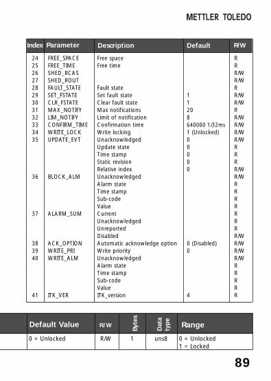
242526272829303132333435
36
37
383940
41
Free spaceFree time
Fault stateSet fault stateClear fault stateMax notificationsLimit of notificationConfirmation timeWrite lockingUnacknowledgedUpdate stateTime stampStatic revisionRelative indexUnacknowledgedAlarm stateTime stampSub-codeValueCurrentUnacknowledgedUnreportedDisabledAutomatic acknowledge optionWrite priorityUnacknowledgedAlarm stateTime stampSub-codeValueITK_version
11208640000 1/32ms1 (Unlocked)00000
0 (Disabled)0
4
RRR/WR/WRR/WR/WRR/WR/WR/WR/WRRRR/WR/WRRRRRRRR/WR/WR/WR/WRRRRR
FREE_SPACEFREE_TIMESHED_RCASSHED_ROUTFAULT_STATESET_FSTATECLR_FSTATEMAX_NOTIFYLIM_NOTIFYCONFIRM_TIMEWRITE_LOCKUPDATE_EVT
BLOCK_ALM
ALARM_SUM
ACK_OPTIONWRITE_PRIWRITE_ALM
ITK_VER
Index Description Default R/WParameter
0 = Unlocked R/W 1 uns8 0 = Unlocked1 = Locked
Default Value R/W
Byt
es
Dat
aty
pe
Range

90 pH Transmitter 2100e FF
Communication Fieldbus / DeviceTransducer Block (TB)
ConfigurationIn the Transducer Block you can configure the device viaFieldbus. The required parameters are listed in the table onPg 92.
CalibrationWith 3 parameters, product calibration for pH and ORP can beperformed via Fieldbus.
pH product calibration via Fieldbus.1.Set CAL_SAMPLE_PRD_PH parameter to sample.
The device stores the pH value of the sample.After the writing, the parameter is automatically reset to NOP (no operation).
2.Read out CAL_SAMPLE_PRD_PH_STORED_VAL parameter. It contains the stored value.
3.Write lab value of the sample in the CAL_PRODUCT_PH parameter.The CAL_SAMPLE_PRD_PH_STORED_VAL parameter is resetto zero. Now the device is calibrated.
Note:When step 1 has been performed directly on the site on thedevice, the operation on the Fieldbus as described in point 1 isomitted.

91
ORP product calibration via FieldbusSame as for pH – only that ORP parameters must be used.
The calibration values can also be entered directly in theCAL_SLOPE_PH, CAL_ZERO_PH, and CAL_ZERO_ORPparameters.
Error messagesThe LAST_ERROR parameter always indicates the last error:
01 pH electrode02 Redox electrode03 Temperature probe33 Glass electrode34 Reference electrode98 System error99 Factory settings
If now a “BAD” status occurs for the OUT_Value in the AnalogInput, the user can take this parameter to draw conclusionsabout the problem.
For bus parameters of transducer block, see Pg 92.
92 pH Transmitter 2100e FF
Communication Fieldbus / DeviceBus Parameters of Standard Transducer Block (TB)
Ind
ex Parameter Description
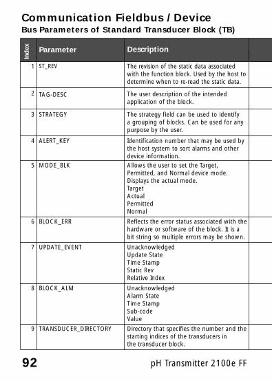
1 ST_REV The revision of the static data associatedwith the function block. Used by the host todetermine when to re-read the static data.
2 TAG-DESC The user description of the intended application of the block.
3 STRATEGY The strategy field can be used to identify a grouping of blocks. Can be used for any purpose by the user.
4 ALERT_KEY Identification number that may be used bythe host system to sort alarms and other device information.
5 MODE_BLK Allows the user to set the Target,Permitted, and Normal device mode.Displays the actual mode.TargetActualPermittedNormal
6 BLOCK_ERR Reflects the error status associated with thehardware or software of the block. It is abit string so multiple errors may be shown.
7 UPDATE_EVENT UnacknowledgedUpdate StateTime StampStatic RevRelative Index
8 BLOCK_ALM UnacknowledgedAlarm StateTime StampSub-codeValue
9 TRANSDUCER_DIRECTORY Directory that specifies the number and thestarting indices of the transducers in the transducer block.

93
Default Value R/W
Byt
es
Dat
aty
pe
Range
The revision value is incrementedevery time a static parameter in theblock is changed.
R 2
Text R/W 32
Default=0 R/W 2
Default=0 R/W 1
Available Modes:Automatic, Out Of Service(OOS), Manual
R/WRR/WR/W
1111
R 2
00000
R 11822
00000
R 11821
R 4

94 pH Transmitter 2100e FF
Communication Fieldbus / DeviceBus Parameters of Standard Transducer Block (TB)
Ind
ex Parameter Description
10 TRANSDUCER_TYPE Identifies the transducer type.
11 XD_ERROR A transducer block sub-code. XD_ERRORcontains the highest priority alarm thathas been activated in the TB_DETAILED_STATUS parameter.
12 COLLECTION_DIRECTORY A directory that specifies the number,starting indices, and DD item of ID's ofthe data collection in each transducerwithin a transducer block. Used by thehost for efficient transfer of information.
Mettler-Specific Parameters – Output
13 PRIMARY_VALUE_TYPE pH/ORP
14 PRIMARY_VALUE The pH value and status: ValueStatus
15 PRIMARY_VALUE_RANGE Shows the range of the pvHigh RangeLow RangeUnit IndexDecimal Point
16 SENSOR_TYPE_PH e.g. Glass, ISFET
17 SENSOR_MV Sensor output in mV
18 SECONDARY_VALUE_1 Process ORP value and statusValueStatus
19 SECONDARY_VALUE_UNIT_1
20 ISO_POTENTIAL Isopotential pH value
21 SECONDARY_VALUE_2 Process temperature value and statusValueStatus

95
Default Value R/W
Byt
es
Dat
aty
pe
Range
65535 = other R 2
0 R 1
R 36
0 = pH R/W 2 uns 16 0 = pH1 = ORP
R 41
DS-65
16pH-2pH1422 (pH)2
RRRR
4421
DS-68 -2 ... +16
0 = Glass R/W 2 uns 16 0 = Glass1 = ISFET
R 2 float
RR
41
DS-68 -1500...1000mV
1243 = mV R 2 uns 16
7.00 pH R 4 float
RR
41
DS-65 -20 ... +200 °C
96 pH Transmitter 2100e FF
Communication Fieldbus / DeviceBus Parameters of Standard Transducer Block (TB)
Ind
ex
Parameter Description
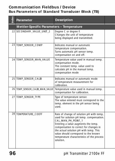
22 SECONDARY_VALUE_UNIT_2 Degree C or degree F.Changes the unit of temperaturebeing displayed and transmitted.
23 TEMP_SENSOR_COMP Indicates manual or automatic temperature compensation.Turns automatic pH sensor temp.compensation on and off.
24 TEMP_SENSOR_MAN_VALUE Temperature value used in manual temp.compensation mode.The constant temp. value used to calculate pH in the manual temp.compensation mode
25 TEMP_SENSOR_CALIB Indicates manual or automatic mode of temperature measurement forcalibration.
26 TEMP_SENSOR_CALIB_MAN_VALUE Temperature value used in manual temp.compensation for calibration.
27 TEMP_SENSOR_TYPE Type of temperature sensor.The value entered must correspond to thetemp. element in the pH sensor beingused.
28 TEMPERATURE_COEFF Rate of change of solution pH with temp,used for solution pH temp. compensation.CAL_MAN_PH_POINT_1Entering a value augments the temp.compensation to correct for changes inthe actual solution pH with temp. This value should correspond to the knowntemperature characteristics of the processsolution.
Mettler-Specific Parameters – Temperature

97
Default Value R/W
Byt
es
Dat
aty
pe
Range
1001 = °C R/W 2 uns16 1001 = °C1002 = °F
0 = Automatic R/W 1 uns8 0 = Automatic1 = Manual
R/W 4 float -20 ... +200 °C
0 = Automatic R/W 1 uns8 0 = Automatic1 = Manual
R/W 4 float -20 ... +200 °C
128 = Pt100 R/W 2 uns16 128 = Pt100200 = Pt10001000 = NTC301001 = NTC8.55
Typically 0.00, unless solution pH temperature compensation isbeing used.
R/W 4 float -19.99...+19.99

98 pH Transmitter 2100e FF
Communication Fieldbus / DeviceBus Parameters of Standard Transducer Block (TB)
29 TEMP_WIRE_IMPEDANCE Sets the wire impedance of the temp. sensor. Typically 0 unless the wire of thesensor gets too long.
30 TEMP_SENSOR_CAL Desired temperature reading, used fortemperature measurement calibration.The temp. value entered for a single pointtemp. standardization.
31 GLASS_IMPEDANCE Sensor glass electrode impedanceValueStatus
32 REFERENCE_IMPEDANCE Sensor reference electrode impedanceValueStatus
33 CAL_MAN_PH_POINT_1 pH of buffer solution used in a manualbuffer calibration.
34 CAL_MAN_PH_POINT_2 pH of buffer solution used in a manualbuffer calibration.
35 CAL_SLOPE_PH The slope of the pH electrode in %
36 CAL_ZERO_PH The zero offset resulting from a buffer calibration or a standardization
Index Parameter Description
Mettler-Specific Parameters – Calibration
Mettler-Specific Parameters – Temperature
Mettler-Specific Parameters – Impedance

99
0 Ohm R/W 4 float 0...1000Ohm
R/W 4 float -10...+10K
RR
41
DS-65 0...2000MOhm
RR
41
DS-65 0...200kOhm
R/W 4 float -2 ... +16pH
R/W 4 float -2 ... +16pH
Theoretical value is 100% = 59.16mV/pH,but the actual value is determinedby a 2 point buffer calibration.
R/W 4 float 80 ... 103%
Theoretical value is 0.00 mV, butactual value will depend upon thecharacteristics of the pH sensorfield -60mV ... +60mV.
R/W 4 float -60...+60mV
Default Value R/W
Byt
es
Dat
aty
pe
Range

100 pH Transmitter 2100e FF
Communication Fieldbus / Device
Bus Parameters of Standard Transducer Block
37 CAL_OFFSET_ISFET Sets the offset of the ISFET.
38 CAL_ZERO_ORP The zero offset resulting from a buffer cal-ibration.
39 CALIBRATION_TIMER Sets the calibration timer(time in which the device should becalibrated).
40 CALIBRATION_MODE Sets the calibration mode.
41 CALIBRATION_MODE_BUFFER Sets the buffer set forCALIBRATION_MODE.= BUF
42 CAL_SAMPLE_PRD_PH Starts the 1st part of pH-product calibra-tion.
43 CAL_SAMPLE_PRD_PH_STORED_VAL
Shows the stored value of the first step of pH-product calibration
44 CAL_PRODUCT_PH Sets the value for the 2nd part of pH-product calibration.
45 CAL_SAMPLE_PRD_ORP Starts the 1st part of ORP-product calibration.
46 CAL_SAMPLE_PRD_ORP_STORED_VAL
Shows the stored value of the first step of ORP-product calibration
47 CAL_PRODUCT_ORP Sets the value for the 2nd part of ORP-product calibration.
Ind
ex
Parameter Description
Mettler-Specific Parameters – Calibration
101
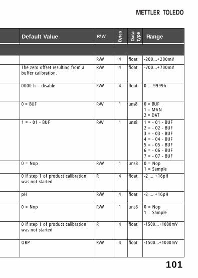
R/W 4 float -200...+200mV
The zero offset resulting from abuffer calibration.
R/W 4 float -700...+700mV
0000 h = disable R/W 4 float 0 ... 9999h
0 = BUF R/W 1 uns8 0 = BUF1 = MAN 2 = DAT
1 = - 01 - BUF R/W 1 uns8 1 = - 01 - BUF2 = - 02 - BUF3 = - 03 - BUF4 = - 04 - BUF5 = - 05 - BUF6 = - 06 - BUF7 = - 07 - BUF
0 = Nop R/W 1 uns8 0 = Nop1 = Sample
0 if step 1 of product calibrationwas not started
R 4 float -2 ... +16pH
pH R/W 4 float -2 ... +16pH
0 = Nop R/W 1 uns8 0 = Nop1 = Sample
0 if step 1 of product calibrationwas not started
R 4 float -1500...+1000mV
ORP R/W 4 float -1500...+1000mV
Default Value R/W
Byt
es
Dat
aty
pe
Range
102 pH Transmitter 2100e FF
Communication Fieldbus / Device
Bus Parameters of Standard Transducer Block (TB)
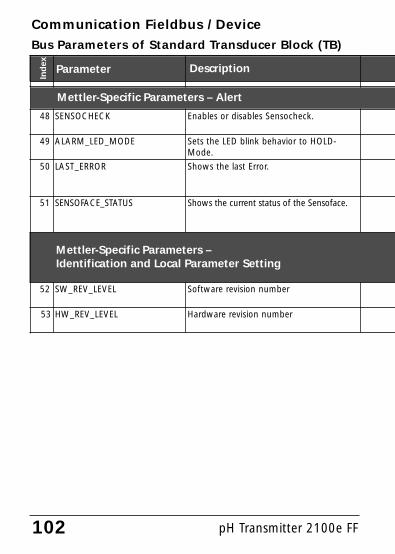
48 SENSOCHECK Enables or disables Sensocheck.
49 ALARM_LED_MODE Sets the LED blink behavior to HOLD-Mode.
50 LAST_ERROR Shows the last Error.
51 SENSOFACE_STATUS Shows the current status of the Sensoface.
52 SW_REV_LEVEL Software revision number
53 HW_REV_LEVEL Hardware revision number
Index Parameter Description
Mettler-Specific Parameters – Alert
Mettler-Specific Parameters – Identification and Local Parameter Setting

103
0 = Off R/W 1 uns8 0 = Off1 = On
0 = Off R/W 1 uns8 0 = Off1 = On
0 = None R 2 uns8 0...100
0 = Good R 1 uns8 0 = Good1 = Neutral2 = Bad
R 2 uns8
R 1 uns8
Default Value R/W
Byt
es
Dat
aty
pe Range

104 pH Transmitter 2100e FF
Setting the operating modeThe following operating modes can be set in the MODE_BLKparameter: • OOS • MAN • AutoWhen there is no write protection, the OOS mode allowsunlimited access to all parameters.
Selecting the process variables and unitsThe pH Transmitter 2100e FF provides 3 Analog Input blocks.The respective process variable can be selected in theCHANNEL parameter.The corresponding measurement unit is selected in the UNITSsubparameter of the XD_SCALE parameter.The following variables are available:
Communication Fieldbus / DeviceAnalog Input Blocks (AI) of pH Transmitter 2100e FF
CHANNEL 1 pH pHCHANNEL 2 ORP mVCHANNEL 3 Temperature °C / °FCHANNEL 4 Glass impedance MOhmCHANNEL 5 Ref. impedance kOhmCHANNEL 6 Slope %CHANNEL 7 Asymmetry potential mV
Linearization typesThe input value can be linearized in the AI with the LIN_TYPEparameter:
• DirectThe measured value is directly led from the Transducer block tothe Analog Input block, avoiding the linearization function.Here, you must make sure that the units in the XD_SCALE andOUT_SCALE parameters are identical.

105
• IndirectHere, the measured value of the TB is linearly scaled over theinput scale (XD_SCALE) to the output scale (OUT_SCALE).
• Indirect Square RootThe input value is rescaled over the XD_SCALE parameter andrecalculated using a root function. Then the value is furtherscaled to OUT_SCALE.
DiagnosticsThe BLOCK_ERR parameter indicates the current block status.
Alarm handlingThe process control system receives the alarm status via theBLOCK_ALM parameter. In the ACK_OPTION parameter youspecify whether an alarm must be acknowledged via the controlsystem.
Block alarmsAn AI can generate the following block alarms via theBLOCK_ERR parameter:
• Simulate Active • Input Failure• Block Configuration Error • Out Of Service
Limit alarmsIf a measured value falls below or exceeds the defined limit inthe AI block OUT parameter, the control system is alerted.The following limit parameters are defined:• HI_HI_LIM • HI_LIM• LO_LIM • LO_LO_LIM
The behavior is defined by the respective priorities.
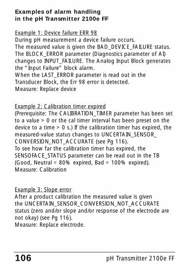
Examples of alarm handling in the pH Transmitter 2100e FF
Example 1: Device failure ERR 98During pH measurement a device failure occurs. The measured value is given the BAD_DEVICE_FAILURE status. The BLOCK_ERROR parameter (Diagnostics parameter of AI)changes to INPUT_FAILURE. The Analog Input Block generatesthe “Input Failure” block alarm.When the LAST_ERROR parameter is read out in theTransducer Block, the Err 98 error is detected.Measure: Replace device
106 pH Transmitter 2100e FF
Example 2: Calibration timer expired(Prerequisite: The CALIBRATION_TIMER parameter has been setto a value > 0 or the cal timer interval has been preset on thedevice to a time > 0 s.) If the calibration timer has expired, themeasured-value status changes to UNCERTAIN_SENSOR_CONVERSION_NOT_ACCURATE (see Pg 116). To see how far the calibration timer has expired, the SENSOFACE_STATUS parameter can be read out in the TB(Good, Neutral = 80% expired, Bad = 100% expired).Measure: Calibration
Example 3: Slope errorAfter a product calibration the measured value is given the UNCERTAIN_SENSOR_CONVERSION_NOT_ACCURATEstatus (zero and/or slope and/or response of the electrode arenot okay) (see Pg 116).Measure: Replace electrode.

107
Alarm diagnostics / Bus parametersIn the case of an alarm the following bus parameters must beevaluated:
• AI block OUT parameter (currently measured value)• TB LAST_ERROR parameter (error indication 1 ... 100)• TB SENSOFACE_STATUS parameter
(0 = Good, 1 = Neutral, 2 = Bad)

108 pH Transmitter 2100e FF
Communication Fieldbus / DeviceBus Parameters / Analog Input Blocks
12345
67
8
9
10
11
12
13141516171819
20
Static RevisionTAG DescriptionStrategyAlert KeyTargetActualPermittedNormalBlock ErrorProcess ValueStatusMeasured ValueStatusSimulate StatusSimulate ValueTransducer StatusTransducer ValueSimulate Enable/ DisableHigh RangeLow RangeUnits IndexDecimal PointHigh RangeLow RangeUnits IndexDecimal PointGrantDenyIO Block OptionsStatus OptionsChannelLinearization typeLow Cut OffFilter TimePercent ValueStatusUnacknowledgedUpdate StateTime StampStatic RevisionRelative Index
0
00OOS-OOS, AutoAuto
100000100000000
1000
00000
RR/WR/WR/WR/W
RRRRRR/WR/WRRR/WR/WR/WR/WR/WR/WR/WR/WR/WR/WR/WR/W
R/WR/WR/WR/WRRR/WRRRR
ST_REVTAG_DESCSTRATEGYALERT_KEYMODE_BLK
BLOCK_ERRPV
OUT
SIMULATE
XD_SCALE
OUT_SCALE
GRANT_DENY
IO_OPTSSTATUS_OPTSCHANNELL_TYPELOW_CUTPV_TIMEFIELD_VAL
UPDATE_EVT
Index Description Default R/WParameter

109
21
22
2324252627282930313233
34
35
36
UnacknowledgedAlarm StateTime StampSubcodeCurrentUnacknowledgedUnreportedDisabledAutomatic Acknowledge OptionAlarm HysteresisHigh High PriorityHigh High LimitHigh PriorityHigh LimitLow PriorityLow LimitLow Low PriorityLow Low LimitUnacknowledgedAlarm StateTime StampSubcodeValueUnacknowledgedAlarm StateTime StampSubcodeValueUnacknowledgedAlarm StateTime StampSubcodeValueUnacknowledgedAlarm StateTime StampSubcodeValue
0000000000.50%0INF0INF0- INF0- INF00000000000000000000
R/WRRRRRRR/WR/WR/WR/WR/WR/WR/WR/WR/WR/WR/WR/WRRRRR/WRRRRR/WRRRRR/WRRRR
BLOCK_ALM
ALARM_SUM
ACK_OPTIONALARM_HYSHI_HI_PRIHI_HI_LIMHI_PRIHI_LIMLO_PRILO_LIMLO_LO_PRILO_LO_LIMHI_HI_ALM
HI_ALM
LO_ALM
LO_LO_ALM
Index Description Default R/WParameter

110 pH Transmitter 2100e FF
Cyclic measured value statusPr
iori
ty
Qu
alit
y
Sub-status
Bin
cod
ing
wit
ho
ut
limit
bit
s
Hex
cod
ing
Low
High
Good Good non-specific 10 00 00 00 0 x 80
Good active advisory alarm 10 00 10 xx 0 x 88
Good active critical alarm 10 00 11 xx 0 x 8C
Uncer-tain
Uncertain non-specific 01 00 00 xx 0 x 40
Last Usable Value (LUV) 01 00 01 xx 0 x 44
Substitute set 01 00 10 xx 0 x 48
Initial value 01 00 11 xx 0 x 4C
Sensor conversion notaccurate
01 01 00 xx 0 x 50
Engineering unit violation 01 01 01 xx 0 x 54
Sub-normal 01 01 10 xx 0 x 58
Bad Non-specific 00 00 00 xx 0 x 00
Sensor failure 00 01 00 xx 0 x 10
Device value 00 00 11 xx 0 x 0C
Out of service 00 01 11 xx 0 x 1C
Communication Fieldbus / Device

111
Bin coding of limit bits Meaning of limit bits
00 ok
01 Low limited
10 High limited
11 Constant
Limit bits
The respective status bit is set when the condition occurs. It isreset as soon as the condition does not exist any more.
When the measured-value status is “bad”, the AI blockBLOCK_ERR parameter indicates an “Input Failure”.

pH Transmitter 2100e FF112
Operating states / Measured value status
Operating state(Activation)
Red LED Time out
Measuring live - good
Cal Info(cal) 0000
live 20 s good
Error Info(meas + cal) 0000
live 20 s good
Configuration(meas + cal) 1200
Hold1) 20 min uncertain
last usable value
ISFET calibration(cal) 1001
Hold1) - uncertain
last usable value
pH calibration(cal) 1100
Hold1) - uncertain
last usable value
ORP calibration(cal) 1109
Hold1) - uncertain
last usable value
Temp probe adjust-ment (cal) 1015
Hold1) - uncertain
last usable value
Product calibration(pH +ORP)Step 1 (cal) 1105
live- good
Step 2(cal) 1105 Hold
1) - uncertainlast usable value
Sensor monitor(meas + cal) 2222
live 20 min good
StatusAI pH

1131) LED flashes when “HOLD ON” has been set (see Pg 67).
Status AI ORP
StatusAI Temp
StatusglassimpedanceAI Rglass
StatusreferenceimpedanceAI Rref
good good good good
good good good good
good good good good
uncertainlast usable value
uncertainlast usable value
uncertainlast usable value
uncertainlast usable value
uncertain last usable value
uncertainlast usable value
uncertainlast usable value
uncertainlast usable value
uncertainlast usable value
uncertainlast usable value
uncertainlast usable value
uncertainlast usable value
uncertainlast usable value
uncertainlast usable value
uncertainlast usable value
uncertainlast usable value
uncertainlast usable value
uncertainlast usable value
uncertainlast usable value
uncertainlast usable value
good good good good
uncertainlast usable value
uncertainlast usable value
uncertainlast usable value
uncertainlast usable value
good good good good

114 pH Transmitter 2100e FF
Error Display
Sen
sofa
ce
ERR 99 “FAIL”flashes
Factory settingsEEPROM or RAM defectiveThis error message only occurs inthe case of a total defect. Thedevice must be repaired and recali-brated at the factory.
x
ERR 98 “Conf”flashing
System errorConfiguration or calibration datadefective; completely reconfigureand recalibrate the device.Memory error in device program
x
ERR 01 Measuredvalueflashes
pH electrodeElectrode defective• Too little electrolyte (electrode)• Electrode not connected• Break in electrode cable• Incorrect electrode connected• Value measured for:
pH < –2 or > 16
x
ERR 02 Measuredvalueflashes
Redox electrode• Electrode defective• Electrode not connected• Break in electrode cable• Incorrect electrode connected• Electrode potential < –1500 mV
or > 1000 mV
Error messages / Measured value status
Red
LED
ProblemPossible causes

115
baddevice_failure
baddevice_failure
baddevice_failure
baddevice_failure
baddevice_failure
baddevice_failure
baddevice_failure
baddevice_failure
baddevice_failure
baddevice_failure
badsensor_failure
good good good good
StatusAI pH
Status AI ORP
StatusAI Temp
StatusglassimpedanceAI Rglass
StatusreferenceimpedanceAI Rref
good badsensor_failure
good good good
StatusAI pH
Status AI ORP
StatusAI Temp
StatusglassimpedanceAI Rglass
StatusreferenceimpedanceAI Rref

pH Transmitter 2100e FF116
Error Displayflashes
Sen
sofa
ce
ERR 33 Sensocheck glass el.(not for ISFET)
x x
ERR 34 Sensocheck Ref el. x x
Zero point• Zero error
x
Slope• Slope error
x
Response time• Response time exceeded
x
Cal timer• Calibration timer expired
x
Error messages / Measured value status
Red
LED
ProblemPossible causes
Also see Sensocheck / Sensoface, Pg 84
ERR 03
flashes
Temperature probeOpen or short circuitTemperature range exceeded: <-10°C, -20°C / > 130°C, 150°C, 200°C
x

117
bad 1)
sensor_failuregood good bad
sensor_failure
good
bad 1)
sensor_failurebad 1)
sensor_failuregood good bad
sensor_failure
good good good good
uncertain2)
sensor_conversion_
not _accurate
good good good good
uncertain2)
sensor_conversion_
not _accurate
good good good good
uncertain3)
sensor_conversion_
not _accurate
good good good good
StatusAI pH
Status AI ORP
StatusAI Temp
StatusglassimpedanceAI Rglass
StatusreferenceimpedanceAI Rref
bad 1)
sensor_failuregood bad
sensor_failurebad
sensor_failurebad
sensor_failure
1) For pH: when temperature has been set to “Auto”.2) When Sensocheck has been set to “ON”3) With calibration timer off = 0000h
uncertain2)
sensor_
conversion_not _accurate
StatusAI pH
Status AI ORP
StatusAI Temp
StatusglassimpedanceAI Rglass
StatusreferenceimpedanceAI Rref

118 pH Transmitter 2100e FF

119
Appendix
Product line and accessories
Devices Order no.
pH Transmitter 2100e FF 52 121 245
Mounting accessoriesPipe-mount kit 52 120 741Panel-mount kit 52 120 740Protective hood 52 120 739
SensorsMettler-Toledo GmbH, Process Analytics offers a wide range ofpH and ORP electrodes and ISFET sensors for the followingfields of applications:- Chemical process industry- Pharmaceutical industry- Food and beverage industry- Pulp and paper industry- Water/waste-water treatmentFor more information concerning our sensors and housingsprogram, please refer to our website.
The Device Description (DD file) and the Common File Format(CFF file) for network project are included in the shipment. They can also be downloaded at:
http://www.mtpro.com/transmitters

120 pH Transmitter 2100e FF
pH/mV input Input for glass electrode or ISFETInput Reference electrodeInput Redox electrode (ORP) or solution GND for
impedance measurementMeasurement / Display range pH value -2.00 ... 16.00
ORP -1500 ... +1000 mV
Glass electrode input1)
Input resistance > 0.5 x 10¹² Ohms
Input current < 2 x 10-12 A4)
Reference electrode input1)
Input resistance > 1 x 10¹⁰ Ohms
Input current < 1 x 10⁻¹⁰ A4)
Meas. error1,2,3)
pH value < 0.02 TC: 0.002 pH/K mV value < 1 mV TC: 0.1mV/K
Specifications
Sensor standardization pH *) pH calibrationOperating modes: BUF: Calibration with automatic buffer recognition
Calimatic:Buffer sets-01- Mettler-Toledo
2.00/4.01/7.00/9.21-02- Merck/Riedel de Haen
2.00/4.00/7.00/9.00/12.00-03- Ciba (94)
2.06/4.00/7.00/10.00-04- NIST technical
1.68/4.00/7.00/10.01/12.46-05- NIST standard
1.680/4.008/6.865/9.184-06- HACH
4.00/7.00/10.18-07- WTW technical buffers
2.00/4.01/7.00/10.00MAN Calibration with manual entry of individual
buffer valuesDAT Data entry of premeasured electrodesPRD Product calibration

121
Zero adjustment pH: ±200 mV ORP: -700 ... +700 mVMax. calibration range Asymmetry potential: ±60 mV
Slope: 80 ... 103 % (47.5 ... 61 mV/pH)
Sensor standardization ORP *) ORP calibrationMax. calibration range -700 ... +700 ∆mV
Cal timer 0000 to 9999 h
Sensocheck Automatic monitoring of glass andreference electrode (can be disabled)
Delay Approx. 30 sec
Sensoface provides information on the electrode condition.Evaluation of zero/slope, response, calibration interval, Sensocheck
Sensor monitor Direct display of measured values from sensor for validation
Temperature input *) Pt100/Pt1000/NTC 30 kOhms/NTC 8.55 kOhms2-wire connection, adjustable
Ranges Pt 100/Pt 1000: -20.0 ... +200.0 °C(-4 ... +392 °F)
NTC 30 kOhms -20.0 ... +150.0 °C(-4 ... +302 °F)
NTC 8.55 kOhms -10.0 ... +130.0 °C(-4 ... +266 °F)
Adjustment range 10 KResolution 0.1 °C / 1 °FMeas. error1,2,3) <0.5 K (<1 K for Pt100; <1 K for NTC >100°C)
Temp compensation Linear –19.99 ... +19.99 %/Kof process medium (reference temp 25 °C)

122 pH Transmitter 2100e FF
Specifications
FF communication FF_H1 (Foundation Fieldbus)Physical interface To EN 61 158-2 (IEC 1158-2)Address range 017 ... 246, Factory setting: 026Mode of operation Bus-powered device with constant current
consumptionSupply voltage FISCO ≤ 17.5 V (trapezoidal or
rectangular characteristic)≤ 24 V (linear characteristic)
Current consumption < 12.7 mAMax. current in case of fault (FDE)< 21.4 mA
Power output for operating an ISFET adapter+3 V / 0.5 mA–3 V / 0.5 mA
Display LC display, 7-segment with iconsMain display Character height 17 mm, unit symbols 10 mmSecondary display Character height 10 mm, unit symbols 7 mmSensoface 3 status indicators
(friendly, neutral, sad smiley)
Mode indicators 5 mode indicators “meas”, “cal”, “alarm”,“FF communication”, “config”18 further icons for configuration and messages
Alarm indication Red LED in case of alarm or HOLD, user defined
Keypad 5 keys: [cal] [conf] [4] [5] [enter]
FF communication model Certified to ITK 4.51, DD certified to ITK 4.61 resource block1 transducer block3 AI function blocks Selectable: pH, ORP, temperature, Rglass, Rref,
asymmetry potential, slope
Execution time 50 ms

123
Service functionsDevice self-test Automatic memory test (RAM, ROM, EEPROM)Display test Display of all segmentsLast error Display of last error occurredSensor monitor Display of direct, uncorrected sensor signal
(resistance/temperature)
Data retention Parameters and calibration data > 10 years (EEPROM)
EMC EN 61326Emitted interference: Class B (residential area)Immunity to interference: Industry
FCC: FCC rules part 15/B class A
Lightning protection EN 61000-4-5, Installation Class 2
Nominal operating conditionsAmbient temperature –20 ... +55 °CTransport/Storage temp –20 ... +70 °C
Explosion protection ATEX: II 2(1)G EEx ia IIC T4FM: IS, Class I Div1, Group A, B, C, D T4 FISCO
I / 1[0] / AEx ib [ia] / IIC / T4 FISCONI, Class I Div2, Group A, B, C, D T4 NIFW

124 pH Transmitter 2100e FF
Specifications
Enclosure Molded enclosure made of PBT(polybutylene terephtalate)
Color Bluish gray RAL 7031Mounting • Wall mounting
• Pipe mounting: Ø 40 ... 60 mm, 30 to 45 mm
• Panel mounting, cutout to DIN 43 700Sealed against panel
Dimensions H 144 mm, W 144 mm, D 105 mmProtection IP 65/NEMA 4X
(USA, Canada: indoor use only)Cable glands 3 breakthroughs for cable glands
M20x1.5, 2 breakthroughs for NPT 1/2”or Rigid Metallic Conduit
Weight Approx. 1 kg
*) User-defined1) To IEC 746 Part 1, at nominal operating conditions2) ± 1 count3) Plus sensor error4) Doubles every 10 K
The connections to the Transmitter must be installedin accordance with the National Electric Code (ANSI-NFPA 70) Division 2 hazardous (classified) locationnon-incendive wiring techniques.
Division 2 wiring
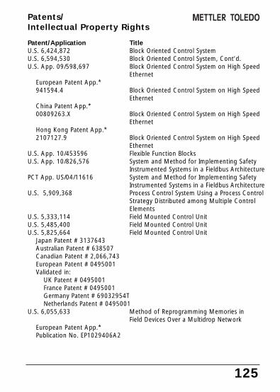
125
Patent/Application TitleU.S. 6,424,872 Block Oriented Control System U.S. 6,594,530 Block Oriented Control System, Cont’d.U.S. App. 09/598,697 Block Oriented Control System on High Speed
Ethernet European Patent App.*941594.4 Block Oriented Control System on High Speed
EthernetChina Patent App.* 00809263.X Block Oriented Control System on High Speed
EthernetHong Kong Patent App.*2107127.9 Block Oriented Control System on High Speed
EthernetU.S. App. 10/453596 Flexible Function BlocksU.S. App. 10/826,576 System and Method for Implementing Safety
Instrumented Systems in a Fieldbus ArchitecturePCT App. US/04/11616 System and Method for Implementing Safety
Instrumented Systems in a Fieldbus ArchitectureU.S. 5,909,368 Process Control System Using a Process Control
Strategy Distributed among Multiple Control Elements
U.S. 5,333,114 Field Mounted Control UnitU.S. 5,485,400 Field Mounted Control UnitU.S. 5,825,664 Field Mounted Control Unit
Japan Patent # 3137643Australian Patent # 638507Canadian Patent # 2,066,743European Patent # 0495001Validated in:
UK Patent # 0495001France Patent # 0495001Germany Patent # 69032954TNetherlands Patent # 0495001
U.S. 6,055,633 Method of Reprogramming Memories inField Devices Over a Multidrop Network
European Patent App.*Publication No. EP1029406A2
Patents/Intellectual Property Rights

126 pH Transmitter 2100e FF
U.S. 6,104,875 Method for Field Programming an IndustrialProcess Transmitter
Australian Patent App.*Publication No. AU9680998A1
The Foundation may acquire or hold patent rights in addition to thoselisted.
FOUNDATION:FIELDBUS FOUNDATION, a Minnesotanot-for-profit corporation
Patents/ Intellectual Property Rights

127
Buffer tables
-01- Mettler-Toledo technical buffers
°C pH
05
101520253035404550556065707580859095
2.032.022.012.002.002.001.991.991.981.981.981.981.981.991.992.002.002.002.002.00
4.014.014.004.004.004.014.014.024.034.044.064.084.104.134.164.194.224.264.304.35
7.127.097.067.047.027.006.996.986.976.976.976.986.986.997.007.027.047.067.097.12
9.529.459.389.329.269.219.169.119.069.038.998.968.938.908.888.858.838.818.798.77

128 pH Transmitter 2100e FF
-02- Merck Titrisols, Riedel Fixanals
°C pH
05
101520253035404550556065707580859095
2.012.012.012.002.002.002.002.002.002.002.002.002.002.002.012.012.012.012.012.01
4.054.044.024.014.004.014.014.014.014.014.004.004.004.004.004.004.004.004.004.00
7.137.077.057.027.006.986.986.966.956.956.956.956.966.966.966.966.976.987.007.02
9.249.169.119.059.008.958.918.888.858.828.798.768.738.728.708.688.668.658.648.64
12.5812.4112.2612.1012.0011.8811.7211.6711.5411.4411.3311.1911.0410.9710.9010.8010.7010.5910.4810.37
Buffer tables

129
-03- Ciba (94) buffersNominal values: 2.06, 4.00, 7.00, 10.00
°C pH
05
101520253035404550556065707580859095
2.042.092.072.082.092.082.062.062.072.062.062.052.082.072.072.042.022.032.042.05
4.004.024.004.004.014.024.004.014.024.034.044.054.104.104.114.134.154.174.204.22
7.107.087.057.026.986.986.966.956.946.936.936.916.936.926.926.926.936.956.976.99
10.3010.2110.1410.069.999.959.899.859.819.779.739.689.669.619.579.549.529.479.439.38
* Extrapolated
*
*
*
*
*
*
*
*
*
*
*
*
*
*
*
*

130 pH Transmitter 2100e FF
Buffer tables
-04- Technical buffers to NIST
°C pH
05
101520253035404550556065707580859095
1.671.671.671.671.6751.681.681.691.691.70
1.705
1.715
1.721.731.741.751.765
1.781.791.805
4.004.004.004.004.004.005
4.015
4.025
4.034.045
4.064.075
4.085
4.104.134.144.164.184.214.23
7.115
7.085
7.067.047.015
7.006.985
6.986.975
6.975
6.976.976.976.986.997.017.037.057.087.11
10.3210.2510.1810.1210.0610.01
9.979.939.899.869.839.839.839.839.839.839.839.839.839.83
13.4213.2113.0112.8012.6412.4612.3012.1311.9911.8411.7111.5711.4511.4511.4511.4511.4511.4511.4511.45
*********
*******
* Extrapolated
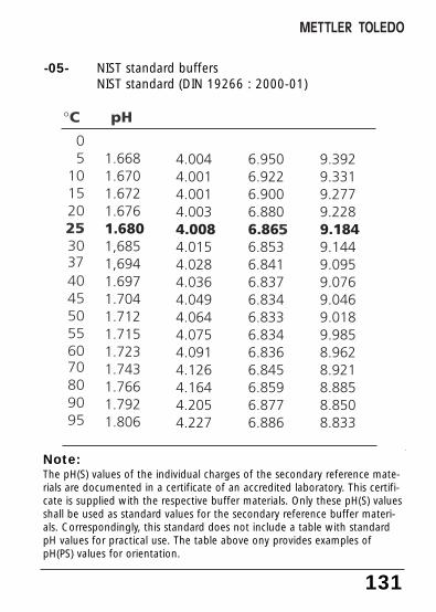
131
-05- NIST standard buffersNIST standard (DIN 19266 : 2000-01)
Note:The pH(S) values of the individual charges of the secondary reference mate-rials are documented in a certificate of an accredited laboratory. This certifi-cate is supplied with the respective buffer materials. Only these pH(S) valuesshall be used as standard values for the secondary reference buffer materi-als. Correspondingly, this standard does not include a table with standardpH values for practical use. The table above ony provides examples ofpH(PS) values for orientation.

132 pH Transmitter 2100e FF
-06- HACH buffersNominal value: 4.00, 7.00, 10.18
°C pH
05
101520253035404550556065707580859095
4.004.004.004.004.004.014.014.024.034.054.064.074.094.094.094.094.094.094.094.09
7.147.107.047.047.027.006.996.986.986.986.986.986.996.996.996.996.996.996.996.99
10.3010.2310.1110.1110.0510.009.969.929.889.859.829.799.769.769.769.769.769.769.769.76
*******
* Values complemented
Buffer values up to 60 °C as specified by Bergmann & BevingProcess AB.
*******
*******
Buffer tables

133
-07- WTW buffers
°C pH
05
101520253035404550556065707580859095
2.032.022.012.002.002.001.991.991.981.981.981.981.981.992.002.002.002.002.002.00
4.014.014.004.004.004.014.014.024.034.044.064.084.104.134.164.194.224.264.304.35
7.127.097.067.047.027.006.996.986.976.976.976.986.986.997.007.027.047.067.097.12
10.6510.5210.3910.2610.1310.009.879.749.619.489.35

134 pH Transmitter 2100e X FF
FM Control Drawing

135
����� ���
�� �� ���� ��� ��� ����� �� ������ ������
�� ����� ������ ���� �� ������������� �� �������� ��� � �� � �� �� ��� �� �� � ����� ������ ��� � ���� �� ��� ������ ����� �� �������� ��� ��� ������������� � �� � ������ !" #$ �� ������ !� # �� �� ���� !% # ����� �������� ��� � �� � �� � � ���� ���� �� �������� ��� �$ �������� � ���$ ��� � &� � �� � �� �� � �� ���� !' $ " $ " #$ �������� !� $ � $ � # �� �� ���� !% # ����� � � � ������� �� �� ��� �� �� � �� !����� ����#��� �������$ �� � ����� ��������� ���� � � � ��� �� !� # �� ������ �� !( # �� �� �� � ��!���� �� � �� ����� ���# ������� �� �� ������ ��� � � �� � �� &� � �� ) �� �� *+ ,-����������� �� ���� ������ ��� ���� �� ���� ����$ ���� ��� �� ��� �� �� � ��$ � ����� �������� �� �� �� ���� ��� �� ������ ���� �� ����� ���� !' $ " $ " # �� �� ��� �� �� � �� �� �� ����� �� �� ��� � ������ �� �� � � �� *. " ���� �� /. " ���� 0������ &������ ������� �� �� �� � �� � �� � � ��$ � ��� �� � �� �� � �� � ��� ����� �� ������ �� � �� �� ���$ ���� �� � 1 ������ �� )+ ,0 ��� �� ������������ �� � ��� ����� &������ �� �� ��� ��� ���� �� ���� �� � �� �������� ��� ������� ������� �� �� � ����� � �� �� �� ���������� �� ���� �� �� ������ ���� �� �������� � � ���2(��� ��� �� 342 *) ��� *)+ 51������� �� �� ���� �� �� (42 +�. ��� * �-51�
� � ��� �� �� ���� �� �� �42 6+ ��� /++ ��51��4 7 �4 ���5��� 8 +�) �4 ���5���$ �� ���� ��� � ��� ��� ���4 7 �4 ���5��� 8 �4 ���5���$ �� �� ��� � ������� �� �� ���(� �� �� ��� � ��2 � �� 9+ �(� �� �� ����1 � ��2 � �� * 1�(� �� �� ����2 � �� * ������ ���0� �� �� �� �� ����1 � �� � ������ ��� ����� ��� ���� �� �������� � � ��� � ��� ��23 7 :+ �� *++� 7 + ��� /�/ ,����� � �� ������ ����� �� � �� ���� ��1 �� ������$ ��� ���$ ������� �� �� � �� ��� � ��������� �� �� ���� � ��� ���������$ �� �� ��� ��� � �����$ �� ������ �� ��� � ��� �� �� �� � �� �� ��� �� � ������� �� ���� ��� ��� �� �� �������� ��� �� ����� �� �����
�� �������� � ��� ������ ������ ���� �� ������������� �� �; 0������ �������� ��� ����� ���� ����� � � ��� ��� ������ ��� � ���� �� ������ ���� ��� ���2' �� " �� " " $ � �� � �� � � � % % � � �� � � 8 � ���� ������ �� � ���� ( �� (� ( 8 ( �� (53 !( 53 �� ( 53 # �� ( 53 !( 53 �� ( 53 #�� �������� � ��� ����� ������ ���� �� ������������� �� �; ������ �������� ��� ����� ���� ����� � � ��� ��� ������ ��� � ���� �� ������ ���� ��� ���2' �� " �� " " $ � �� � �� � � $ % % �<��=�� �� ������� � ��� � �� ��� ��� ��� �� �� �� �� �� ��� ����������������� &������ ������� �� �� 0��� �� 0�� � �� ��� ��� � �� �� � ��� �� �/)+ " �� " ���� �� ���� ����� � �� ����� �� ���� 0���5��0 3%*/�+>�+* !���� �� ��� ) ��� ����� ��� �� ����#�?��� �� ���� �� �������� ��� � � ���� ��� - @ ���� !�� ����# (�� ����A �� �� � ���� �������� � ���B !0���5��%0 C+# ������ )+. �� )+)��� ����� �� ���� �� ��� �� 0�� � �� ��� � �; 0������ ���� �� ��� �� �������0��� �� 0�� � �� � ��� �����4 ��� �� ���� �� ��� ��� � ������� ��� ��� ���� ���&��������� �- /*++ %0$ �� /*++ �� ��� � 0������ ��� �� *$ D�� +$ ����� ����� �� �������� 0�� E��F ��� �� 0�� � �� �� 0�� �� ���� 0�� � �� �� �� �- /*++ %0$ �- /*++ �� ����� ���� ������� � ���� ��� �� ��� �� *$ D�� *$ �� �� *$ D�� /$ �� � ��� ��� �� ��� �� *$D�� + �� �� *$ <������ *$ - @ ���� !�� ����# (�� ������� ������ �� �� ��� ������� ����� �; 0����� � ������ ���������� 0�� � �� � ����� ���� �� � �� ��� �� � ��� �� � *�) "$ +�* 0 �� /) �G�
� � � � �� �� �
� � � �� �
� �� �
� �� � � � � � � � � � � � � � �� � � �� � � � � � �
� �� � � � � � � � � � �
�� ��
I*�
/�
9�.�
)�
>�
C�
6�
:�*+�

136 pH Transmitter 2100e X FF

137
Combinationelectrode
Combination of glass and reference elec-trode in one body.
Asymmetrypotential
Glossary
The voltage which a pH electrode pro-vides at a pH of 7. The asymmetry poten-tial is different for each electrode andchanges with age and wear.
Calimatic Automatic buffer recognition. Before thefirst calibration, the buffer set used mustbe activated once. The patented Calimaticthen automatically recognizes the buffersolutions used during calibration.
Buffer set Contains selected buffer solutions whichcan be used for automatic calibrationwith the Calimatic. The buffer set mustbe selected prior to the first calibration.
Buffer solution Solution with an exactly defined pH valuefor calibrating a pH meter.
Calibration Adjustment of the pH meter to the cur-rent electrode characteristics. The asym-metry potential and slope are adjusted.You can conduct either a one or a two-point calibration. With one-point calibra-tion only the asymmetry potential (zeropoint) is adjusted.

GainCheck Device self-test which runs automaticallyin the background at fixed intervals. Thememory and measured-value transmissionare checked. You can also start theGainCheck manually. Then a display test isalso conducted and the software versiondisplayed.
(Fieldbus Intrinsically Safe Concept)(Fieldbus Non Incendive Concept)Permits connection of several devices to acommon bus line and defines limit valuesfor device and cable parameters. This model developed by the German PTBassumes that only one “active” device, i.e.the bus supply is connected to the fieldbus. All other devices are “passive” withregard to the power supply into the bus.
FISCO modelFNICO model
138 pH Transmitter 2100e FF
Electrode slope
Is indicated in % of the theoretical slope(59.2 mV/pH at 25 °C). The electrodeslope is different for each electrode andchanges with age and wear.
Electrodezero point
See asymmetry potential
ISFET sensor ISFET sensors consist of an ISFET measuringelectrode, a reference electrode, and a tem-perature probe. For additional information, please refer toISFET manual.
Glossary

139
Sensocheck Sensocheck continuously monitors theglass and reference electrodes. The result-ing information is indicated by theSensoface smileys. Sensocheck can beswitched off.
Mode code Preset four-digit number to select certainmodes.
pH electrodesystem
A pH electrode system consists of a glassand a reference electrode. If they are com-bined in one body, they are referred to ascombination electrode.
Responsetime
Time from the start of a calibration stepto the stabilization of the electrode poten-tial.
One-pointcalibration
Calibration with which only the asymme-try potential (zero point) is taken intoaccount. The previous slope value isretained. Only one buffer solution isrequired for a one-point calibration.
Isfet adapter Adapter between Isfet sensor and trans-mitter. Here, the signal of the pH-sensitiveFET is converted to voltage correspondingto the signal of a glass electrode. Thisvoltage is led to the pH input of the trans-mitter and is processed further as usual.The adapter is directly supplied from thetransmitter.

Sensoface Provides information on the electrode con-dition. The zero point, slope, and responsetime are evaluated. In addition, theSensocheck information is indicated.
Slope See electrode slope
Two-pointcalibration
Calibration with which the electrodeasymmetry potential (zero point) and slopeare determined. Two buffer solutions arerequired for two-point calibration.
Zeroadjustment
Basic adjustment of the ISFET sensor toensure reliable Sensoface information.
140 pH Transmitter 2100e FF
Glossary
Zero point See asymmetry potential

141

pH Transmitter 2100e FF142
Index
AAccessories . . . . . . . . . . . . . . . . . . . . . . . . . . . . . . . . . . . 119Alarm LED . . . . . . . . . . . . . . . . . . . . . . . . . . . . . . . . . . . . . 47Alarm settings . . . . . . . . . . . . . . . . . . . . . . . . . . . . . . . . . . 62Alarm via Fieldbus . . . . . . . . . . . . . . . . . . . . . . . . . . . . . . . 87
Alarm handling . . . . . . . . . . . . . . . . . . . . . . . . . . . . .105Analog Input Blocks (AI) . . . . . . . . . . . . . . . . . . . . . . 21, 104
Bus Parameters . . . . . . . . . . . . . . . . . . . . . . . . . . . . . .108Configuration . . . . . . . . . . . . . . . . . . . . . . . . . . . . . . . .24
Assembly . . . . . . . . . . . . . . . . . . . . . . . . . . . . . . . . . . . . . 28Automatic device self-test . . . . . . . . . . . . . . . . . . . . . . . . . 48
BBlock alarms . . . . . . . . . . . . . . . . . . . . . . . . . . . . . . . . . . 105Buffer tables . . . . . . . . . . . . . . . . . . . . . . . . . . . . . . . . . . 127Bus address . . . . . . . . . . . . . . . . . . . . . . . . . . . . . . . . . . . . 65Bus communication . . . . . . . . . . . . . . . . . . . . . . . . . . . . . 18Bus parameters . . . . . . . . . . . . . . . . . . . . . . . . . . . . . . . . . 88
Adjusting bus address on the device . . . . . . . . . . . . . .65Analog Input Blocks . . . . . . . . . . . . . . . . . . . . . . . . . .108Resource Block . . . . . . . . . . . . . . . . . . . . . . . . . . . . . . .88Standard Transducer Block . . . . .92, 94, 96, 98, 100, 102
CCalibration on the device . . . . . . . . . . . . . . . . . . . . . . . . . 66
Automatic calibration with Calimatic . . . . . . . . . . . . . .70Calibration interval . . . . . . . . . . . . . . . . . . . . . . . . .61, 85Calibration mode . . . . . . . . . . . . . . . . . . . . . . . . . . . . .61Data entry of premeasured electrodes . . . . . . . . . . . . .74Display of calibration data . . . . . . . . . . . . . . . . . . . . . .83Error messages . . . . . . . . . . . . . . . . . . . . . . . . . . . .81-82ISFET sensors . . . . . . . . . . . . . . . . . . . . . . . . . . . . . . . .67Manual calibration . . . . . . . . . . . . . . . . . . . . . . . . . . . .72ORP calibration . . . . . . . . . . . . . . . . . . . . . . . . . . . . . . .78

143
Product calibration . . . . . . . . . . . . . . . . . . . . . . . . . . . .76Temp probe adjustment . . . . . . . . . . . . . . . . . . . . . . . .80Zero adjustment . . . . . . . . . . . . . . . . . . . . . . . . . . . . . .68
Calibration via Fieldbus . . . . . . . . . . . . . . . . . . . . . . . . . . . 90Calimatic . . . . . . . . . . . . . . . . . . . . . . . . . . . . . . . . . . . . . 70CFF-File . . . . . . . . . . . . . . . . . . . . . . . . . . . . . . . . . . . . . . . 28CHANNEL parameter . . . . . . . . . . . . . . . . . . . . . . . . 24, 104Cleaning . . . . . . . . . . . . . . . . . . . . . . . . . . . . . . . . . . . . . . 85Commissioning and configuration via Foundation Fieldbus 22Communication Fieldbus / Device . . . . . . . . . . . . . . . . . . . 86Communication model . . . . . . . . . . . . . . . . . . . . . . . 20, 122Configuration on the device . . . . . . . . . . . . . . . . . . . . . . . 50
Alarm settings . . . . . . . . . . . . . . . . . . . . . . . . . . . . . . .62Bus address . . . . . . . . . . . . . . . . . . . . . . . . . . . . . . . . .64Calibration mode and solution . . . . . . . . . . . . . . . . . . .60Electrode type . . . . . . . . . . . . . . . . . . . . . . . . . . . . . . .54Factory settings . . . . . . . . . . . . . . . . . . . . . . . . . . . . . .52Individual settings . . . . . . . . . . . . . . . . . . . . . . . . . . . . .53Menu structure . . . . . . . . . . . . . . . . . . . . . . . . . . . . . .51TC process medium . . . . . . . . . . . . . . . . . . . . . . . . . . .58Temp detection for meas/cal . . . . . . . . . . . . . . . . . . . . .58Temperature unit and probe . . . . . . . . . . . . . . . . . . . . .56Variable/unit . . . . . . . . . . . . . . . . . . . . . . . . . . . . . . . . .54
Configuration via Fieldbus . . . . . . . . . . . . . . . . . . . . . 22, 90Connection . . . . . . . . . . . . . . . . . . . . . . . . . . . . . . . . . . . . 32
VP cable . . . . . . . . . . . . . . . . . . . . . . . . . . . . . . . . . . . .34Connection to supply and coupling elements . . . . . . . . . . . 8Cyclic measured value status . . . . . . . . . . . . . . . . . . . . . . 110
DDevice description . . . . . . . . . . . . . . . . . . . . . . . . . . . 22, 119Device Identifier . . . . . . . . . . . . . . . . . . . . . . . . . . . . . . . . 23Device registration . . . . . . . . . . . . . . . . . . . . . . . . . . . . . . 17Diagnostics functions . . . . . . . . . . . . . . . . . . . . . . . . . . . . 83

144 pH Transmitter 2100e FF
Index
Display . . . . . . . . . . . . . . . . . . . . . . . . . . . . . . . . . . . . . . . 45Disposal . . . . . . . . . . . . . . . . . . . . . . . . . . . . . . . . . . . . . . . 2Division 2 wiring . . . . . . . . . . . . . . . . . . . . . . . . . . . . . . . 124
EEC Declaration of Conformity . . . . . . . . . . . . . . . . . . . . . . 11EC-Type-Examination Certificate . . . . . . . . . . . . . . . . . . . . 12EMC . . . . . . . . . . . . . . . . . . . . . . . . . . . . . . . . . . . . . . . . 123Error messages . . . . . . . . . . . . . . . . . . . . . . . . . . . . 114, 116
Calibration error messages . . . . . . . . . . . . . . . . . . . . . .81Display of last error message . . . . . . . . . . . . . . . . . . . .83LAST_ERROR parameter . . . . . . . . . . . . . . . . . . . . . . . .91
Explosion protection . . . . . . . . . . . . . . . . . . . . . . . . . . . . 123Cleaning in a hazardous location . . . . . . . . . . . . . . . . . .8
FFISCO model . . . . . . . . . . . . . . . . . . . . . . . . . . . . . . . . . . 135FM Control Drawing . . . . . . . . . . . . . . . . . . . . . . . . . . . . 134FNICO model . . . . . . . . . . . . . . . . . . . . . . . . . . . . . . . . . 135Foundation Fieldbus . . . . . . . . . . . . . . . . . . . . . . . . . . . . . 18
Basic properties . . . . . . . . . . . . . . . . . . . . . . . . . . . . . .18Device registration . . . . . . . . . . . . . . . . . . . . . . . . . . . .17
Function blocks . . . . . . . . . . . . . . . . . . . . . . . . . . . . . . . . . 21
GGainCheck device self test . . . . . . . . . . . . . . . . . . . . . . . . 48Glossary . . . . . . . . . . . . . . . . . . . . . . . . . . . . . . . . . . . . . 134
HHold mode . . . . . . . . . . . . . . . . . . . . . . . . . . . . . . . . . . . . 47
LED in Hold mode . . . . . . . . . . . . . . . . . . . . . . . . . . . .63
IInstallation . . . . . . . . . . . . . . . . . . . . . . . . . . . . . . . . . . . . 32Intellectual Property Rights . . . . . . . . . . . . . . . . . . . . 125-126Intended use . . . . . . . . . . . . . . . . . . . . . . . . . . . . . . . . . . . . 9

ISFET sensor . . . . . . . . . . . . . . . . . . . . . . . . . . . . . . . . . . 135Calibration . . . . . . . . . . . . . . . . . . . . . . . . . . . . . . . . . .67Wiring . . . . . . . . . . . . . . . . . . . . . . . . . . . . . . . . . . . . .41
KKey lock . . . . . . . . . . . . . . . . . . . . . . . . . . . . . . . . . . . . . . 86Keypad . . . . . . . . . . . . . . . . . . . . . . . . . . . . . . . . . . . . . . . 46
LLimit alarms . . . . . . . . . . . . . . . . . . . . . . . . . . . . . . . . . . 105Linearization types . . . . . . . . . . . . . . . . . . . . . . . . . . . . . 104
MMeasured value status . . . . . . . . . . . . . . . . . . 112, 114, 116
Cyclic . . . . . . . . . . . . . . . . . . . . . . . . . . . . . . . . . . . . .110Measurement . . . . . . . . . . . . . . . . . . . . . . . . . . . . . . . . . . 82Mode codes . . . . . . . . . . . . . . . . . . . . . . . . . . . . . . . . . . . 49Mounting plan . . . . . . . . . . . . . . . . . . . . . . . . . . . . . . . . . 29
OOperating mode . . . . . . . . . . . . . . . . . . . . . . . . . . . . . . . 104Operating states . . . . . . . . . . . . . . . . . . . . . . . . . . . . . . . 112ORP calibration . . . . . . . . . . . . . . . . . . . . . . . . . . . . . . . . . 78ORP measurement . . . . . . . . . . . . . . . . . . . . . . . . . . . . . . 55OUT_SCALE parameter . . . . . . . . . . . . . . . . . . . 24, 104, 108Overview . . . . . . . . . . . . . . . . . . . . . . . . . . . . . . . . . . . . . 27
PPacking list . . . . . . . . . . . . . . . . . . . . . . . . . . . . . . . . . . . . 28Panel-mount kit . . . . . . . . . . . . . . . . . . . . . . . . . . . . . . . . 31Parameter set for copy . . . . . . . . . . . . . . . . . . . . . . . . . . . 53Patents . . . . . . . . . . . . . . . . . . . . . . . . . . . . . . . . . . 125-126pH calibration . . . . . . . . . . . . . . . . . . . . . . . . . . . . . . . . . . 67Pipe-mount kit . . . . . . . . . . . . . . . . . . . . . . . . . . . . . . . . . 30Process variable selection . . . . . . . . . . . . . . . . . . . . . . . . 104Product calibration on the device . . . . . . . . . . . . . . . . . . . 76
145

146 pH Transmitter 2100e FF
Index
Product calibration via Fieldbus . . . . . . . . . . . . . . . . . . . . . 90Product line . . . . . . . . . . . . . . . . . . . . . . . . . . . . . . . . . . 119Protective hood . . . . . . . . . . . . . . . . . . . . . . . . . . . . . . . . . 30
RResource block (RB) . . . . . . . . . . . . . . . . . . . . . . . . . . 21, 86
Bus parameters . . . . . . . . . . . . . . . . . . . . . . . . . . . . . .88Configuration . . . . . . . . . . . . . . . . . . . . . . . . . . . . . . . .23
Return of products . . . . . . . . . . . . . . . . . . . . . . . . . . . . . . . 2
SSafety functions . . . . . . . . . . . . . . . . . . . . . . . . . . . . . . . . 47Safety information . . . . . . . . . . . . . . . . . . . . . . . . . . . . . . . 7
Installation . . . . . . . . . . . . . . . . . . . . . . . . . . . . . . . . . . . 8Sensocheck . . . . . . . . . . . . . . . . . . . . . . . . . . . . . . . . . 48, 84
ON / OFF . . . . . . . . . . . . . . . . . . . . . . . . . . . . . . . . . . .63Sensoface . . . . . . . . . . . . . . . . . . . . . . . . . . . . . . . . . . 48, 84
Evaluation limits . . . . . . . . . . . . . . . . . . . . . . . . . . . . . .85Sensor monitor . . . . . . . . . . . . . . . . . . . . . . . . . . . . . . . . . 83Short description . . . . . . . . . . . . . . . . . . . . . . . . . . . . . . . . . 9Specifications . . . . . . . . . . . . . . . . . . . . . . . . . . . . . . . . . 120System configuration . . . . . . . . . . . . . . . . . . . . . . . . . . . . 25
TTable of contents . . . . . . . . . . . . . . . . . . . . . . . . . . . . . . . . 3Temp probe adjustment . . . . . . . . . . . . . . . . . . . . . . . . . . 80Terminal assignments . . . . . . . . . . . . . . . . . . . . . . . . . . . . 32Trademarks . . . . . . . . . . . . . . . . . . . . . . . . . . . . . . . . . . . . 10Transducer Block (TB) . . . . . . . . . . . . . . . . . . . . . . . . . 21, 90
Bus parameters . . . . . . . . . . . . . . . . . . . . . . . . . . . . . .92
UUser interface . . . . . . . . . . . . . . . . . . . . . . . . . . . . . . . . . . 44
V

147
VP cable . . . . . . . . . . . . . . . . . . . . . . . . . . . . . . . . . . . . . . 34
WWarranty . . . . . . . . . . . . . . . . . . . . . . . . . . . . . . . . . . . . . . . 2Wiring example ORP . . . . . . . . . . . . . . . . . . . . . . . . . . . . . 42Wiring examples pH . . . . . . . . . . . . . . . . . . . . . . . . . . . . . 36
ISFET sensor . . . . . . . . . . . . . . . . . . . . . . . . . . . . . . . . .41pH/ORP simultaneous . . . . . . . . . . . . . . . . . . . .37-38, 40VP connection . . . . . . . . . . . . . . . . . . . . . . . . . . . . .36-38
Write protection . . . . . . . . . . . . . . . . . . . . . . . . . . . . . . . . 86
XXD_SCALE parameter . . . . . . . . . . . . . . . . . . . . 24, 104, 108
ZZero adjustment . . . . . . . . . . . . . . . . . . . . . . . . . . . . . . . . 68

TA-194.171-MTE02 120705 Software version 1.x
Mettler-Toledo GmbH, Process AnalyticsIndustrie Nord, CH-8902 Urdorf, SwitzerlandPhone + 41 44 736 22 11, Fax +41 44 736 26 36
Subject to technical changes.© Mettler-Toledo GmbH, Process Analytics07/05 Printed in Switzerland. 52 121 251