Embed Size (px)
Citation preview
S0814MS07
Instruction Manual Cyclone Catcher with Sludge Tank
C-Jaguar
Warning ◆ This apparatus is designed to filter a water-soluble
grinding fluid, a wire-cut EDM (electric discharge machining) fluid, etc. Do not use this apparatus for any other purpose.
◆ Read this Instruction Manual carefully and understand the descriptions before operating this apparatus or performing maintenance/inspection work.
◆ Store this Instruction Manual carefully so that you can review it whenever operating this apparatus or performing maintenance/inspection work.
Contents 1. Safety Precautions ·················································· 1 2. Introduction ··························································· 2 3. Unpacking Check···················································· 2 4. Installation ···························································· 2 5. Operation ······························································ 4 6. Maintenance and Inspection ····································· 5 7. Troubleshooting······················································ 7 8. Replacement of ADAPTER ······································· 8 9. Replacement of Ball valve with actuator (SV2) ········· 10 10. Repair and Warranty ··········································· 12
Attachments
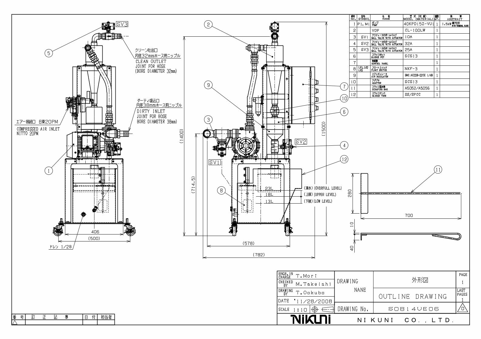
Outline Drawing, Flow Chart, Control Panel Outline Drawing, Electrical Diagram, Timing Diagram, VDF Instruction Manual, Pump Instruction Manual
Nikuni Co., Ltd. 843-5 Kuji, Takatsu-ku, Kawasaki City, Kanagawa JAPAN 213-0032 TEL: +81-44-833-1121 (Main Switchboard)

S0814MS07
1
1. Safety Precautions In this Instruction Manual, safety precautions are divided into “Warning” and “Caution” according to level to allow you to use the product safely and properly and prevent harm and damage to the user and others in the area.
Warning Failure to observe the indicated warning could result in death or serious injury of the user or others in the area. Understand the descriptions fully and follow the instructions without fail.
Caution
Failure to observe the indicated caution could result in impairment of the user or others in the area or property damage. Understand the descriptions fully and follow the instructions without fail.
The following symbols are also used with those shown above to allow for normal operation and prevent a reduction in the product life and failures. Be sure to follow the instructions.
Prohibited Indicates what you must not do.
Forced Indicates what you are forced to do.
Warning ◆ Carry out wiring work properly according to the Technical Standards on
Electrical Equipment and Indoor Wiring Regulations. Incorrect wiring work may result in electric shocks or fire.
◆ Before maintenance, inspection or part replacement, turn off the source power. Failure to do so may result in electric shocks, or personal injury due to accidental starting of the machine.
◆ Establish a ground securely. Failure to do so may result in electric shocks during a machine failure or short-circuit.
◆ Do not open the switch box or the motor terminal box unnecessarily. Doing so may result in electric shocks.
◆ Do not splash water on live parts. Doing so may result in a short circuit, electric shocks or a machine failure.
Caution ◆ This apparatus is designed to filter a water-soluble grinding fluid, a wire-cut
EDM fluid, etc. Do not use this apparatus for any other purpose. ◆ Do not move or carry piping or equipment by hand. Doing so may result not only
in property damage but also in personal injury. ◆ Do not touch the motor or pump during or immediately after operation. Doing so
may result in burns due to high temperature. ◆ Do not cover the motor with a blanket or cloth. Doing so may result in ignition by
overheating.

S0814MS07
2
2. Introduction 2-1. This apparatus is a unit that uses VDF(Vortex Dynamic Filter) compatible with a
water-soluble grinding fluid and a wire-cut EDM fluid. Consult us when using any fluid other than the above.
2-2. When any work material with a specific gravity of 2.5 or less is used, filtration efficiency decreases due to the property of VDF. Consult us when using any work material with a lower specific gravity.
2-3. Use the apparatus while the height from the coolant tank fluid level to the pump inlet port is within one meter.
Caution ◆ This apparatus is designed to filter a water-soluble grinding fluid, a wire-cut
EDM fluid, etc. Do not use this apparatus for any other purpose. Doing so may result in unexpected accidents or personal injury.
3. Unpacking Check After receiving the apparatus, check the following: 1. Check that the product is as per order with the Delivery Specification. 2. Check that the product is not damaged and the bolts/nuts have not come loose during
transport. 3. Check that accessories are all supplied. 4. In the case of any defective condition, contact your dealer by specifying the product model
and serial number described on the nameplate.
4. Installation 4-1.Apparatus movement and carriage
When moving or carrying the apparatus, lift the stand with a forklift etc. The apparatus is unstable since its center of gravity is high. Therefore, move or carry the apparatus carefully to prevent it from falling down.
Caution ◆ Do not move or carry the apparatus in an unstable condition. Doing so may result
not only in apparatus damage but also in personal injury.
4-2.Installation
1) This apparatus is designed for inside installation. Install it above the working fluid tank or on the periphery of the tank of a machine tool.
2) Avoid the suction piping of the apparatus from sucking in fluid from sludge accumulated places, extremely contaminated tanks or places where sludge of more than 150μm is mixed.
3) Secure maintenance space as well as space for piping and wiring connections around this apparatus.
Avoid the suction piping of the apparatus from sucking in fluid from sludge accumulated places, extremely contaminated tanks or places where sludge of more than 150μm is mixed.
S0814MS07
3
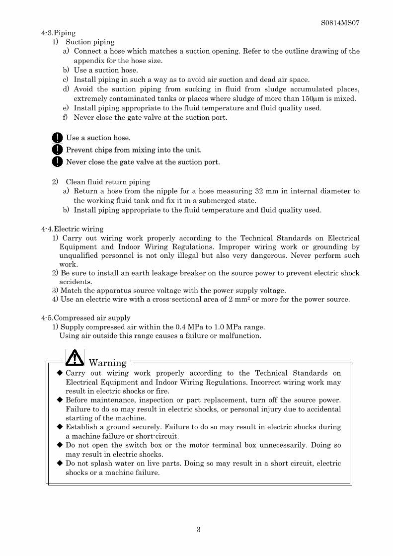
4-3.Piping 1) Suction piping
a) Connect a hose which matches a suction opening. Refer to the outline drawing of the appendix for the hose size.
b) Use a suction hose. c) Install piping in such a way as to avoid air suction and dead air space. d) Avoid the suction piping from sucking in fluid from sludge accumulated places,
extremely contaminated tanks or places where sludge of more than 150μm is mixed. e) Install piping appropriate to the fluid temperature and fluid quality used. f) Never close the gate valve at the suction port.
Use a suction hose. Prevent chips from mixing into the unit. Never close the gate valve at the suction port. 2) Clean fluid return piping
a) Return a hose from the nipple for a hose measuring 32 mm in internal diameter to the working fluid tank and fix it in a submerged state.
b) Install piping appropriate to the fluid temperature and fluid quality used. 4-4.Electric wiring
1) Carry out wiring work properly according to the Technical Standards on Electrical Equipment and Indoor Wiring Regulations. Improper wiring work or grounding by unqualified personnel is not only illegal but also very dangerous. Never perform such work.
2) Be sure to install an earth leakage breaker on the source power to prevent electric shock accidents.
3) Match the apparatus source voltage with the power supply voltage. 4) Use an electric wire with a cross-sectional area of 2 mm2 or more for the power source.
4-5.Compressed air supply
1) Supply compressed air within the 0.4 MPa to 1.0 MPa range. Using air outside this range causes a failure or malfunction.
Warning ◆ Carry out wiring work properly according to the Technical Standards on
Electrical Equipment and Indoor Wiring Regulations. Incorrect wiring work may result in electric shocks or fire.
◆ Before maintenance, inspection or part replacement, turn off the source power. Failure to do so may result in electric shocks, or personal injury due to accidental starting of the machine.
◆ Establish a ground securely. Failure to do so may result in electric shocks during a machine failure or short-circuit.
◆ Do not open the switch box or the motor terminal box unnecessarily. Doing so may result in electric shocks.
◆ Do not splash water on live parts. Doing so may result in a short circuit, electric shocks or a machine failure.

S0814MS07
4
5. Operation 5-1.Operation preparation
1) Recheck that installation, wiring and piping are properly executed. 2) Feed fresh water or the working fluid used to the “UPPER LEVEL” of the FLOAT
SWITCH. 3) Turn the shaft lightly with a flat-blade screwdriver from the rear of the cyclone pump
motor to check that movement is not slow or nonuniform. 4) Prime the pump from the priming cup. After removing the plug from the priming cup,
prime the pump with fresh water or the working fluid used until the pump is filled to capacity and tighten the plug.
5) Set the change-over switch CONVEVER (COS2) to AUTO. 6) Turn on COS1 and turn on/off the earth leakage breaker (ELB) to visually check from
the rear of the cyclone pump motor that the pump rotation direction (clockwise rotation) is proper when seen from the motor side. After checking it, turn off the ELB.
7) Before reversing the rotation direction, turn off the power temporarily and interchange 2 out of 3 electric wires. Check the rotation direction by inching.
8) Turn on the ELB and turn on COS1. 9) Check that the fluid starts to flow from the clean fluid return piping and the pressure
gauge indicates 0.15 MPa or more. After operation start, open SV2 to start fluid supply to the sludge tank. When the fluid level reaches the upper limit, close SV2 and open SV3.
10) Check that there is no fluid leak from the piping and the sludge tank. 11) Turn off the ELB to stop it.
Stopping COS1 enters a cycle stop and the pump stops after completion of one cycle.
Do not run the pump at idle (dry operation), since doing so causes a failure. Do not run the pump by reversing the rotation direction, since doing so causes
a failure. Prime the pump with reliability. Insufficient priming may not pump fluid up. After inspecting or cleaning the pump, tank, etc., be sure to prime the pump.

S0814MS07
5
5-2.Operation 1) Recheck that installation, piping and wiring are properly executed. 2) Turn on the ELB. The power lamp (WL1) lights up. 3) In the case of COS1 operation or external operation signal ON, turn on IN1 and 0V.
With the pump starting, operation starts. 4) Repeated automatic operation is performed by taking the pump operation filtration start,
tank supernatant discharge and sludge pot concentrate discharge as one cycle. Refer to the Timing Diagram to check operation.
5) The setting of the precipitation time timer can be changed with T1 in the operation panel. (Initial set value: 30 min.) If the sludge concentration in dirty fluid is high, the cyclone body or piping may be clogged with significantly accumulated sludge in a sludge pot. In that case, set the precipitation time timer (T1) for a shorter time.
6) Stopping COS1 or turning off the external operation signal makes pump operation (GL1) flash and enters a cycle stop. The pump stops and GL1 goes out after completion of one cycle. Turn off the power after a cycle stop has been completed. Turning off the power during a cycle stop causes piping clogging or a failure due to disabled sludge pot concentrate discharge.
Do not run the pump at idle (dry operation), since doing so causes a failure. Do not run the pump by reversing the rotation direction, since doing so causes
a failure. Turn off the power after a cycle stop has been completed. Failure to do so may cause sludge pot clogging due to disabled sludge pot
concentrate discharge.
6. Maintenance
6-1.Maintenance Inspect this apparatus periodically to prevent troubles from occurring under the influence of the operating environment such as the temperature, humidity and dust or due to secular change or life of the part used.
Periodic Inspection Table
Inspection Item Evaluation Standard Frequency Supply pressure low 0.15 MPa or more Within every 1 monthWater leak from pump mechanical seal Leak rate: 10 cc/hr. or less Within every 1 month
Motor bearing temperature Room temperature: +40°C or 75°C or less Within every 1 monthWiring damage No damage Within every 1 monthCurrent value Not to exceed rated current Within every 1 monthEarth leakage breaker operation Normal operation Within every 1 monthThermal relay operation Normal operation Within every 1 monthIndicator lamp indication Normal indication Within every 1 monthPressure switch set value According to set value in attached table Within every 1 monthTimer set value According to set value in attached table Within every 1 monthAir regulator setting According to set value in attached table Within every 1 monthTightening of each bolt Tightened securely Within every 1 monthADAPTER Not worn out Within every 1 monthSV2 Not worn out Within every 1 month

S0814MS07
6
List of Set Values Symbol Name Application Installation Place Initial Setting Current Setting
T1 Timer Precipitating time setting
In operation panel 30 min min
PS Pressure switch
Air pressure error detection Tank body 0.3 MPa MPa
– Air regulator Air pressure adjustment Tank body 0.4 MPa MPa
Each setting of the timer (T1) can be changed. When changing its setting, consider the following tendencies: - When a longer T1 time is set, a longer precipitation time is taken and the concentration
amount in a sludge pot becomes larger. - When a shorter T1 time is set, a shorter precipitation time is taken and the concentration
amount in a sludge pot becomes smaller. Please take note that setting a longer T1 time to make the concentration amount in a sludge pot larger may clog piping or the sludge pot.
If you have any questions about the setting, contact us.
Warning ◆ Before performing an overhaul, turn off the source power and check that electric
current is not passed. Failure to do so may result in personal injury due to accidental starting of the machine.
◆ Before performing control panel maintenance/inspection or part replacement, turn off the source power and check that electric current is not passed. Failure to do so may result in electric shocks.
6-2. Notes when stopping for a long term 1) The pump and piping might be damaged by freezing the liquid for a short stop period
to say nothing of time when driving is stopped for a long term in winter etc. Please put out the liquids that exist in the tank and piping. Or, please warm the liquid.
2) Please do not generate rust at finished surface in the bearing etc. Please turn the axis edge of the pump motor once a month.
3) Please put out the liquids when you use the liquid that the conveyer might rust.

S0814MS07
7
7. Troubleshooting
When an error occurs, indicator lamps on the operation panel surface (RL1 to RL4) light up. In the case of an error occurrence, find out the cause and take measures against it immediately. To restart the apparatus, remove the cause and press the reset button (PBS2). If the error does not fall under any in the table below or a part is damaged, contact your dealer or us.
Indicator Lamp Name Probable Cause Remedy
Overload (RL1)
- Piping or VDF clogging - Malfunction of actuator valve - Overload operation of motor - Foreign matter caught in pump - Too large specific gravity or viscosity
of fluid - Open-phase operation - Voltage reduction
- Clean it. - Replace the part. - Request the manufacturer to
repair it. - Request the manufacturer to
repair it. - Review the plan. - Repair or replace equipment.- Check the voltage.
Full capacity (RL2)
- Apparatus filled to capacity with cleaning fluid
- Contamination of FLOAT SWITCH - FLOAT SWITCH breakdown
- Drain the cleaning fluid. - Clean the part. - Replace the part.
Fluid discharge error (RL3)
- Clogging of piping - Malfunction of actuator valve - Contamination of FLOAT SWITCH - FLOAT SWITCH breakdown
- Clean it. - Replace the part. - Clean the part. - Replace the part.
Air pressure low (RL4)
- Insufficient source pressure - Pressure switch (PS) setting failure
or breakdown - Air regulator setting failure or
breakdown
- Check the source pressure. - Readjust or replace it. - Readjust or replace it.
Pressure value
- Suction piping clogging - Worn impeller out - Please refer to the pump instruction
manual.
- Clean it. - Replace the part.
There is no influence in the sludge elimination factor even if the pressure gauge display becomes 0.15MPa or less. However, please take note that clean flowing quantity decreases.
Warning ◆ Before performing an overhaul, turn off the source power and check that electric
current is not passed. Failure to do so may result in personal injury due to accidental starting of the machine.
◆ Before performing control panel maintenance/inspection or part replacement, turn off the source power and check that electric current is not passed. Failure to do so may result in electric shocks.

S0814MS07
8
8. The exchange method of ADAPTER ADAPTER in the union which has piped VDF is worn out according to an operating condition. The protection effect over Ball valve with actuator (SV2) may be lost. It exchanges, when having worn ADAPTER out in the case of a scheduled inspection. The order of “ADAPTER” is asked to our company. The following tools are prepared for clearing work. ・Pipe wrench (range of use : 10 ~54mm) ・Motor wrench ・Adjustable wrench
In the case of clearing work, shut off the power of supply. Working gloves are worn so that it may not be injured. 8-1. Exchange method 1) Drain the liquid in the main part of the sludge tank from the drain beforehand.
Stop compressed air supply and check in meter that the air in a unit has fallen out completely. Turn the shaft in the actuator portion of SV2, open a valve, and drain the liquid in a VDF and a Sludge-pot.
2) A union is removed and ADAPTER is taken out. 3) A union is fastened after putting new ADAPTER into a union. 4) Connect an air tube as the following "electromagnetic valve - actuator connection table". 5) Supply compressed air, check whether supply pressure is 0.4 MPa, and switch on a power
supply. 6) Resume operation and check that there is no liquid leak from piping.
Warning ◆ Put packing into a union and pipe it certainly. Otherwise, a possibility of causing a liquid leak is during operation.

S0814MS07
9
Union
SV2
Air meter
Actuator
Electromagnetic valve SV1 SV2 SV3
A O O O Port
B S S S
Electromagnetic valve - actuator connection
Air tube
Adapter
Sludge-pot
Long nipple
Drain

S0814MS07
10
9. Replacement of Ball valve with actuator ( SV2) Ball valve with actuator (SV2) is worn out according to an operating condition, and a liquid
leak arises. Then RL2 (OVER FULL) blinks. Then “SV2” is exchanged. When there are many amounts of liquid leaks, RL2 is changed to lighting from blink and
becomes a “Full-of-water alarm”. The order of “SV2” is asked to our company. The following tools are prepared for clearing work. ・Pipe wrench (range of use : 10 ~54mm) ・Motor wrench
・Adjustable wrench In the case of clearing work, shut off the power of supply. Working gloves are worn so that it may not be injured.
9-1. Exchange method 1) Drain the liquid in the main part of the sludge tank from the drain beforehand.
Stop compressed air supply and check in meter that the air in a unit has fallen out completely. Turn the shaft in the actuator portion of SV2, open a valve, and drain the liquid in a VDF and a sludge-pot.
2) Draw out the air tube linked to an actuator. 3) Remove SV2 and a long nipple after removing a union. Remove the sludge which has
collected in the sludge-pot or the long nipple. 4) Attach a long nipple and new SV2 and connect a union. At this time, be sure to rewind a
tape seal, pipe certainly. Put packing into a union and pipe it certainly. 5) Connect an air tube as the following "electromagnetic valve - actuator connection table". 6) Supply compressed air, check whether supply pressure is 0.4 MPa, and switch on a power
supply. 7) Resume operation and check that there is no liquid leak from piping.
Warning ◆ Be sure to roll a tape seal and to pipe certainly, when you pipe.
Put packing into a union and pipe it certainly. Otherwise, a possibility of causing a liquid leak is during operation.

S0814MS07
11
Shaft
Actuator
Air tube
Long nipple Union
SV2
Air meter
Sludge-pot
Drain
Electromagnetic valve SV1 SV2 SV3
A O O O Port
B S S S
Electromagnetic valve - actuator connection

S0814MS07
12
10. Repair and Warranty For repair and maintenance of your purchased product, contact your dealer or us. We shall repair the product at no charge under the conditions shown below. However, the warranty of this product is limited to use within Japan. 1.The warranty term of this product shall be one year after the final acceptance. 2.Where the product becomes faulty or damaged due to a defect in our workmanship in spite of your normal use during the warranty term, we shall repair the faulty/damaged part of this product at no charge. In this case, we shall bear the expenses for repair parts and engineer dispatching but be exempted from other expenses. 3. However, the following failures/damages and consumables will be repaired or replaced at
charge: 1) Failures/damages occurring after the termination of the warranty term 2) Failures/damages resulting from abnormal use or storage 3) Failures/damages resulting from disasters or force meajure such as fire, natural
disasters and acts of God 4) Failures/damages occurring where a part is replaced by the user 5) Failures/damages resulting from repair or modification by the user * Consumables are parts for which wear and tear is expected from the beginning, such as
packing, O-rings, mechanical seals and bearings. 4. We shall not compensate for various expenditures and other damages resulting from
failures occurring during the use of this product. When any abnormal condition is detected during the use of this product, inspect it by referring to “7. Troubleshooting” to determine whether the product is faulty or not. In the case of a failure, contact us immediately. At that time, inform us of the product model and serial number described on the nameplate as well as the failure (error) conditions.
If you have any questions or comments about your purchased product, feel free to contact us. For inquiries:
Nikuni Co., Ltd.
Head Office: 843-5 Kuji, Takatsu-ku, Kawasaki City, Kanagawa JAPAN 213-0032 TEL: +81-44-833-1121 (Main Switchboard), FAX: +81-44-822-1115
Osaka Office: 1-7-10 Doshou-machi, Chuo-ku, Osaka City, Osaka JAPAN 541-0045 TEL: +81-6-6205-7001 (Main Switchboard), FAX: +81-6-6205-7031
Nagoya Office: 4-15-3 Imaike, Chikusa-ku, Nagoya City, Aichi JAPAN 464-0850 TEL: +81-52-741-7301, Fax: +81-52-741-7303
Nagano Office: 1920 Yoshikawanomizo, Matsumoto City, Nagano JAPAN 399-0003 TEL: +81-0263-85-1330, FAX: +81-0263-85-1332
N I K U N I C O . , L T D .

株 式 会 社

N I K U N I C O . , L T D .

C-Jaguar Operating Panel
N I K U N I C O . , L T D .

N I K U N I C O . , L T D .

N I K U N I C O . , L T D .

N I K U N I C O . , L T D .

N I K U N I C O . , L T D .

Ooeration commandCOS1 or IN1
Precipitation time timerT1
PumpP1(M1)
Supernatant discharge valve(SV1)
VDF dirty valve(SV2)
VDF clean valve(SV3)
Fluid level upper limit detection(LS2)
Fluid level lower limit detection(LS3)
Stop
Initial set value
30min 30min
※4
※2
※3 ※3※3
※1
※3
Timing Diagram
S0814FO02
N I K U N I C O . , L T D .
Fluid level lower limit detection
Fluid level upper limit detection
VDF dirty valve
Supernatant discharge valve
VDF clean valve
Pump
Precipitation time timer
Ooeration command
Supernatantdischarge
Concentratedischarge Operation start:Filtration
One cycle
dischargeSupernatant Concentrate
discharge
Cyc
le
sto
p
StopSupernatantdischarge
Concentratedischarge Operation start:Filtration
One cycle
dischargeSupernatant Concentrate
discharge
※1.Basic operations in one cycle are as follows:
『clean fluid supply + sludge precipitation → clean fluid supply
→ clean fluid supply + supernatant discharge → concentrate dischage SV2 open/close
※2.If the fluid level has not reached the upper limit as starting time,open SV2 and
supply fluid to the tank
※3.If the supernatant discharge time (SV1 open time) of 3 min. or longer has elapsed, a RL3
fluid discharge error occurs.
※4.COS1 or IN1 stops after completion of one cycle.
※ Refer to the Timing Diagram together with the Flow Chart.
Supplementary Information


![Dark Silicon & Modern Computer Architecturehtseng/classes/cse203_2019fa/...Data Read Data 1 Read Data 2 m ux 0 1 Instruction [9:5] Instruction [20:16] Instruction[4:0] Sign-extend](https://img.pdfslide.net/doc/110x75/5f427e528f6dcc00ab41727b/dark-silicon-modern-computer-architecture-htsengclassescse2032019fa.jpg)