Embed Size (px)
Citation preview

Great Planes® Model Manufacturing Co. guarantees this kit tobe free from defects in both material and workmanship at the dateof purchase. This warranty does not cover any component partsdamaged by use or modification. In no case shall Great Planes’liability exceed the original cost of the purchased kit. Further,Great Planes reserves the right to change or modify this warrantywithout notice.
In that Great Planes has no control over the final assembly ormaterial used for final assembly, no liability shall be assumed noraccepted for any damage resulting from the use by the user of thefinal user-assembled product. By the act of using the user-assembled product, the user accepts all resulting liability.
If the buyer is not prepared to accept the liability associatedwith the use of this product, the buyer is advised to returnthis kit immediately in new and unused condition to the placeof purchase.
To make a warranty claim, sendthe defective part or item toHobby Services at this address.
Include a letter stating your name, return shipping address, asmuch contact information as possible (daytime telephone number,fax number, e-mail address), a detailed description of the problemand a photocopy of the purchase receipt. Upon receipt of thepackage the problem will be evaluated as quickly as possible.
READ THIS MANUAL BEFORE STARTINGCONSTRUCTION. IT CONTAINS IMPORTANTINSTRUCTIONS AND WARNINGS CONCERNING THE ASSEMBLY AND USE OF THIS MODEL.
GPMZ0295 for GPMA1350 V1Entire Contents © Copyright 2004
Champaign, IllinoisTelephone: (217) 398-8970 ext. 5
INSTRUCTION MANUAL
WARRANTY
Hobby Services3002 N. Apollo Dr. Suite 1
Champaign IL 61822USA
Wingspan: Top Wing: 71.5 in [1815mm] Bottom Wing: 69 in [1755mm]
Wing Area: Top WIng: 762 sq in [49.1 dm2] Bottom Wing: 704 sq in [45.4 dm2]
Weight: 14.5-15.5 lb [6580-7030 g]
Wing Loading: 23-24 oz/sq ft [69-74 g/dm2] Length: 57 in [1450mm] Radio: 4-channel with 5-7 servosEngine: .91-1.08 cu in [15-17.5cc] two-stroke,1.20-1.40 cu in [19.5-23cc] four-stroke
INTRODUCTION . . . . . . . . . . . . . . . . . . . . . . . . . . . . . . 2SAFETY PRECAUTIONS . . . . . . . . . . . . . . . . . . . . . . . 2ADDITIONAL ITEMS REQUIRED . . . . . . . . . . . . . . . . . 3
Hardware and Accessories . . . . . . . . . . . . . . . . . . . . . 3Optional Supplies and Tools . . . . . . . . . . . . . . . . . . . . 4
IMPORTANT BUILDING NOTES . . . . . . . . . . . . . . . . . . 4KIT INSPECTION . . . . . . . . . . . . . . . . . . . . . . . . . . . . . 5ORDERING REPLACEMENT PARTS . . . . . . . . . . . . . . 6PREPARATIONS . . . . . . . . . . . . . . . . . . . . . . . . . . . . . . 6BUILD THE WING . . . . . . . . . . . . . . . . . . . . . . . . . . . . . 6
Install the Ailerons . . . . . . . . . . . . . . . . . . . . . . . . . . . 6Join the Wing . . . . . . . . . . . . . . . . . . . . . . . . . . . . . . . 7Install the Aileron Servos & Pushrods . . . . . . . . . . . . . 9
BUILD THE FUSELAGE . . . . . . . . . . . . . . . . . . . . . . . 11Preparations . . . . . . . . . . . . . . . . . . . . . . . . . . . . . . . 11Install the Stab, Elevator, Fin & Rudder . . . . . . . . . . . 12Attach the Wing & Cabanes . . . . . . . . . . . . . . . . . . . 14Install the Aileron Connection Rod . . . . . . . . . . . . . . 17Build the Carry Handle . . . . . . . . . . . . . . . . . . . . . . . 19Install the Engine & Throttle Servo . . . . . . . . . . . . . . 20Install the Cowl & Dummy Engine . . . . . . . . . . . . . . . 22Install the Fuel Tank . . . . . . . . . . . . . . . . . . . . . . . . . 24Assemble the Nose Weight Box . . . . . . . . . . . . . . . . 25Install the Wheels & Wheel Pants . . . . . . . . . . . . . . . 26Install the Radio System . . . . . . . . . . . . . . . . . . . . . . 28Finishing Touches . . . . . . . . . . . . . . . . . . . . . . . . . . . 30Apply the Decals . . . . . . . . . . . . . . . . . . . . . . . . . . . 34
GET THE MODEL READY TO FLY . . . . . . . . . . . . . . . 35Check the Control Directions . . . . . . . . . . . . . . . . . . 35Set the Control Throws . . . . . . . . . . . . . . . . . . . . . . . 35Balance the Model (C.G.) . . . . . . . . . . . . . . . . . . . . . 36Balance the Model Laterally . . . . . . . . . . . . . . . . . . . 36
PREFLIGHT . . . . . . . . . . . . . . . . . . . . . . . . . . . . . . . . 36Identify Your Model . . . . . . . . . . . . . . . . . . . . . . . . . . 36Charge the Batteries. . . . . . . . . . . . . . . . . . . . . . . . . 36Balance Propellers . . . . . . . . . . . . . . . . . . . . . . . . . . 37Ground Check . . . . . . . . . . . . . . . . . . . . . . . . . . . . . 37Range Check . . . . . . . . . . . . . . . . . . . . . . . . . . . . . . 37
ENGINE SAFETY PRECAUTIONS . . . . . . . . . . . . . . . 37AMA SAFETY CODE . . . . . . . . . . . . . . . . . . . . . . . . . 38IMAA SAFETY CODE . . . . . . . . . . . . . . . . . . . . . . . . . 38CHECK LIST . . . . . . . . . . . . . . . . . . . . . . . . . . . . . . . . 39FLYING . . . . . . . . . . . . . . . . . . . . . . . . . . . . . . . . . . . . 39
Mount the Wing . . . . . . . . . . . . . . . . . . . . . . . . . . . . 39Fuel Mixture Adjustments . . . . . . . . . . . . . . . . . . . . . 39Takeoff . . . . . . . . . . . . . . . . . . . . . . . . . . . . . . . . . . . 40Flight . . . . . . . . . . . . . . . . . . . . . . . . . . . . . . . . . . . . 40Landing . . . . . . . . . . . . . . . . . . . . . . . . . . . . . . . . . . 40
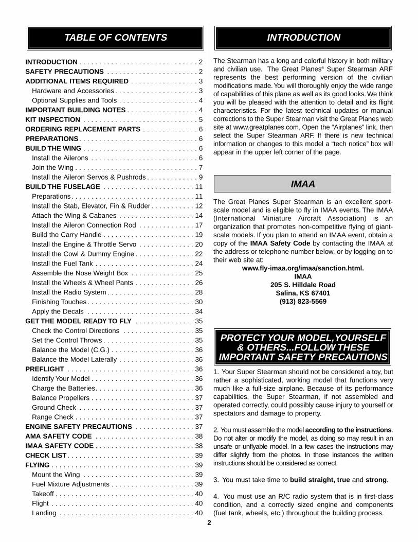
The Stearman has a long and colorful history in both militaryand civilian use. The Great Planes® Super Stearman ARFrepresents the best performing version of the civilianmodifications made.You will thoroughly enjoy the wide rangeof capabilities of this plane as well as its good looks. We thinkyou will be pleased with the attention to detail and its flightcharacteristics. For the latest technical updates or manualcorrections to the Super Stearman visit the Great Planes website at www.greatplanes.com. Open the “Airplanes” link, thenselect the Super Stearman ARF. If there is new technicalinformation or changes to this model a “tech notice” box willappear in the upper left corner of the page.
The Great Planes Super Stearman is an excellent sport-scale model and is eligible to fly in IMAA events. The IMAA(International Miniature Aircraft Association) is anorganization that promotes non-competitive flying of giant-scale models. If you plan to attend an IMAA event, obtain acopy of the IMAA Safety Code by contacting the IMAA atthe address or telephone number below, or by logging on totheir web site at:
www.fly-imaa.org/imaa/sanction.html.IMAA
205 S. Hilldale RoadSalina, KS 67401(913) 823-5569
1. Your Super Stearman should not be considered a toy, butrather a sophisticated, working model that functions verymuch like a full-size airplane. Because of its performancecapabilities, the Super Stearman, if not assembled andoperated correctly, could possibly cause injury to yourself orspectators and damage to property.
2. You must assemble the model according to the instructions.Do not alter or modify the model, as doing so may result in anunsafe or unflyable model. In a few cases the instructions maydiffer slightly from the photos. In those instances the writteninstructions should be considered as correct.
3. You must take time to build straight, true and strong.
4. You must use an R/C radio system that is in first-classcondition, and a correctly sized engine and components(fuel tank, wheels, etc.) throughout the building process.
PROTECT YOUR MODEL,YOURSELF& OTHERS...FOLLOW THESE
IMPORTANT SAFETY PRECAUTIONS
IMAA
INTRODUCTIONTABLE OF CONTENTS
2
5. You must correctly install all R/C and other componentsso that the model operates correctly on the ground and inthe air.
6. You must check the operation of the model before everyflight to insure that all equipment is operating and that themodel has remained structurally sound. Be sure to checkclevises or other connectors often and replace them if theyshow any signs of wear or fatigue.
7. If you are not already an experienced R/C pilot, youshould fly the model only with the help of a competent,experienced R/C pilot.
8. While this kit has been flight tested to exceed normal use,if the plane will be used for extremely high stress flying,such as racing, the modeler is responsible for taking stepsto reinforce the high stress points.
9. WARNING: The cowl, wheel pants and wing strutsincluded in this kit are made of fiberglass, the fibers of whichmay cause eye, skin and respiratory tract irritation. Neverblow into a part (wheel pant, cowl) to remove fiberglassdust, as the dust will blow back into your eyes. Always wearsafety goggles, a particle mask and rubber gloves whengrinding, drilling and sanding fiberglass parts. Vacuum theparts and the work area thoroughly after working withfiberglass parts.
Remember:Take your time and follow the instructions toend up with a well-built model that is straight and true.
If you have not flown this type of model before, werecommend that you get the assistance of an experiencedpilot in your R/C club for your first flights. If you’re not amember of a club, your local hobby shop has informationabout clubs in your area whose membership includesexperienced pilots.
In addition to joining an R/C club, we strongly recommend youjoin the AMA (Academy of Model Aeronautics). AMAmembership is required to fly at AMA sanctioned clubs. Thereare over 2,500 AMA chartered clubs across the country.Among other benefits, the AMA provides insurance to itsmembers who fly at sanctioned sites and events. Additionally,training programs and instructors are available at AMA clubsites to help you get started the right way. Contact the AMA atthe address or toll-free phone number below:
Academy of Model Aeronautics5151 East Memorial Drive
Muncie, IN 47302-9252Tele. (800) 435-9262Fax (765) 741-0057
Or via the Internet at: http://www.modelaircraft.org
This is the list of hardware and accessories required to finish theSuper Stearman. Order numbers are provided in parentheses.
Engine (refer to the engine size requirements on thecover of the manual)
4-Channel radio(1) standard servo (throttle)(4) servos with minimum of 54 oz/in torque (2-ailerons,
1-elevator, 1-rudder)(2) 12" [300mm] servo extensions (for aileron servos,
HCAM2711 for Futaba®)(1) Y-harness (for aileron servos, HCAM2751 for Futaba)(1) minimum 1,000mAh receiver battery
Propeller and spare propellers (refer to your enginemanufacturer's recommendations)
2' [600mm] large, silicone fuel tubing (GPMQ4133)
Optional: If building the Super Stearman with four aileronservos, in addition to the items previously mentioned youwill also need two more aileron servos, two more servoextensions and one more Y-harness.
In addition to common household tools and hobby tools, thisis the “short list” of the most important items required tobuild the Super Stearman. Great Planes Pro™ CA andEpoxy glue are recommended.
❏ R/C foam rubber (1/4" [6mm] - HCAQ1000, or 1/2"[13mm] - HCAQ1050)
❏ 1 oz. [30g] Thin Pro CA (GPMR6002)❏ 1 oz. [30g] Medium Pro CA+ (GPMR6008)❏ Pro 30-minute epoxy (GPMR6047)❏ Pro 6-minute epoxy (GPMR6045)❏ Drill bits: 1/16" [1.6mm], 5/64" [2mm], 3/32" [2.4mm],
1/8" [3.2mm], #29 or 9/64" [3.6mm], 3/16" [4.8mm], ❏ 3 pkgs Stick-on segmented lead weights (GPMQ4485)❏ #1 Hobby knife (HCAR0105)❏ #11 blades (5-pack, HCAR0211)❏ Small T-pins (100, HCAR5100)❏ R/C-56 canopy glue (JOZR5007)❏ CA applicator tips (HCAR3780)❏ Denatured Alcohol (for epoxy cleanup)❏ Flat Black Fuelproof Paint (for cockpit)❏ 8-32 Tap (GPMR8103)❏ 8-32 Tap Handle (GPMR8120)
Adhesives and Building Supplies
Hardware and Accessories
ADDITIONAL ITEMS REQUIRED
NOTE:We, as the kit manufacturer, provide you with a top quality
kit and great instructions, but ultimately the quality of your
finished model depends on how you build it; therefore, we cannot
in any way guarantee the performance of your completed model,
and no representations are expressed or implied as to the
performance or safety of your completed model.
3
4
Here is a list of optional tools mentioned in the manual thatwill help you build the Super Stearman
❏ 2 oz. [57g] spray CA activator (GPMR6035)- or -
❏ 4 oz. [113g] aerosol CA activator (GPMR634)❏ Epoxy brushes (6, GPMR8060)❏ Mixing sticks (50, GPMR8055)❏ Mixing cups (GPMR8056)❏ Builder’s Triangle Set (HCAR0480)❏ Curved-tip canopy scissors for trimming
plastic parts (HCAR0667)❏ Pliers with wire cutter (HCAR0630)❏ Robart Super Stand II (ROBP1402)❏ Hobbico® Duster™ can of compressed air (HCAR5500)❏ Masking tape (TOPR8018)❏ Microballoons (TOPR1090)❏ Threadlocker thread locking cement (GPMR6060)❏ Denatured alcohol (for epoxy clean up)❏ Rotary tool such as Dremel™
❏ Rotary tool reinforced cut-off wheel (GPMR8200)❏ Servo horn drill (HCAR0698)❏ Dead Center™ Engine Mount Hole Locator (GPMR8130)❏ AccuThrow™ Deflection Gauge (GPMR2405) ❏ CG Machine™ (GPMR2400)❏ Precision Magnetic Prop Balancer™ (TOPQ5700)❏ Fuel filler valve for glow fuel (GPMQ4160)
There are two types of screws used in this kit:
Sheet metal screws are designated by a number and a length.
For example #6 x 3/4" [19mm]
This is a number six screw that is 3/4" [19mm] long.
Machine screws are designated by a number, threads perinch, and a length.
For example 4-40 x 3/4" [19mm]
This is a number four screw that is 3/4" [19mm] long withforty threads per inch.
·When you see the term test fit in the instructions, itmeans that you should first position the part on theassembly without using any glue, then slightly modifyor custom fit the part as necessary for the best fit.
·Whenever the term glue is written you should rely uponyour experience to decide what type of glue to use. Whena specific type of adhesive works best for that step, theinstructions will make a recommendation.
·Whenever just epoxy is specified you may use either 30-minute (or 45-minute) epoxy or 6-minute epoxy. When30-minute epoxy is specified it is highly recommendedthat you use only 30-minute (or 45-minute) epoxy,because you will need the working time and/or theadditional strength.
·Photos and sketches are placed before the step theyrefer to. Frequently you can study photos in followingsteps to get another view of the same parts.
· The Super Stearman is factory-covered with Top FliteMonoKote film. Should repairs ever be required,MonoKote can be patched with additional MonoKotepurchased separately. MonoKote is packaged in six-footrolls, but some hobby shops also sell it by the foot. If onlya small piece of MonoKote is needed for a minor patch,perhaps a fellow modeler would give you some.MonoKote is applied with a model airplane covering iron,but in an emergency a regular iron could be used. A rollof MonoKote includes full instructions for application.Following are the colors used on this model and ordernumbers for six foot rolls.
White TOPQ0204Black TOPQ0208True Red TOPQ0227
·The stabilizer and wing incidences and engine thrustangles have been factory-built into this model. However,some technically minded modelers may wish to checkthese measurements anyway. To view this informationvisit the web site at www.greatplanes.com and click on“Technical Data.” Due to manufacturing tolerances whichwill have little or no effect on the way your model will fly,please expect slight deviations between your model andthe published values.
1/64" = .4mm1/32" = .8mm1/16" = 1.6mm3/32" = 2.4mm1/8" = 3.2mm
5/32" = 4mm3/16" = 4.8mm1/4" = 6.4mm3/8" = 9.5mm1/2" = 12.7mm5/8" = 15.9mm3/4" = 19mm
1" = 25.4mm2" = 50.8mm3" = 76.2mm6" = 152.4mm
12" = 304.8mm15" = 381mm18" = 457.2mm21" = 533.4mm24" = 609.6mm30" = 762mm36" = 914.4mm
1" = 25.4mm (conversion factor)
Metric Conversions
Important Building Notes
Optional Supplies and Tools

5
PARTS PHOTOGRAPHED
1. Fuselage2. Cowl3. Fin & Rudder4. Stab & Elevator5. Top, Left Wing & Aileron6. Top, Right Wing & Aileron7. Bottom, Left Wing & Aileron8. Bottom, Right Wing & Aileron9. Fuel Tank
10. Engine Mount11. Spinner12. Wheel Pants13. Landing Gear14. Cowl Ring15. Wheels16. Turtle Deck17. Windshields18. Cockpit Coaming19. Tail Wheel Assembly20. Cabanes21. Struts
Qty4-40 Threaded Metal Clevis . . . . . 43/16 x 2”Axle . . . . . . . . . . . . . . . . .2BrassEZConnector . . . . . . . . . . . .14-40 Blind Nuts . . . . . . . . . . . . . .204-40 Nuts . . . . . . . . . . . . . . . . . . .48-32 Blind Nuts . . . . . . . . . . . . . . .95/16-24 Axle Nut . . . . . . . . . . . . . .21/4-20 Blind Nut . . . . . . . . . . . . . .24-40 Nylon Lock Nuts . . . . . . . . . .8Large Nylon Control Horn . . . . . . .7Small Nylon Control Horn . . . . . . .41/4-20 Nylon Bolt . . . . . . . . . . . . . .2Nylon Clevis . . . . . . . . . . . . . . . . .7Nylon Retainer . . . . . . . . . . . . . . .12” x 9” Hinge material . . . . . . . . . .1Faslink . . . . . . . . . . . . . . . . . . . . .7Clevis Retainer . . . . . . . . . . . . . .11#4 x 1/2” SMS . . . . . . . . . . . . . . . .46-32 x1/4” SHCS . . . . . . . . . . . . . .64-40 x 1/8” Set Screw . . . . . . . . . .14-40x 1/4”SHCS . . . . . . . . . . . . . .1#2 x 3/8” SMS . . . . . . . . . . . . . . .28
Qty8-32 x 3/4” SHCS . . . . . . . . . . . . .54-40 x 1/2” SHCS . . . . . . . . . . . .164-40 x 1/2” Phillips Head M/S . . . .8#2 x 3/8” WoodScrew . . . . . . . . . . .88-32 x 1-1/4” SHCS . . . . . . . . . . . .48-32 x 1”SHCS . . . . . . . . . . . . . . .4#2 x 1/2” SMS . . . . . . . . . . . . . . . .4#4 x 1” MS . . . . . . . . . . . . . . . . . .43/32” Wheel Collar . . . . . . . . . . . . .15/32” Wheel Collar . . . . . . . . . . . . .23/16” Wheel Collar . . . . . . . . . . . . .41-1/4” Tail Wheel . . . . . . . . . . . . . .1.074 x 17-1/2”” Pushrod Wire . . . . .1.074 x 36” Pushrod Wire . . . . . . . .3.074 x 6” Pushrod Wire . . . . . . . . .4#4 Lock Washers . . . . . . . . . . . . .16#4 Flat Washer . . . . . . . . . . . . . .24#2 FlatWasher . . . . . . . . . . . . . . .10#8 Lock Washers . . . . . . . . . . . . . .8#8 FlatWasher . . . . . . . . . . . . . . . .84-40 x 3/4” SHCS . . . . . . . . . . . . .4
Parts Layout
Before starting to build, take an inventory of this kit to makesure it is complete, and inspect the parts to make sure theyare of acceptable quality. If any parts are missing or are notof acceptable quality, or if you need assistance withassembly, contact Product Support. When reportingdefective or missing parts, use the part names exactly asthey are written in the Kit Contents list on this page.
Great Planes Product Support3002 N Apollo Drive, Suite 1
Champaign, IL 61822
Telephone: (217) 398-8970, ext. 5Fax: (217) 398-7721
E-mail: [email protected]
1315 19
179
10
6
20
21
4
5
11
12
1318
2
87
14 16
PARTS NOT PHOTOGRAPHED
KIT INSPECTION

Replacement parts for the Great Planes Super Stearman ARFare available using the order numbers in the ReplacementParts List that follows. The fastest, most economical servicecan be provided by your hobby dealer or mail-order company.Parts may also be ordered directly from Hobby Services, butfull retail prices and shipping and handling charges will apply.Illinois and Nevada residents will also be charged sales tax.
To locate a hobby dealer, visit the Hobbico web site atwww.hobbico.com. Choose "Where to Buy" at the bottom of themenu on the left side of the page. Follow the instructionsprovided on the page to locate a U.S., Canadian or Internationaldealer. If a hobby shop is not available, replacement parts mayalso be ordered from Tower Hobbies at www.towerhobbies.com,or by calling toll free (800) 637-6050, or from Hobby Services bycalling (217) 398-0007, or via facsimile at (217) 398-7721. Ifordering via fax, include a Visa or MasterCard number andexpiration date for payment.
Mail parts orders and payments by personal check to:
Hobby Services3002 N Apollo Drive, Suite 1
Champaign IL 61822
Be certain to specify the order number exactly as listed in theReplacement Parts List. Payment by credit card or personalcheck only; no C.O.D.
If additional assistance is required for any reason, contactthe appropriate Product Support by e-mail or by telephoneat (217) 398-8970.
REPLACEMENT PARTS LIST
Order Number Description How to purchaseGPMA2460 . . . . . Bottom Wing Set . . . . . Hobby SupplierGPMA2461 . . . . . Top Wing Set . . . . . . . Hobby SupplierGPMA2462 . . . . . Fuselage Kit . . . . . . . . Hobby SupplierGPMA2463 . . . . . Tail Surface Set. . . . . . Hobby SupplierGPMA2464 . . . . . Landing Gear . . . . . . . Hobby SupplierGPMA2465 . . . . . Cowl Set . . . . . . . . . . . Hobby SupplierGPMA2466 . . . . . Wheel Pant Set . . . . . . Hobby SupplierGPMA2467 . . . . . Cabane Set. . . . . . . . . Hobby SupplierGPMA2468 . . . . . Strut Set . . . . . . . . . . . Hobby SupplierGPMA2469 . . . . . Spinner . . . . . . . . . . . . Hobby SupplierGPMA2470 . . . . . "Dummy" Radial Eng. . Hobby SupplierGPMA2471 . . . . . Decal Sheet . . . . . . . . Hobby SupplierGPMA2472 . . . . . Windscreen Set . . . . . Hobby SupplierGPMA2473 . . . . . Metal Brackets . . . . . . Hobby SupplierGPMZ0293 . . . . . Instruction Manual. . . . Hobby Supplier
Missing pieces. . . . . . Product SupportInstruction manual . . . Product SupportFull-size plans. . . . . . . . . Not available
If you have never worked with fiberglass there are a fewbasic things you should be aware of.
1. When you are cutting into fiberglass, be sure you arecutting the correct place. Unlike wood, you are not able to goback and easily fix a mistake.
2. Whenever you are gluing a part to the inside of fiberglass itis important to roughen the inside surface of the fiberglass with220-grit sandpaper, then wipe the area with alcohol. Themolding process leaves a waxy residue that can prevent agood bond between the glue and the parts being glued.
3. If you do not have a high-speed motor tool such as aDremel™ tool you should consider purchasing one orborrowing one from a fellow modeler. This combined with afiberglass cut-off wheel is going to be extremely helpful inthe assembly process.
WARNING: The cowl, wheel pants and fuselage included inthis kit are made of fiberglass, the fibers of which may causeeye, skin and respiratory tract irritation. Never blow into a partto remove fiberglass dust, as the dust will blow back into youreyes. Always wear safety goggles, a particle mask and rubbergloves when grinding, drilling and sanding fiberglass parts.Vacuum the parts and the work area thoroughly after workingwith fiberglass parts.
❏ 1. If you have not done so already, remove the majorparts of the kit from the box and inspect for damage. If anyparts are damaged or missing, contact Product Support atthe address or telephone number listed in the “KitInspection” section on page 5.
❏ 2. Carefully remove the tape and separate the aileronsfrom the wing and the elevators from the stab. If necessary,use a covering iron with a covering sock on high heat totighten the covering. Apply pressure over sheeted areas tothoroughly bond the covering to the wood.
PREPARATIONS
Important Information aboutWorking with Fiberglass
Ordering Replacement Parts
6

Do the right wing first so your work matches thephotos the first time through.You can do one wing at atime, or work on them together.
❏ ❏ 1. Drill a 3/32" [2.4mm] hole, 1/2" [13mm] deep in thecenter of each hinge slot to allow the CA to “wick” in. Follow-up with a #11 blade to clean out the slots.Hint: If you have one, use a high-speed rotary tool to drillthe holes.
❏ ❏ 2. Use a sharp #11 blade to cut a strip of covering fromthe hinge slots in the wing and aileron.
❏ ❏ 3. Cut fourteen 3/4" x 1" [19 x 25mm] hinges from the CA hinge strip. Snip offthe corners so they go in easier.
❏ ❏ 4. Test fit the ailerons to the wing with the hinges. Ifthe hinges don’t remain centered, stick a pin through themiddle of the hinge to hold it in position.
❏ ❏ 5. Remove any pins you may have inserted into thehinges. Adjust the aileron so there is a small gap between theLE of the aileron and the wing. The gap should be small, justenough to see light through or to slip a piece of paper through.
❏ ❏ 6. Apply six drops of thin CA to the top and bottom ofeach hinge. Do not use CA accelerator. After the CA hasfully cured, test the hinges by pulling on the aileron.
❏ 7. Repeat steps 1- 6 for the left wing panel.
❏ 8. Follow the same procedure for installing the aileronson the top wing panels. Install the ailerons to the top wingpanel with three hinges in each aileron.
Before installing the aileron servos you must make adecision on whether you will use two or four servos to drivethe four ailerons. A separate servo bay is located in eachwing panel for a four-servo installation. Should you chooseto use the two-servo installation an aileron connecting rodgoes between the top and bottom ailerons. The use of aconnecting rod between the top and bottom wing is “scale”for a Stearman. If you choose to use the four servos you willnot be able to use the aileron connecting rod due to thedifferential that is created between the top and bottomaileron. You will not have any noticeable performancedifference with either option. If you do use two servos youwill need to make sure they are at least 54 oz-in servos.Using four servos allows you to use less powerful servos(and most likely less expensive servos) but they will need tobe at least 30 oz-in servos.
The following steps are required whether you install two orfour servos.
❏ ❏ 1. Cut away the covering from the servo bay in the bottomof the right bottom wing panel. Turn the wing over and cut thecovering from the hole in the top of the wing at the wing root.
Join the Wing
Install the Ailerons
BUILD THE WING
7

❏ ❏ 2. A string is taped inside the servo bay. Carefullyremove the string from the servo bay and tape it to theoutside of the wing to prevent it from dropping back into thewing. The other end of the string is taped to the root rib.Remove the tape, thread the string through the small holesyou cut the covering from on the bottom of the wing andtape the string to the wing.
❏ 3. Repeat steps 1 and 2 for the left bottom wing.
If you are installing servos in the top wing, proceed withsteps 4 and 5. If not, skip ahead to step 6.
❏ ❏ 4. Starting with the right wing panel for the top wing,cut away the covering from the servo opening on the bottomof the wing and the covering from the hole at the root of thewing. Remove the tape from the root rib, thread the stringthrough the hole and tape the string to the wing. Tape thestring in the servo bay to the wing, too.
❏ 5. Repeat step 4 for the left wing.
❏ 6. Locate three 1/8" [3mm] straight plywood wing joinersand three 1/8" [3mm] plywood wing joiners that are angled.Using 6-minute epoxy, glue the straight ones together to formone 3/8" [10mm] joiner and glue the three angled onestogether forming the 3/8" [10mm] angled wing joiner.
❏ 7. After the glue has cured, test fit the angled joiner intothe bottom wing panels and the straight joiner into the topwing panels. Sand the joiners as needed to get a good fit.
❏ 8. When you are satisfied with the fit of the joiners, gluethe angled joiner into the bottom wing panels with 30-minute epoxy. Be sure that the top of the joiner istowards the top of the wing. When gluing the wing panelstogether be sure to get glue into the joiner pockets in thewing. This can be done by applying the glue into the pocketwith a small stick. Apply glue to the pocket, the joiner andthe root rib of the wing.
Before the glue cures, set one wing half flat on your bench.Insert the 1/2" x1/2" x 3" [13 x 13 x 75mm] balsa block underthe trailing edge of the wing that sits flat on the workbench.Block up the wing tip of the other wing half with the 2-1/16" x2-1/16" x 2-1/16" [52 x 52 x 52mm] balsa block included in thekit. Put small weights on the wing half that is flat on the benchto keep it lying flat and leave the block under the wing tip of theother wing half while the glue cures.
8

❏ 9. Hold the wing together with masking tape while theglue is curing. Excess epoxy can be cleaned away withdenatured alcohol and a paper towel.
❏ 10. Glue the top wing together using the straight wingjoiner and following the same gluing procedure used on thebottom wing. Note: There is no dihedral on the top wing.After gluing the wing together be sure it remains flat on theworkbench while the glue cures.
❏ ❏ 1. On the lower wing, install a 12" [305mm] servo extensiononto the servo lead. Secure the extension to the lead with tape, apiece of shrink tube or some other method to keep them fromcoming unplugged.
❏ ❏ 2. Tie the string to the servo extension. At the root ofthe wing the other end of the string is taped. Pull the stringand the servo lead through the wing. Untie the string fromthe lead and insert the lead through the small hole you cutthe covering from. Tape the lead to the wing to prevent itfrom falling back into the wing.
❏ ❏ 3. Install the servo into the servo opening. Drill throughthe servo mounting holes with a 1/16" [1.6mm] drill bit.Remove the servo from the servo opening. Install and thenremove a servo mounting screw into each of the holes youhave drilled. Apply a drop of thin CA into the holes to hardenthe threads. Once the glue has cured install the servo intothe servo opening using the hardware included with yourservo. Center the servo, then install a servo arm as shown.The arm should be pointing towards the wingtip.
❏ ❏ 4. Place a nylon clevis in line with the last hole in theservo arm. When positioned properly the control horn willrest on a hardwood plate in the aileron. Mark the location ofthe mounting holes onto the aileron. Drill a 1/16" [1.6mm]hole on the marks, drilling through the plywood plate but notthrough the top of the aileron. Insert and remove a #2 x3/8"[10mm] screw into each of the holes. Apply a couple dropsof thin CA into the holes to harden the threads. Once theglue has cured attach the horn to the aileron with two #2 x3/8" [10mm] screws.
❏ ❏ 5. Thread a nylon clevis onto a .074 x 6" [152mm]threaded wire 20 turns. Slide a silicone clevis retainer ontothe clevis. Install the clevis into the second hole from theend of the control horn, then slide the silicone retainer over
Install the Aileron Servos & Pushrods
9
the clevis. Drill a 5/64" [2mm] hole in the outer hole of theservo arm. Center the servo and the aileron. With a fine-tipmarker, mark the wire where it aligns with the outer hole ofthe servo arm. Make a 90 degree bend on the mark. Cut thewire so the wire is 3/8" [10mm] in length after the bend.Insert the wire into the servo arm and lock it in place with anylon Faslink.
❏ 6. Repeat steps 1-5 for the left wing panel.
If you are installing servos in the top wing, repeat steps 1-6 for the top wing. If not, skip ahead to Step 12. Steps 7- 11 are only if you are installing servos in the top wing.
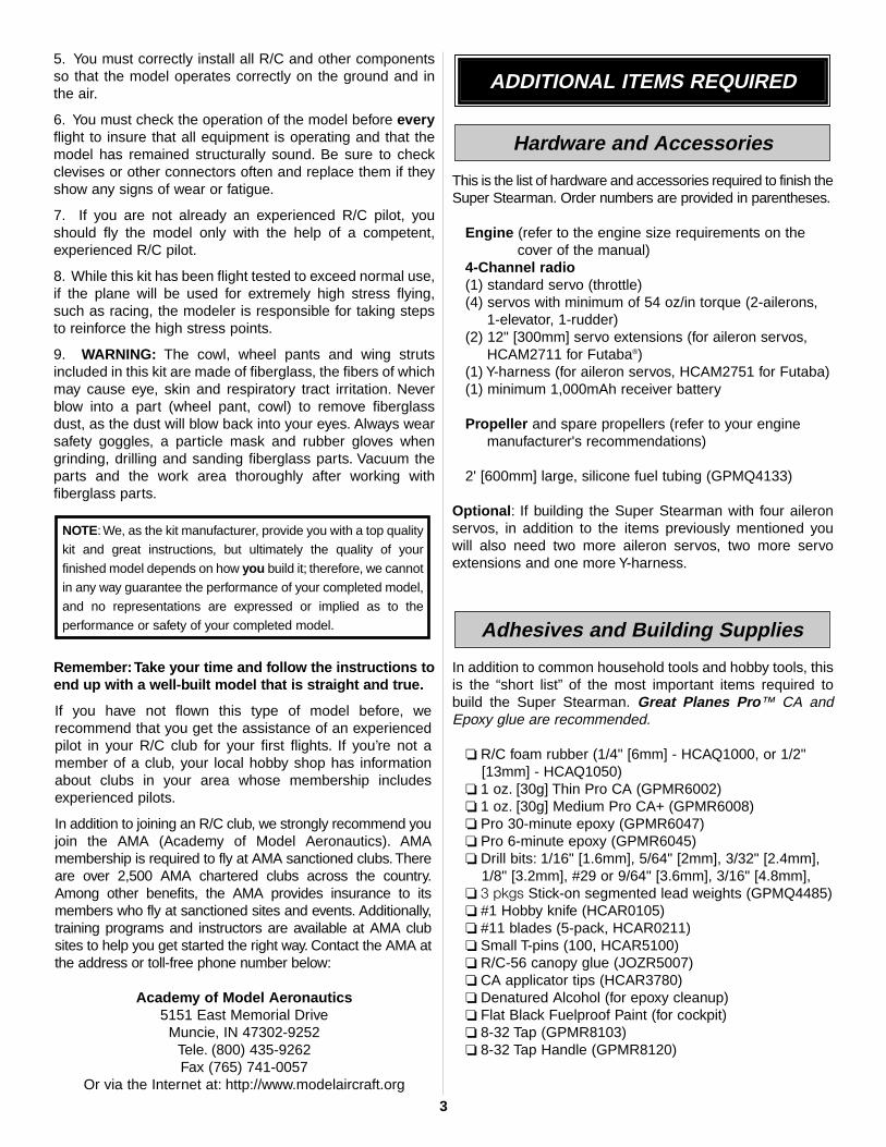
❏ 7. A “Y” harness is required to connect the servos in theupper wing to the receiver. Plug the two servo leads in thetop wing into a “Y” harness compatible with your radiosystem. To provide a plug into the receiver we have used aslightly modified Ernst Charge Receptacle (ERN3124 forFutaba) and a 12" [305mm] servo extension.
❏ 8. Cut the charge receptacle in half just above the locking fingers.
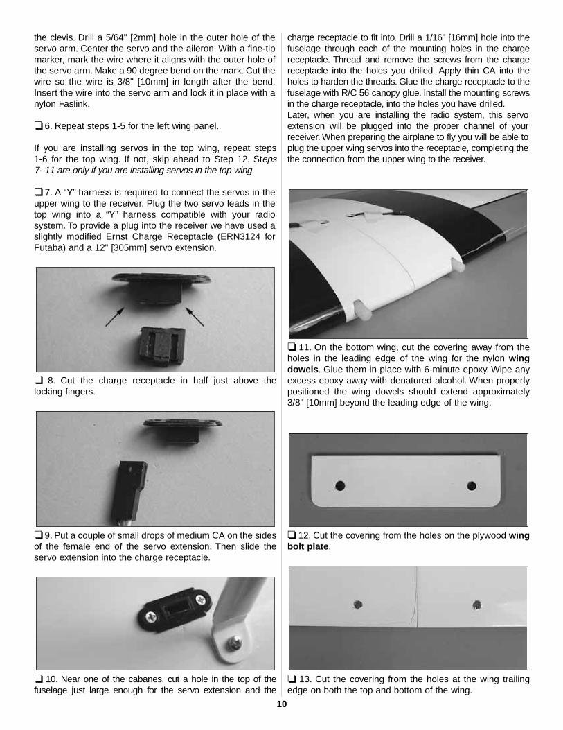
❏ 9. Put a couple of small drops of medium CA on the sidesof the female end of the servo extension. Then slide theservo extension into the charge receptacle.
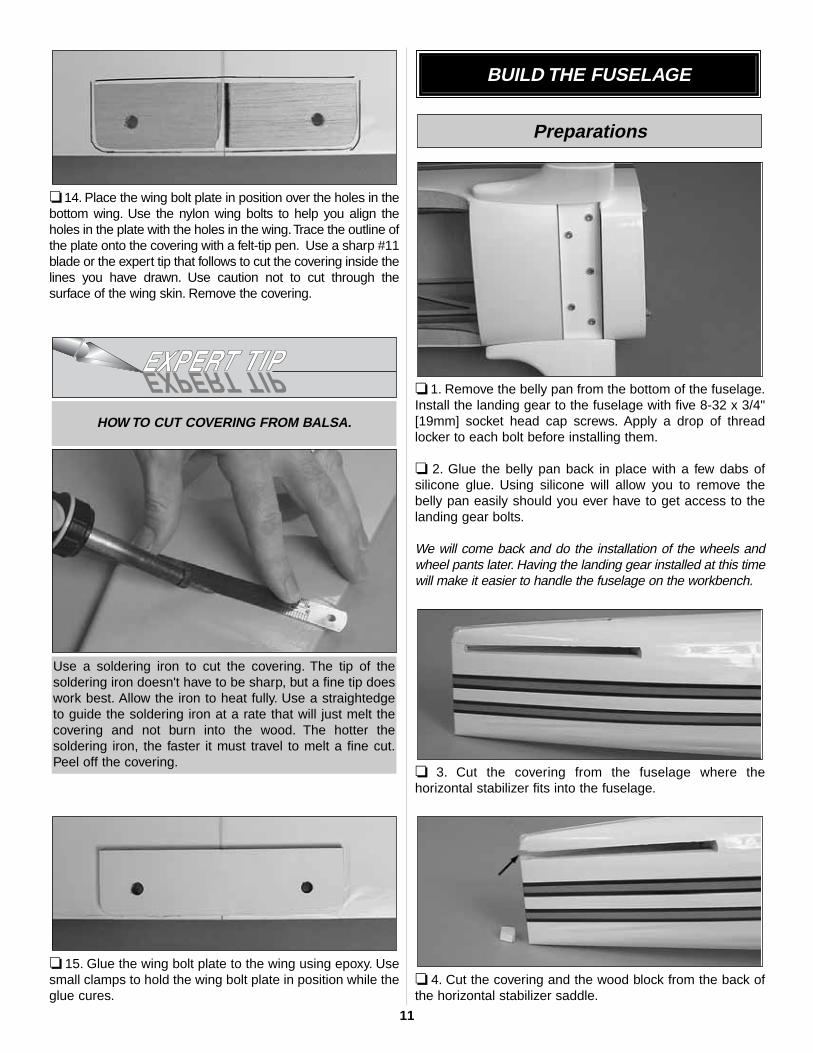
❏ 10. Near one of the cabanes, cut a hole in the top of thefuselage just large enough for the servo extension and the
charge receptacle to fit into. Drill a 1/16" [16mm] hole into thefuselage through each of the mounting holes in the chargereceptacle. Thread and remove the screws from the chargereceptacle into the holes you drilled. Apply thin CA into theholes to harden the threads. Glue the charge receptacle to thefuselage with R/C 56 canopy glue. Install the mounting screwsin the charge receptacle, into the holes you have drilled.Later, when you are installing the radio system, this servoextension will be plugged into the proper channel of yourreceiver. When preparing the airplane to fly you will be able toplug the upper wing servos into the receptacle, completing thethe connection from the upper wing to the receiver.
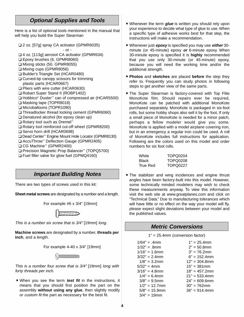
❏ 11. On the bottom wing, cut the covering away from theholes in the leading edge of the wing for the nylon wingdowels. Glue them in place with 6-minute epoxy. Wipe anyexcess epoxy away with denatured alcohol. When properlypositioned the wing dowels should extend approximately3/8" [10mm] beyond the leading edge of the wing.
❏ 12. Cut the covering from the holes on the plywood wingbolt plate.
❏ 13. Cut the covering from the holes at the wing trailingedge on both the top and bottom of the wing.
10
❏ 14. Place the wing bolt plate in position over the holes in thebottom wing. Use the nylon wing bolts to help you align theholes in the plate with the holes in the wing.Trace the outline ofthe plate onto the covering with a felt-tip pen. Use a sharp #11blade or the expert tip that follows to cut the covering inside thelines you have drawn. Use caution not to cut through thesurface of the wing skin. Remove the covering.
❏ 15. Glue the wing bolt plate to the wing using epoxy. Usesmall clamps to hold the wing bolt plate in position while theglue cures.
❏ 1. Remove the belly pan from the bottom of the fuselage.Install the landing gear to the fuselage with five 8-32 x 3/4"[19mm] socket head cap screws. Apply a drop of threadlocker to each bolt before installing them.
❏ 2. Glue the belly pan back in place with a few dabs ofsilicone glue. Using silicone will allow you to remove thebelly pan easily should you ever have to get access to thelanding gear bolts.
We will come back and do the installation of the wheels andwheel pants later. Having the landing gear installed at this timewill make it easier to handle the fuselage on the workbench.
❏ 3. Cut the covering from the fuselage where thehorizontal stabilizer fits into the fuselage.
❏ 4. Cut the covering and the wood block from the back ofthe horizontal stabilizer saddle.
Preparations
BUILD THE FUSELAGE
Use a soldering iron to cut the covering. The tip of thesoldering iron doesn't have to be sharp, but a fine tip doeswork best. Allow the iron to heat fully. Use a straightedgeto guide the soldering iron at a rate that will just melt thecovering and not burn into the wood. The hotter thesoldering iron, the faster it must travel to melt a fine cut.Peel off the covering.
HOW TO CUT COVERING FROM BALSA.
11

❏ 1.Temporarily attach the lower wing to the fuselage with the1/4-20 nylon bolts. Slide the horizontal stabilizer into the slotin the fuselage. Stand back and look at the stab in relation tothe wing.The stab should be parallel with the wing. If not, sandthe stab saddle until the stab and wing are aligned.
❏ 2. Measure the distance from the tip of the stab to the tip ofeach wing. Adjust the position of the stab until they are equal.
❏ 3. Using a felt-tip pen, mark the outline of the fuselage onthe top and the bottom of the stab.
❏ 4. Cut the covering on the top and bottom of the stabinside the line you have drawn. Use the same technique forremoving the covering from the wing.
❏ 5.Glue the stab in place with 30-minute epoxy.Excess epoxycan be cleaned away with a paper towel and denaturedalcohol. After the stab is positioned and all excess epoxy hasbeen cleaned away, temporarily install the vertical fin part ofthe way into the slot. Just put it into place enough to verify thatyou have not pushed the wood fuselage fairings too closetogether and that the slot in the stab is aligned with the openingfor the fin. Remove the fin and allow the glue to cure. If any gluehas gotten on the fin, remove it with denatured alcohol.
Install the Stab, Elevator, Fin & Rudder
12

❏ 6. Remove the bottom wing from the fuselage.Temporarily install the fin into the slot in the top of thefuselage. Using a fine-point felt-tip pen, mark the outline ofthe fuselage onto the fin. Cut the covering from the fin usingthe same method used earlier.
❏ 7. Test fit the fin into the fuselage. Check to be sure thefin is perpendicular to the stab. If it is not, sand the side ofthe fin to make minor adjustments. Once you are satisfiedwith the fit, glue the fin to the fuselage with epoxy.
❏ 8. Using the same installation method used previously,install three hinges into each elevator half. Then install theelevators into the stab. Glue the hinges using thin CA.
Did you know?...Built as a private venture by theStearman Aircraft Company of Wichita (bought by Boeing in1934), this two-seat biplane was of mixed construction. Thewings were of wood with fabric covering while the fuselagehad a tough, welded steel framework, also fabric covered. In1936, the Army tentatively bought 26 airframes from Boeing(the Model 75), which the Army named the PT-13. With waron the horizon, this trickle of acquisition soon turned into atorrent; 3519 were delivered in 1940 alone.
Did you know?...The Stearman gained a reputation asa rugged airplane and a good teacher. Officially named theBoeing Model 75, the plane was (and still is) persistentlyknown as the “Stearman” by many who flew them. It wascalled the “PT” by the Army, “N2S” by the Navy and “Kaydet”by Canadian forces. By whatever name, more than 10,000were built by the end of 1945 and at least 1,000 are stillflying today worldwide.
❏ 9. Locate the tail wheel wire. Test fit it into the two slots in theback of the fuselage. Use your hobby knife to clean out the slotsif it is too tight. Once satisfied with the fit, remove the wire fromthe slots. Apply a couple of drops of oil to the wire where itpasses through the nylon bearings. This will prevent glue fromgetting onto the wire. Apply epoxy to the nylon tabs and theninstall the tail wheel wire into the fuselage.
13

❏ 10. Cut the covering from the front of the balsa triangle tailblock.Cut the covering from the back of the fuselage where theblock will be glued to the fuselage. Test fit the block over thelanding gear wire. Make adjustments to the slot in the block asneeded. Glue the block to the fuselage. Be careful not to getglue on the wire.
❏ 11. Cut the covering from the hole on the leading edge,bottom of the rudder. Test fit the hinges into the rudder andthen fit the rudder to the fin and fuselage. Make anyadjustments that may be needed to the slot in the rudder.When you are satisfied everything fits well, put a smallamount of epoxy into the hole in the rudder, install thehinges in the rudder and install the rudder to the fin.
❏ 12. Glue the hinges to the fin and rudder with thin CA.
Did you know?...After World War II, many Stearmanswere fitted with Pratt & Whitney 450 h.p. engines and utilizedas crop dusters. These more powerful Stearmans are alsocommonly known as the “Super Stearman” and used forwing-walking or aerobatic routines at air shows.
❏ 1. Attach the lower wing to the fuselage with the 1/4-20nylon bolts.
❏ ❏ 2. Locate eight metal cabane mounting brackets. Thephotograph identifies the correct bracket for the top and bottomwing. Set the four brackets for the top wing to the side. We willbe installing the brackets on the bottom wing first.
Do the right wing first so your work matches the photosthe first time through.
Attach the Wing and Cabanes
14

❏ ❏ 3. Look closely on the top of the bottom wing and youwill find a small pin hole locating the blind nuts for thecabane mounting bolts. Cut the covering from each of theholes. Note: 4-40 blind nuts have been installed in the wingfor all of the cabane mounting bolts. All of the blind nuts areglued into the wing and have a small wood plate backingthem up. It is possible that a blind nut could have a bit of gluein the threads. In most cases the installation of the boltshould free the glue. If not, run a 4-40 tap through thethreads to clear the glue.
❏ ❏ 4. Mount the bottom wing cabane brackets in each ofthe holes in the right wing panel with a 4-40 x 1/2" [13mm]socket head cap screw and a #4 lock washer. Do not fullytighten the bracket to the wing yet.
❏ ❏ 5. Position the “N” strut to the bracket. Located on thestrut is a piece of masking tape with an arrow that indicatesthe top, front of the strut.
❏ ❏ 6. Attach the strut to the bracket as shown with a 4-40x 1/2" [13mm] phillips head screw, a #4 washer and a 4-40nylon lock nut.
❏ 7. If you have not been doing the bracket installation onboth the right and left wing, go back and repeat steps 3-6 forthe left wing panel.
15

❏ 8. Locate the pin holes and cut the covering from the blindnuts in the bottom of the top wing.Four are located in the centerof the wing and two are located at each end of the wing.
❏ 9. Install the center cabanes with 4-40 x 1/2" [13mm]socket head cap screws and #4 lock washers. Be sure youmount the cabanes as shown.
❏ 10. Install the four remaining brackets in the blind nuts atthe ends of the wing.
❏ 11. Place the top wing onto the “N” struts. Attach the topwing to the “N” struts with 4-40 x 1/2" [13mm] phillips headscrews, #4 washers and 4-40 nylon lock nuts the same wayyou installed the strut to the lower brackets.
❏ 12. Set the fuselage on the firewall. Look at the relation ofthe top wing to the bottom wing. Be sure the top wing isparallel with bottom wing. Adjust the top wing as needed.Then carefully set the fuselage back on the landing gear.
❏ 13. Without disturbing the top wing, push a T-pin into thefuselage through each of the cabane mounting holes. Push thepin hard to verify that the mounting holes are positioned overthe hardwood rails. If you do not find hardwood and only hitbalsa wood, check to see if you have mounted the centercabanes properly. If you have the center cabanes backwardsthey will not align over the hardwood rails.
❏ 14. Drill a 5/64" [2mm] hole through each of the fourmounting holes in the center cabanes. When you drill theseholes you must be drilling into the hardwood rails located inthe fuselage.
❏ 15. Install and then remove a #4 x 1/2" sheet metal screwinto each of the four holes. Apply a couple drops of thin CAinto each of the holes to harden the threads. After the gluehas cured permanently install the screws into the fuselage.
16
If you have decided to install four servos in the wingsinstead of two, skip the 12 steps in this section and proceedto, “Build the Carry Handle”.
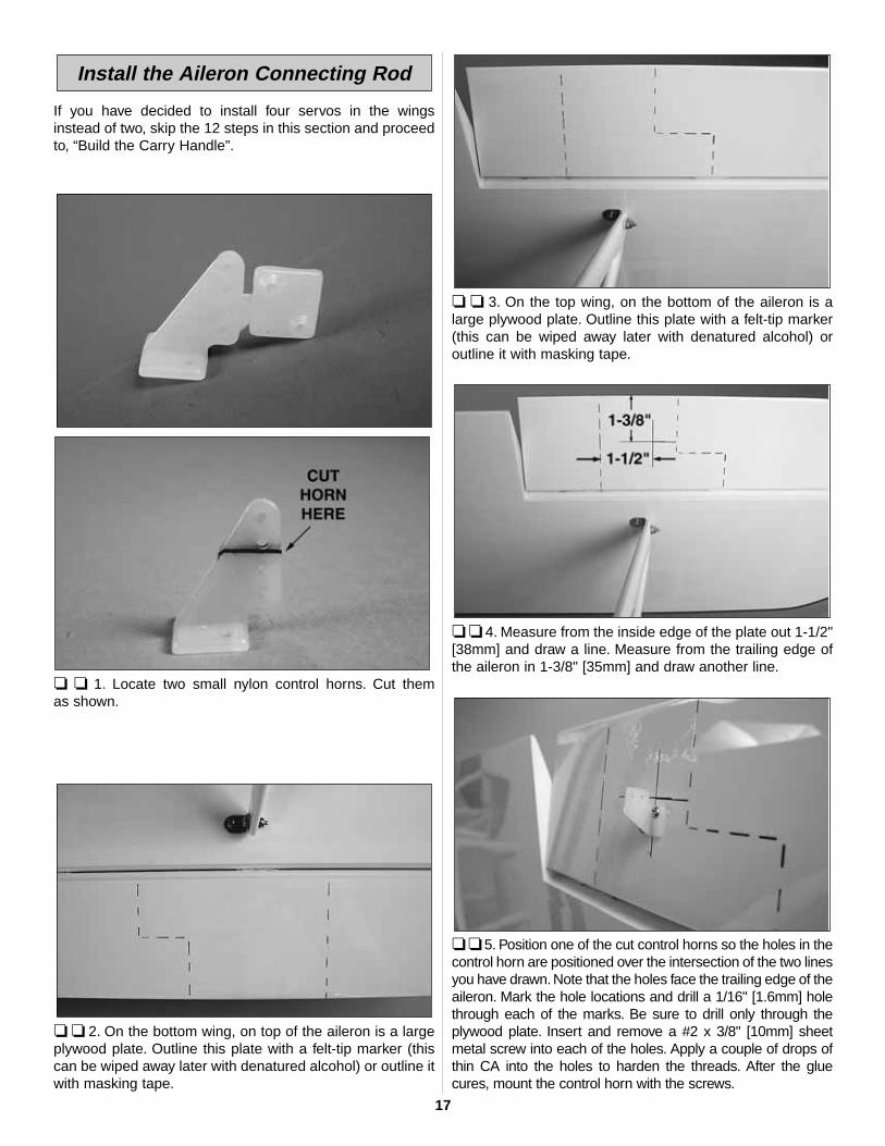
❏ ❏ 1. Locate two small nylon control horns. Cut them as shown.
❏ ❏ 2. On the bottom wing, on top of the aileron is a largeplywood plate. Outline this plate with a felt-tip marker (thiscan be wiped away later with denatured alcohol) or outline itwith masking tape.
❏ ❏ 3. On the top wing, on the bottom of the aileron is alarge plywood plate. Outline this plate with a felt-tip marker(this can be wiped away later with denatured alcohol) oroutline it with masking tape.
❏ ❏ 4. Measure from the inside edge of the plate out 1-1/2"[38mm] and draw a line. Measure from the trailing edge ofthe aileron in 1-3/8" [35mm] and draw another line.
❏ ❏ 5. Position one of the cut control horns so the holes in thecontrol horn are positioned over the intersection of the two linesyou have drawn. Note that the holes face the trailing edge of theaileron. Mark the hole locations and drill a 1/16" [1.6mm] holethrough each of the marks. Be sure to drill only through theplywood plate. Insert and remove a #2 x 3/8" [10mm] sheetmetal screw into each of the holes. Apply a couple of drops ofthin CA into the holes to harden the threads. After the gluecures, mount the control horn with the screws.
Install the Aileron Connecting Rod
17
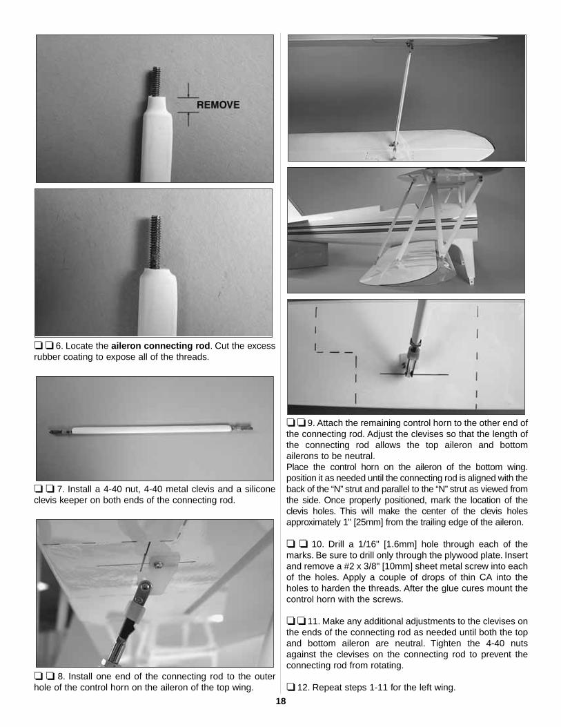
❏ ❏ 6. Locate the aileron connecting rod. Cut the excessrubber coating to expose all of the threads.
❏ ❏ 7. Install a 4-40 nut, 4-40 metal clevis and a siliconeclevis keeper on both ends of the connecting rod.
❏ ❏ 8. Install one end of the connecting rod to the outerhole of the control horn on the aileron of the top wing.
❏ ❏ 9. Attach the remaining control horn to the other end ofthe connecting rod. Adjust the clevises so that the length ofthe connecting rod allows the top aileron and bottomailerons to be neutral.Place the control horn on the aileron of the bottom wing.position it as needed until the connecting rod is aligned with theback of the “N” strut and parallel to the “N” strut as viewed fromthe side. Once properly positioned, mark the location of theclevis holes. This will make the center of the clevis holesapproximately 1" [25mm] from the trailing edge of the aileron.
❏ ❏ 10. Drill a 1/16" [1.6mm] hole through each of themarks. Be sure to drill only through the plywood plate. Insertand remove a #2 x 3/8" [10mm] sheet metal screw into eachof the holes. Apply a couple of drops of thin CA into theholes to harden the threads. After the glue cures mount thecontrol horn with the screws.
❏ ❏ 11. Make any additional adjustments to the clevises onthe ends of the connecting rod as needed until both the topand bottom aileron are neutral. Tighten the 4-40 nutsagainst the clevises on the connecting rod to prevent theconnecting rod from rotating.
❏ 12. Repeat steps 1-11 for the left wing.
18
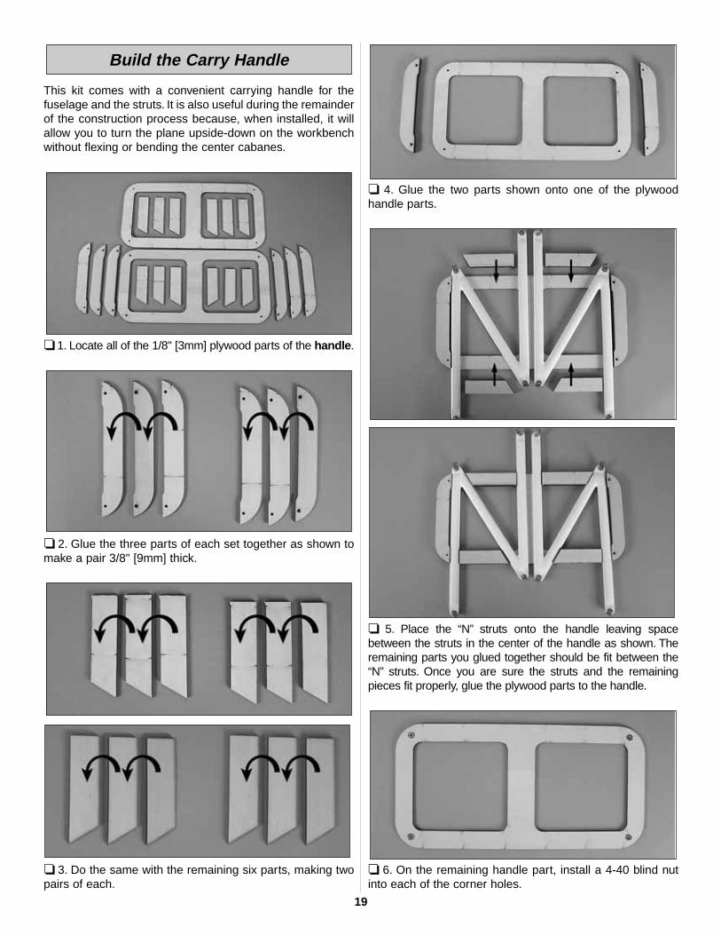
This kit comes with a convenient carrying handle for thefuselage and the struts. It is also useful during the remainderof the construction process because, when installed, it willallow you to turn the plane upside-down on the workbenchwithout flexing or bending the center cabanes.
❏ 1. Locate all of the 1/8" [3mm] plywood parts of the handle.
❏ 2. Glue the three parts of each set together as shown tomake a pair 3/8" [9mm] thick.
❏ 3. Do the same with the remaining six parts, making twopairs of each.
❏ 4. Glue the two parts shown onto one of the plywoodhandle parts.
❏ 5. Place the “N” struts onto the handle leaving spacebetween the struts in the center of the handle as shown. Theremaining parts you glued together should be fit between the“N” struts. Once you are sure the struts and the remainingpieces fit properly, glue the plywood parts to the handle.
❏ 6. On the remaining handle part, install a 4-40 blind nutinto each of the corner holes.
Build the Carry Handle
19
❏ 7. Place the two “N” struts into the handle and the twoaileron connecting rods between the struts. Put the handletop onto the part of the handle holding the struts and placethe completed handle on top of the cabanes. Secure thehandle to the cabanes with four 4-40 x 3/4" [19mm] sockethead cap screws and #4 flat washers. This is how thecompleted handle looks when you are storing the parts ortaking the plane to the field.
❏ 8. For the following building steps it will be better toremove everything from the handle. Do this now and securethe empty handle to the cabanes.
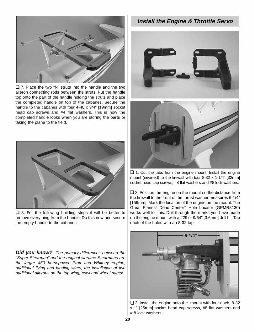
Did you know?...The primary differences between the“Super Stearman” and the original wartime Stearmans arethe larger 450 horsepower Pratt and Whitney engine,additional flying and landing wires, the installation of twoadditional ailerons on the top wing, cowl and wheel pants!
❏ 1. Cut the tabs from the engine mount. Install the enginemount (inverted) to the firewall with four 8-32 x 1-1/4" [32mm]socket head cap screws, #8 flat washers and #8 lock washers.
❏ 2. Position the engine on the mount so the distance fromthe firewall to the front of the thrust washer measures 6-1/4"[159mm]. Mark the location of the engine on the mount. TheGreat Planes® Dead Center™ Hole Locator (GPMR8130)works well for this. Drill through the marks you have madeon the engine mount with a #29 or 9/64" [3.6mm] drill bit.Tapeach of the holes with an 8-32 tap.
❏ 3. Install the engine onto the mount with four each, 8-32x 1" [25mm] socket head cap screws, #8 flat washers and # 8 lock washers.
Install the Engine & Throttle Servo
20
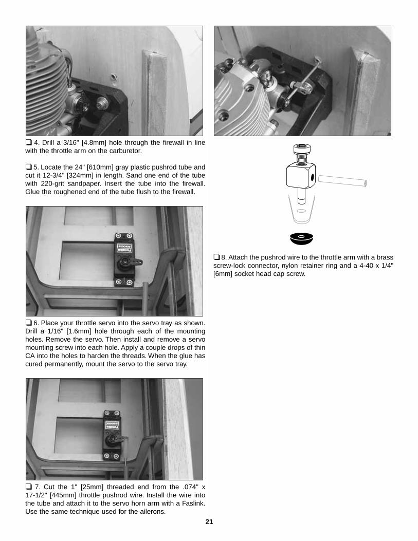
❏ 4. Drill a 3/16" [4.8mm] hole through the firewall in linewith the throttle arm on the carburetor.
❏ 5. Locate the 24" [610mm] gray plastic pushrod tube andcut it 12-3/4" [324mm] in length. Sand one end of the tubewith 220-grit sandpaper. Insert the tube into the firewall.Glue the roughened end of the tube flush to the firewall.
❏ 6. Place your throttle servo into the servo tray as shown.Drill a 1/16" [1.6mm] hole through each of the mountingholes. Remove the servo. Then install and remove a servomounting screw into each hole. Apply a couple drops of thinCA into the holes to harden the threads. When the glue hascured permanently, mount the servo to the servo tray.
❏ 7. Cut the 1" [25mm] threaded end from the .074" x 17-1/2" [445mm] throttle pushrod wire. Install the wire intothe tube and attach it to the servo horn arm with a Faslink.Use the same technique used for the ailerons.
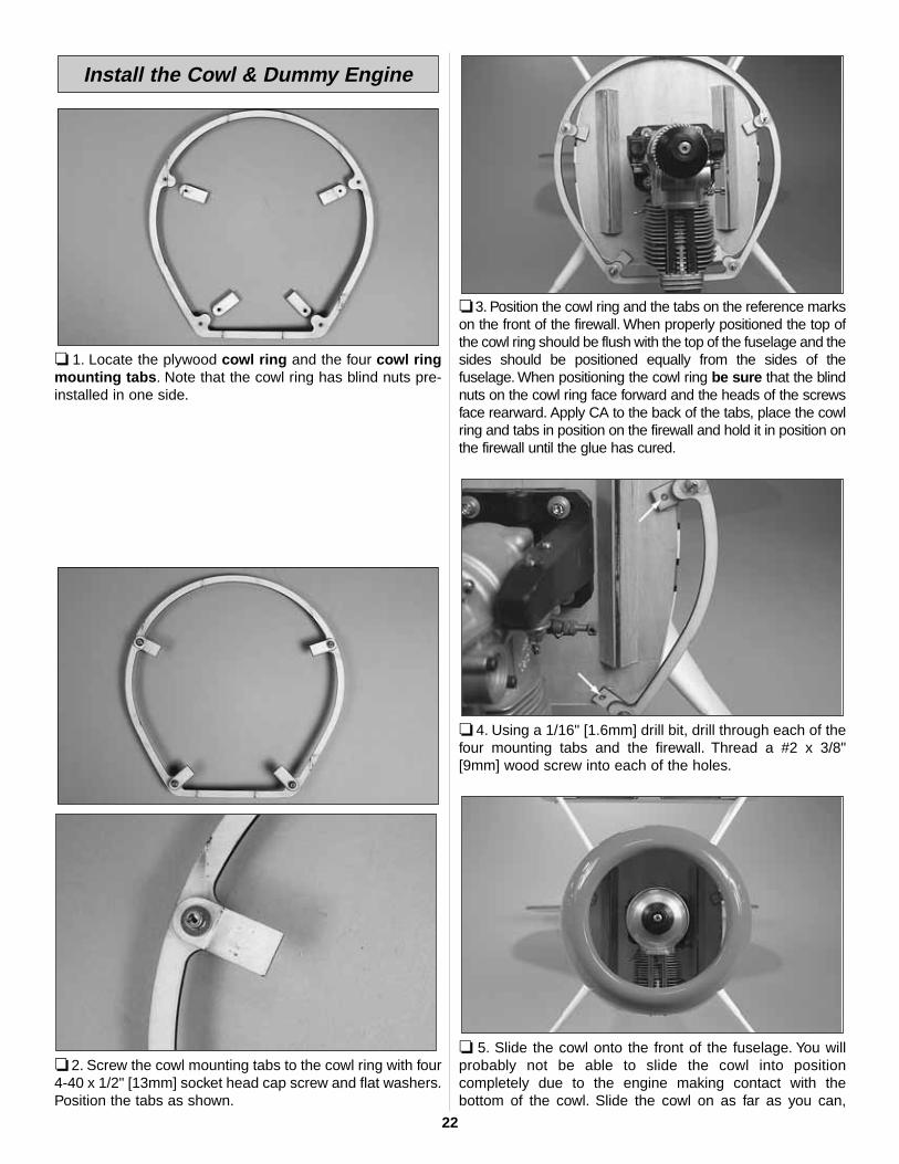
❏ 8. Attach the pushrod wire to the throttle arm with a brassscrew-lock connector, nylon retainer ring and a 4-40 x 1/4"[6mm] socket head cap screw.
21
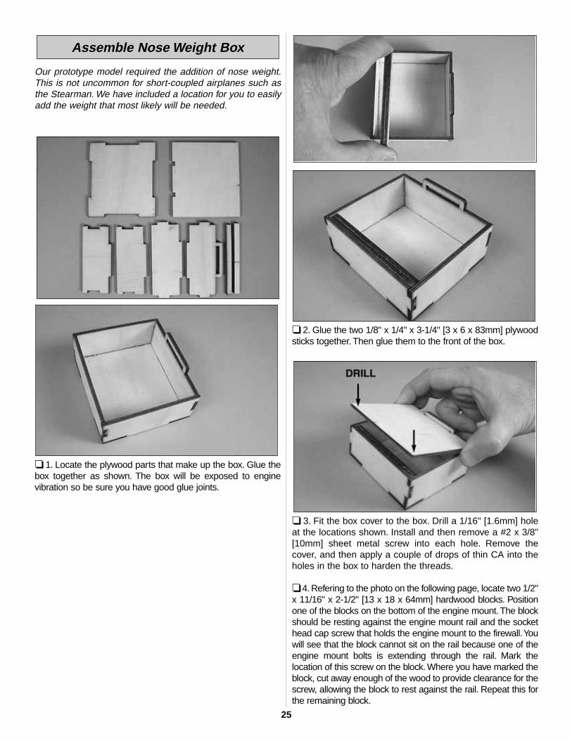
❏ 1. Locate the plywood cowl ring and the four cowl ringmounting tabs. Note that the cowl ring has blind nuts pre-installed in one side.
❏ 2. Screw the cowl mounting tabs to the cowl ring with four4-40 x 1/2" [13mm] socket head cap screw and flat washers.Position the tabs as shown.
❏ 3. Position the cowl ring and the tabs on the reference markson the front of the firewall. When properly positioned the top ofthe cowl ring should be flush with the top of the fuselage and thesides should be positioned equally from the sides of thefuselage. When positioning the cowl ring be sure that the blindnuts on the cowl ring face forward and the heads of the screwsface rearward. Apply CA to the back of the tabs, place the cowlring and tabs in position on the firewall and hold it in position onthe firewall until the glue has cured.
❏ 4. Using a 1/16" [1.6mm] drill bit, drill through each of thefour mounting tabs and the firewall. Thread a #2 x 3/8"[9mm] wood screw into each of the holes.
❏ 5. Slide the cowl onto the front of the fuselage. You willprobably not be able to slide the cowl into positioncompletely due to the engine making contact with thebottom of the cowl. Slide the cowl on as far as you can,
Install the Cowl & Dummy Engine
22

centering it as much as possible. At the point where theengine begins to make contact with the cowl, mark theinside of the cowl with a felt-tip marker. Make small cut outsin the cowl where the engine contacts the fuselage until youcan completely slide the cowl into position. Install the backplate of the spinner and the propeller onto the enginecrankshaft. This will help you position the cowl. Whencentering the cowl, be sure to match the stripes on the sideof the cowl with the stripes on the side of the fuselage.
❏ 6. Once you are satisfied with the position of the cowl,tack glue the cowl ring to the cowl with medium CA using aCA applicator tip. Apply the glue on the back of the cowl ringand apply some CA accelerator to the glue to enable it tocure quickly. Do this on both sides of the cowl.
❏ 7. Remove the four screws from the cowl ring, and thenremove the cowl from the fuselage.
❏ 8. Sand the inside of the cowl, in front of the cowl ring with220-grit sandpaper.Wipe the area clean with denatured alcoholand allow the area to dry. Mix one ounce of 6-minute epoxy andmicro balloons. Apply a fillet of the glue to the cowl and the cowlring. Set the cowl aside until the glue has cured.
❏ 9. Cut out any areas in the cowl that will be required forthe engine cylinder head, muffler, needle valve, remote glowdriver, etc. for your particular engine installation.Note: When positioning your muffler, angle it away from thefiberglass landing gear or plan on using an exhaust diverter.The heat from the muffler will discolor and possibly burn thesurface of the gear. After all areas have been removed, re-install the cowl one final time to be sure you are happy withthe installation.
❏ 10. Mix 1/4 ounce of 6-minute epoxy with a few drops ofdenatured alcohol to thin the epoxy. Brush a coat of themixture on the tabs and the cowl ring to fuelproof the barewood. Allow the epoxy to fully cure before attaching the cowlto the fuselage. You may wish to rub some talcum powderonto the tabs where they contact the cowl ring to prevent theglue from sticking.
❏ 11. Cut out the center of the dummy engine. Slide it overthe engine crankshaft. Mark the area where the dummyengine covers the cylinder head of your engine. Remove thedummy engine and cut out the area you marked.Note: When installing the dummy engine, one cylinder headshould be at the top of the cowl. Trim the dummy engine asneeded to get it to fit completely forward into the cowl.
❏ 12. Drill 1/8" [3mm] holes in each of the rocker covers andthe center of the engine for the aluminum pushrod tubes. Ifyou would like to add some additional detail you may wishto use wire (not included) as a spark plug lead. We used a 20-gauge red wire, then drilled 1/16" [1.6mm] holes in eachcylinder for the wire.
23

24
❏ 13. Paint the engine flat black. After the paint dries installthe aluminum tubes and wire into the holes you drilled. Onthe back of the engine apply a small amount of glue to eachwire and aluminum tube to hold them in place.
❏ 14. Place the dummy engine over the engine, and thenplace the cowl over the dummy engine. Attach the cowl tothe fuselage with the four socket head cap screws andwashers. To position the dummy engine you will need two 9"[229mm] balsa sticks and two small rubber bands (notincluded). Loop a rubber band through a couple of thealuminum tubes on one side of engine crankshaft. Insert thestick through the rubber bands and place the stick onto thefront of the cowl. This will pull the dummy engine into thefront of the cowl. Repeat this with the second stick andrubber band on the other side of the engine crankshaft.
❏ 15. Position the dummy engine so that the cut out is over theengine cylinder and the hole you cut in the center of the dummyengine is centered on the engine thrust washer. Be sure thecenter cylinder on the dummy engine is centered at the top ofthe fuselage. When you are satisfied with the positioning of thedummy engine, carefully remove the cowl from the fuselage,being careful not to disturb the dummy engine.
❏ 16. Using medium CA, tack-glue the dummy engine to thecowl from inside the cowl. Re-install the cowl to the fuselage toverify that the dummy engine is placed properly. When you aresatisfied with the way it fits, remove the cowl from the fuselage.Permanently glue the dummy engine to the cowl from inside thecowl with 6-minute epoxy mixed with microballoons.
❏ 1. Assemble the fuel tank as shown in the sketch. Whentightening the center screw be sure not to over tighten it.Youjust want it snug enough to pull the rubber stopper tightagainst the tank.
❏ 2. Install the tank into the fuselage with the neck of thetank through the firewall. The tank should fit snug enough tostay in place during the construction process. The tank willbe permanently held in place when the battery/receiver trayis installed later.
❏ 3. Install silicone fuel tubing onto the aluminum tubesfrom the fuel tank. The line with the fuel clunk will feed to thefuel inlet at the needle valve and the other will attach to thepressure tap on the muffler. If you choose to use some kindof an external fuel valve, follow the instructions with yourparticular brand of fuel valve.You can also install a third lineto the tank and use it for filling the tank. The method you useis your choice.
Install the Fuel Tank
Our prototype model required the addition of nose weight.This is not uncommon for short-coupled airplanes such asthe Stearman. We have included a location for you to easilyadd the weight that most likely will be needed.
❏ 1. Locate the plywood parts that make up the box. Glue thebox together as shown. The box will be exposed to enginevibration so be sure you have good glue joints.
❏ 2. Glue the two 1/8" x 1/4" x 3-1/4" [3 x 6 x 83mm] plywoodsticks together. Then glue them to the front of the box.
❏ 3. Fit the box cover to the box. Drill a 1/16" [1.6mm] holeat the locations shown. Install and then remove a #2 x 3/8"[10mm] sheet metal screw into each hole. Remove thecover, and then apply a couple of drops of thin CA into theholes in the box to harden the threads.
❏ 4. Refering to the photo on the following page, locate two 1/2"x 11/16" x 2-1/2" [13 x 18 x 64mm] hardwood blocks. Positionone of the blocks on the bottom of the engine mount.The blockshould be resting against the engine mount rail and the sockethead cap screw that holds the engine mount to the firewall.Youwill see that the block cannot sit on the rail because one of theengine mount bolts is extending through the rail. Mark thelocation of this screw on the block. Where you have marked theblock, cut away enough of the wood to provide clearance for thescrew, allowing the block to rest against the rail. Repeat this forthe remaining block.
Assemble Nose Weight Box
25

❏ 5. Glue the blocks to the engine mount rails with CA. Drill two3/32" [2.5mm] holes through each of the blocks and the enginemount. Drill a 1/8" [3mm] clearance hole through the blockonly! Do not drill into the engine mount with the 1/8" [3mm] bit!Countersink the top of each of the holes you have drilled so thatthe screw heads will sit flush with the top of the hardwoodblocks. Install a #4 x 1" [25mm] screw into each of the four holesmaking sure that the head of the screw is flush or slightly belowthe top of the wood block.
6. Place the box on top of the rails and between the trianglestock located on the firewall. Drill four 1/16" [1.6mm] holesthrough the inside of the box and into the hardwood rails.Install and then remove a #2 x 3/8" [9mm] wood screw intoeach of the holes. Remove the box. Apply a couple of dropsof thin CA into each of the holes to harden the threads. Allowthe glue to cure.
❏ 7. Attach the box to the hardwood blocks. Secure the topof the box with two #2 x 3/8" [10mm] screws and a two #2 washers. Fuelproof the box and rails.
That’s it for now for our box for lead. When you get the planeready for flight you will install the appropriate amount ofballast to balance the plane.
Did you know? Over the years the Stearman has seenduty as a primary trainer, a reconnaissance plane, a cropduster, and an air show performer. In 1934 Argentina, Braziland the Philippines used Stearmans featuring wing-mounted .30 caliber machine guns, a bomb rack betweenthe landing struts and a single machine gun for the rear!
❏ 1. Install the tail wheel onto the tail wheel wire, securing itwith a 3/32" [2.4mm] wheel collar and a 4-40 set screw.
❏ ❏ 2.You are going to be doing a left and right wheel pant.Be sure you do not make two wheel pants for the same side.Do the right side wheel pant first so that your pant matches thepictures. Place a piece of masking tape on the left side of thewheel pant. Make a mark at the center of the wheel opening.Measure up 1/2" [13mm], then make a crossing mark. On thismark make a 1/2" [13mm] diameter hole, using progressivelylarger drill bits or a rotary tool with a cutting burr.
❏ ❏ 3. Sand the inside of the wheel pant on the side withthe hole. Wipe the area clean with denatured alcohol. Mix a
Install the Wheels & Wheel Pants
26
1/4 ounce [2cc] of 6-minute epoxy and a small amount ofmicroballoon filler. Locate one of the plywood wheel pantplates and glue it inside the pant, aligning the hole in theplate with the hole you made in the side of the pant. Clampthe plate to the pant and allow the glue to fully cure.
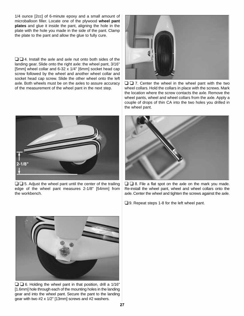
❏ ❏ 4. Install the axle and axle nut onto both sides of thelanding gear. Slide onto the right axle: the wheel pant, 3/16"[5mm] wheel collar and 6-32 x 1/4" [6mm] socket head capscrew followed by the wheel and another wheel collar andsocket head cap screw. Slide the other wheel onto the leftaxle. Both wheels must be on the axles to assure accuracyof the measurement of the wheel pant in the next step.
❏ ❏ 5. Adjust the wheel pant until the center of the trailingedge of the wheel pant measures 2-1/8" [54mm] from the workbench.
❏ ❏ 6. Holding the wheel pant in that position, drill a 1/16"[1.6mm] hole through each of the mounting holes in the landinggear and into the wheel pant. Secure the pant to the landinggear with two #2 x 1/2" [13mm] screws and #2 washers.
❏ ❏ 7. Center the wheel in the wheel pant with the twowheel collars. Hold the collars in place with the screws. Markthe location where the screw contacts the axle. Remove thewheel pants, wheel and wheel collars from the axle. Apply acouple of drops of thin CA into the two holes you drilled inthe wheel pant.
❏ ❏ 8. File a flat spot on the axle on the mark you made.Re-install the wheel pant, wheel and wheel collars onto theaxle. Center the wheel and tighten the screws against the axle.
❏ 9. Repeat steps 1-8 for the left wheel pant.
27

❏ 1. Cut the covering from the pushrod tube openings at therear of the fuselage. There are two located on the right sideand one located on the left. If you have trouble finding theopenings, slide a .074" x 36" [1.9 x 915mm] pushrod wireinto the tubes from inside of the fuselage, sliding it into thetube until it pushes the covering away from the fuselageslightly. This is where you should cut the covering away fromthe tubes.
❏ 2. Locate three .074" x 36" [1.9 x 915mm] pushrod wiresthreaded on one end. Thread a nylon clevis onto thethreaded end of each wire 20 full turns. Install a siliconeclevis keeper onto the clevis.
❏ 3. On the right side of the fuselage, slide one wire into theopening closest to the back of the fuselage. Install a nyloncontrol horn onto the clevis. Position the control horn on therudder, positioning it the same way you did with the ailerons.Mark the location for the screw holes. Drill through themarks you made with a 1/16" [1.6mm] drill bit, drilling onlyinto the plywood plate. Do not drill through the rudder!Install and then remove two 2-56 x 5/8" [16mm] machinescrews. Apply a couple drops of thin CA into the holes. Oncethe glue has cured, mount the horn and the nylon mountingplate to the rudder with the screws.
❏ 4. Install the two elevator pushrods using the sameprocedure used for the rudder. Be sure when installing thecontrol horn on the right elevator that you install it so it doesnot conflict with the rudder control horn.
❏ 5. Place your rudder servo into the servo tray as shown,positioning the last hole of the servo arm over the pushrodwire. Drill a 1/16" [1.6mm] hole through each of themounting holes. Remove the servo, then install and removea servo mounting screw into each hole. Apply a coupledrops of thin CA into the holes to harden the threads. Whenthe glue has cured, permanently mount the servo to theservo tray.
❏ 6. Center the rudder and the rudder servo, then install theservo arm. At the point the pushrod wire intersects the lasthole in the servo arm make a mark. Bend the wire 90degrees on that mark. Install a nylon Faslink and cut off theexcess wire the same as was done with the throttle servo.
❏ 7. Place your elevator servo into the servo tray as shown,positioning the last hole of the servo arm over the insidepushrod wire. Drill a 1/16" [1.6mm] hole through each of themounting holes. Remove the servo, then install and remove aservo mounting screw into each hole. Apply a couple drops ofthin CA into the holes to harden the threads.When the glue hascured permanently, mount the servo to the servo tray.
Install the Radio System
28
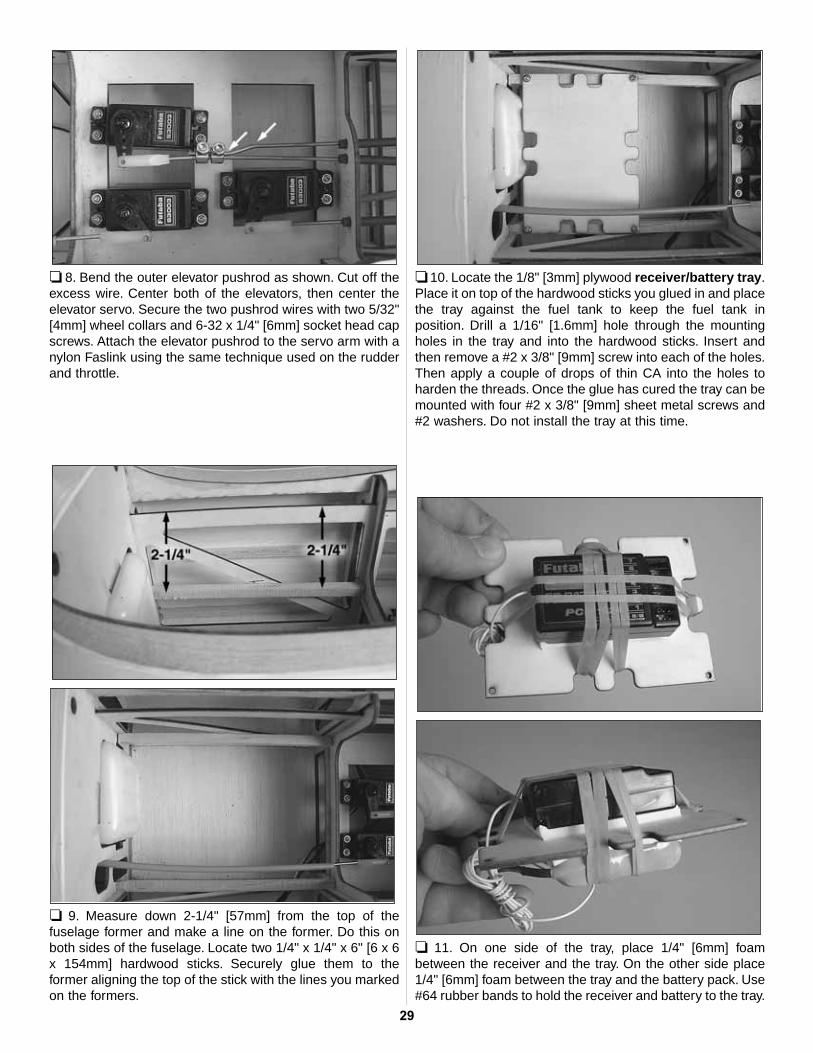
❏ 8. Bend the outer elevator pushrod as shown. Cut off theexcess wire. Center both of the elevators, then center theelevator servo. Secure the two pushrod wires with two 5/32"[4mm] wheel collars and 6-32 x 1/4" [6mm] socket head capscrews. Attach the elevator pushrod to the servo arm with anylon Faslink using the same technique used on the rudderand throttle.
❏ 9. Measure down 2-1/4" [57mm] from the top of thefuselage former and make a line on the former. Do this onboth sides of the fuselage. Locate two 1/4" x 1/4" x 6" [6 x 6x 154mm] hardwood sticks. Securely glue them to theformer aligning the top of the stick with the lines you markedon the formers.
❏ 10. Locate the 1/8" [3mm] plywood receiver/battery tray.Place it on top of the hardwood sticks you glued in and placethe tray against the fuel tank to keep the fuel tank inposition. Drill a 1/16" [1.6mm] hole through the mountingholes in the tray and into the hardwood sticks. Insert andthen remove a #2 x 3/8" [9mm] screw into each of the holes.Then apply a couple of drops of thin CA into the holes toharden the threads. Once the glue has cured the tray can bemounted with four #2 x 3/8" [9mm] sheet metal screws and#2 washers. Do not install the tray at this time.
❏ 11. On one side of the tray, place 1/4" [6mm] foambetween the receiver and the tray. On the other side place1/4" [6mm] foam between the tray and the battery pack. Use#64 rubber bands to hold the receiver and battery to the tray.
29
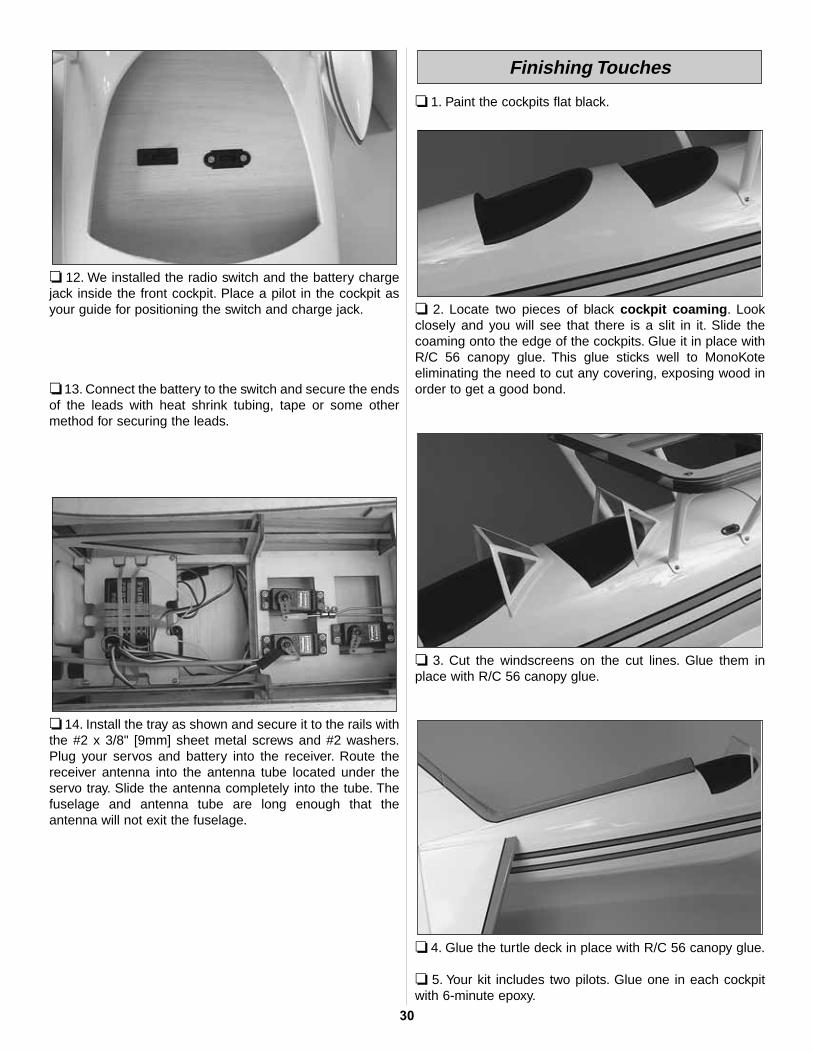
❏ 12. We installed the radio switch and the battery chargejack inside the front cockpit. Place a pilot in the cockpit asyour guide for positioning the switch and charge jack.
❏ 13. Connect the battery to the switch and secure the endsof the leads with heat shrink tubing, tape or some othermethod for securing the leads.
❏ 14. Install the tray as shown and secure it to the rails withthe #2 x 3/8" [9mm] sheet metal screws and #2 washers.Plug your servos and battery into the receiver. Route thereceiver antenna into the antenna tube located under theservo tray. Slide the antenna completely into the tube. Thefuselage and antenna tube are long enough that theantenna will not exit the fuselage.
❏ 1. Paint the cockpits flat black.
❏ 2. Locate two pieces of black cockpit coaming. Lookclosely and you will see that there is a slit in it. Slide thecoaming onto the edge of the cockpits. Glue it in place withR/C 56 canopy glue. This glue sticks well to MonoKoteeliminating the need to cut any covering, exposing wood inorder to get a good bond.
❏ 3. Cut the windscreens on the cut lines. Glue them inplace with R/C 56 canopy glue.
❏ 4. Glue the turtle deck in place with R/C 56 canopy glue.
❏ 5. Your kit includes two pilots. Glue one in each cockpitwith 6-minute epoxy.
Finishing Touches
30

❏ 6. Install the spinner with the prop appropriate to yourengine. The spinner includes a spinner nut that will fit theO.S.® .91 two-stroke and the 1.20 four-stroke engines. Thespinner bolt may be too long for some installations. Cut thebolt as needed to fit your particular application. Spinner nutsfor other engines are available from Great Planes, CBAssociates and True Turn.
The photos on the box show optional flying wires installedon the plane. The materials we used for this are notincluded in the kit but are readily available at any fabric storefor less than $10.00. The wires are made from an elasticcord typically used for sewing an elastic cuff in a sleeve. Thematerial is commonly called, “Beading Cord Elastic”.
You will need approximately seven yards, two smallpackages. The method described here will provide areasonably scale appearance without the hassles typicallyassociated with flying wires. Because they are made fromelastic there is no need to tension them each time you putthe plane together. These wires will add approximately twominutes to the overall assembly time of the plane at theflying field.
❏ ❏ 1. Measure from the fillet at the trailing edge of the stabout toward the tip of the stab 6-1/2" [165mm] and make amark with a felt-tip pen. Measure in from the trailing edge ofthe stab 1/4" [6mm] and make a crossing mark. Do thesame on the leading edge of the stab. Do this on both sidesof the stab.
❏ ❏ 2. At the rear corner of the fin, measure down and in1/8" [3mm]. From the intersection of those lines make amark on the front of the fin 3-1/8" [79mm]. On the marks,drill a hole through the fin with a 5/64" [2mm] drill.
❏ ❏ 3. Drill a 5/64" [2mm] hole through the block at the backof the fuselage.
Optional Flying Wire Installation
31

❏ ❏ 4. Cut a piece of the elastic cord 50" [1270mm] long.This length should be relaxed, not stretched. In order to feedthe elastic cord through the holes you have drilled, apply afew drops of thin CA to one end of the elastic cord, coveringapproximately 1" [25mm] of the cord. On the opposite end ofthe cord put a small drop of CA, just enough to make theend of the cord hard. On this end of the cord, apply a smalldrop of CA to the end and insert it into the hole in the block.Hold the cord in place until the glue cures. Thread theopposite end of the cord through the hole in the leadingedge of the stab as shown.
❏ ❏ 5. Thread the cord through the hole in the leading edgeof the fin.
❏ ❏ 6. Continue threading the cord through the hole in theleading edge of the stab on the opposite side of the fuselage.
❏ ❏ 7. At this point you will have to start stretching theelastic to complete the positioning of the elastic cord. Pullthe cord around the tail wheel wire, then thread the cordthrough the trailing edge of the stab and fin back to the holeyou drilled through in the block at the back of the fuselage.
❏ ❏ 8. Make two marks 1/2" [13mm] apart 1/4" [6mm]above the landing gear. Drill partially into the fuselage oneach of the four marks 5/64" [2mm].
32
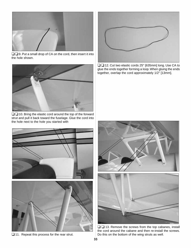
❏ ❏ 9. Put a small drop of CA on the cord, then insert it intothe hole shown.
❏ ❏ 10. Bring the elastic cord around the top of the forwardstrut and pull it back toward the fuselage. Glue the cord intothe hole next to the hole you started with
❏ 11. Repeat this process for the rear strut.
❏ ❏ 12. Cut two elastic cords 25" [635mm] long. Use CA toglue the ends together forming a loop. When gluing the endstogether, overlap the cord approximately 1/2" [13mm].
❏ ❏ 13. Remove the screws from the top cabanes, installthe cord around the cabane and then re-install the screws.Do this on the bottom of the wing struts as well.
33

❏ 14. This completes the wires for the right side. Repeatsteps 1-13 for the opposite side.
❏ 15. Make a mark identifying the top center of thefuselage. Mark four holes as shown. Drill partially into thefuselage with a 5/64" [2mm] drill on each of the four marks.
❏ 16. Cut four pieces of elastic cord 4" [100mm] long. Gluea cord into each of the four holes. Stretch the cord to the topof the cabane and glue the cord to the cabane with a smalldrop of CA.
The Stearman was primarily a fabric-covered aircraft, butthere were some panel lines along the top of the fuselage.In addition to the photographs on the box the followingpictures should help you in the placement of the decals.
❏ 1. Use scissors or a sharp hobby knife to cut the decalsfrom the sheet.
❏ 2. Be certain the model is clean and free from oilyfingerprints and dust. Prepare a dishpan or small bucket with amixture of liquid dish soap and warm water—about oneteaspoon of soap per gallon of water. Submerse the decal inthe soap and water and peel off the paper backing.Note: Even though the decals have a “sticky-back” and are notthe water transfer type, submersing them in soap & water allowsaccurate positioning and reduces air bubbles underneath.
❏ 3. Position decals on the model as shown on the boxcover. Holding the decal down, use a paper towel to wipemost of the water away.
❏ 4. Use a piece of soft balsa or something similar tosqueegee remaining water from under the decal. Apply therest of the decals the same way.
Apply the Decals
34
❏ 1. Turn on the transmitter and receiver and center thetrims. If necessary, remove the servo arms from the servosand reposition them so they are centered. Reinstall thescrews that hold on the servo arms.
❏ 2. With the transmitter and receiver still on, check all thecontrol surfaces to see if they are centered. If necessary, adjustthe clevises on the pushrods to center the control surfaces.
❏ 3. Make certain that the control surfaces and the carburetorrespond in the correct direction as shown in the diagram. If anyof the controls respond in the wrong direction, use the servoreversing in the transmitter to reverse the servos connected tothose controls. Be certain the control surfaces have remainedcentered. Adjust if necessary.
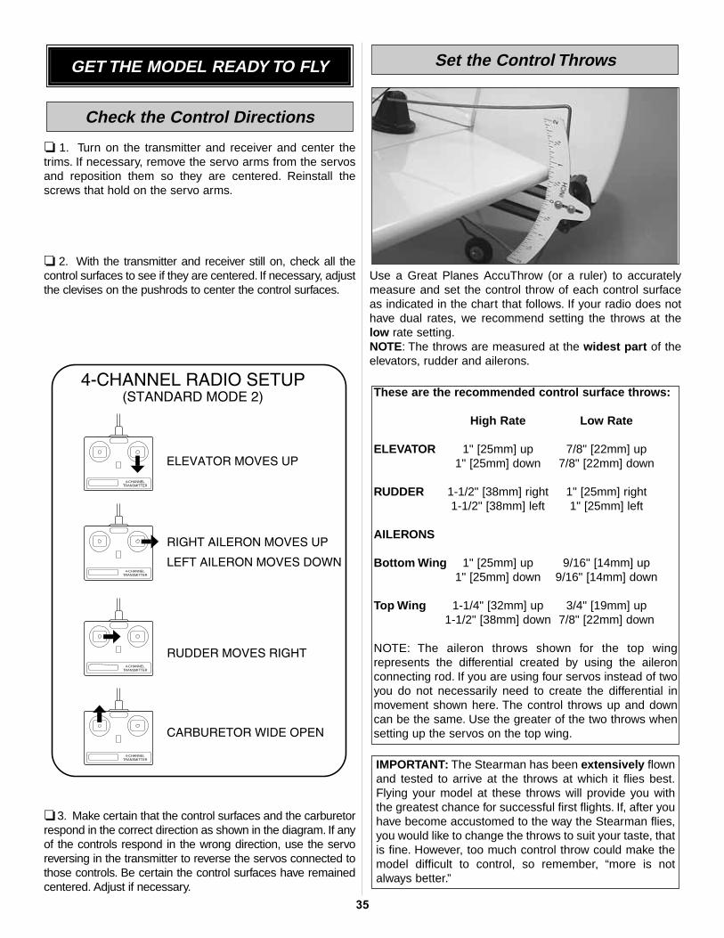
Use a Great Planes AccuThrow (or a ruler) to accuratelymeasure and set the control throw of each control surfaceas indicated in the chart that follows. If your radio does nothave dual rates, we recommend setting the throws at thelow rate setting.NOTE: The throws are measured at the widest part of theelevators, rudder and ailerons.
IMPORTANT: The Stearman has been extensively flownand tested to arrive at the throws at which it flies best.Flying your model at these throws will provide you withthe greatest chance for successful first flights. If, after youhave become accustomed to the way the Stearman flies,you would like to change the throws to suit your taste, thatis fine. However, too much control throw could make themodel difficult to control, so remember, “more is notalways better.”
These are the recommended control surface throws:
High Rate Low Rate
ELEVATOR 1" [25mm] up 7/8" [22mm] up1" [25mm] down 7/8" [22mm] down
RUDDER 1-1/2" [38mm] right 1" [25mm] right1-1/2" [38mm] left 1" [25mm] left
AILERONS
Bottom Wing 1" [25mm] up 9/16" [14mm] up1" [25mm] down 9/16" [14mm] down
Top Wing 1-1/4" [32mm] up 3/4" [19mm] up1-1/2" [38mm] down 7/8" [22mm] down
NOTE: The aileron throws shown for the top wingrepresents the differential created by using the aileronconnecting rod. If you are using four servos instead of twoyou do not necessarily need to create the differential inmovement shown here. The control throws up and downcan be the same. Use the greater of the two throws whensetting up the servos on the top wing.
Set the Control Throws
4-CHANNELTRANSMITTER
TRANSMITTER4-CHANNEL
TRANSMITTER4-CHANNEL
TRANSMITTER4-CHANNEL
Check the Control Directions
GET THE MODEL READY TO FLY
35
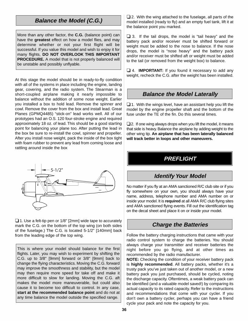
At this stage the model should be in ready-to-fly conditionwith all of the systems in place including the engine, landinggear, covering, and the radio system. The Stearman is ashort-coupled airplane making it nearly impossible tobalance without the addition of some nose weight. Earlieryou installed a box to hold lead. Remove the spinner andcowl. Remove the cover from the box and install lead. GreatPlanes (GPMQ4485) “stick-on” lead works well. All of ourprototypes had an O.S. 120 four-stroke engine and requiredapproximately 18 oz. of lead. This should be a good startingpoint for balancing your plane too. After putting the lead inthe box be sure to re-install the cowl, spinner and propeller.After you install nose weight, pack the inside of the box tightwith foam rubber to prevent any lead from coming loose andrattling around inside the box
❏ 1. Use a felt-tip pen or 1/8" [2mm] wide tape to accuratelymark the C.G. on the bottom of the top wing (on both sidesof the fuselage.) The C.G. is located 5-1/2" [140mm] backfrom the leading edge of the top wing.
❏ 2. With the wing attached to the fuselage, all parts of themodel installed (ready to fly) and an empty fuel tank, lift it atthe balance point you marked.
❏ 3. If the tail drops, the model is “tail heavy” and thebattery pack and/or receiver must be shifted forward orweight must be added to the nose to balance. If the nosedrops, the model is “nose heavy” and the battery packand/or receiver must be shifted aft or weight must be addedto the tail (or removed from the weight box) to balance.
❏ 4. IMPORTANT: If you found it necessary to add anyweight, recheck the C.G. after the weight has been installed.
❏ 1. With the wings level, have an assistant help you lift themodel by the engine propeller shaft and the bottom of thefuse under the TE of the fin. Do this several times.
❏ 2. If one wing always drops when you lift the model, it meansthat side is heavy. Balance the airplane by adding weight to theother wing tip. An airplane that has been laterally balancedwill track better in loops and other maneuvers.
No matter if you fly at an AMA sanctioned R/C club site or if youfly somewhere on your own, you should always have yourname, address, telephone number and AMA number on orinside your model. It is required at all AMA R/C club flying sitesand AMA sanctioned flying events. Fill out the identification tagon the decal sheet and place it on or inside your model.
Follow the battery charging instructions that came with yourradio control system to charge the batteries. You shouldalways charge your transmitter and receiver batteries thenight before you go flying, and at other times asrecommended by the radio manufacturer.NOTE: Checking the condition of your receiver battery packis highly recommended. All battery packs, whether it’s atrusty pack you’ve just taken out of another model, or a newbattery pack you just purchased, should be cycled, notingthe discharge capacity. Oftentimes, a weak battery pack canbe identified (and a valuable model saved!) by comparing itsactual capacity to its rated capacity. Refer to the instructionsand recommendations that come with your cycler. If youdon’t own a battery cycler, perhaps you can have a friendcycle your pack and note the capacity for you.
Charge the Batteries
Identify Your Model
PREFLIGHT
Balance the Model Laterally
This is where your model should balance for the firstflights. Later, you may wish to experiment by shifting theC.G. up to 3/8" [9mm] forward or 3/8" [9mm] back tochange the flying characteristics. Moving the C.G. forwardmay improve the smoothness and stability, but the modelmay then require more speed for take off and make itmore difficult to slow for landing. Moving the C.G. aftmakes the model more maneuverable, but could alsocause it to become too difficult to control. In any case,start at the recommended balance point and do not atany time balance the model outside the specified range.
More than any other factor, the C.G. (balance point) canhave the greatest effect on how a model flies, and maydetermine whether or not your first flight will besuccessful. If you value this model and wish to enjoy it formany flights, DO NOT OVERLOOK THIS IMPORTANTPROCEDURE. A model that is not properly balanced willbe unstable and possibly unflyable.
Balance the Model (C.G.)
36
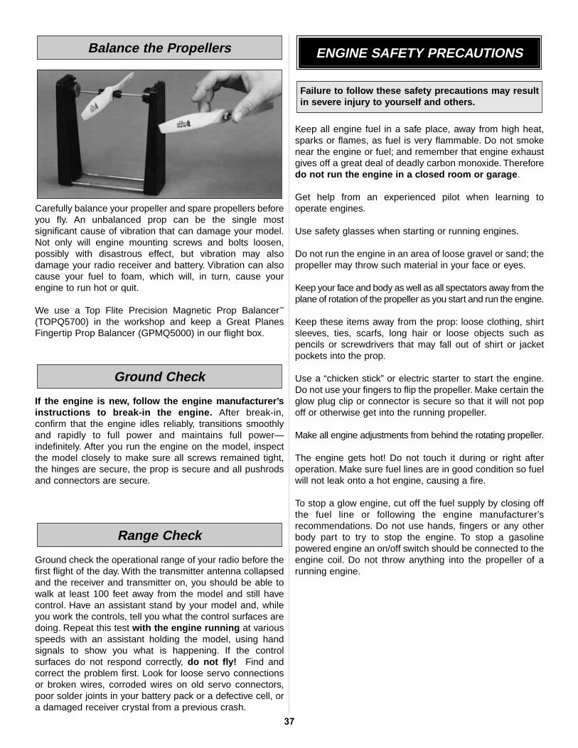
Carefully balance your propeller and spare propellers beforeyou fly. An unbalanced prop can be the single mostsignificant cause of vibration that can damage your model.Not only will engine mounting screws and bolts loosen,possibly with disastrous effect, but vibration may alsodamage your radio receiver and battery. Vibration can alsocause your fuel to foam, which will, in turn, cause yourengine to run hot or quit.
We use a Top Flite Precision Magnetic Prop Balancer™
(TOPQ5700) in the workshop and keep a Great PlanesFingertip Prop Balancer (GPMQ5000) in our flight box.
If the engine is new, follow the engine manufacturer’sinstructions to break-in the engine. After break-in,confirm that the engine idles reliably, transitions smoothlyand rapidly to full power and maintains full power—indefinitely. After you run the engine on the model, inspectthe model closely to make sure all screws remained tight,the hinges are secure, the prop is secure and all pushrodsand connectors are secure.
Ground check the operational range of your radio before thefirst flight of the day. With the transmitter antenna collapsedand the receiver and transmitter on, you should be able towalk at least 100 feet away from the model and still havecontrol. Have an assistant stand by your model and, whileyou work the controls, tell you what the control surfaces aredoing. Repeat this test with the engine running at variousspeeds with an assistant holding the model, using handsignals to show you what is happening. If the controlsurfaces do not respond correctly, do not fly! Find andcorrect the problem first. Look for loose servo connectionsor broken wires, corroded wires on old servo connectors,poor solder joints in your battery pack or a defective cell, ora damaged receiver crystal from a previous crash.
Keep all engine fuel in a safe place, away from high heat,sparks or flames, as fuel is very flammable. Do not smokenear the engine or fuel; and remember that engine exhaustgives off a great deal of deadly carbon monoxide. Thereforedo not run the engine in a closed room or garage.
Get help from an experienced pilot when learning to operate engines.
Use safety glasses when starting or running engines.
Do not run the engine in an area of loose gravel or sand; thepropeller may throw such material in your face or eyes.
Keep your face and body as well as all spectators away from theplane of rotation of the propeller as you start and run the engine.
Keep these items away from the prop: loose clothing, shirtsleeves, ties, scarfs, long hair or loose objects such aspencils or screwdrivers that may fall out of shirt or jacketpockets into the prop.
Use a “chicken stick” or electric starter to start the engine.Do not use your fingers to flip the propeller. Make certain theglow plug clip or connector is secure so that it will not popoff or otherwise get into the running propeller.
Make all engine adjustments from behind the rotating propeller.
The engine gets hot! Do not touch it during or right afteroperation. Make sure fuel lines are in good condition so fuelwill not leak onto a hot engine, causing a fire.
To stop a glow engine, cut off the fuel supply by closing offthe fuel line or following the engine manufacturer’srecommendations. Do not use hands, fingers or any otherbody part to try to stop the engine. To stop a gasolinepowered engine an on/off switch should be connected to theengine coil. Do not throw anything into the propeller of arunning engine.
Failure to follow these safety precautions may resultin severe injury to yourself and others.
ENGINE SAFETY PRECAUTIONS
Range Check
Ground Check
Balance the Propellers
37
Read and abide by the following Academy of ModelAeronautics Official Safety Code:
GENERAL
1. I will not fly my model aircraft in sanctioned events, airshows, or model flying demonstrations until it has beenproven to be airworthy by having been previouslysuccessfully flight tested.
2. I will not fly my model aircraft higher than approximately400 feet within 3 miles of an airport without notifying theairport operator. I will give right of way to, and avoid flyingin the proximity of full scale aircraft. Where necessary anobserver shall be used to supervise flying to avoid havingmodels fly in the proximity of full scale aircraft.
3. Where established, I will abide by the safety rules for theflying site I use, and I will not willfully and deliberately fly mymodels in a careless, reckless and/or dangerous manner.
7. I will not fly my model unless it is identified with myname and address or AMA number, on or in the model.
9. I will not operate models with pyrotechnics (any devicethat explodes, burns, or propels a projectile of any kind).
RADIO CONTROL
1. I will have completed a successful radio equipmentground check before the first flight of a new or repairedmodel.2. I will not fly my model aircraft in the presence ofspectators until I become a qualified flier, unless assisted byan experienced helper.
3. I will perform my initial turn after takeoff away from thepit or spectator areas, and I will not thereafter fly over pit orspectator areas, unless beyond my control.
4. I will operate my model using only radio controlfrequencies currently allowed by the FederalCommunications Commission...
Since the Stearman qualifies as a “giant scale” modeland is therefore eligible to fly in IMAA events, we’veincluded excerpts from the IMAA Safety Code.
Definition: For the purpose of the following IMAA SafetyCode, the term Giant Scale shall refer to radio controlledmodel aircraft, either scale or non-scale, which have awingspan of 80 inches or more for monoplanes and 60inches or more for multi-winged model aircraft and have aramp weight (fueled and ready to fly) of 55 lbs. or less.
Section 1.0: SAFETY STANDARD1.1 Adherence to Code:This safety code is to be strictly followed
1.2 The most current AMA Safety Code in effect is to beobserved. However, the competition sections of the codemay be disregarded.
Section 3.0: Safety Check3.4 Flight Testing: All Giant Scale R/C aircraft are to havebeen flight tested and flight trimmed with a minimum of sixflights before the model is allowed to fly at an IMAASanctioned event.
3.5 Proof of Flight: The completing and signing of theDeclaration section of the Safety Inspection form by the pilot(or owner) shall document as fact that each aircraft hasbeen successfully flight-tested and proven airworthy prior toan IMAA event.
Section 5.0: EMERGENCY ENGINE SHUT OFF (kill switch)5.1 All magneto spark ignition engines must have a coilgrounding switch on the aircraft to stop the engine.This will alsoprevent accidental starting of the engine. This switch shall bereadily available to both pilot and helper. This switch is to beoperated manually and without the use of the radio system.
5.2 Engines with battery power ignition systems must have aswitch to turn off the power from the battery pack to disable theengine from firing.This will also prevent accidental starting of theengine. This switch shall be readily available to both pilot andhelper. This switch shall be operated manually and without theuse of the Radio System.
5.3 There must also be a means to stop the engine from thetransmitter. The most common method is to close thecarburetor throat completely using throttle trim, however,other methods are acceptable. This requirement applies toall glow/gas ignition engines regardless of size.
Section 6.0: RADIO REQUIREMENTS6.1 All transmitters must be FCC type certified.
6.2 FCC Technician or higher-class license required for 6meter band operation only.
IMAA SAFETY CODE (excerpts)AMA SAFETY CODE (excerpts)
38

❏ 1. Fuelproof all areas exposed to fuel or exhaustresidue such as the cowl ring, cowl mounting blocks,wing saddle area, etc.
❏ 2. Check the C.G. according to the measurementsprovided in the manual.
❏ 3. Be certain the battery and receiver are securelymounted in the fuse. Simply stuffing them into placewith foam rubber is not sufficient.
❏ 4. Extend your receiver antenna and make sure is inthe antenna tube..
❏ 5. Balance your model laterally.❏ 6. Use threadlocking compound to secure critical
fasteners such as the set screws that hold the wheelaxles to the struts, screws that hold the carburetor arm(if applicable), screw-lock pushrod connectors, etc.
❏ 7. Add a drop of oil to the wheel axles.❏ 8. Make sure all hinges are securely glued in place.❏ 9. Reinforce holes for wood screws with thin CA where
appropriate (servo mounting screws, cowl mountingscrews, etc.).
❏ 10. Confirm that all controls operate in the correct directionand the throws are set up according to the manual.
❏ 11. Make sure there are silicone retainers on all theclevises and that all servo arms are secured to theservos with the screws included with your radio.
❏ 12. Secure connections between servo wires and Y-connectors or servo extensions, and theconnection between your battery pack and theon/off switch with vinyl tape, heat shrink tubing orspecial clips suitable for that purpose.
❏ 13. Make sure any servo extension cords you may haveused do not interfere with other systems (servoarms, pushrods, etc.).
❏ 14. Secure the pressure tap (if used) to the muffler withhigh temp RTV silicone, thread locking compound orJ.B. Weld.
❏ 15. Make sure the fuel lines are connected and not kinked.❏ 16. Balance your propeller (and spare propellers).❏ 17. Tighten the propeller nut and spinner.❏ 18. Place your name, address, AMA number and
telephone number on or inside your model.❏ 19. Cycle your receiver battery pack (if necessary) and
make sure it is fully charged.❏ 20. If you wish to photograph your model, do so before
your first flight.❏ 21. Range check your radio when you get to the flying field.❏ 22. Make sure all wing attachment bolts and screws are
securely tightened.
A fully cowled engine may run at a higher temperature thanan un-cowled engine. For this reason, the fuel mixtureshould be richened so the engine runs at about 200 rpmbelow peak speed. By running the engine slightly rich, youwill help prevent dead-stick landings caused by overheating.
Before you get ready to take off, see how the model handleson the ground by doing a few practice runs at low speedson the runway. Hold “up” elevator to keep the tail wheel onthe ground. If necessary, adjust the tail wheel so the modelwill roll straight down the runway. If you need to calm yournerves before the maiden flight, shut the engine down andbring the model back into the pits. Top off the fuel, thencheck all fasteners and control linkages for peace of mind.
Remember to take off into the wind. When you’re ready,point the model straight down the runway, hold a bit of upelevator to keep the tail on the ground to maintain tail wheelsteering, and then gradually advance the throttle. As the
Take Off
CAUTION (THIS APPLIES TO ALL R/C AIRPLANES): If,while flying, you notice an alarming or unusual soundsuch as a low-pitched “buzz,” this may indicate controlsurface flutter. Flutter occurs when a control surface(such as an aileron or elevator) or a flying surface (suchas a wing or stab) rapidly vibrates up and down (thuscausing the noise). In extreme cases, if not detectedimmediately, flutter can actually cause the control surfaceto detach or the flying surface to fail, thus causing loss ofcontrol followed by an impending crash. The best thing todo when flutter is detected is to slow the modelimmediately by reducing power, then land as soon assafely possible. Identify which surface fluttered (so theproblem may be resolved) by checking all the servogrommets for deterioration or signs of vibration. Makecertain all pushrod linkages are secure and free of play. Ifit fluttered once, under similar circumstances it willprobably flutter again unless the problem is fixed. Somethings which can cause flutter are; Excessive hinge gap;Not mounting control horns solidly; Poor fit of clevis pin inhorn; Side-play of wire pushrods caused by large bends;Excessive free play in servo gears; Insecure servomounting; and one of the most prevalent causes of flutter;Flying an over-powered model at excessive speeds.
Fuel Mixture Adjustments
FLYINGCHECK LISTDuring the last few moments of preparation your mind maybe elsewhere anticipating the excitement of the first flight.Because of this, you may be more likely to overlook certainchecks and procedures that should be performed before themodel is flown. To help avoid this, a checklist is provided tomake sure these important areas are not overlooked. Manyare covered in the instruction manual, so where appropriate,refer to the manual for complete instructions. Be sure tocheck the items off as they are completed.
39
model gains speed, decrease up elevator allowing the tail tocome off the ground. One of the most important things toremember with a tail dragger is to always be ready to applyright rudder to counteract engine torque. Gain as muchspeed as your runway and flying site will practically allowbefore gently applying up elevator, lifting the model into theair. At this moment it is likely that you will need to apply moreright rudder to counteract engine torque. Be smooth on theelevator stick, allowing the model to establish a gentle climbto a safe altitude before turning into the traffic pattern.
For reassurance and to keep an eye on other traffic, it is agood idea to have an assistant on the flight line with you. Tellhim to remind you to throttle back once the plane gets to acomfortable altitude.While full throttle is usually desirable fortake off, most models fly more smoothly at reduced speeds.
Take it easy with the Super Stearman for the first few flights,gradually getting acquainted with it as you gain confidence.Adjust the trims to maintain straight and level flight. Afterflying around for a while, and while still at a safe altitude withplenty of fuel, practice slow flight and execute practicelanding approaches by reducing the throttle to see how themodel handles at slower speeds. Add power to see how sheclimbs as well. Continue to fly around, executing variousmaneuvers and making mental notes (or having yourassistant write them down) of what trim or C.G. changesmay be required to fine tune the model so it flies the way youlike. Mind your fuel level, but use this first flight to becomefamiliar with your model before landing.
To initiate a landing approach, lower the throttle while on thedownwind leg. Allow the nose of the model to pitchdownward to gradually bleed off altitude. Continue to losealtitude, but maintain airspeed by keeping the nose down asyou turn onto the crosswind leg. Make your final turn towardthe runway (into the wind) keeping the nose down tomaintain airspeed and control. Level the attitude when themodel reaches the runway threshold, modulating the throttleas necessary to maintain your glide path and airspeed. Ifyou are going to overshoot, smoothly advance the throttle(always ready on the right rudder to counteract torque) andclimb out to make another attempt. When you’re ready tomake your landing flare and the model is a foot or so off thedeck, smoothly increase up elevator until it gently touchesdown. Once the model is on the runway and has lost flyingspeed, hold up elevator to place the tail on the ground,regaining tail wheel control.
One final note about flying your model. Have a goal or flightplan in mind for every flight. This can be learning a newmaneuver(s), improving a maneuver(s) you already know, or
learning how the model behaves in certain conditions (suchas on high or low rates). This is not necessarily to improveyour skills (though it is never a bad idea!), but moreimportantly so you do not surprise yourself by impulsivelyattempting a maneuver and suddenly finding that you’ve runout of time, altitude or airspeed. Every maneuver should bedeliberate, not impulsive. For example, if you’re going to doa loop, check your altitude, mind the wind direction(anticipating rudder corrections that will be required tomaintain heading), remember to throttle back at the top, andmake certain you are on the desired rates (high/low rates).A flight plan greatly reduces the chances of crashing yourmodel just because of poor planning and impulsive moves.Remember to think.
Have a ball! But always stay in control and fly in a safe manner.
GOOD LUCK AND GREAT FLYING!
Landing
Flight
40

![INSTRUCTION MANUAL - Hobbicomanuals.hobbico.com/gpm/gpma1030-manual.pdf · · 2013-04-26in this instruction manual. All components must be correctly ... 1/16" [1.6mm], 5/64" [2mm],](https://img.pdfslide.net/doc/110x75/5aa46d307f8b9a2f048c2578/instruction-manual-this-instruction-manual-all-components-must-be-correctly-.jpg)