Embed Size (px)
Citation preview
V1300X-DVC & V1300X-RVCIntelligent Remote Control Panels
Instruction Manual
Vicon Part No. 8006-8777-08-00 Rev 1202 Section 9
VICON INDUSTRIES INC., 89 ARKAY DRIVE, HAUPPAUGE, NEW YORK 11788TEL: 631-952-CCTV (2288) FAX: 631-951-CCTV (2288) TOLL FREE: 800-645-9116
24-Hour Technical Support: 800-34-VICON (800-348-4266)UK: 44/(0) 1489-566300 INFOFAX: 800-287-1207 WEB: www.vicon-cctv.com
Vicon Industries Inc. does not warrant that the functions contained in thisequipment will meet your requirements or that the operation will be entirelyerror free or perform precisely as described in the documentation. Thissystem has not been designed to be used in life-critical situations andmust not be used for this purpose.
Copyright © 2002 Vicon Industries Inc. All rights reserved.Product specifications subject to change without notice.Vicon and its logo are registered trademarks of Vicon Industries Inc.

X777-08 Rev 1202 Intelligent Remote Control Panels Contents • i
Contents Introduction .........................................................................................................................1 Installation ...........................................................................................................................2
Determine the System Configuration (Keypad Type) .................................................................................2 Summary .........................................................................................................................................................4 MSYS, 1300 & 1200 Configurations..............................................................................................................4
Standalone Configuration ..................................................................................................5 RS-485 End-of-Line Termination...................................................................................................................6
Programming.......................................................................................................................6 Logging On & Off............................................................................................................................................6 Keypad Type ...................................................................................................................................................6 Speed Control Type........................................................................................................................................7 Receiver Function Inhibit ..............................................................................................................................7 Joystick Response Profile.............................................................................................................................8 Keypad Addresses .........................................................................................................................................9 Keypad Baud Rates........................................................................................................................................9 Passcodes.....................................................................................................................................................10 Auto Logout ..................................................................................................................................................10 Defaults .........................................................................................................................................................11
Operation ...........................................................................................................................11 Alarms ...........................................................................................................................................................11 Auxiliary Function Control ..........................................................................................................................12 Communication Failures .............................................................................................................................12 Crosspoint Reset..........................................................................................................................................12 Lens Operation .............................................................................................................................................12 Manual Switching .........................................................................................................................................12 Macros ...........................................................................................................................................................13 Presets...........................................................................................................................................................13 Sequential Switching ...................................................................................................................................13 Tours and Salvos..........................................................................................................................................14 Using the Joystick........................................................................................................................................14
Diagnostics........................................................................................................................15 Maintenance ......................................................................................................................16
Defining the Joystick Control Range .........................................................................................................16 Fuse Replacement........................................................................................................................................17
Reference...........................................................................................................................17 Keypad Messages ........................................................................................................................................17
Technical Information.......................................................................................................18 Shipping Instructions .......................................................................................................19

ii • Contents X777-08 Rev 1202 Intelligent Remote Control Panels
This page intentionally left blank.
X777-08 Rev 1202 Intelligent Remote Control Panels Introduction • 1
Introduction Note: Read all of the instructions completely before installing or operating this equipment. The information in this manual covers installation, programming and operation for the V1300X-DVC and V1300X-RVC Intelligent Remote Control Panels. The installation procedures should only be performed by a qualified technician using approved materials in accordance with national, state and local wiring codes. The unit complies with FCC standards for a Class A device and with European Community EMC Directive 89/336. The product was subjected to the testing outlined in European Normalization Standard EN 50081-1 (Electromagnetic Compatibility - General Emissions Standard Part 1: Residential, Commercial and Light Industry), and EN 50082-1 (Electromagnetic Compatibility - Generic Immunity Standard Part 1: Residential, Commercial, and Light Industry).
Note: Throughout this manual the terms “keypad” and “remote control panel” are used interchangeably. The intelligent remote control panel is a multifunction keypad. It is front-panel programmable, allowing modification to keypad/receiver communications baud rates, keypad operational mode, keypad address and passcodes from the keypad. The keypad features a pan-and-tilt joystick which can be set for variable- or fixed-speed operation. It also offers pushbutton control for the following operations and key input buffering for faster system response.
• camera and monitor selection • lens speed
• zoom, focus, iris • receiver preset position entry
• autopan • alarm acknowledgment
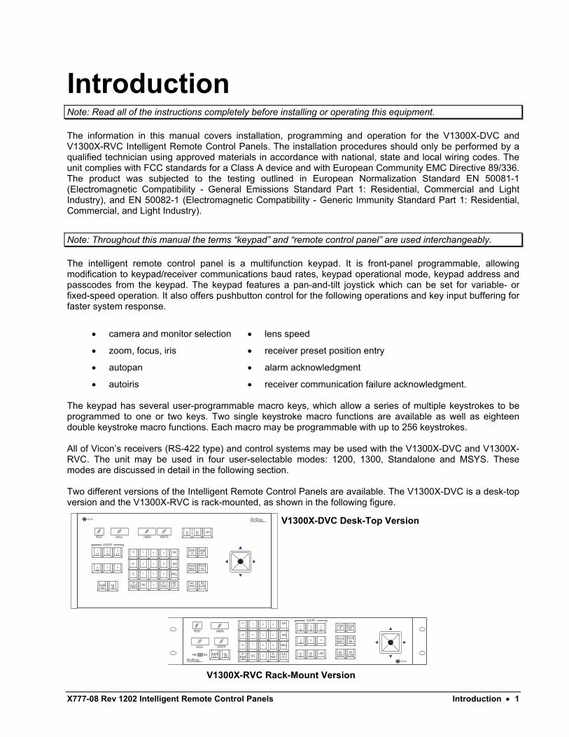
• autoiris • receiver communication failure acknowledgment. The keypad has several user-programmable macro keys, which allow a series of multiple keystrokes to be programmed to one or two keys. Two single keystroke macro functions are available as well as eighteen double keystroke macro functions. Each macro may be programmable with up to 256 keystrokes. All of Vicon’s receivers (RS-422 type) and control systems may be used with the V1300X-DVC and V1300X-RVC. The unit may be used in four user-selectable modes: 1200, 1300, Standalone and MSYS. These modes are discussed in detail in the following section. Two different versions of the Intelligent Remote Control Panels are available. The V1300X-DVC is a desk-top version and the V1300X-RVC is rack-mounted, as shown in the following figure.
V 1300P S
STATUS MONITORCAMERAPRESET
OUTINZOOMZOOM
FARFOCUS
NEARFOCUS
CLOSEOPENIRISIRIS
OUTPASSENTERPP
SEQ 0BY RUB
F3
7 8 9
DWELL
F2 4 5 6 MON
CAM
321
F1
FAILALARM
321
AUXILIARY
654
L-SPDA/PA/I
V 1300P S
L-SPD CLOSEOPEN
FARFOCUS
NEARFOCUS
OUTIN
FAILALARMIRISIRIS
ZOOMZOOM
A/PA/I
654
321
AUXILIARY
RUNPGM
MONITORSTATUS
CAMERAPRESET
OUTPASSENTERPP
SEQ 0BY RUB
F3
7 8 9
DWELL
F2 4 5 6 MON
CAM
321
F1
V1300X-DVC Desk-Top Version
V1300X-RVC Rack-Mount Version
2 • Installation X777-08 Rev 1202 Intelligent Remote Control Panels
Installation Warning: Do not apply power to any unit until all connections are properly made.
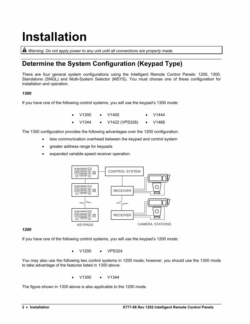
Determine the System Configuration (Keypad Type) There are four general system configurations using the Intelligent Remote Control Panels: 1200, 1300, Standalone (SNGL) and Multi-System Selector (MSYS). You must choose one of these configuration for installation and operation. 1300 If you have one of the following control systems, you will use the keypad’s 1300 mode:
• V1300 • V1400 • V1444
• V1344 • V1422 (VPS328) • V1466 The 1300 configuration provides the following advantages over the 1200 configuration:
• less communication overhead between the keypad and control system
• greater address range for keypads
• expanded variable-speed receiver operation.
CAMERA STATIONSKEYPADS
CONTROL SYSTEM
RECEIVER
RECEIVER
1200 If you have one of the following control systems, you will use the keypad’s 1200 mode:
• V1200 • VPS324 You may also use the following two control systems in 1200 mode; however, you should use the 1300 mode to take advantage of the features listed in 1300 above.
• V1300 • V1344 The figure shown in 1300 above is also applicable to the 1200 mode.
X777-08 Rev 1202 Intelligent Remote Control Panels Installation • 3
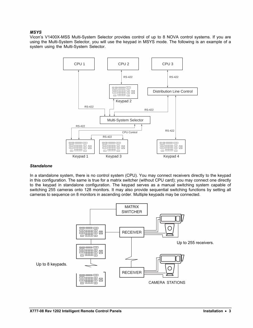
MSYS Vicon’s V1400X-MSS Multi-System Selector provides control of up to 8 NOVA control systems. If you are using the Multi-System Selector, you will use the keypad in MSYS mode. The following is an example of a system using the Multi-System Selector.
CPU 1
Distribution Line Control
Multi-System Selector
CPU 2 CPU 3
Keypad 2
Keypad 1 Keypad 3 Keypad 4
RS-422
RS-422RS-422
RS-422
RS-422
RS-422
CPU Control
RS-422
Standalone In a standalone system, there is no control system (CPU). You may connect receivers directly to the keypad in this configuration. The same is true for a matrix switcher (without CPU card); you may connect one directly to the keypad in standalone configuration. The keypad serves as a manual switching system capable of switching 255 cameras onto 128 monitors. It may also provide sequential switching functions by setting all cameras to sequence on 8 monitors in ascending order. Multiple keypads may be connected.
Up to 255 receivers.
Up to 8 keypads.
4 • Installation X777-08 Rev 1202 Intelligent Remote Control Panels
Summary The first step in the installation and operation of the keypad is to determine the system mode, or configuration, as discussed in the previous section. To summarize, you will choose a mode using the following guidelines.
If you have… then the appropriate configuration is…
• V1200, VPS324 control systems • 1200
• V1300, V1344, V1400, V1422 (VPS328), V1444, V1466 control systems
• 1300 (you may use 1200 for V1300 and V1344 with limitations noted in the previous section)
• no control system (use keypad to switch cameras to monitors)
• Standalone
• V1400X-MSS Multi-System Selector • MSYS In the Programming chapter, you will choose a configuration for the Keypad Type parameter.
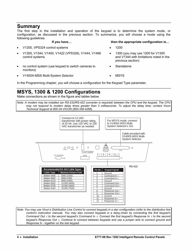
MSYS, 1300 & 1200 Configurations Make connections as shown in the figure and tables below.
Note: A modem may be installed (an RS-232/RS-422 converter is required) between the CPU and the keypad. The CPU may not respond to modem delay times greater than 3 milliseconds. To adjust the delay time, contact Vicon Technical Support at 800-34-VICON (800-348-4266).
AUXPGM
RS-232/RS485
10-12VAC/2A/60HZCLASS 2 WIRING
RUN
J29 J1
J20
SW39
2A 120V3AG
CAUTIONRISK OF FIRE
REPLACE FUSEAS MARKED
Cable provided with V1400X-MSS Multi-System Selector.
For MSYS mode, connect to V1400X-MSS Multi-System Selector's J10.
1 2 3 4 5 6 7 8 9 10 11 12
Pin No. Keypad Signals
1� Ground2 � Command In –3 � Command In +4 � Ground5 � Command Out –6 � Command Out +7 � Ground8 � Response Out –9 � Response Out +10 � Ground11 � Response In –12 � Response In +
Cable TypeRecommended RS-422 Cable Types
Maximum Distance ft (m)Belden 9406 � 5000 (1500)Belden 9402 � 5000 (1500Belden 8723 � 8000 (2400)Belden 8162 � 15,000 (4600)Belden 9729 � 15,000 (4600)Belden 9182 � 25,000 (7600)
Connect to 12 VAC transformer with power rating of 20 VA. Use 120 VAC or 230 VAC transformer as needed.
Note: You may use Vicon’s Distribution Line Control to connect keypads in a star configuration (refer to the distribution line
control’s instruction manual). You may also connect keypads in a daisy-chain by connecting the first keypad’s Command Out ± to the second keypad’s Command In ±. Connect the first keypad’s Response In ± to the second keypad’s Response Out ±. Continue to connect between keypads and use a jumper wire to connect ground and Response In - together on the last keypad.
RS-422
X777-08 Rev 1202 Intelligent Remote Control Panels Standalone Configuration • 5
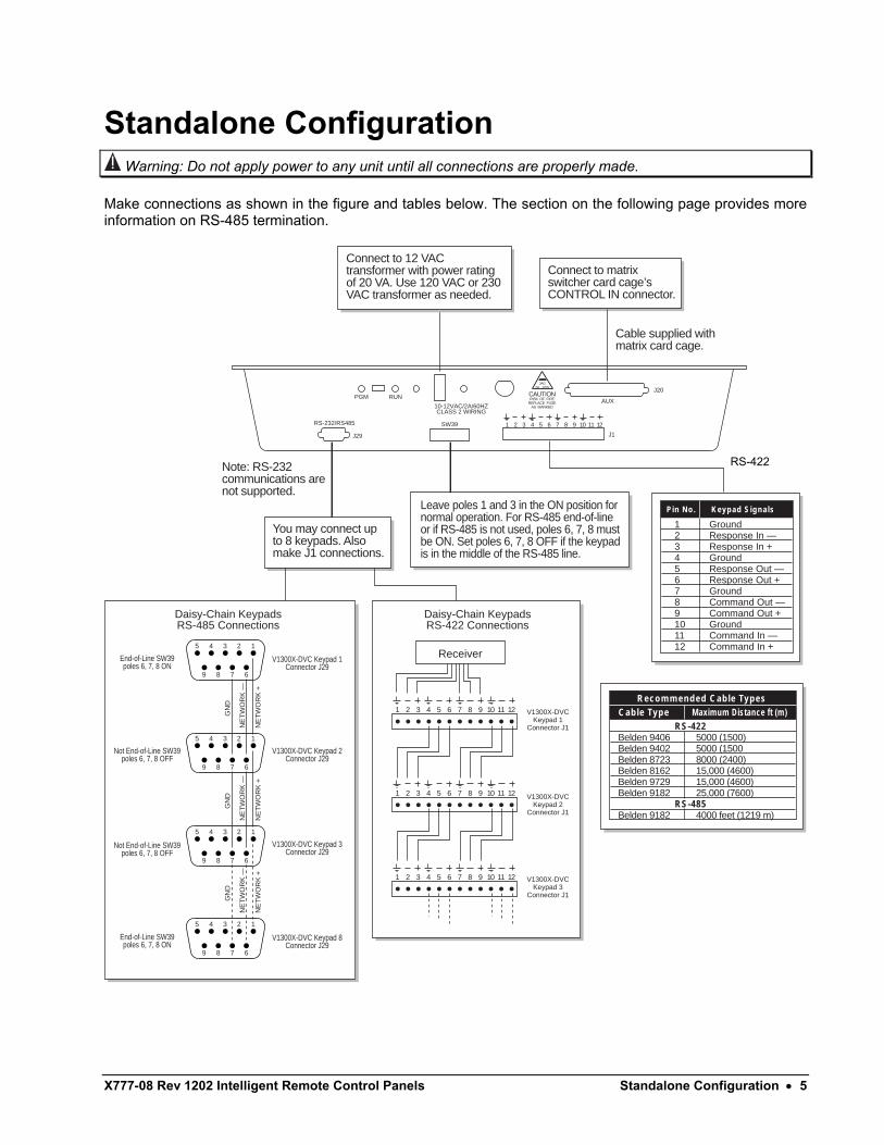
Standalone Configuration Warning: Do not apply power to any unit until all connections are properly made.
Make connections as shown in the figure and tables below. The section on the following page provides more information on RS-485 termination.
AUXPGM
RS-232/RS485
10-12VAC/2A/60HZCLASS 2 WIRING
RUN
J29 J1
J20
SW39
2A 120V3AG
CAUTIONRISK OF FIRE
REPLACE FUSEAS MARKED
Note: RS-232 communications are not supported.
Cable supplied with matrix card cage.
Connect to matrix switcher card cage’s CONTROL IN connector.
You may connect up to 8 keypads. Also make J1 connections.
Leave poles 1 and 3 in the ON position for normal operation. For RS-485 end-of-line or if RS-485 is not used, poles 6, 7, 8 must be ON. Set poles 6, 7, 8 OFF if the keypad is in the middle of the RS-485 line.
Pin No. Keypad Signals
1� Ground2 � Response In —3 � Response In +4 � Ground5 � Response Out —6 � Response Out +7 � Ground8 � Command Out —9 � Command Out +10 � Ground11 � Command In —12 � Command In +
Cable TypeRecommended Cable Types
Maximum Distance ft (m) RS-422�Belden 9406 � 5000 (1500)Belden 9402 � 5000 (1500Belden 8723 � 8000 (2400)Belden 8162 � 15,000 (4600)Belden 9729 � 15,000 (4600)Belden 9182 � 25,000 (7600) RS-485Belden 9182 � 4000 feet (1219 m)
Daisy-Chain KeypadsRS-485 Connections
9 8 7 6
12345
End-of-Line SW39poles 6, 7, 8 ON
Not End-of-Line SW39poles 6, 7, 8 OFF
Not End-of-Line SW39poles 6, 7, 8 OFF
End-of-Line SW39poles 6, 7, 8 ON
9 8 7 6
12345
V1300X-DVC Keypad 2Connector J29
V1300X-DVC Keypad 1Connector J29
GN
D
NE
TW
OR
K —
NE
TW
OR
K +
9 8 7 6
12345
V1300X-DVC Keypad 3Connector J29
V1300X-DVC Keypad 8Connector J29
GN
D
NE
TW
OR
K —
NE
TW
OR
K +
9 8 7 6
12345
GN
D
NE
TW
OR
K —
NE
TW
OR
K +
1 2 3 4 5 6 7 8 9 10 11 12
Daisy-Chain KeypadsRS-422 Connections
V1300X-DVCKeypad 1
Connector J1
V1300X-DVCKeypad 2
Connector J1
V1300X-DVCKeypad 3
Connector J1
1 2 3 4 5 6 7 8 9 10 11 12
1 2 3 4 5 6 7 8 9 10 11 12
1 2 3 4 5 6 7 8 9 10 11 12
Receiver
Connect to 12 VAC transformer with power rating of 20 VA. Use 120 VAC or 230 VAC transformer as needed.
RS-422
6 • Programming X777-08 Rev 1202 Intelligent Remote Control Panels
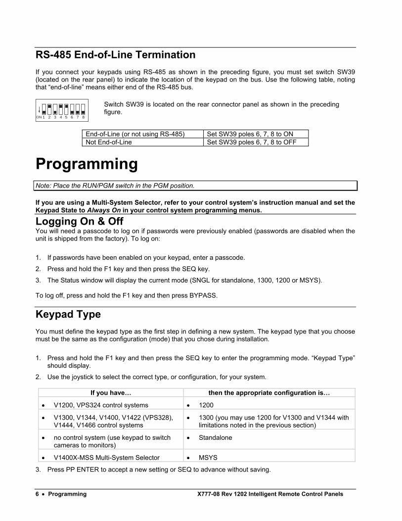
RS-485 End-of-Line Termination If you connect your keypads using RS-485 as shown in the preceding figure, you must set switch SW39 (located on the rear panel) to indicate the location of the keypad on the bus. Use the following table, noting that “end-of-line” means either end of the RS-485 bus.
1 2 3 4ON 5 6 7 8
End-of-Line (or not using RS-485) Set SW39 poles 6, 7, 8 to ON Not End-of-Line Set SW39 poles 6, 7, 8 to OFF
Programming Note: Place the RUN/PGM switch in the PGM position. If you are using a Multi-System Selector, refer to your control system’s instruction manual and set the Keypad State to Always On in your control system programming menus.
Logging On & Off You will need a passcode to log on if passwords were previously enabled (passwords are disabled when the unit is shipped from the factory). To log on:
1. If passwords have been enabled on your keypad, enter a passcode.
2. Press and hold the F1 key and then press the SEQ key.
3. The Status window will display the current mode (SNGL for standalone, 1300, 1200 or MSYS). To log off, press and hold the F1 key and then press BYPASS.
Keypad Type You must define the keypad type as the first step in defining a new system. The keypad type that you choose must be the same as the configuration (mode) that you chose during installation.
1. Press and hold the F1 key and then press the SEQ key to enter the programming mode. “Keypad Type” should display.
2. Use the joystick to select the correct type, or configuration, for your system.
If you have… then the appropriate configuration is…
• V1200, VPS324 control systems • 1200
• V1300, V1344, V1400, V1422 (VPS328), V1444, V1466 control systems
• 1300 (you may use 1200 for V1300 and V1344 with limitations noted in the previous section)
• no control system (use keypad to switch cameras to monitors)
• Standalone
• V1400X-MSS Multi-System Selector • MSYS
3. Press PP ENTER to accept a new setting or SEQ to advance without saving.
Switch SW39 is located on the rear connector panel as shown in the precedingfigure.
X777-08 Rev 1202 Intelligent Remote Control Panels Programming • 7
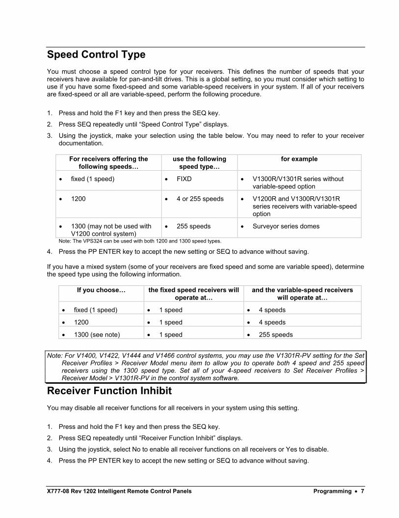
Speed Control Type You must choose a speed control type for your receivers. This defines the number of speeds that your receivers have available for pan-and-tilt drives. This is a global setting, so you must consider which setting to use if you have some fixed-speed and some variable-speed receivers in your system. If all of your receivers are fixed-speed or all are variable-speed, perform the following procedure.
1. Press and hold the F1 key and then press the SEQ key.
2. Press SEQ repeatedly until “Speed Control Type” displays.
3. Using the joystick, make your selection using the table below. You may need to refer to your receiver documentation.
For receivers offering the
following speeds… use the following
speed type… for example
• fixed (1 speed) • FIXD • V1300R/V1301R series without variable-speed option
• 1200 • 4 or 255 speeds • V1200R and V1300R/V1301R series receivers with variable-speed option
• 1300 (may not be used with V1200 control system)
• 255 speeds • Surveyor series domes
Note: The VPS324 can be used with both 1200 and 1300 speed types.
4. Press the PP ENTER key to accept the new setting or SEQ to advance without saving. If you have a mixed system (some of your receivers are fixed speed and some are variable speed), determine the speed type using the following information.
If you choose… the fixed speed receivers will operate at…
and the variable-speed receivers will operate at…
• fixed (1 speed) • 1 speed • 4 speeds
• 1200 • 1 speed • 4 speeds
• 1300 (see note) • 1 speed • 255 speeds
Note: For V1400, V1422, V1444 and V1466 control systems, you may use the V1301R-PV setting for the Set Receiver Profiles > Receiver Model menu item to allow you to operate both 4 speed and 255 speed receivers using the 1300 speed type. Set all of your 4-speed receivers to Set Receiver Profiles > Receiver Model > V1301R-PV in the control system software.
Receiver Function Inhibit You may disable all receiver functions for all receivers in your system using this setting.
1. Press and hold the F1 key and then press the SEQ key.
2. Press SEQ repeatedly until “Receiver Function Inhibit” displays.
3. Using the joystick, select No to enable all receiver functions on all receivers or Yes to disable.
4. Press the PP ENTER key to accept the new setting or SEQ to advance without saving.
8 • Programming X777-08 Rev 1202 Intelligent Remote Control Panels
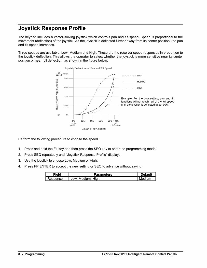
Joystick Response Profile The keypad includes a vector-solving joystick which controls pan and tilt speed. Speed is proportional to the movement (deflection) of the joystick. As the joystick is deflected further away from its center position, the pan and tilt speed increases. Three speeds are available: Low, Medium and High. These are the receiver speed responses in proportion to the joystick deflection. This allows the operator to select whether the joystick is more sensitive near its center position or near full deflection, as shown in the figure below.
Perform the following procedure to choose the speed.
1. Press and hold the F1 key and then press the SEQ key to enter the programming mode.
2. Press SEQ repeatedly until “Joystick Response Profile” displays.
3. Use the joystick to choose Low, Medium or High.
4. Press PP ENTER to accept the new setting or SEQ to advance without saving.
Field Parameters Default Response Low, Medium, High Medium
Example: For the Low setting, pan and tilt functions will not reach half of the full speed until the joystick is deflected about 90%.
X777-08 Rev 1202 Intelligent Remote Control Panels Programming • 9
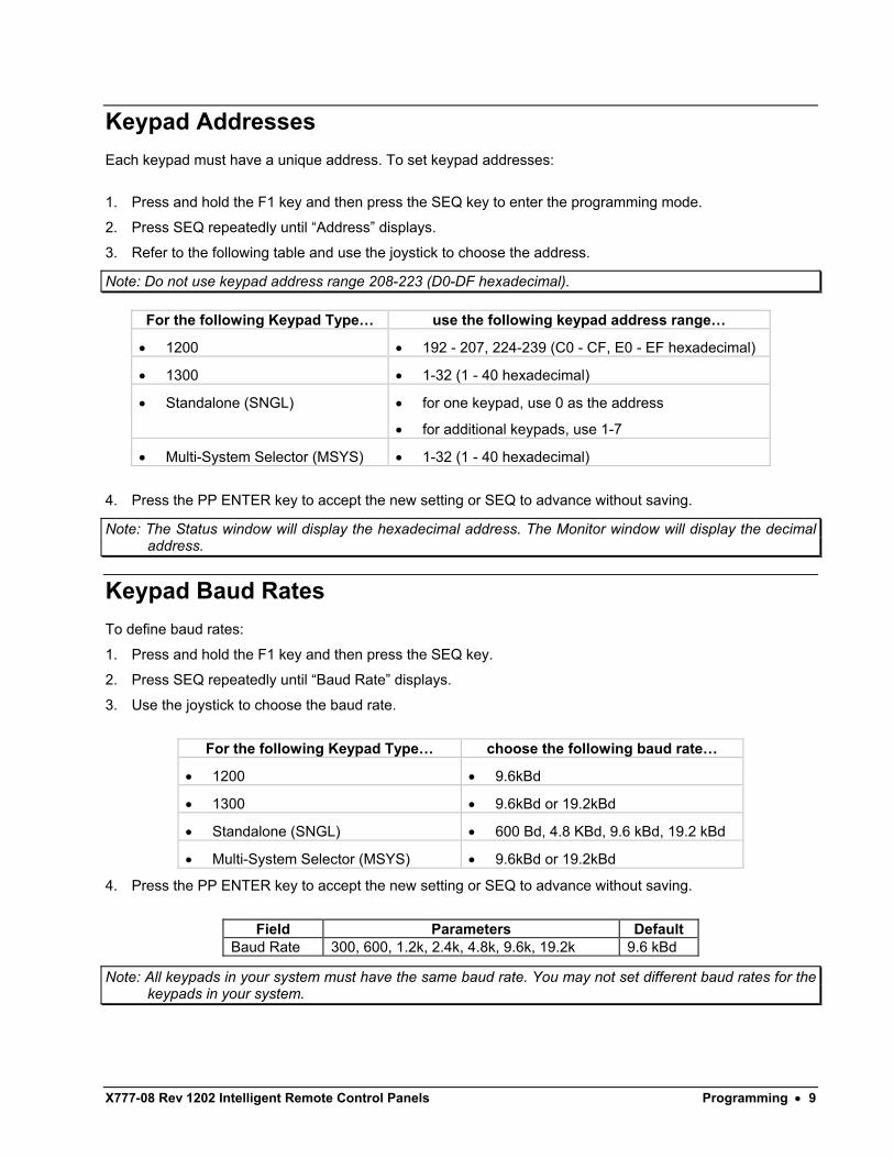
Keypad Addresses Each keypad must have a unique address. To set keypad addresses:
1. Press and hold the F1 key and then press the SEQ key to enter the programming mode.
2. Press SEQ repeatedly until “Address” displays.
3. Refer to the following table and use the joystick to choose the address.
Note: Do not use keypad address range 208-223 (D0-DF hexadecimal).
For the following Keypad Type… use the following keypad address range…
• 1200 • 192 - 207, 224-239 (C0 - CF, E0 - EF hexadecimal)
• 1300 • 1-32 (1 - 40 hexadecimal)
• Standalone (SNGL) • for one keypad, use 0 as the address
• for additional keypads, use 1-7
• Multi-System Selector (MSYS) • 1-32 (1 - 40 hexadecimal)
4. Press the PP ENTER key to accept the new setting or SEQ to advance without saving.
Note: The Status window will display the hexadecimal address. The Monitor window will display the decimal address.
Keypad Baud Rates To define baud rates:
1. Press and hold the F1 key and then press the SEQ key.
2. Press SEQ repeatedly until “Baud Rate” displays.
3. Use the joystick to choose the baud rate.
For the following Keypad Type… choose the following baud rate…
• 1200 • 9.6kBd
• 1300 • 9.6kBd or 19.2kBd
• Standalone (SNGL) • 600 Bd, 4.8 KBd, 9.6 kBd, 19.2 kBd
• Multi-System Selector (MSYS) • 9.6kBd or 19.2kBd
4. Press the PP ENTER key to accept the new setting or SEQ to advance without saving.
Field Parameters Default
Baud Rate 300, 600, 1.2k, 2.4k, 4.8k, 9.6k, 19.2k 9.6 kBd
Note: All keypads in your system must have the same baud rate. You may not set different baud rates for the keypads in your system.
10 • Programming X777-08 Rev 1202 Intelligent Remote Control Panels
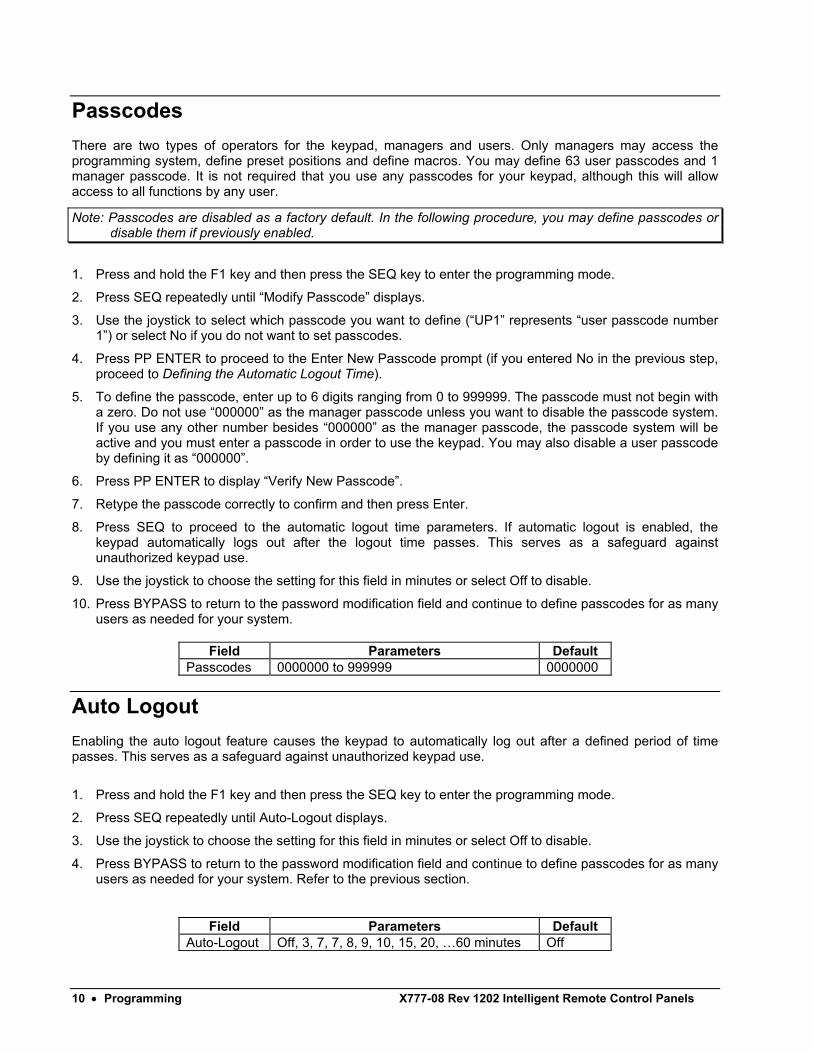
Passcodes There are two types of operators for the keypad, managers and users. Only managers may access the programming system, define preset positions and define macros. You may define 63 user passcodes and 1 manager passcode. It is not required that you use any passcodes for your keypad, although this will allow access to all functions by any user.
Note: Passcodes are disabled as a factory default. In the following procedure, you may define passcodes or disable them if previously enabled.
1. Press and hold the F1 key and then press the SEQ key to enter the programming mode.
2. Press SEQ repeatedly until “Modify Passcode” displays.
3. Use the joystick to select which passcode you want to define (“UP1” represents “user passcode number 1”) or select No if you do not want to set passcodes.
4. Press PP ENTER to proceed to the Enter New Passcode prompt (if you entered No in the previous step, proceed to Defining the Automatic Logout Time).
5. To define the passcode, enter up to 6 digits ranging from 0 to 999999. The passcode must not begin with a zero. Do not use “000000” as the manager passcode unless you want to disable the passcode system. If you use any other number besides “000000” as the manager passcode, the passcode system will be active and you must enter a passcode in order to use the keypad. You may also disable a user passcode by defining it as “000000”.
6. Press PP ENTER to display “Verify New Passcode”.
7. Retype the passcode correctly to confirm and then press Enter.
8. Press SEQ to proceed to the automatic logout time parameters. If automatic logout is enabled, the keypad automatically logs out after the logout time passes. This serves as a safeguard against unauthorized keypad use.
9. Use the joystick to choose the setting for this field in minutes or select Off to disable.
10. Press BYPASS to return to the password modification field and continue to define passcodes for as many users as needed for your system.
Field Parameters Default
Passcodes 0000000 to 999999 0000000
Auto Logout Enabling the auto logout feature causes the keypad to automatically log out after a defined period of time passes. This serves as a safeguard against unauthorized keypad use.
1. Press and hold the F1 key and then press the SEQ key to enter the programming mode.
2. Press SEQ repeatedly until Auto-Logout displays.
3. Use the joystick to choose the setting for this field in minutes or select Off to disable.
4. Press BYPASS to return to the password modification field and continue to define passcodes for as many users as needed for your system. Refer to the previous section.
Field Parameters Default Auto-Logout Off, 3, 7, 7, 8, 9, 10, 15, 20, …60 minutes Off
X777-08 Rev 1202 Intelligent Remote Control Panels Operation • 11
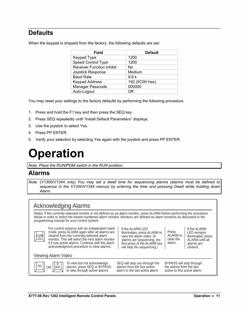
Defaults When the keypad is shipped from the factory, the following defaults are set:
Field Default Keypad Type 1200 Speed Control Type 1200 Receiver Function Inhibit No Joystick Response Medium Baud Rate 9.6 k Keypad Address 192 (0C0H hex) Manager Passcode 000000 Auto-Logout Off
You may reset your settings to the factory defaults by performing the following procedure.
1. Press and hold the F1 key and then press the SEQ key.
2. Press SEQ repeatedly until “Install Default Parameters” displays.
3. Use the joystick to select Yes.
4. Press PP ENTER.
5. Verify your selection by selecting Yes again with the joystick and press PP ENTER.
Operation Note: Place the RUN/PGM switch in the RUN position.
Alarms Note: (V1300/V1344 only) You may set a dwell time for sequencing alarms (alarms must be defined to
sequence in the V1300/V1344 menus) by entering the time and pressing Dwell while holding down Alarm.
Acknowledging Alarms
Viewing Alarm Video
For control systems with an independent stack mode, press ALARM again after all alarms are cleared from the currently-selected alarm monitor. This will select the next alarm monitor if it has active alarms. Continue with the alarm acknowledgment procedure to clear alarms.
To view but not acknowledge alarms, press SEQ or BYPASS to step through active alarms.
SEQ will step you through the alarms from the first active alarm to the last active alarm.
BYPASS will step through the alarms from the last active to first active alarm.
If the ALARM LED illuminates, press ALARM to view the alarm video. (If alarms are sequencing, the first press of the ALARM key will stop the sequencing.)
If the ALARM LED remains illuminated, press ALARM until all alarms are cleared.
Press ALARM to clear the alarm.
Notes: If the currently-selected monitor is not defined as an alarm monitor, press ALARM before performing the procedure below in order to select the lowest numbered alarm monitor. Monitors are defined as alarm monitors as discussed in the programming manual for your control system.
ALARM
PASSSEQBY
OR
12 • Operation X777-08 Rev 1202 Intelligent Remote Control Panels
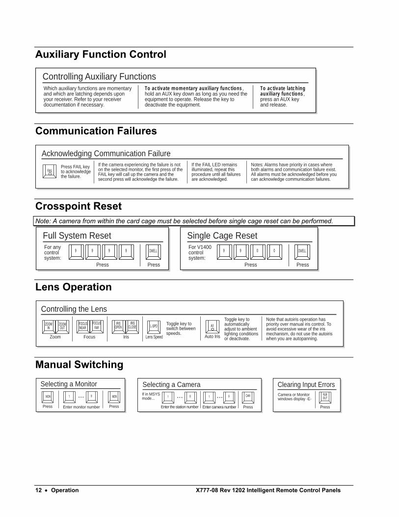
Auxiliary Function Control
Controlling Auxiliary FunctionsWhich auxiliary functions are momentary and which are latching depends upon your receiver. Refer to your receiver documentation if necessary.
To activate momentary auxiliary functions, hold an AUX key down as long as you need the equipment to operate. Release the key to deactivate the equipment. necessary.
To activate latching auxiliary functions, press an AUX key and release.
Communication Failures
Acknowledging Communication Failure
Press FAIL key to acknowledge the failure.
If the camera experiencing the failure is not on the selected monitor, the first press of the FAIL key will call up the camera and the second press will acknowledge the failure.
If the FAIL LED remains illuminated, repeat this procedure until all failures are acknowledged.
Notes: Alarms have priority in cases where both alarms and communication failure exist. All alarms must be acknowledged before you can acknowledge communication failures.
FAIL
Crosspoint Reset Note: A camera from within the card cage must be selected before single cage reset can be performed.
99 9 9
Full System Reset
Press Press
DWELLFor any control system:
09 9 0
Single Cage Reset
Press Press
DWELLFor V1400 control system:
Lens Operation
Controlling the Lens
Zoom Focus Iris Lens Speed
Toggle key to automatically adjust to ambient lighting conditions or deactivate.
Note that autoiris operation has priority over manual iris control. To avoid excessive wear of the iris mechanism, do not use the autoiris when you are autopanning.
OUTINZOOMZOOM
FARFOCUS
NEARFOCUS
CLOSEOPENIRISIRIS
L-SPD
Auto Iris
A/IToggle key to switch between speeds.
Manual Switching
9MON 1 ...
Selecting a Monitor
Press
MON
PressEnter monitor number
91 ...81 ...
Selecting a Camera
PressEnter camera number
If in MSYSmode...
CAM
Clearing Input Errors
Press
Camera or Monitorwindows display -E- OUT
RUB
Enter the station number
X777-08 Rev 1202 Intelligent Remote Control Panels Operation • 13
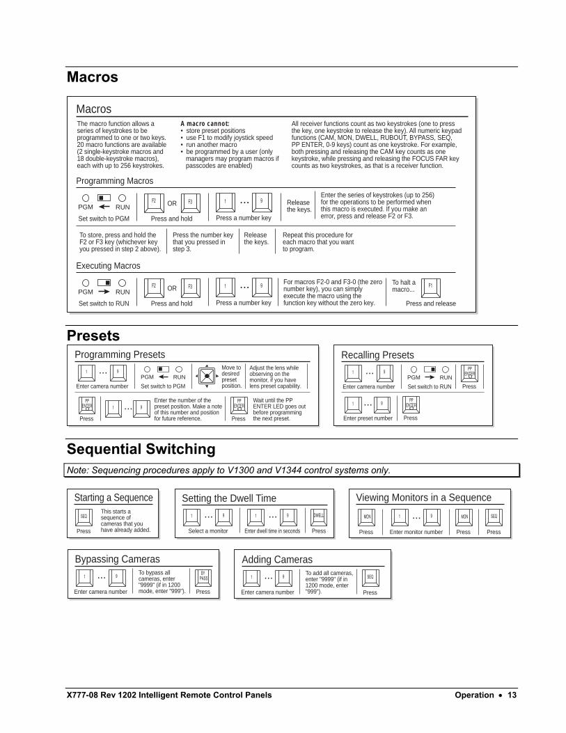
Macros
Programming Macros
Macros
Enter the series of keystrokes (up to 256) for the operations to be performed when this macro is executed. If you make an error, press and release F2 or F3.
To store, press and hold the F2 or F3 key (whichever key you pressed in step 2 above).
Press the number key that you pressed in step 3.
Release the keys.
Repeat this procedure for each macro that you want to program.
Release the keys.
The macro function allows a series of keystrokes to be programmed to one or two keys. 20 macro functions are available (2 single-keystroke macros and 18 double-keystroke macros), each with up to 256 keystrokes.
All receiver functions count as two keystrokes (one to press the key, one keystroke to release the key). All numeric keypad functions (CAM, MON, DWELL, RUBOUT, BYPASS, SEQ, PP ENTER, 0-9 keys) count as one keystroke. For example, both pressing and releasing the CAM key counts as one keystroke, while pressing and releasing the FOCUS FAR key counts as two keystrokes, as that is a receiver function.
A macro cannot:• store preset positions• use F1 to modify joystick speed• run another macro• be programmed by a user (only � managers may program macros if � passcodes are enabled)
OR
Set switch to PGM Press and hold
PGM RUNF2 F3 91 ...
Press a number key
Executing Macros
For macros F2-0 and F3-0 (the zero number key), you can simply execute the macro using the function key without the zero key.
To halt a macro...OR
Set switch to RUN Press and hold
PGM RUNF2
Press and release
F1F3 91 ...Press a number key
Presets
Set switch to PGM
91 ...
Programming Presets
Enter camera number
91 ...
Move to desired preset position.
Adjust the lens while observing on the monitor, if you have lens preset capability.
Enter the number of the preset position. Make a note of this number and position for future reference.
Wait until the PP ENTER LED goes out before programming the next preset.Press
PGM RUN
ENTERPP
Press
ENTERPP
Set switch to RUN
91 ...
Recalling Presets
Enter camera number
91 ...Enter preset number
Press
PGM RUNENTER
PP
Press
ENTERPP
Sequential Switching Note: Sequencing procedures apply to V1300 and V1344 control systems only.
9MON 1 ...
Viewing Monitors in a Sequence
Press
MON
Press PressEnter monitor number
SEQ91 ...
Setting the Dwell Time
PressSelect a monitor
91 ...
Enter dwell time in seconds
DWELL
91 ...
Bypassing Cameras
PressEnter camera number
To bypass all cameras, enter "9999" (if in 1200 mode, enter "999").
PASSBY
91 ...
Adding Cameras
Enter camera number
To add all cameras, enter "9999" (if in 1200 mode, enter "999"). Press
SEQ
Starting a Sequence
Press
SEQThis starts a sequence of cameras that you have already added.
14 • Operation X777-08 Rev 1202 Intelligent Remote Control Panels
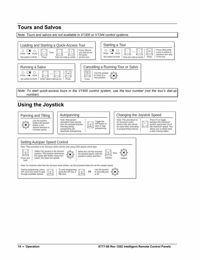
Tours and Salvos Note: Tours and salvos are not available in V1300 or V1344 control systems.
Set switch to RUN
91 ...
Starting a TourPress SEQ while a tour is active to advance one step in the tour.Press
SEQPGM RUN
Set switch to RUN
91 ...
Running a Salvo
Enter salvo's dial-up no. Press
CAMPGM RUN
Set switch to RUN
99 1 ...
Loading and Starting a Quick-Access Tour
Enter tour's dial-up number Enter tour's dial-up number
Press SEQ at any time to run the quick-access tour.Press
ThenPGM RUN
Cancelling a Running Tour or Salvo
Press
Use the joystick to move to a new position.
OUTRUB
Note: To start quick-access tours in the V1400 control system, use the tour number (not the tour’s dial-up number).
Using the Joystick
Setting Autopan Speed Control
Press andhold
Note: This procedure is for Surveyor series domes only using 1300 speed control type.
Note: For receivers other than the Surveyor series domes, use the procedure below the set the autopan speed.
Deflect the joystick to the desired position. This position determines the speed (the farther away from center, the faster the speed).
During autopanning, press A/P up to four times to step through available speeds.
When the unit has reached the desired speed, hold the joystick in place and then...
A/P
A/PTo stop autopanning, press the A/P key a fifth time.
Use the joystick to manually pan or tilt.
A/P
A/P
release release
then...
OR
Panning and TiltingUse the joystick. Deflect the joystick farther in the desired direction to increase speed.
AutopanningNote: Manual pan operations have priority over the autopan function. Panning during autopanning will deactivate autopanning.
Toggle the A/P button to start or stop autopanning.
A/P
Changing the Joystick SpeedNote: This procedure is for Surveyor series domes only and cannot be used when executing or programming macros.
Press F1 to toggle between the maximum joystick speed and 1/6 of the maximum speed. This allows you to easily track a slow moving object.
F1
X777-08 Rev 1202 Intelligent Remote Control Panels Diagnostics • 15
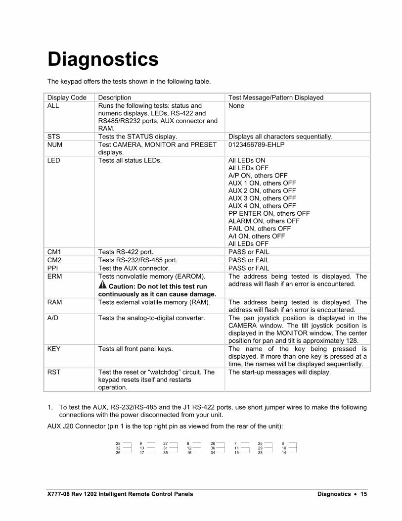
Diagnostics The keypad offers the tests shown in the following table. Display Code Description Test Message/Pattern Displayed ALL Runs the following tests: status and
numeric displays, LEDs, RS-422 and RS485/RS232 ports, AUX connector and RAM.
None
STS Tests the STATUS display. Displays all characters sequentially. NUM Test CAMERA, MONITOR and PRESET
displays. 0123456789-EHLP
LED Tests all status LEDs. All LEDs ON All LEDs OFF A/P ON, others OFF AUX 1 ON, others OFF AUX 2 ON, others OFF AUX 3 ON, others OFF AUX 4 ON, others OFF PP ENTER ON, others OFF ALARM ON, others OFF FAIL ON, others OFF A/I ON, others OFF All LEDs OFF
CM1 Tests RS-422 port. PASS or FAIL CM2 Tests RS-232/RS-485 port. PASS or FAIL PPI Test the AUX connector. PASS or FAIL ERM Tests nonvolatile memory (EAROM).
Caution: Do not let this test run continuously as it can cause damage.
The address being tested is displayed. The address will flash if an error is encountered.
RAM Tests external volatile memory (RAM). The address being tested is displayed. The address will flash if an error is encountered.
A/D Tests the analog-to-digital converter. The pan joystick position is displayed in the CAMERA window. The tilt joystick position is displayed in the MONITOR window. The center position for pan and tilt is approximately 128.
KEY Tests all front panel keys. The name of the key being pressed is displayed. If more than one key is pressed at a time, the names will be displayed sequentially.
RST Test the reset or “watchdog” circuit. The keypad resets itself and restarts operation.
The start-up messages will display.
1. To test the AUX, RS-232/RS-485 and the J1 RS-422 ports, use short jumper wires to make the following connections with the power disconnected from your unit.
AUX J20 Connector (pin 1 is the top right pin as viewed from the rear of the unit):
28 32 36
9 13 17
27 31 35
8 12 16
26 30 34
7 11 15
25 29 33
6 10 14
16 • Maintenance X777-08 Rev 1202 Intelligent Remote Control Panels
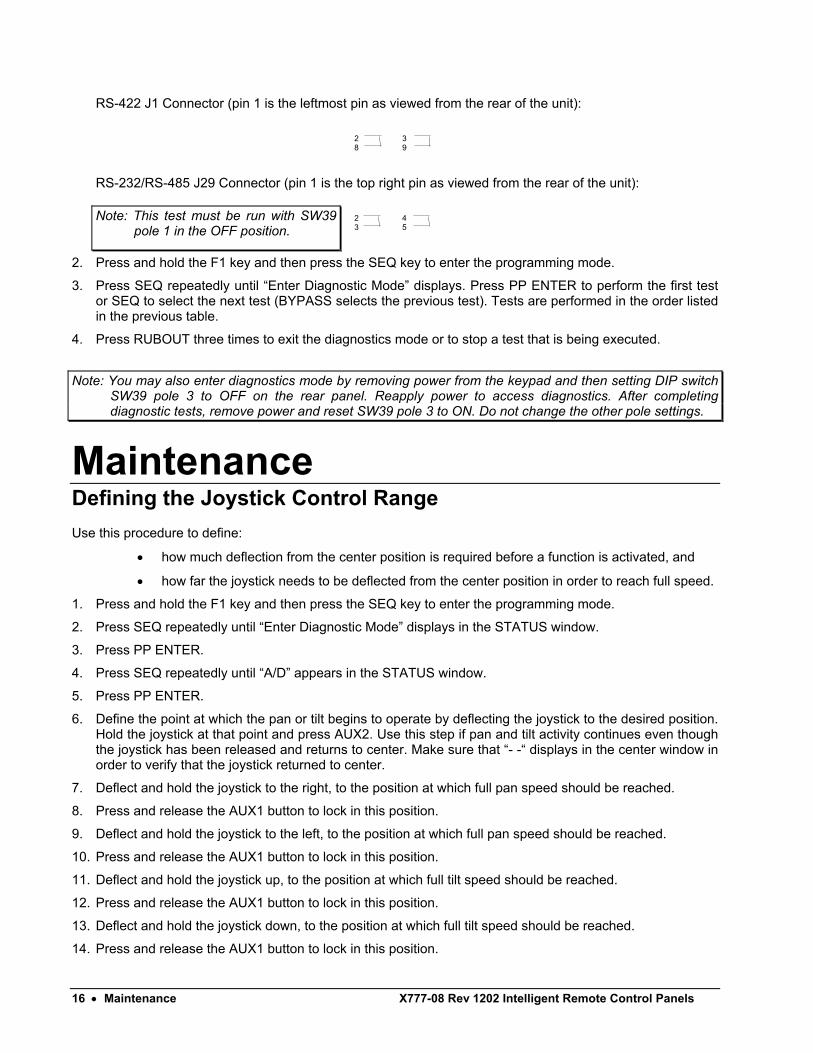
RS-422 J1 Connector (pin 1 is the leftmost pin as viewed from the rear of the unit):
2 8
3 9
RS-232/RS-485 J29 Connector (pin 1 is the top right pin as viewed from the rear of the unit):
2 3
4 5
2. Press and hold the F1 key and then press the SEQ key to enter the programming mode.
3. Press SEQ repeatedly until “Enter Diagnostic Mode” displays. Press PP ENTER to perform the first test or SEQ to select the next test (BYPASS selects the previous test). Tests are performed in the order listed in the previous table.
4. Press RUBOUT three times to exit the diagnostics mode or to stop a test that is being executed.
Note: You may also enter diagnostics mode by removing power from the keypad and then setting DIP switch SW39 pole 3 to OFF on the rear panel. Reapply power to access diagnostics. After completing diagnostic tests, remove power and reset SW39 pole 3 to ON. Do not change the other pole settings.
Maintenance Defining the Joystick Control Range Use this procedure to define:
• how much deflection from the center position is required before a function is activated, and
• how far the joystick needs to be deflected from the center position in order to reach full speed.
1. Press and hold the F1 key and then press the SEQ key to enter the programming mode.
2. Press SEQ repeatedly until “Enter Diagnostic Mode” displays in the STATUS window.
3. Press PP ENTER.
4. Press SEQ repeatedly until “A/D” appears in the STATUS window.
5. Press PP ENTER.
6. Define the point at which the pan or tilt begins to operate by deflecting the joystick to the desired position. Hold the joystick at that point and press AUX2. Use this step if pan and tilt activity continues even though the joystick has been released and returns to center. Make sure that “- -“ displays in the center window in order to verify that the joystick returned to center.
7. Deflect and hold the joystick to the right, to the position at which full pan speed should be reached.
8. Press and release the AUX1 button to lock in this position.
9. Deflect and hold the joystick to the left, to the position at which full pan speed should be reached.
10. Press and release the AUX1 button to lock in this position.
11. Deflect and hold the joystick up, to the position at which full tilt speed should be reached.
12. Press and release the AUX1 button to lock in this position.
13. Deflect and hold the joystick down, to the position at which full tilt speed should be reached.
14. Press and release the AUX1 button to lock in this position.
Note: This test must be run with SW39 pole 1 in the OFF position.
X777-08 Rev 1202 Intelligent Remote Control Panels Reference • 17
15. Verify proper setup by moving the joystick in each direction and monitor how far the joystick must move before the PRESET window reaches “69”. The number “69” indicates full speed while “- -“ indicates OFF. Use the “- -“ to verify correct dead zone setting. Make sure the “- -“ displays in the PRESET window when the joystick is released and returns to center.
16. Press the RUBOUT key three times to exit the A/D test.
17. Press SEQ until RST is displayed.
18. Press PP ENTER to exit the Diagnostic mode.
Fuse Replacement One fuse is located on the rear panel of the keypad. On the V1300X-DVC model, the fuse is rated at 2 A, 3AG. On the 120 VAC version of the V1300X-RVC, the fuse is rated at ½ A, 3AG. On the V1300X-RVC model with 230 VAC power, the fuse is ¼ A, 3AG. To replace the fuse, perform the following procedure.
1. Remove power from the unit.
2. Turn the fuse cap counterclockwise to release it from the unit.
3. Remove the fuse and replace it with an appropriate fuse as discussed in the paragraph above.
4. Replace the fuse cap.
Caution: Using a fuse with an incorrect rating can result in component damage and/or fire.
Reference Keypad Messages
Code Explanation ALSQ or AC:1 “All Cameras in Sequence” ALBY or AC:0 “All Cameras in Bypass” ALRM “ALARM” (unacknowledged alarms are indicated by a flashing ALARM LED,
acknowledged alarms are indicated by a steady LED). -E- “Error” (error on monitor or camera input) FAIL “Communication Failure” (unacknowledged failures are indicated by a flashing FAIL
LED, acknowledged but still active failures are indicated by a steady LED). I “In” (sequence) O “Out” (bypass) P1 “Priority 1 Alarm” (receiver or local alarm input activated). P2 “Priority 2 Alarm” (communication failure). P3 “Priority 3 Alarm” (alarm sequencing active). PE “Preset Entry Error” PROG “Program Mode” (the RUN/PGM switch is in the “program” position). PS “Program Set” (sequential data entry completed). PSTR “Preset Store” RECM “Record Macro” SE “Switcher Error” (cabling, protocol settings not matching, other transmission error). The
address of the switcher will be displayed in the CAMERA window. Applies to 1300 remote switcher when one of the remote V1344SCPU-HDRA's fail.
SP “Set Program” (for sequential data entry). SS:0 “Camera in Bypass” SS:1 “Camera in Sequence” SZE “Seize” (camera has been seized by a keypad with a higher priority).
18 • Technical Information X777-08 Rev 1202 Intelligent Remote Control Panels
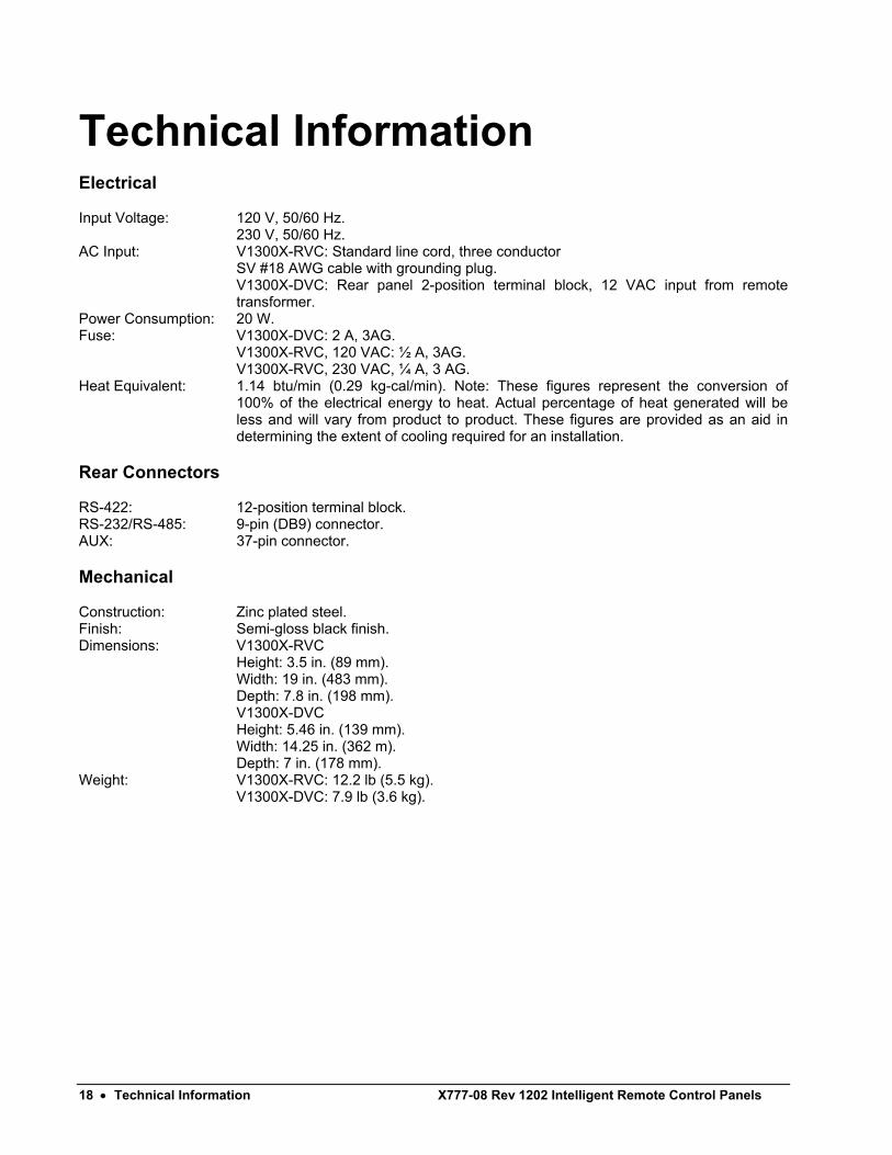
Technical Information Electrical Input Voltage: 120 V, 50/60 Hz. 230 V, 50/60 Hz. AC Input: V1300X-RVC: Standard line cord, three conductor
SV #18 AWG cable with grounding plug. V1300X-DVC: Rear panel 2-position terminal block, 12 VAC input from remote transformer.
Power Consumption: 20 W. Fuse: V1300X-DVC: 2 A, 3AG. V1300X-RVC, 120 VAC: ½ A, 3AG. V1300X-RVC, 230 VAC, ¼ A, 3 AG. Heat Equivalent: 1.14 btu/min (0.29 kg-cal/min). Note: These figures represent the conversion of
100% of the electrical energy to heat. Actual percentage of heat generated will be less and will vary from product to product. These figures are provided as an aid in determining the extent of cooling required for an installation.
Rear Connectors RS-422: 12-position terminal block. RS-232/RS-485: 9-pin (DB9) connector. AUX: 37-pin connector. Mechanical Construction: Zinc plated steel. Finish: Semi-gloss black finish. Dimensions: V1300X-RVC
Height: 3.5 in. (89 mm). Width: 19 in. (483 mm). Depth: 7.8 in. (198 mm).
V1300X-DVC Height: 5.46 in. (139 mm). Width: 14.25 in. (362 m). Depth: 7 in. (178 mm).
Weight: V1300X-RVC: 12.2 lb (5.5 kg). V1300X-DVC: 7.9 lb (3.6 kg).
X777-08 Rev 1202 Intelligent Remote Control Panels Shipping Instructions • 19
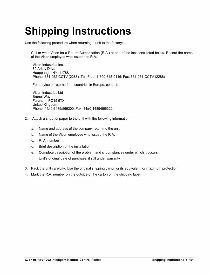
Shipping Instructions Use the following procedure when returning a unit to the factory:
1. Call or write Vicon for a Return Authorization (R.A.) at one of the locations listed below. Record the name of the Vicon employee who issued the R.A.
Vicon Industries Inc. 89 Arkay Drive Hauppauge, NY 11788 Phone: 631-952-CCTV (2288); Toll-Free: 1-800-645-9116; Fax: 631-951-CCTV (2288)
For service or returns from countries in Europe, contact:
Vicon Industries Ltd Brunel Way Fareham, PO15 5TX United Kingdom Phone: 44/(0)1489/566300; Fax: 44/(0)1489/566322
2. Attach a sheet of paper to the unit with the following information:
a. Name and address of the company returning the unit
b. Name of the Vicon employee who issued the R.A.
c. R. A. number
d. Brief description of the installation
e. Complete description of the problem and circumstances under which it occurs
f. Unit’s original date of purchase, if still under warranty
3. Pack the unit carefully. Use the original shipping carton or its equivalent for maximum protection.
4. Mark the R.A. number on the outside of the carton on the shipping label.
Vicon Industries Inc. Offices
Corporate Headquarters89 Arkay Drive
Hauppauge, New York 11788631-952-CCTV (2288) 800-645-9116
Fax: 631-951-CCTV (2288)✆Infofax: 800-287-1207
Vicon EuropeHeadquarters
Brunel WayFareham, PO15 5TX
United Kingdom+44 (0) 1489 566300
Fax: +44 (0) 1489 566322
Brussels OfficePlanet II - Unit E
Leuvensesteenweg 542B-1930 Zaventem
Belgium+32 (2) 712 8780
Fax: +32 (2) 712 8781
Far East OfficeUnit 5, 17/F, Metropole Square
8 On Yiu Street, ShatinNew Territories,
Hong Kong(852) 2145-7118
Fax: (852) 2145-7117
Internet Address: www.vicon-cctv.com