Embed Size (px)
Citation preview
INST
RUC
TIO
NA
L
2
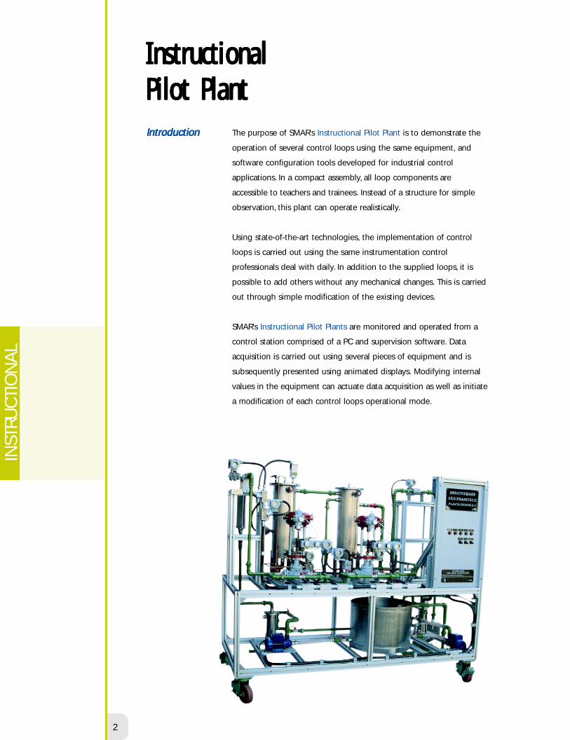
The purpose of SMAR's Instructional Pilot Plant is to demonstrate the
operation of several control loops using the same equipment, and
software configuration tools developed for industrial control
applications. In a compact assembly, all loop components are
accessible to teachers and trainees. Instead of a structure for simple
observation, this plant can operate realistically.
Using state-of-the-art technologies, the implementation of control
loops is carried out using the same instrumentation control
professionals deal with daily. In addition to the supplied loops, it is
possible to add others without any mechanical changes. This is carried
out through simple modification of the existing devices.
SMAR's Instructional Pilot Plants are monitored and operated from a
control station comprised of a PC and supervision software. Data
acquisition is carried out using several pieces of equipment and is
subsequently presented using animated displays. Modifying internal
values in the equipment can actuate data acquisition as well as initiate
a modification of each control loops operational mode.
InstructionalInstructionalInstructionalInstructionalInstructionalPPPPPilot Plantilot Plantilot Plantilot Plantilot PlantIntroductionIntroductionIntroductionIntroductionIntroduction

smar
3
GeneralGeneralGeneralGeneralGeneral
Characteristics ofCharacteristics ofCharacteristics ofCharacteristics ofCharacteristics of
the Pilot Plantsthe Pilot Plantsthe Pilot Plantsthe Pilot Plantsthe Pilot Plants
SMAR's Instruction Pilot Plants are easy to transport and include the following important features:
• Integral components requiring no assembly or disassembly.
• Light weight construction for easy movement.
All process tanks are constructed of stainless steel. Line pipes are of carbon steel, adequately
painted in order to prolong their service life.
All electrical and control equipment is clearly visible to trainees. The panel includes a controller
and graphic recorder installed side-by-side with switches, push - buttons and signal lamps. The
control board includes the plant's identification, as well as information about the user and the
main control strategies.
The AIMAX-Win supervision system includes software to monitor and actuate the control
systems while the plant is in operation. This also provides tools for the creation of displays,
graphic recording, handling of alarms, reports, and data banks. Information can be transfered to
other applications and be visualized on multiple monitors. The supervision station is not
physically connected to the plant allows remote operation.
There are three Fieldbus plant models available:
• PD2: Fieldbus Foundation Technology, including flowrate and level loops.
• PD3: Fieldbus Foundation Technology, including flowrate, temperature and level loops.
• PD4: Fieldbus Foundation Technology, grouping Plants II and III.
PILOT PLANTPILOT PLANTPILOT PLANTPILOT PLANTPILOT PLANT 4
INST
RUC
TIO
NA
L
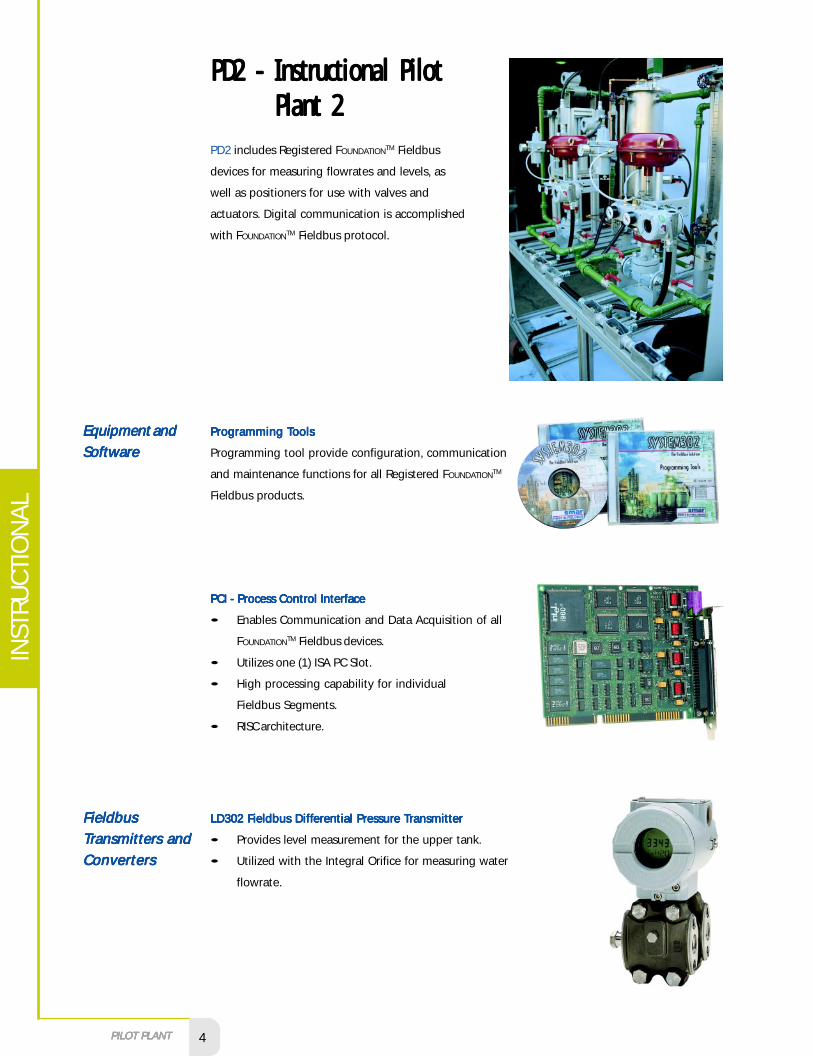
PD2 - Instructional PilotPD2 - Instructional PilotPD2 - Instructional PilotPD2 - Instructional PilotPD2 - Instructional PilotPlant 2Plant 2Plant 2Plant 2Plant 2
PD2 includes Registered FOUNDATIONTM Fieldbus
devices for measuring flowrates and levels, as
well as positioners for use with valves and
actuators. Digital communication is accomplished
with FOUNDATIONTM Fieldbus protocol.
Equipment andEquipment andEquipment andEquipment andEquipment and
SoftwareSoftwareSoftwareSoftwareSoftware
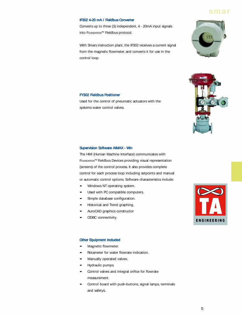
PPPPPrrrrrooooogrgrgrgrgramming amming amming amming amming TTTTToooooolsolsolsolsols
Programming tool provide configuration, communication
and maintenance functions for all Registered FOUNDATIONTM
Fieldbus products.
PCI - Process Control InterfacePCI - Process Control InterfacePCI - Process Control InterfacePCI - Process Control InterfacePCI - Process Control Interface
• Enables Communication and Data Acquisition of all
FOUNDATIONTM Fieldbus devices.
• Utilizes one (1) ISA PC Slot.
• High processing capability for individual
Fieldbus Segments.
• RISC architecture.
FieldbusFieldbusFieldbusFieldbusFieldbus
TTTTTrrrrransmittansmittansmittansmittansmitters anders anders anders anders and
ConvertersConvertersConvertersConvertersConverters
LD302 FLD302 FLD302 FLD302 FLD302 Fieldbus Dieldbus Dieldbus Dieldbus Dieldbus Diffiffiffiffifferererererenenenenential Ptial Ptial Ptial Ptial Prrrrressuressuressuressuressure e e e e TTTTTrrrrransmittansmittansmittansmittansmittererererer
• Provides level measurement for the upper tank.
• Utilized with the Integral Orifice for measuring water
flowrate.
smar
5
IF302 4-20 mA / Fieldbus ConverterIF302 4-20 mA / Fieldbus ConverterIF302 4-20 mA / Fieldbus ConverterIF302 4-20 mA / Fieldbus ConverterIF302 4-20 mA / Fieldbus Converter
Converts up to three (3) independent, 4 - 20mA input signals
into FOUNDATIONTM Fieldbus protocol.
With Smars instruction plant, the IF302 receives a current signal
from the magnetic flowmeter, and converts it for use in the
control loop.
FY302 Fieldbus PositionerFY302 Fieldbus PositionerFY302 Fieldbus PositionerFY302 Fieldbus PositionerFY302 Fieldbus Positioner
Used for the control of pneumatic actuators with the
systems water control valves.
Supervision Software AIMAX - WinSupervision Software AIMAX - WinSupervision Software AIMAX - WinSupervision Software AIMAX - WinSupervision Software AIMAX - Win
The HMI (Human Machine Interface) communicates with
FOUNDATIONTM Fieldbus Devices providing visual representation
(screens) of the control process. It also provides complete
control for each process loop including setpoints and manual
or automatic control options. Software characteristics include:
• Windows NT operating system.
• Used with PC compatible computers.
• Simple database configuration.
• Historical and Trend graphing.
• AutoCAD graphics constructor
• ODBC connectivity.
Other Equipment IncludedOther Equipment IncludedOther Equipment IncludedOther Equipment IncludedOther Equipment Included
• Magnetic flowmeter.
• Rotameter for water flowrate indication.
• Manually operated valves.
• Hydraulic pumps.
• Control valves and integral orifice for flowrate
measurement.
• Control board with push-buttons, signal lamps, terminals
and safetys.
PILOT PLANTPILOT PLANTPILOT PLANTPILOT PLANTPILOT PLANT 6
INST
RUC
TIO
NA
L
There are several strategies, easily implemented through simple modification of the configuration
software. Applications include two previously configured and tested strategies:
• Feedforward Control: level and outlet flowrate.
• Ratio Control.
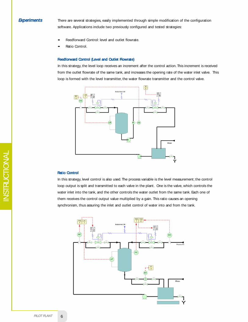
Feedforward Control (Level and Outlet Flowrate)Feedforward Control (Level and Outlet Flowrate)Feedforward Control (Level and Outlet Flowrate)Feedforward Control (Level and Outlet Flowrate)Feedforward Control (Level and Outlet Flowrate)
In this strategy, the level loop receives an increment after the control action. This increment is received
from the outlet flowrate of the same tank, and increases the opening rate of the water inlet valve. This
loop is formed with the level transmitter, the water flowrate transmitter and the control valve.
ExperimentsExperimentsExperimentsExperimentsExperiments
Ratio ControlRatio ControlRatio ControlRatio ControlRatio Control
In this strategy, level control is also used. The process variable is the level measurement; the control
loop output is split and transmitted to each valve in the plant. One is the valve, which controls the
water inlet into the tank, and the other controls the water outlet from the same tank. Each one of
them receives the control output value multiplied by a gain. This ratio causes an opening
synchronism, thus assuring the inlet and outlet control of water into and from the tank.
smar
7
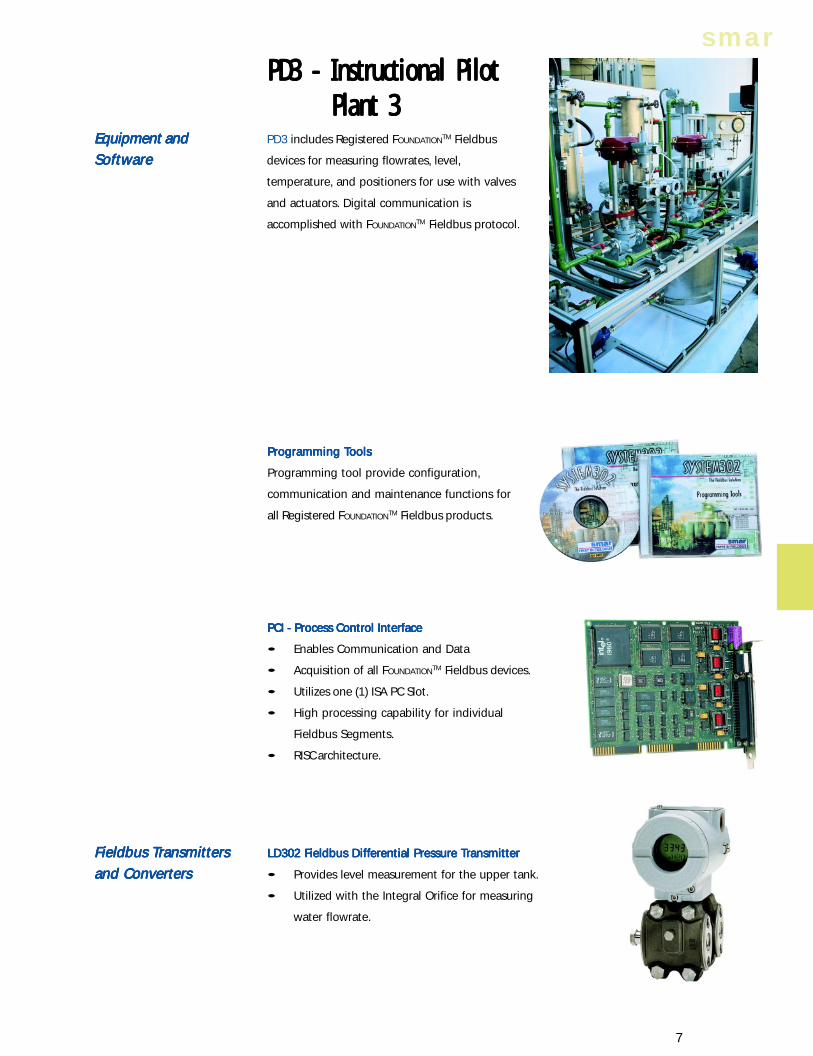
PD3 includes Registered FOUNDATIONTM Fieldbus
devices for measuring flowrates, level,
temperature, and positioners for use with valves
and actuators. Digital communication is
accomplished with FOUNDATIONTM Fieldbus protocol.
Equipment andEquipment andEquipment andEquipment andEquipment and
SoftwareSoftwareSoftwareSoftwareSoftware
PPPPPrrrrrooooogrgrgrgrgramming amming amming amming amming TTTTToooooolsolsolsolsols
Programming tool provide configuration,
communication and maintenance functions for
all Registered FOUNDATIONTM Fieldbus products.
PCI - Process Control InterfacePCI - Process Control InterfacePCI - Process Control InterfacePCI - Process Control InterfacePCI - Process Control Interface
• Enables Communication and Data
• Acquisition of all FOUNDATIONTM Fieldbus devices.
• Utilizes one (1) ISA PC Slot.
• High processing capability for individual
Fieldbus Segments.
• RISC architecture.
FFFFFieldbus ieldbus ieldbus ieldbus ieldbus TTTTTrrrrransmittansmittansmittansmittansmittersersersersers
and Convertersand Convertersand Convertersand Convertersand Converters
LD302 FLD302 FLD302 FLD302 FLD302 Fieldbus Dieldbus Dieldbus Dieldbus Dieldbus Diffiffiffiffifferererererenenenenential Ptial Ptial Ptial Ptial Prrrrressuressuressuressuressure e e e e TTTTTrrrrransmittansmittansmittansmittansmittererererer
• Provides level measurement for the upper tank.
• Utilized with the Integral Orifice for measuring
water flowrate.
PD3 - Instructional PilotPD3 - Instructional PilotPD3 - Instructional PilotPD3 - Instructional PilotPD3 - Instructional PilotPlant 3Plant 3Plant 3Plant 3Plant 3
PILOT PLANTPILOT PLANTPILOT PLANTPILOT PLANTPILOT PLANT 8
INST
RUC
TIO
NA
L
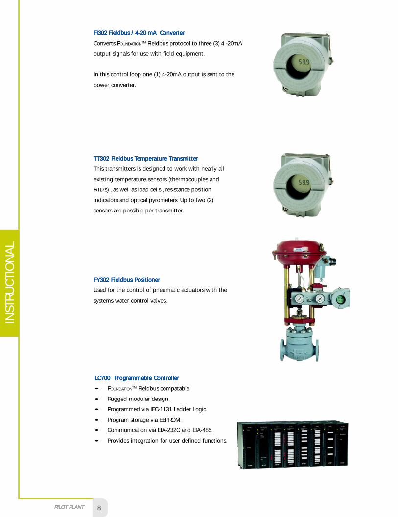
FI302 Fieldbus / 4-20 mA ConverterFI302 Fieldbus / 4-20 mA ConverterFI302 Fieldbus / 4-20 mA ConverterFI302 Fieldbus / 4-20 mA ConverterFI302 Fieldbus / 4-20 mA Converter
Converts FOUNDATIONTM Fieldbus protocol to three (3) 4 -20mA
output signals for use with field equipment.
In this control loop one (1) 4-20mA output is sent to the
power converter.
FY302 Fieldbus PositionerFY302 Fieldbus PositionerFY302 Fieldbus PositionerFY302 Fieldbus PositionerFY302 Fieldbus Positioner
Used for the control of pneumatic actuators with the
systems water control valves.
TTTTTT302 FT302 FT302 FT302 FT302 Fieldbus ieldbus ieldbus ieldbus ieldbus TTTTTempempempempemperererereraaaaaturturturturture e e e e TTTTTrrrrransmittansmittansmittansmittansmittererererer
This transmitters is designed to work with nearly all
existing temperature sensors (thermocouples and
RTD's) , as well as load cells , resistance position
indicators and optical pyrometers. Up to two (2)
sensors are possible per transmitter.
LC700 Programmable ControllerLC700 Programmable ControllerLC700 Programmable ControllerLC700 Programmable ControllerLC700 Programmable Controller
• FOUNDATIONTM Fieldbus compatable.
• Rugged modular design.
• Programmed via IEC-1131 Ladder Logic.
• Program storage via EEPROM.
• Communication via EIA-232C and EIA-485.
• Provides integration for user defined functions.
smar
9
CONF700 Configurator SoftwareCONF700 Configurator SoftwareCONF700 Configurator SoftwareCONF700 Configurator SoftwareCONF700 Configurator Software
• Windows 95/98 compatible.
• Programming via IEC-1131 Ladder Logic.
• Communication via EIA-232C and EIA-485.
• Provides integration for user defined functions.
Supervision Software - System302Supervision Software - System302Supervision Software - System302Supervision Software - System302Supervision Software - System302
The HMI (Human Machine Interface) communicates with
FOUNDATION Fieldbus Devices providing visual
representation (screens) of the control process. It also
provides complete control for each process loop including
setpoints and manual or automatic control options. Software
characteristics include:
• Windows NT operating system.
• Used with PC compatible computers.
• Simple database configuration.
• Historical and Trend graphing.
• AutoCAD graphics constructor.
• ODBC connectivity.
Other Equipment IncludedOther Equipment IncludedOther Equipment IncludedOther Equipment IncludedOther Equipment Included
• Power converter.
• Temperature sensor (RTD or thermocouple).
• Level switch.
• Conductive type temperature switch.
• Immersion resistor.
• Control valves.
• Integral orifice for flowrate measurement.
• Rotameter for water flowrate indication.
• Manually operated valves.
• Hydraulic pumps.
• Control panel with push-buttons, signal lamps,
terminals and protections.
PILOT PLANTPILOT PLANTPILOT PLANTPILOT PLANTPILOT PLANT 10
INST
RUC
TIO
NA
L
Several strategies may be implemented through simple modification of the configuration software.
The user will receive three previously configured strategies:
• Feedback Control: temperature.
• Cascade Control: temperature with cold water flowrate.
• Feed-forward Control in the heating tank : temperature with cold water flowrate.
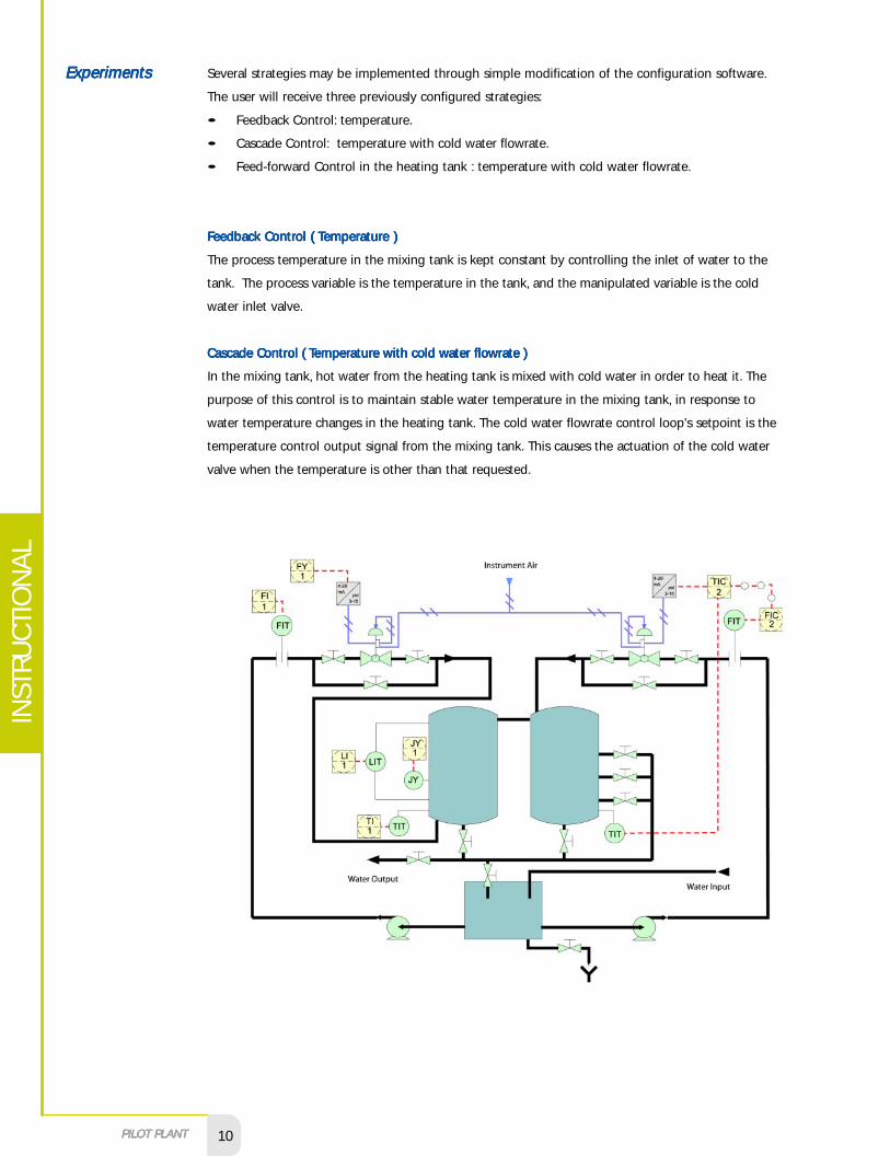
FFFFFeedback Ceedback Ceedback Ceedback Ceedback Cononononontrtrtrtrtrol ( ol ( ol ( ol ( ol ( TTTTTempempempempemperererereraaaaaturturturturture )e )e )e )e )
The process temperature in the mixing tank is kept constant by controlling the inlet of water to the
tank. The process variable is the temperature in the tank, and the manipulated variable is the cold
water inlet valve.
CCCCCascascascascascade Cade Cade Cade Cade Cononononontrtrtrtrtrol ( ol ( ol ( ol ( ol ( TTTTTempempempempemperererereraaaaaturturturturture with ce with ce with ce with ce with cold wold wold wold wold waaaaattttter floer floer floer floer flowrwrwrwrwraaaaattttte )e )e )e )e )
In the mixing tank, hot water from the heating tank is mixed with cold water in order to heat it. The
purpose of this control is to maintain stable water temperature in the mixing tank, in response to
water temperature changes in the heating tank. The cold water flowrate control loop's setpoint is the
temperature control output signal from the mixing tank. This causes the actuation of the cold water
valve when the temperature is other than that requested.
ExperimentsExperimentsExperimentsExperimentsExperiments
smar
11
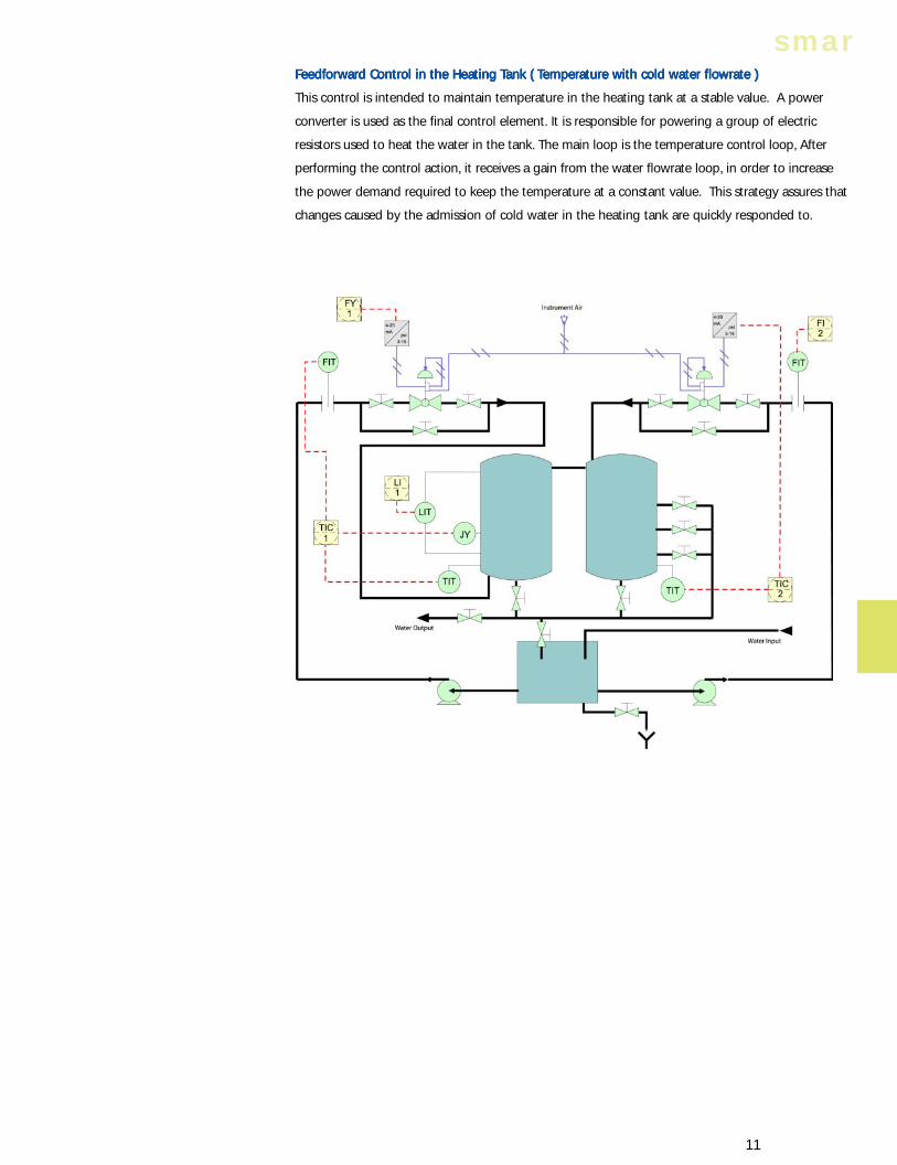
FFFFFeedfeedfeedfeedfeedforororororwwwwwararararard Cd Cd Cd Cd Cononononontrtrtrtrtrol in the Hol in the Hol in the Hol in the Hol in the Heaeaeaeaeating ting ting ting ting TTTTTank ank ank ank ank ( ( ( ( ( TTTTTempempempempemperererereraaaaaturturturturture with ce with ce with ce with ce with cold wold wold wold wold waaaaattttter floer floer floer floer flowrwrwrwrwraaaaattttte )e )e )e )e )
This control is intended to maintain temperature in the heating tank at a stable value. A power
converter is used as the final control element. It is responsible for powering a group of electric
resistors used to heat the water in the tank. The main loop is the temperature control loop, After
performing the control action, it receives a gain from the water flowrate loop, in order to increase
the power demand required to keep the temperature at a constant value. This strategy assures that
changes caused by the admission of cold water in the heating tank are quickly responded to.
PILOT PLANTPILOT PLANTPILOT PLANTPILOT PLANTPILOT PLANT 12
INST
RUC
TIO
NA
L
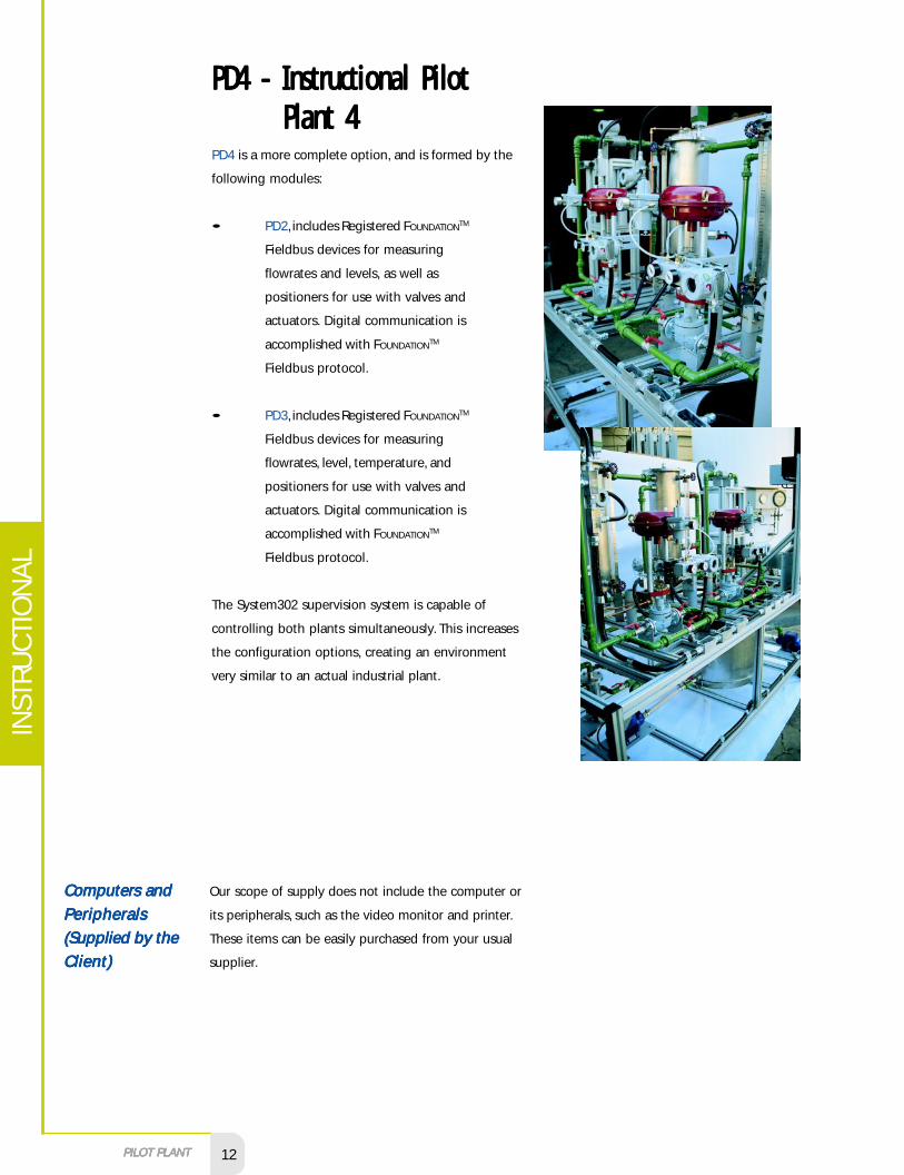
PD4 is a more complete option, and is formed by the
following modules:
• PD2, includes Registered FOUNDATIONTM
Fieldbus devices for measuring
flowrates and levels, as well as
positioners for use with valves and
actuators. Digital communication is
accomplished with FOUNDATIONTM
Fieldbus protocol.
• PD3, includes Registered FOUNDATIONTM
Fieldbus devices for measuring
flowrates, level, temperature, and
positioners for use with valves and
actuators. Digital communication is
accomplished with FOUNDATIONTM
Fieldbus protocol.
The System302 supervision system is capable of
controlling both plants simultaneously. This increases
the configuration options, creating an environment
very similar to an actual industrial plant.
Computers andComputers andComputers andComputers andComputers and
PeripheralsPeripheralsPeripheralsPeripheralsPeripherals
(Supplied by the(Supplied by the(Supplied by the(Supplied by the(Supplied by the
Client)Client)Client)Client)Client)
PD4 - Instructional PilotPD4 - Instructional PilotPD4 - Instructional PilotPD4 - Instructional PilotPD4 - Instructional PilotPlant 4Plant 4Plant 4Plant 4Plant 4
Our scope of supply does not include the computer or
its peripherals, such as the video monitor and printer.
These items can be easily purchased from your usual
supplier.
smar
13
The fastest microprocessors and highest RAM will provide the best
system performance. Smar's minimum recommendations are as follows:
• Operating System: Windows NT and Windows 95/98 ( Dual Boot );
• CD - ROM
• 1 spare ISA slot;
• 1 unused COM port.
• INTEL PENTIUM Microprocessors (minimum);
• 64 MB RAM (minimum);
• Hard - disk capacity greater than 500MB;
• SVGA Video Monitor of 17" (minimum).
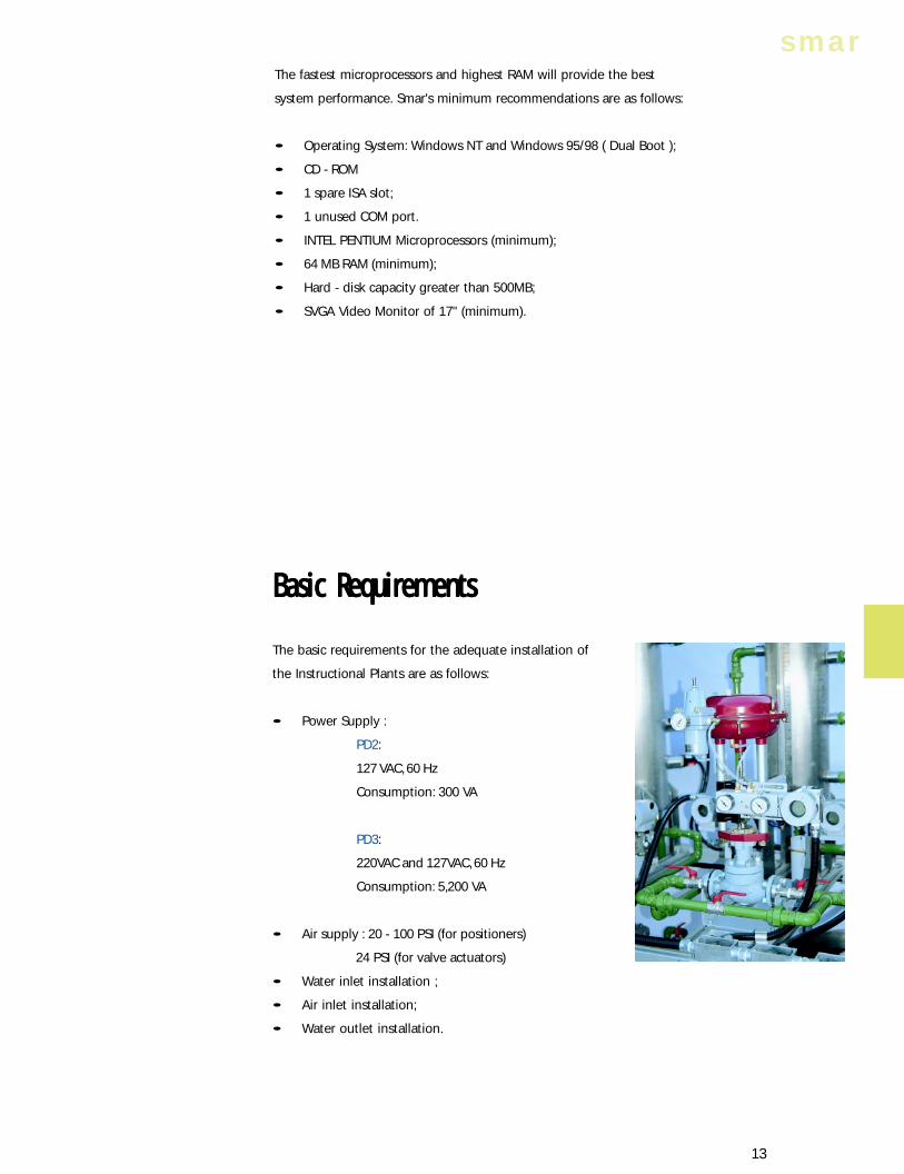
Basic RequirementsBasic RequirementsBasic RequirementsBasic RequirementsBasic Requirements
The basic requirements for the adequate installation of
the Instructional Plants are as follows:
• Power Supply :
PD2:
127 VAC, 60 Hz
Consumption: 300 VA
PD3:
220VAC and 127VAC, 60 Hz
Consumption: 5,200 VA
• Air supply : 20 - 100 PSI (for positioners)
24 PSI (for valve actuators)
• Water inlet installation ;
• Air inlet installation;
• Water outlet installation.

Assistance toAssistance toAssistance toAssistance toAssistance to
Start-upStart-upStart-upStart-upStart-up
TTTTTrrrrrainingainingainingainingaining
Smar may provide the following installation check-out and start-up services:
• Conformity check-out of the installations and Instructional Plant.
• Pre - operational tests.
• All required adjustments.
• Technical instructions.
• Clearing - out for operation.
Smar's Training Department offers specialized courses covering all aspects, from design to
maintenance, to fulfill the requirements of your technical staff. These courses may be carried out at the
Client's facilities or at our Training Centers worldwide.
Software and hardware configuration manuals, as well as installation and maintenance manuals are
supplied with the Plants. This coupled with courses offered by Smar, grant autonomy and make the
instructors fully capable of developing changes and modifications to the systems.
www.smar.com
INST
RUC
TIO
NA
L