Embed Size (px)
Citation preview

May 6, 2019
© S&C Electric Company 1949-2019, all rights reserved Instruction Sheet 212-505
S&C Power Fuses—Type SMD-2BOutdoor Distribution (115 kV and 138 kV)
Mountings and Fuse Units
Instructions for Field Assembly, Installation, and Maintenance
Table of Contents
Section Page Section Page
IntroductionQualified Persons . . . . . . . . . . . . . . . . . . . . . . . . . . . 2Read this Instruction Sheet . . . . . . . . . . . . . . . . . . . 2Retain this Instruction Sheet . . . . . . . . . . . . . . . . . . . 2Proper Application . . . . . . . . . . . . . . . . . . . . . . . . . . 2Warranty . . . . . . . . . . . . . . . . . . . . . . . . . . . . . . . . . . 2
Safety InformationUnderstanding Safety-Alert Messages . . . . . . . . . . . 3Following Safety Instructions . . . . . . . . . . . . . . . . . . 3Replacement Instructions and Labels . . . . . . . . . . . 3
Safety Precautions . . . . . . . . . . . . . . . . . . . . . . . . . 4
Assembling & Installing Fuse Unit into Mountings . . . . . . . . . . . . . . . . . . . . . . . . . . . . . . . . . 5
Adjustments . . . . . . . . . . . . . . . . . . . . . . . . . . . . . . 12
Attaching Fuse-Unit End Fittings . . . . . . . . . . . 13
Installing and Removing Fuse Units . . . . . . . . . 15
Opening and Closing Fuse-Unit Assemblies . . . . . . . . . . . . . . . . . . . . . . . . . . . . . . . 16
Replacing Blown Fuse Units . . . . . . . . . . . . . . . . 17
MaintenanceFuse-Unit Tube Refinishing . . . . . . . . . . . . . . . . . . .18Fuse-Unit Bore Inspection . . . . . . . . . . . . . . . . . . . .18
2 S&C Instruction Sheet 212-505
Introduction
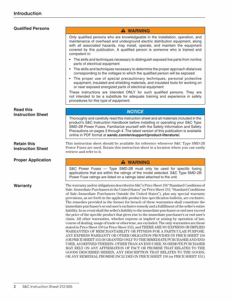
Qualified Persons WARNINGOnly qualified persons who are knowledgeable in the installation, operation, and maintenance of overhead and underground electric distribution equipment, along with all associated hazards, may install, operate, and maintain the equipment covered by this publication . A qualified person is someone who is trained and competent in:
• The skills and techniques necessary to distinguish exposed live parts from nonlive parts of electrical equipment
• The skills and techniques necessary to determine the proper approach distances corresponding to the voltages to which the qualified person will be exposed
• The proper use of special precautionary techniques, personal protective equipment, insulated and shielding materials, and insulated tools for working on or near exposed energized parts of electrical equipment
These instructions are intended ONLY for such qualified persons . They are not intended to be a substitute for adequate training and experience in safety procedures for this type of equipment .
Read this Instruction Sheet
NOTICEThoroughly and carefully read this instruction sheet and all materials included in the product’s S&C Instruction Handbook before installing or operating your S&C Type SMD-2B Power Fuses . Familiarize yourself with the Safety Information and Safety Precautions on pages 3 through 4 . The latest version of this publication is available online in PDF format at sandc.com/en/support/product-literature/.
Retain this Instruction Sheet
This instruction sheet should be available for reference whenever S&C Type SMD-2B Power Fuses are used. Retain this instruction sheet in a location where you can easily retrieve and refer to it.
Proper Application WARNINGS&C Power Fuses — Type SMD-2B must only be used for specific fusing applications that are within the ratings of the model selected . S&C Type SMD-2B Power Fuse ratings are listed on a ratings label attached to the unit .
Warranty The warranty and/or obligations described in S&C’s Price Sheet 150 “Standard Conditions of Sale–Immediate Purchasers in the United States” (or Price Sheet 153, “Standard Conditions of Sale–Immediate Purchasers Outside the United States”), plus any special warranty provisions, as set forth in the applicable product-line specification bulletin, are exclusive. The remedies provided in the former for breach of these warranties shall constitute the immediate purchaser’s or end user’s exclusive remedy and a fulfillment of the seller’s entire liability. In no event shall the seller’s liability to the immediate purchaser or end user exceed the price of the specific product that gives rise to the immediate purchaser’s or end user’s claim. All other warranties, whether express or implied or arising by operation of law, course of dealing, usage of trade or otherwise, are excluded. The only warranties are those stated in Price Sheet 150 (or Price Sheet 153), and THERE ARE NO EXPRESS OR IMPLIED WARRANTIES OF MERCHANTABILITY OR FITNESS FOR A PARTICULAR PURPOSE. ANY EXPRESS WARRANTY OR OTHER OBLIGATION PROVIDED IN PRICE SHEET 150 (OR PRICE SHEET 153) IS GRANTED ONLY TO THE IMMEDIATE PURCHASER AND END USER, AS DEFINED THEREIN. OTHER THAN AN END USER, NO REMOTE PURCHASER MAY RELY ON ANY AFFIRMATION OF FACT OR PROMISE THAT RELATES TO THE GOODS DESCRIBED HEREIN, ANY DESCRIPTION THAT RELATES TO THE GOODS, OR ANY REMEDIAL PROMISE INCLUDED IN PRICE SHEET 150 (or PRICE SHEET 153.)

Safety Information
S&C Instruction Sheet 212-505 3
Understanding Safety-Alert Messages
Several types of safety-alert messages may appear throughout this instruction sheet and on labels and tags attached to your S&C Type SMD-2B Power Fuses. Familiarize yourself with these types of messages and the importance of these various signal words:
DANGER“DANGER” identifies the most serious and immediate hazards that will likely result in serious personal injury or death if instructions, including recommended precautions, are not followed .
WARNING“WARNING” identifies hazards or unsafe practices that can result in serious personal injury or death if instructions, including recommended precautions, are not followed .
CAUTION“CAUTION” identifies hazards or unsafe practices that can result in minor personal injury if instructions, including recommended precautions, are not followed .
NOTICE“NOTICE” identifies important procedures or requirements that can result in product or property damage if instructions are not followed .
Following Safety Instructions
If you do not understand any portion of this instruction sheet and need assistance, contact your nearest S&C Sales Office or S&C Authorized Distributor. Their telephone numbers are listed on S&C’s website sandc.com, or call the S&C Global Monitoring and Support Center at 1-888-762-1100.
NOTICE
Read this instruction sheet thoroughly and carefully before installing your S&C Type SMD-2B Power Fuses .
Replacement Instructions and Labels
If you need additional copies of this instruction sheet, contact your nearest S&C Sales Office, S&C Authorized Distributor, S&C Headquarters, or S&C Electric Canada Ltd.
It is important that any missing, damaged, or faded labels on the equipment be replaced immediately. Replacement labels are available by contacting your nearest S&C Sales Office, S&C Authorized Distributor, S&C Headquarters, or S&C Electric Canada Ltd.
Safety Precautions
4 S&C Instruction Sheet 768-520
DANGERS&C Type SMD-2B Power Fuses operate at high voltage. Failure to observe the precautions below will result in serious personal injury or death.
Some of these precautions may differ from company operating procedures and rules . Where a discrepancy exists, users should follow their company’s operating procedures and rules .
1 . QUALIFIED PERSONS. Access to S&C Power Fuses: Types SMD-2B, must be restricted only to qualified persons . See the “Qualified Persons” section on page 2 .
2 . SAFETY PROCEDURES. Always follow safe operating procedures and rules .
3 . PERSONAL PROTECTIVE EQUIPMENT. Always use suitable protective equipment, such as rubber gloves, rubber mats, hard hats, safety glasses, arc-flash clothing, and fall-protection, in accordance with safe operating procedures and rules .
4 . SAFETY LABELS. Do not remove or obscure any of the “DANGER,” “WARNING,” “CAUTION,” or “NOTICE” labels and tags . Remove tags ONLY if instructed to do so .
5 . ENERGIZED COMPONENTS. Always consider all parts live until de-energized, tested, and grounded .
6 . MAINTAINING PROPER CLEARANCE. Always maintain proper clearance from energized components .
7 . Do not leave fuse units installed in the fuse mounting hanging open. When closed in, the fuse units will not be damaged by rain or high humidity . However, the watertightness of the exhaust end of the fuse units cannot be guaranteed; therefore, as a precaution, fuse units should not be left hanging open . Any rain or snow that might enter could affect the solid-materials lining . Moreover, when in storage, these fuse units should be protected from excessive moisture .
8 . Do not remove the fuse unit from its carton until ready to use.
9 . Handle fuse units with care. Do not drop or throw them .
10 . Do not place hand over the upper seal of the fuse unit when handling. There is the remote possibility the current-responsive section of the fuse unit may have been weakened in shipping or handling . As a result, the spring-loaded actuating pin may be unpredictably released and driven forcibly through the upper seal .
S&C Instruction Sheet 212-505 5
Assembling and Installing Fuse Unit into Mountings
These instructions apply to all mounting styles except where otherwise noted and are based on the use of standard station post insulators.
Follow these steps to assemble and install mountings. Repeat Steps 1 through 8 for each fuse mounting.
STEP 1. Leaving the mounting bases attached to the skid, carefully remove the outer crate. Inspect for any obvious shipping damage before continuing.
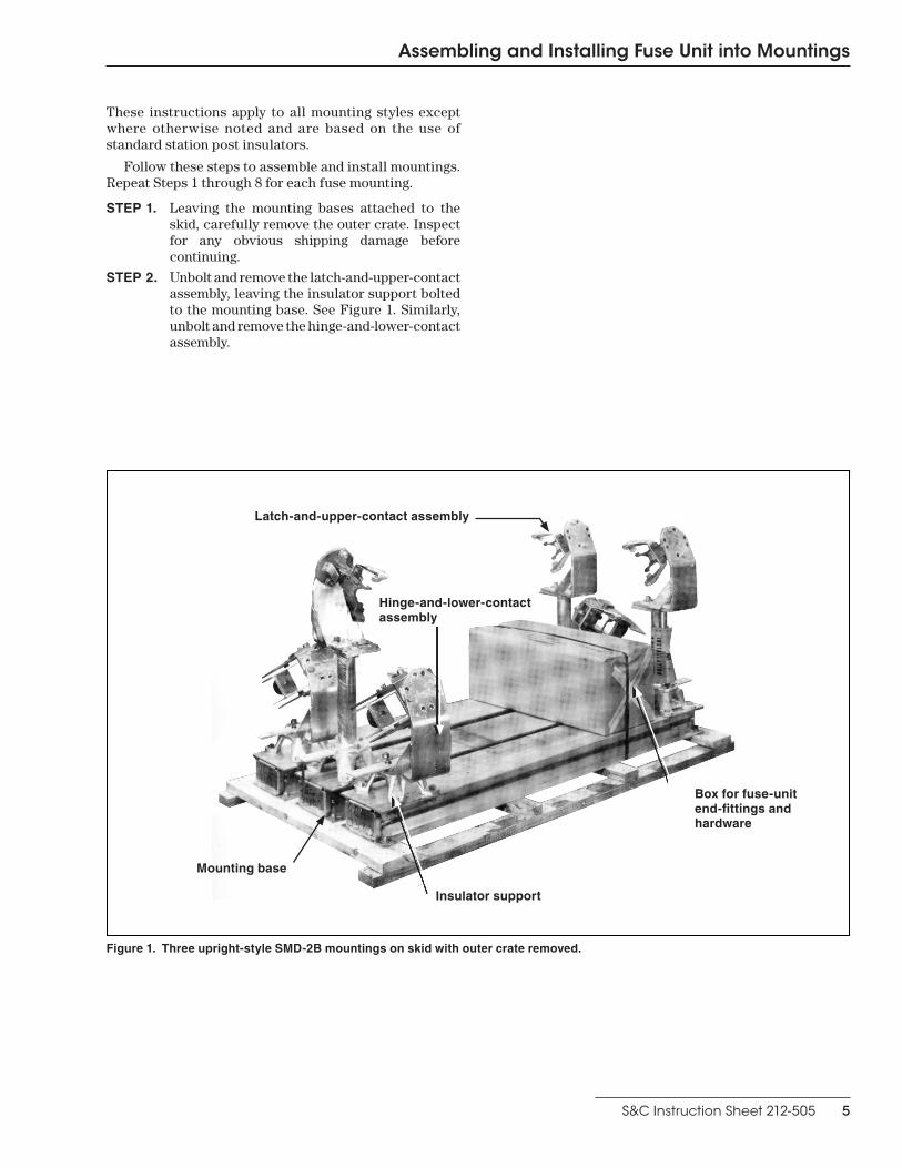
STEP 2. Unbolt and remove the latch-and-upper-contact assembly, leaving the insulator support bolted to the mounting base. See Figure 1. Similarly, unbolt and remove the hinge-and-lower-contact assembly.
Figure 1. Three upright-style SMD-2B mountings on skid with outer crate removed.
Box for fuse-unit end-fittings and hardware
Latch-and-upper-contact assembly
Mounting base
Insulator support
Hinge-and-lower-contact assembly

6 S&C Instruction Sheet 212-505
Assembling and Installing Fuse Unit into Mountings
Vertical, Inverted, and Upright Style Mountings: Assemble each insulator stack directly on its respective insulator support, using four 5/8—11×11/4-inch galvanized bolts and lock washers with each insulator stack. Before fully tightening the mounting bolts, adjust the insulator stacks to attain the spacing indicated in Figure 2. To compensate for minor variations in the insulators, it may be necessary to rotate
Figure 2. Spacing of insulator stacks and mounting arrangements of latch-and-upper-contact assembly and hinge-and-lower-contact assembly. See Figure 3 on page 7 for assembly of pedestal-style mounting.
Latch-and-Upper-Contact AssemblyHinge-and-Lower-Contact Assembly
Vertical Style, 180o Opening
Inverted Style (with inverted insulators)
Upright Style (When assembled as shown, the
fuse opens counterclockwise . All parts are symmetrical so the mounting may be assembled, if desired, for clockwise opening .)
Note: (Applicable to upright and pedestal styles) The bracket
weldments must be rotated about 71/2 degrees clockwise (for a
counterclockwise-opening fuse) . Place a straightedge (such as a hookstick) along line "A-A ."
Bracket weldments are properly aligned when both lie flat against
the straightedge .
Vertical Style, 45o Opening
111 Kv—59¾ inches (152 cm)±⅛-inch (3 mm)138 Kv—67¾ inches (172 cm)±⅛-inch (3 mm)
Center-to-center spacing of insulator racks
one or both insulator stacks either 90 degrees or 180 degrees to attain the specified center-to-center dimensions. Then, check to be sure the insulator stacks are plumb with respect to the mounting base. Shim the insulator stacks if necessary. Fully tighten the mounting bolts. Recheck to make sure the spacing indicated in Figure 2 was not lost in tightening the mounting bolts.

S&C Instruction Sheet 212-505 7
Assembling and Installing Fuse Unit into Mountings
CAUTIONFor inverted style mountings, the “dish” of the insulator skirts must face away from the mounting base .
Pedestal-Style Mountings: Attach insula-tor stacks to the base as described in Figure 3, using four 5/8—11×11/2-inch galvanized bolts and lock washers with each insulator stack. Fully tighten the mounting bolts.
Attach a mounting bracket to each insulator stack as shown in Figure 3, using four 5/8-inch—11×11/2-inch galvanized bolts and lock washers.
Note: Mounting brackets must be installed with the long leg attached to the insulator. Fully tighten the mounting bolts.
Measure the distance, shown in Figure 3, between the geometric centers of the hole pat-tern on the top surface of the mounting brackets. Also, lay a straight-edge across the tops of the brackets and note whether it rests flat on each surface. If adjustment is necessary, shim and/or rotate the insulator stacks either 90 degrees or
Figure 3. Assembly of mounting, pedestal style.
● Distance to be maintained between the geometric centers of the mounting bolt slot patterns on the top side of mounting brackets.
Mounting brackets
5/8—11×11/2-inch boltLock washer
Latch-and-upper-contact assembly
Hinge-and-lower-contact assembly
Lock washer
Skirt direction
5/8—11×11/2-inch bolt
Lock washer
Flat washer Flat washer
Base
Nut Nut
5/8—11×2-inch bolt
5/8—11×21/4-inch bolt
Lock washer
115 kV—59¾ inches (152 cm)±⅛-inch (3 mm)●67¾-inches (172 cm) ±⅛-inch (3 mm)●
180 degrees as required to attain the specified dimension and to align the top surfaces of the mounting brackets.
Vertical- and Inverted-Style Mountings: Mount the latch-and-upper-contact assembly on one insulator stack using two 5/8—11×11/2-inch galvanized bolts, lock washers, and flat wash-ers—placing the flat washers next to the slotted holes in the latch-and-upper-contact assembly. Do not fully tighten these mounting bolts at this time. See Figure 2 on page 6.
Upright-Style Mountings: Mount the latch-and-upper-contact assembly on one insulator stack using two 5/8—11×11/4-inch galvanized bolts and lock washers. Do not fully tighten these mounting bolts at this time. See Figure 2 on page 6.
Pedestal-Style Mountings: Attach the latch-and-upper-contact assembly to one mount-ing bracket, as illustrated in Figure 3, using two 5/8—11×2-inch galvanized bolts, flat washers, lock washers, and nuts—placing the flat washers on the underside of the mounting bracket next to the slotted holes. Do not fully tighten these mounting bolts at this time.

8 S&C Instruction Sheet 212-505
Assembling and Installing Fuse Unit into Mountings
STEP 3. Vertical- and Inverted-Style Mountings: Mount the hinge-and-lower-contact assembly on the other insulator stack using two 5/8—11×2-inch galvanized bolts and lock washers. Do not fully tighten these mounting bolts at this time. See Figure 2 on page 6.
Upright-Style Mountings: Mount the hinge-and-lower-contact assembly on the other insula-tor stack using two 5/8—11×11/2-inch galvanized bolts, lock washers, and flat washers—placing the flat washers next to the slotted holes in the hinge-and-lower-contact assembly. See Figure 2 on page 6. Do not fully tighten these mounting bolts at this time.
Pedestal-Style Mountings: Mount the hinge-and-lower-contact assembly on the other mounting bracket, as illustrated in Figure 3 on page 7, using two 5/8—11×21/4-inch galvanized bolts, flat washers, lock washers, and nuts—placing the flat washers on the underside of the mounting bracket next to the slotted holes. Do not fully tighten the mounting bolts at this time.
STEP 4. Step 6 does not apply to Vertical and Inverted Style Mountings:
Upright and Pedestal Style Mountings: Hold a straightedge (such as a hookstick) against the bracket weldments, as indicated by the line “A-A” in Figure 2 on page 6. Adjust either the latch-and-upper-contact assembly or the hinge-and-lower-contact assembly as required until the straightedge lies flat against both bracket weldments. Then, fully tighten all mounting bolts to secure the hinge-and-lower-contact assembly as well as the latch-and-upper-contact assembly. Recheck using the straightedge to be sure that the adjustment was not lost in tighten-ing the mounting bolts. As a point of informa-tion, the bracket weldments will not be square with the mounting base. Insert the rubber plug (furnished) in the exposed threaded hole in the insulator cap (upright style mountings only).
STEP 5. Unbolt the skid, hoist the fuse mounting, and bolt it into position on the supporting structure. Do not hoist the fuse mounting by rigging on the live parts. If necessary, shim the mounting base to eliminate any distortion caused by irregularities in the supporting structure.

S&C Instruction Sheet 212-505 9
Assembling and Installing Fuse Unit into Mountings
STEP 6. Make electrical connections.
DANGER
Do not energize the fuse mountings at this time .
If aluminum-alloy body connectors● are used, the following procedures should be used:
(a) Thoroughly wire-brush the current-transfer surfaces of each connector and immediately apply a liberal coating of Penetrox® A (available from Burndy Corporation) to the brushed surfaces.
(b) Apply a coating of Penetrox A to the terminal-pad surfaces, and then bolt the connectors to the terminal pads.
(c) Prepare the conductors using established procedures and clamp them in their respective connectors.
If rigid bus is used, slotted holes must be provided at the point of attachment to the terminal pads at the latch end of vertical and inverted style mountings so subsequent adjustments can be made as described in the “Adjustments” section on page 12. In addition, flexible expansion couplers must be furnished. The above-listed aluminum-alloy body connector preparation procedures should be followed, as applicable, when aluminum bus is used.
STEP 7. A coating of NO-OX-ID® “A” Contact Lubricant (available from Sanchem, Inc.), was applied to the stationary-contact surfaces of the latch-and-upper-contact assembly and hinge-and-lower-contact assembly at the factory. (See Figure 4 for the relative location of these surfaces on the latch-and-upper-contact assembly.) Verify the presence of this oxidation-inhibiting grease and that it is still free of contaminants. If necessary, clean the contact surfaces with a nontoxic, nonflammable solvent and apply a coating of NO-OX-ID “A Special” grease or similar nonmetallic-filler oxidation-inhibiting grease.
STEP 8. Place the fuse-unit assembly (fuse unit with end fittings attached) into the mounting in the Open position. On upright and pedestal style mountings, move the latch lever, located on the hinge-and-lower-contact assembly, to the Closed position.
● Mass anode-type connectors, such as the catalog number 5300 series offered by S&C, that have been designated by the connector manufacturer as being suitable for direct attachment to copper-bearing alloy terminal pads .
Nose projection
Stationary contact
Wing contact
Latch casting
Bracket weldment
16-inch (406-mm)(min.), 115 kV
20-inch (508-mm)(min.), 138 kV
Fuse unit (in fully open position)
Figure 4. Minimum open-gap clearance, and correct lineup of nose projection with latch casting—upright and pedestal style mounting.

10 S&C Instruction Sheet 212-505
Assembling & Installing Fuse Unit into Mountings
These instructions apply to all mounting styles except where otherwise noted. Follow these steps to assembly and install mountings:
DANGERMake sure the mounting is de-energized and properly grounded before making any adjustments to the mounting .
STEP 1. Upright- and Pedestal-Style Mountings: Loosen the nuts on the two bolts that secure the hinge casting to its bracket weldment. Bring the fuse-unit assembly toward the Closed position, but do not engage the latch. Raise the upper end of the fuse-unit assembly above the center line of the latch-and-upper-contact assembly. Hold the fuse-unit assembly in this position and tighten the nuts loosened previously. Then, with the fuse-unit assembly supported by the hinge-and-lower-contact assembly, check to be sure the nose projection on the upper end fitting makes contact with the latch casting approximately on center. See Figure 4 on page 9. Readjust if necessary.
Vertical- and Inverted-Style Mountings: Loosen the bolts that secure the hinge-and-lower-contact assembly to its insulator stack. Bring the fuse-unit assembly toward the Closed position, but do not engage the latch. The nose projection on the upper end fitting should make contact with the latch casting approximately on center. See Figure 5. Make any adjustment necessary by rotating the hinge-and-lower-contact assembly on its axis using the fuse-unit assembly as a lever. Tighten the hinge-and-lower-contact assembly mounting bolts securely.
STEP 2. Upright- and Pedestal-Style Mountings: Again bring the fuse-unit assembly toward the Closed position and check that the wing contacts mate squarely with the stationary contacts. See Figure 4 on page 9. If necessary, loosen the mounting bolts that secure the latch casting to its bracket weldment and rotate the latch casting as required to obtain correct contact engagement. Tighten the mounting bolts just enough to hold the adjustment. When this adjustment is properly made, the wing contacts of the fuse-unit assembly will mate squarely with the contoured surfaces of the stationary contacts as the fuse-unit assembly approaches the Closed position.
Figure 5. Correct lineup of nose projection with latch casting—vertical- and inverted-style mountings.
Stationary contact
Wing contact
Latch casting
Nose projection

S&C Instruction Sheet 212-505 11
Assembling & Installing Fuse Unit into Mountings
Vertical and Inverted Styles: Again bring the fuse-unit assembly toward the Closed posi-tion and check to see that the wing contacts mate squarely with the stationary contacts. See Figure 5 on page 10. If necessary, loosen the mounting bolts that secure the latch-and-upper-contact assembly to its insulator stack and rotate the latch-and-upper-contact assembly as required to obtain correct contact engagement. Tighten the mounting bolts just enough to hold the adjust-ment. When this adjustment is properly made, the wing contacts of the fuse-unit assembly will mate squarely with the contoured surfaces of the stationary contacts as the fuse-unit assembly approaches the Closed position.
STEP 3. Remove the fuse unit from the mounting. Carefully measure the edge-to-edge distance between the stationary contacts of the hinge-and-lower-contact assembly and the stationary contacts of the latch-and-upper-contact assembly. See Figure 6.
If necessary, loosen the bolts that secure the latch-and-upper-contact assembly to its insula-tor stack (or bracket weldment) and move the latch-and-upper-contact assembly as required to attain the dimension shown in Figure 6. Be sure to make the measurement on both sides to ensure the wing contacts will still squarely engage the stationary contacts as described in Steps 1 and 2 on page 10. Then, securely tighten the bolts loosened previously in this step. Recheck the dimension shown in Figure 6 to be sure that the adjustment was not lost in tightening the bolts.
STEP 4. Place the fuse-unit assembly into the mounting in the Open position. On upright or pedestal style mountings, move the latch lever, located on the hinge-and-lower-contact assembly, to the Closed position. With the fuse unit in the fully Open position, check that there is a clearance of at least 16 inches (406 mm) (115-kV mountings) or 20 inches (508 mm) (138-kV mountings) between the release tube of the fuse unit and the pedestal supporting the upper-contact assembly, as illustrated in Figure 4 on page 9. In no event, however, should the clearance be more than 6 inches (152 mm) greater than the minimum value specified. If necessary, readjust the live parts to obtain the proper open-gap clearance, taking care to maintain adjustments made in Steps 1, 2, and 3. Also make sure no circuit conductors encroach upon these open-gap clearances after electrical connections have been made to the mounting. Next, move the fuse-unit assembly to the Closed position to check the latching performance of the fuse. Check for proper latching by pushing on the fuse-unit assembly at the upper ferrule to bring the fuse-unit assembly against its stop. Then, release. Definite resilience should be felt.
Figure 6. Checking distance between stationary contact edges.
Latch stop
Stationary contacts
Stationary contactsHinge-and-lower-contact assembly
Latch-and-upper-contact assembly
115 kV—55⅛ inch (140 cm)±1/16-inch (2 mm) 138 kV—63⅛ inches (160 cm)±1/16 inches (2 mm)

12 S&C Instruction Sheet 212-505
Adjustments
DANGER
SMD Power Fuses manufactured prior to June 1963 cannot be slammed closed . Such fuses lack the latch stop illustrated in Figure 6 on page 11, and must be closed with a deliberately positive motion and solid follow-through . If the fuse-unit assembly is slammed closed, the latch may fail to operate and the fuse-unit assembly may recoil out of the latch-and-upper-contact assembly .
STEP 1. As a final check to ensure the latch assembly has been properly adjusted, slowly raise the release tube and measure the amount of release-tube travel required to unlatch the fuse-unit assembly. See Figure 7 on page 13. The release-tube travel required to unlatch the fuse-unit assembly should be at least 3/16 inch (5 mm), but not more than 9/16 inches (14 mm). If necessary, loosen the bolts that secure the latch-and-upper-contact assembly and move this assembly toward the hinge-and-lower-contact assembly to obtain more travel of the release tube or away from the hinge-and-lower-contact assembly to reduce the travel of the release tube. When the specified release-tube travel is obtained, fully tighten the bolts that secure the latch-and-upper-contact assembly.
STEP 2. Adjustment of the fuse as outlined above will ensure maximum ease of operation. When closing the fuse, the upper end fitting of the fuse-unit assembly should be brought to within 2 inch (51 mm) or 3 inches (76 mm) to of the latch-and-upper-contact assembly and then guided sharply closed.
DANGER
These fuses are not intended for closing on an energized circuit . Always make sure the source connections to the fuses are de-energized before attempting a closing operation .
STEP 3. Vertical 180º opening style mountings and inverted 90º opening style mountings are equipped with factory-adjusted brakes that permit the fuse-unit assembly to swing from 165º to 180º for the vertical mountings, and approximately 90º for the inverted mountings. To readjust the brakes, release the locking nut under the oval-shank adjustment bolt on both brakes. Tighten the adjustment bolts equally to increase brake pressure; loosen the adjustment bolts equally to reduce brake pressure.

S&C Instruction Sheet 212-505 13
Attaching Fuse-Unit End Fittings
Figure 7. End fittings for SMD-2B Fuse Units.
5/16—18×5/8-inch bolt with lock washer (used only with end fittings manufactured since 1961)
Release tube
Fuse unit is shipped with these holes plugged . Discard these plugs unless a "one-bolt" end fitting (manufactured prior to 1961) is to be attached, in which case leave the plugs in place so that water cannot enter .
Lower ferrule
5/16—18×5/8-inch bolt with lock washer
Housing
Fuse unit
Upper ferrule
Alignment screw
Knurled screw
Tapped hole
Lower End Fitting
Vertical45o Opening
Vertical18o Opening
Vertical18o Opening
Upright and Pedestal

14 S&C Instruction Sheet 212-505
Attaching Fuse-Unit End Fittings
STEP 1. Check the upper end fitting to ensure the release tube slides freely. See Figure 7 on page 13. If it does not, use a new upper end fitting.
Be certain the weather seal is seated in the groove located at the upper end of the upper ferrule. See Figure 8.
Pull out the knurled screw in the upper end-fitting casting as far as possible and slide the upper end fitting over the upper ferrule of the fuse unit until the half-round slot, located beneath the knurled screw in the upper end-fitting casting, rests on the head of the align-ment screw located below the tapped hole in the ferrule of the fuse unit. Tighten the knurled screw firmly into the tapped hole. Install the two 5/16—18×5/8-inch stainless steel bolts and lock washers (provided) as shown in Figure 7 on page 13.
STEP 2. Attach the lower end fitting to the lower ferrule of the fuse unit using the two 5/16—18×5/8-inch stainless steel bolts and lock washers provided. Do not fully tighten these screws until the housing has been threaded into place.
STEP 3. Thread the housing into place and then tighten the lower end-fitting bolts.
STEP 4. Unused Fuse-Unit End Fittings: A coating of NO-OX-ID® “A” Contact Lubricant was applied to the wing-contact surfaces of the upper end fitting and lower end fitting at the factory. For the relative location of these surfaces on the upper end fitting. See Figure 4 on page 9. Verify the presence of this oxidation-inhibiting grease and that it is still free of contaminants. If necessary, clean the contact surfaces with a nontoxic, nonflammable solvent and apply a coating of NO-OX-ID “A” Contact Lubricant or similar nonmetallic-filler oxidation-inhibiting grease.
Reused Fuse-Unit End Fittings: Remove the existing coating of oxidation-inhibiting grease and dirt from the wing-contact surfaces of the upper end fitting and lower end fitting using a nontoxic, nonflammable solvent. Inspect these surfaces for evidence of pitting. If pitting has occurred, file down any projections, abrade the surfaces until smooth with an abrasive cloth or scratch brush, and wipe clean. Apply a new coating of NO-OX-ID “A” Contact Lubricant, or similar nonmetallic-filler oxidation-inhibiting grease to the wing-contact surfaces. If a contact has been burned, that contact and its mating contact should he replaced.
Figure 8. Location of weather seal on upper ferrule of fuse unit.
Weather seal
Upper ferrule
S&C Instruction Sheet 212-505 15
Installing and Removing Fuse Units
DANGER
All incoming and outgoing leads to the fuse mountings must be de-energized and properly grounded before installing or removing fuse units .
Fuse-unit assemblies for all mounting styles covered by this publication can be installed and removed by hand. A retaining lever on the hinge-and-lower-contact assembly of upright and pedestal style mountings must be moved to the Open position before the fuse-unit assembly can be removed. (The retaining lever must be moved to the Closed position after the fuse-unit assembly has been inserted into the hinge-and-lower-contact assembly.)

16 S&C Instruction Sheet 212-505
Opening and Closing Fuse-Unit Assemblies
DANGER
All incoming and outgoing leads to the fuse mountings must be de-energized and properly grounded before performing any opening or closing operations .
Hookstick operation: The fuse-unit assembly is opened by an outward pull on the pull-ring, using a conventional hookstick. It can be eased down or permitted to drop freely. The fuse-unit assembly will move to its fully Open position by gravity, except in the case of the vertical 180º opening style. With this mounting it is necessary to push the fuse-unit assembly about 10º past the 180º position and then let it swing back to the 180º position in order to “unlock” the fuse-unit assembly from the hinge so it may be freely lifted out. To close the fuse-unit assembly, use a conventional hookstick to engage the pull-ring and to swing the fuse unit to within 2 to 3 inches (51 to 76 mm) of the latch-and-upper-contact assembly and then move it sharply to the Closed position. Check for proper latching by pushing on the fuse-unit assembly at the upper ferrule so as to bring the fuse-unit assembly against its stop. Then release. Definite resilience should be felt.
Hand operation: These fuse-unit assemblies can be opened and closed by hand.

S&C Instruction Sheet 212-505 17
Replacing Blown Fuse Units
When the fuse operates, the blown fuse unit swings to the Open position. Remove it from the mounting as described on page 15. Remove the upper and lower end fittings and housing from the blown fuse unit and attach them to a new fuse unit, following directions in Steps 1 through 3 on page 14. The blown fuse unit cannot be reused. Discard it.
For quick replacement of blown fuses, extra end fittings may be purchased and attached to spare fuse units.
Whenever practical, inspect the stationary-contact surfaces of the latch-and-upper-contact assembly and the hinge-and-lower-contact assembly.
DANGERAll incoming and outgoing leads to the fuse mountings must be de-energized and properly grounded before inspecting the stationary-contact surfaces of the latch-and-upper-contact assembly and the hinge-and-lower-contact assembly .
Remove the existing coating of oxidation-inhibiting grease from these contact surfaces using a nontoxic, non-flammable solvent. Inspect these surfaces for evidence of pitting. If pitting has occurred, file down any projections, abrade the surfaces until smooth with an abrasive cloth or scratch brush, and wipe clean. Apply a new coating of NO-OX-ID® “A” Contact Lubricant or similar nonmetallic-filler oxidation-inhibiting grease. If a contact has been burned, that contact and its mating contact should be replaced.
How to Double Check for a Blown Fuse UnitIf the weather seal at the lower end of the fuse unit (visible through the housing) is ruptured, the fuse unit is blown. However, if the weather seal is intact, it should not be assumed that the fuse unit is unblown. Double check for a blown fuse unit by examining the release tube; it will be extended if the fuse unit is blown.

18 S&C Instruction Sheet 212-505
Maintenance
Fuse-Unit Tube RefinishingThe exterior finish of 115-kV fuse-unit tubes should be inspected periodically for weather damage. If the finish has become intermittent or if deep scratches are evident, the tubes should be resurfaced using the fuse-tube recoating kit. See Table 1. This kit contains two components: a 1/2-pint can of Tile Red Epoxy Polyester Gloss Enamel 13-R-1 and a 1/2-pint (237-ml) can of Catalyst 13-C-0. A 1-pint can of thinner is also available for use with this kit (ordered separately).
Before resurfacing, sand off the old finish with No. 1 sandpaper. Smooth the surface with No. 0 sandpaper. Remove any oil or grease with a nontoxic, nonflammable solvent and allow to dry. Do not immerse the fuse unit in solvent.
Mix together only the amount of enamel and catalyst appropriate for the number of fuse-unit tubes to be recoated: 1/8-pint (59-ml) enamel and 1/8-pint (59-ml) catalyst for each fuse-unit tube. Add thinner as required. Wait approximately 30 minutes for the paint components to react.
Spray or brush coat the fuse tube, taking care not to coat the fuse-tube ferrules. Allow the tube to air dry for five hours, then apply a second coat. Air dry for five hours after applying the second coat. DO NOT BAKE FINISH.
Discard any mixed finish not used.
Fuse-Unit Bore InspectionTo determine that SMD Fuse Units are in proper operating condition, the condition of the fuse unit bore should be checked periodically—whenever the protected device is taken out of service for routine maintenance. SMD-2B Fuse Units can be easily checked in the field using the S&C Airflow Test Instrument. See Table 2.
Table 1. Maintenance Supplies
Item Voltage Rating, kV Catalog Number
Fuse-unit recoating kit—one-half pint Tile Red Epoxy Polyester Gloss Enamel 13-R-1 and one-half pint (237 mm) Catalyst 13-C-0 (sufficient for two coats for four fuse units) . Requires thinner below
115 9900-026
Thinner for above—one pint (473 ml) 115 FA-104643
Table 2. Inspection Equipment—For Fuse Unit SMD-2B
Item Catalog Number
S&C airflow test instrument—includes all necessary meters and gauges for measuring the rate of airflow through applicable SMD Fuse Units, the necessary adapters and hoses for coupling the instrument to fuse units, complete operating instructions, and a laminated 81/2-inch (216-mm)×11-inch (279-mm) card providing recommended minimum airflow values . Source air pressure is not included
4425