Embed Size (px)
Citation preview

intuitive.com
Intuitive Surgical, Sàrl Chemin des Mûriers 1 1170 Aubonne, Switzerland
Intuitive Surgical, Inc. 1266 Kifer Road Sunnyvale, CA 94086 USA intuitive.com
Instruments and Accessories User Manual
PN 553415-03 REV. A 2019.11

da Vinci SP Instruments and Accessories
iiD
RA
FT/P
RE-
REL
EASE
/CO
NFI
DEN
TIA
L12
/5/1
9
Copyright © 2019 Intuitive Surgical, Inc. All rights reserved.
Trademarks Intuitive, Intuitive Surgical, da Vinci, da Vinci SP, EndoWrist SP, EnergyShield, EntryGuide, are trademarks or registered trademarks of Intuitive Surgical, Inc. Product names are trademarks or registered trademarks of their respective holders.
Rx only

da Vinci SP Instruments and Accessories
Contents iiiD
RA
FT/P
RE-
REL
EASE
/CO
NFI
DEN
TIA
L 12
/5/1
9
Contents
1 General Information . . . . . . . . . . . . . . . . . . . . . . . . . . . . . . . . . .11.1 How to Use this Manual . . . . . . . . . . . . . . . . . . . . . . . . . . . . . . . . . . . . . . .1
Non-Sterile . . . . . . . . . . . . . . . . . . . . . . . . . . . . . . . . . . . . . . . . . . . . . . . . . . . . . . . . . 2 Knowing What Applies: Organization of this Manual . . . . . . . . . . . . . . . . . 2
1.2 Contact Information . . . . . . . . . . . . . . . . . . . . . . . . . . . . . . . . . . . . . . . . . .31.3 Limitation on Use: Limited License . . . . . . . . . . . . . . . . . . . . . . . . . . . . .31.4 Indications for Use/Intended Use . . . . . . . . . . . . . . . . . . . . . . . . . . . . . .31.5 General Warnings and Cautions. . . . . . . . . . . . . . . . . . . . . . . . . . . . . . . .41.6 General Instructions . . . . . . . . . . . . . . . . . . . . . . . . . . . . . . . . . . . . . . . . . .4
Proper Care and Handling . . . . . . . . . . . . . . . . . . . . . . . . . . . . . . . . . . . . . . . . . . . 4 Storage Between Uses . . . . . . . . . . . . . . . . . . . . . . . . . . . . . . . . . . . . . . . . . . . . . . 4 Disposal . . . . . . . . . . . . . . . . . . . . . . . . . . . . . . . . . . . . . . . . . . . . . . . . . . . . . . . . . . . . 5
2 EndoWrist SP Camera . . . . . . . . . . . . . . . . . . . . . . . . . . . . . . . . .62.1 Introduction. . . . . . . . . . . . . . . . . . . . . . . . . . . . . . . . . . . . . . . . . . . . . . . . . .6
Intended Use . . . . . . . . . . . . . . . . . . . . . . . . . . . . . . . . . . . . . . . . . . . . . . . . . . . . . . . 6 General Warnings and Cautions . . . . . . . . . . . . . . . . . . . . . . . . . . . . . . . . . . . . . 6 Device Description. . . . . . . . . . . . . . . . . . . . . . . . . . . . . . . . . . . . . . . . . . . . . . . . . . 7
2.2 Preoperative Preparation . . . . . . . . . . . . . . . . . . . . . . . . . . . . . . . . . . . . .8 Inspection Before Use . . . . . . . . . . . . . . . . . . . . . . . . . . . . . . . . . . . . . . . . . . . . . . . 8 da Vinci SP Camera Sheath Overview . . . . . . . . . . . . . . . . . . . . . . . . . . . . . . . . 8 Camera Sheath Installation. . . . . . . . . . . . . . . . . . . . . . . . . . . . . . . . . . . . . . . . . . 9
2.3 Intraoperative Use . . . . . . . . . . . . . . . . . . . . . . . . . . . . . . . . . . . . . . . . . . 112.4 Postoperative Instructions . . . . . . . . . . . . . . . . . . . . . . . . . . . . . . . . . . 11
Camera Sheath Removal . . . . . . . . . . . . . . . . . . . . . . . . . . . . . . . . . . . . . . . . . . .11 Disposal . . . . . . . . . . . . . . . . . . . . . . . . . . . . . . . . . . . . . . . . . . . . . . . . . . . . . . . . . . .12
3 EndoWrist SP Instruments. . . . . . . . . . . . . . . . . . . . . . . . . . . .133.1 Introduction. . . . . . . . . . . . . . . . . . . . . . . . . . . . . . . . . . . . . . . . . . . . . . . . 13
Intended Use . . . . . . . . . . . . . . . . . . . . . . . . . . . . . . . . . . . . . . . . . . . . . . . . . . . . . .13 General Warnings and Cautions . . . . . . . . . . . . . . . . . . . . . . . . . . . . . . . . . . . .13 Device Description. . . . . . . . . . . . . . . . . . . . . . . . . . . . . . . . . . . . . . . . . . . . . . . . .14 Device Overview. . . . . . . . . . . . . . . . . . . . . . . . . . . . . . . . . . . . . . . . . . . . . . . . . . .15
3.2 Preoperative Preparation . . . . . . . . . . . . . . . . . . . . . . . . . . . . . . . . . . . 16 Inspection Before Use . . . . . . . . . . . . . . . . . . . . . . . . . . . . . . . . . . . . . . . . . . . . . .16 da Vinci SP Instrument Sheath Overview. . . . . . . . . . . . . . . . . . . . . . . . . . . .17 Instrument Sheath Installation . . . . . . . . . . . . . . . . . . . . . . . . . . . . . . . . . . . . .17

Contents
da Vinci SP Instruments and Accessories
ivD
RA
FT/P
RE-
REL
EASE
/CO
NFI
DEN
TIA
L
12/5
/19
3.3 Intraoperative Use . . . . . . . . . . . . . . . . . . . . . . . . . . . . . . . . . . . . . . . . . . 203.4 Postoperative Instructions . . . . . . . . . . . . . . . . . . . . . . . . . . . . . . . . . . 20
Instrument Sheath Removal . . . . . . . . . . . . . . . . . . . . . . . . . . . . . . . . . . . . . . . .20 Disposal . . . . . . . . . . . . . . . . . . . . . . . . . . . . . . . . . . . . . . . . . . . . . . . . . . . . . . . . . . .21
4 Medium-Large Clip Applier. . . . . . . . . . . . . . . . . . . . . . . . . . .224.1 Introduction. . . . . . . . . . . . . . . . . . . . . . . . . . . . . . . . . . . . . . . . . . . . . . . . 22
Compatibility Information. . . . . . . . . . . . . . . . . . . . . . . . . . . . . . . . . . . . . . . . . .22 Hem-o-lok Ligating Clips . . . . . . . . . . . . . . . . . . . . . . . . . . . . . . . . . . . . . . . . . . .22
4.2 Preoperative Preparation . . . . . . . . . . . . . . . . . . . . . . . . . . . . . . . . . . . 234.3 Intraoperative Use . . . . . . . . . . . . . . . . . . . . . . . . . . . . . . . . . . . . . . . . . . 244.4 Postoperative Instructions . . . . . . . . . . . . . . . . . . . . . . . . . . . . . . . . . . 24
5 Monopolar Curved Scissors . . . . . . . . . . . . . . . . . . . . . . . . . .255.1 Introduction. . . . . . . . . . . . . . . . . . . . . . . . . . . . . . . . . . . . . . . . . . . . . . . . 25
General Warnings and Cautions . . . . . . . . . . . . . . . . . . . . . . . . . . . . . . . . . . . .255.2 Preoperative Preparation . . . . . . . . . . . . . . . . . . . . . . . . . . . . . . . . . . . 26
MCS Tip Overview . . . . . . . . . . . . . . . . . . . . . . . . . . . . . . . . . . . . . . . . . . . . . . . . .26 Install the MCS Tip . . . . . . . . . . . . . . . . . . . . . . . . . . . . . . . . . . . . . . . . . . . . . . . . .26
5.3 Intraoperative Use . . . . . . . . . . . . . . . . . . . . . . . . . . . . . . . . . . . . . . . . . . 29 MCS Tip Troubleshooting. . . . . . . . . . . . . . . . . . . . . . . . . . . . . . . . . . . . . . . . . . .29
5.4 Postoperative Instructions . . . . . . . . . . . . . . . . . . . . . . . . . . . . . . . . . . 29 Remove the MCS Tip . . . . . . . . . . . . . . . . . . . . . . . . . . . . . . . . . . . . . . . . . . . . . . .29 Disposal . . . . . . . . . . . . . . . . . . . . . . . . . . . . . . . . . . . . . . . . . . . . . . . . . . . . . . . . . . .30
6 Monopolar Cautery Instrument . . . . . . . . . . . . . . . . . . . . . . .316.1 Introduction. . . . . . . . . . . . . . . . . . . . . . . . . . . . . . . . . . . . . . . . . . . . . . . . 31
General Warnings and Cautions . . . . . . . . . . . . . . . . . . . . . . . . . . . . . . . . . . . .316.2 Preoperative Preparation . . . . . . . . . . . . . . . . . . . . . . . . . . . . . . . . . . . 32
Monopolar Cautery Tip Overview. . . . . . . . . . . . . . . . . . . . . . . . . . . . . . . . . . .32 Install the Monopolar Cautery Tip . . . . . . . . . . . . . . . . . . . . . . . . . . . . . . . . . .32
6.3 Intraoperative Use . . . . . . . . . . . . . . . . . . . . . . . . . . . . . . . . . . . . . . . . . . 346.4 Postoperative Instructions . . . . . . . . . . . . . . . . . . . . . . . . . . . . . . . . . . 34
Remove the Monopolar Cautery Tip . . . . . . . . . . . . . . . . . . . . . . . . . . . . . . . .34 Disposal . . . . . . . . . . . . . . . . . . . . . . . . . . . . . . . . . . . . . . . . . . . . . . . . . . . . . . . . . . .35
7 Bipolar Instruments . . . . . . . . . . . . . . . . . . . . . . . . . . . . . . . . .367.1 Introduction. . . . . . . . . . . . . . . . . . . . . . . . . . . . . . . . . . . . . . . . . . . . . . . . 36
Compatibility Information. . . . . . . . . . . . . . . . . . . . . . . . . . . . . . . . . . . . . . . . . .36

da Vinci SP Instruments and Accessories
vD
RA
FT/P
RE-
REL
EASE
/CO
NFI
DEN
TIA
L 12
/5/1
9
8 Using the Electrosurgical Unit (ESU) with Monopolar and Bipolar Instruments . . . . . . . . . . . . . . . . . . . . . . . . . . . . . . . . .378.1 Introduction. . . . . . . . . . . . . . . . . . . . . . . . . . . . . . . . . . . . . . . . . . . . . . . . 37
General Warnings and Cautions . . . . . . . . . . . . . . . . . . . . . . . . . . . . . . . . . . . .378.2 Integrated ERBE VIO dV 2.0 . . . . . . . . . . . . . . . . . . . . . . . . . . . . . . . . . . 39
VIO dV Overview. . . . . . . . . . . . . . . . . . . . . . . . . . . . . . . . . . . . . . . . . . . . . . . . . . .40 Selecting VIO dV Settings . . . . . . . . . . . . . . . . . . . . . . . . . . . . . . . . . . . . . . . . . .42 Bipolar and Monopolar Instrument Activation . . . . . . . . . . . . . . . . . . . . . .43 Control Assignment Indicators . . . . . . . . . . . . . . . . . . . . . . . . . . . . . . . . . . . . .45 ERBE VIO dV 2.0 Fault Conditions . . . . . . . . . . . . . . . . . . . . . . . . . . . . . . . . . . .47
8.3 Monopolar Instruments and EnergyShield Monitor Use . . . . . . . 47 General Warnings and Cautions-Monopolar Instruments . . . . . . . . . . . .47 EnergyShield Monopolar Cautery Cord . . . . . . . . . . . . . . . . . . . . . . . . . . . . .49 EnergyShield Monitor Overview . . . . . . . . . . . . . . . . . . . . . . . . . . . . . . . . . . . .50 Connecting the Monopolar Instruments, EnergyShield Monitor and VIO dV . . . . . . . . . . . . . . . . . . . . . . . . . . . . . . . . . . . . . . . . . . . . . . . . . . . . . . . .50 EnergyShield Monitor Faults and Failure . . . . . . . . . . . . . . . . . . . . . . . . . . . .54 Intraoperative Use . . . . . . . . . . . . . . . . . . . . . . . . . . . . . . . . . . . . . . . . . . . . . . . . .56 Intraoperative Cleaning . . . . . . . . . . . . . . . . . . . . . . . . . . . . . . . . . . . . . . . . . . . .57
8.4 Bipolar Cautery . . . . . . . . . . . . . . . . . . . . . . . . . . . . . . . . . . . . . . . . . . . . . 57 Bipolar Cautery Cord . . . . . . . . . . . . . . . . . . . . . . . . . . . . . . . . . . . . . . . . . . . . . . .57 Connecting Bipolar Instruments to the VIO dV . . . . . . . . . . . . . . . . . . . . . .59 Intraoperative Use . . . . . . . . . . . . . . . . . . . . . . . . . . . . . . . . . . . . . . . . . . . . . . . . .59 Intraoperative Cleaning . . . . . . . . . . . . . . . . . . . . . . . . . . . . . . . . . . . . . . . . . . . .60
8.5 Troubleshooting . . . . . . . . . . . . . . . . . . . . . . . . . . . . . . . . . . . . . . . . . . . . 60 Monopolar and Bipolar Instrument Energy Delivery . . . . . . . . . . . . . . . . .60 Patient Neutral Pad Positioning. . . . . . . . . . . . . . . . . . . . . . . . . . . . . . . . . . . . .62
9 da Vinci SP Port Accessories . . . . . . . . . . . . . . . . . . . . . . . .639.1 Introduction. . . . . . . . . . . . . . . . . . . . . . . . . . . . . . . . . . . . . . . . . . . . . . . . 63
Intended Use . . . . . . . . . . . . . . . . . . . . . . . . . . . . . . . . . . . . . . . . . . . . . . . . . . . . . .639.2 Device Description . . . . . . . . . . . . . . . . . . . . . . . . . . . . . . . . . . . . . . . . . . 63
Compatibility Information. . . . . . . . . . . . . . . . . . . . . . . . . . . . . . . . . . . . . . . . . .63 Device Overview. . . . . . . . . . . . . . . . . . . . . . . . . . . . . . . . . . . . . . . . . . . . . . . . . . .64
9.3 Preoperative Preparation . . . . . . . . . . . . . . . . . . . . . . . . . . . . . . . . . . . 65 Inspection Before Use . . . . . . . . . . . . . . . . . . . . . . . . . . . . . . . . . . . . . . . . . . . . . .65
9.4 Using the Port Accessories. . . . . . . . . . . . . . . . . . . . . . . . . . . . . . . . . . . 67 Disposal . . . . . . . . . . . . . . . . . . . . . . . . . . . . . . . . . . . . . . . . . . . . . . . . . . . . . . . . . . .69
da Vinci SP Instruments and Accessories
viD
RA
FT/P
RE-
REL
EASE
/CO
NFI
DEN
TIA
L12
/5/1
9
A Appendix A: Reprocessing Preparation in the Operating Room . . . . . . . . . . . . . . . . . . . . . . . . . . . . . . . . . . . . . . . . . . . . . . .70
Prime and Soak . . . . . . . . . . . . . . . . . . . . . . . . . . . . . . . . . . . . . . . . . . . . . . . . . . . .70 Transport to Sterile SPD or CSSD. . . . . . . . . . . . . . . . . . . . . . . . . . . . . . . . . . . .70
B Appendix B: Symbols Defined . . . . . . . . . . . . . . . . . . . . . . . .71
C Appendix C: Natural Rubber Latex . . . . . . . . . . . . . . . . . . . .74
D Appendix D: Intended Use Statements . . . . . . . . . . . . . . . .75
E Appendix E: Sterilization Methods . . . . . . . . . . . . . . . . . . . .77

da Vinci SP Instruments and Accessories
General Information 1D
RA
FT/P
RE-
REL
EASE
/CO
NFI
DEN
TIA
L 12
/5/1
9
1 General Information
1.1 How to Use this ManualThis User Manual provides instructions for use and limitations on use for instruments and accessories used with the da Vinci SP® Surgical System model SP1098 (referred to in this manual as da Vinci SP System). It is not a reference for surgical techniques. This User Manual is to be used in conjunction with the da Vinci SP System User Manual, da Vinci SP Reprocessing Instructions for Accessories, da Vinci SP Reprocessing Instructions for Instruments, da Vinci SP Reprocessing Instructions for Camera, and da Vinci SP Reprocessing Instructions Appendices. These documents provide general information that applies broadly to use of the da Vinci SP System, instruments and accessories. Additional information related to the use of the da Vinci SP System, instruments and accessories is available as follows:
• Addenda: Information related to new features, corrections, optional accessories, traininginformation, updated references, or new part numbers may be provided as addenda tothe da Vinci SP User Manuals.
• Supplements: Supplements to the da Vinci SP User Manuals provide additionalinformation specific to the types of surgical procedures that are cleared for a particularmarket. For information on specific types of surgical procedures, refer to the appropriatesupplement that is available for your market.
Prior to use of this User Manual, ensure access to the latest revision of all applicable addenda and supplements.
WARNING: Be sure to read and understand all information, particularly caution and warning information, found in the applicable user manuals before using these products. Failure to properly follow all instructions, including instructions supplied with accessory devices such as generators and the applicable user manuals for the da Vinci SP System may lead to injury and result in improper functioning of the device.
Table 1-1 Note, Caution, and Warning
Symbol Meaning
Note: Highlights important information.
Caution: Alerts the reader about a potentially hazardous situation which, if not avoided, may result in minor or moderate injury to the user or patient or damage to the equipment or other property. It may also be used to alert against unsafe practices. This includes the special care necessary for the safe and effective use of the device and the care necessary to avoid damage to a device that may occur as a result of use or misuse.
Warning: Alerts the reader about a situation which, if not avoided, could result in death or serious injury.

General Information
da Vinci SP Instruments and Accessories
2D
RA
FT/P
RE-
REL
EASE
/CO
NFI
DEN
TIA
L12
/5/1
9
Note: Read Knowing What Applies: Organization of this Manual (page 2) to understand what portions of this manual apply to any specific instrument or accessory. If information specific to an instrument or accessory is not included in this manual, Intuitive Surgical supplies it with that instrument or accessory.
Non-Sterile
Note: Intuitive Surgical devices ship non-sterile unless otherwise indicated in the device’s labeling. Clean and sterilize reusable devices before each use, unless a particular device is not used within the sterile field.
Note: Use standard sterile technique for proper handling and cleaning of components that enter the sterile field.
Knowing What Applies: Organization of this Manual• Chapter 1 General Information (the chapter you are reading now) applies to all
da Vinci SP instruments and accessories supplied by Intuitive Surgical. Includes general precautions.
• Chapter 2 EndoWrist SP Camera provides general information for the EndoWrist SP® Camera, and da Vinci SP® Camera Sheath installation and removal instructions.
• Chapter 3 EndoWrist SP Instruments provides general information that applies to all EndoWrist SP® instruments including Instrument Sheath installation and removalinstructions.
• Chapter 4 Medium-Large Clip Applier provides specific instrument information and instructions for use.
• Chapter 5 Monopolar Curved Scissors provides specific instrument information including tip accessory installation and removal instructions.
• Chapter 6 Monopolar Cautery Instrument provides specific instrument information including tip accessory installation and removal instructions.
• Chapter 7 Bipolar Instruments provides general instrument information.
• Chapter 8 Using the Electrosurgical Unit (ESU) with Monopolar and Bipolar Instruments provides general information on the ERBE VIO® dV 2.0, EnergyShield® Monitor, use of the monopolar and bipolar instruments, energy activation settings and troubleshooting.
• Chapter 9 da Vinci SP Port Accessories provides general information for the portaccessories and instructions for use.
• Appendix A: Reprocessing Preparation in the Operating Room provides information on reprocessing preparation in the operating room.
• Appendix B: Symbols Defined provides information about symbols that may appear on packaging and labels for instruments and accessories.
• Appendix C: Natural Rubber Latex provides information about products referenced in the manual that are not made with natural rubber latex.
• Appendix D: Intended Use Statements provides information about the specific intended use of individual da Vinci SP instruments and accessories.
da Vinci SP Instruments and Accessories
General Information 3D
RA
FT/P
RE-
REL
EASE
/CO
NFI
DEN
TIA
L 12
/5/1
9
• Appendix E: Sterilization Methods provides information about sterilization methods used for single-use Intuitive Surgical products referenced in this manual.
1.2 Contact InformationFor Customer Service and Reporting of Complaints or Adverse EventsUse the following information for customer service, including ordering, reporting complaints or adverse events, and general information regarding Intuitive Surgical or our products and services.
If the system requires maintenance or service, call our Customer Service line. In the U.S., call 1.800.876.1310, where phones are staffed 24 hours a day, seven days a week. In Europe, call +41.21.821.2020.
If you have questions regarding the use, cleaning, sterilizing or storing of Intuitive Surgicaldevices used with the da Vinci SP System, contact Intuitive Surgical Customer Service at the phone number above.
1.3 Limitation on Use: Limited LicenseIntuitive Surgical da Vinci SP instruments and accessories are provided pursuant to a limitedlicense to use only with the Intuitive Surgical da Vinci SP System (Endoscopic Instrument Control System, Model SP1098). Upon expiration of the instrument's or accessory'sprogrammed maximum number of uses, this limited license expires. Any repair, refurbishment, reconditioning, or servicing of Intuitive Surgical instruments and accessories is strictly prohibited and results in expiration of limited license.
1.4 Indications for Use/Intended UseFor information on specific indications for use and intended use of the da Vinci SP Surgical System, refer to the appropriate da Vinci SP supplement. For information on specific intended uses of each instrument and accessory, see Appendix D: Intended Use Statements in this manual.
In the U.S.
Intuitive Surgical, Inc. 1266 Kifer Road Sunnyvale, CA 94086 USA Toll free: 1.800.876.1310 Direct: 408.523.2100 Fax: 408.523.2377
In Europe
Intuitive Surgical, Sàrl Chemin des Mûriers 1 1170 Aubonne, Switzerland Toll free: +800.0821.2020 Direct: +41.21.821.2020 Fax: +41.21.821.2021

General Information
da Vinci SP Instruments and Accessories
4D
RA
FT/P
RE-
REL
EASE
/CO
NFI
DEN
TIA
L12
/5/1
9
1.5 General Warnings and Cautions
WARNING: When instruments (camera and surgical) are not in use, they need to be placed in a clean, dry, highly visible area not in contact with the patient. Inadvertent contact with the patient may result in burns.
WARNING: Do not use instruments, cameras, or accessories that have been reprocessed with single-use accessories installed. Inadequate sterilization may occur when these single-use accessories, such as the MCS Tip, monopolar cautery tip, sheath, SP Cannula Seal, or EntryGuide™ (also known as Entry Guide), are installed during reprocessing.
CAUTION: Use only the instruments and accessories approved by Intuitive Surgical. System compatibility with non-approved instrumentation cannot be guaranteed.
CAUTION: EndoWrist SP instruments and accessories should be handled and operated by trained personnel.
Cautions for Single-Use Items
CAUTION: DO NOT RE-STERILIZE. DO NOT RE-USE.
Reprocessing and/or reuse of products intended for single use only may result in degraded instrument performance or loss of functionality, and in exposure to viral, bacterial, fungal, or prionic pathogens.
CAUTION: Do not use if package is damaged.
CAUTION: A breach in the sterile packaging of the device indicates possible contamination. Do not use the device if the packaging is not intact.
1.6 General Instructions
Proper Care and HandlingProper care and handling is essential for satisfactory performance of surgical instruments and accessories. Use care when handling devices during setup and operation. Examine the instrument or accessory, including all of its components, thoroughly before and after each use. If any abnormality is found (such as dents), do not use the instrument or accessory. Use the device for its intended purpose only.
Do not expose instruments to X-rays, radioactive rays or strong electromagnetic waves. Otherwise, the instrument may be damaged, making it unrecognizable to the system.
Storage Between UsesAfter removing products from their packaging, store Intuitive Surgical instruments, accessories or components in a clean, dry, dark place. Care must be taken to protect the instrument tips from damage.

da Vinci SP Instruments and Accessories
General Information 5D
RA
FT/P
RE-
REL
EASE
/CO
NFI
DEN
TIA
L 12
/5/1
9
DisposalWhen disposing of Intuitive Surgical instruments, accessories, or any of their components, follow all applicable national and local laws and guidelines. Do not dispose of cameras.
_______________________________End of section_______________________________

EndoWrist SP Camera
da Vinci SP Instruments and Accessories
6D
RA
FT/P
RE-
REL
EASE
/CO
NFI
DEN
TIA
L12
/5/1
9
2 EndoWrist SP Camera
2.1 IntroductionThis chapter contains general information for the EndoWrist SP® Camera (also referred to as endoscope) and da Vinci SP® Camera Sheath. For further information on the camera, refer to the da Vinci SP System User Manual.
Intended UseFor intended use of the camera and associated accessories, see Appendix D: Intended Use Statements.
General Warnings and Cautions
WARNING: Do not use instruments, cameras, or accessories that have been reprocessed with single-use accessories installed. Inadequate sterilization may occur when these single-use accessories, such as the MCS Tip, monopolar cautery tip, sheath, SP Cannula Seal, or EntryGuide™ (also known as Entry Guide), are installed during reprocessing.
WARNING: The EndoWrist SP camera and instruments must be used with the appropriate SP Cannula, SP Cannula Seal, and Entry Guide. Refer to Chapter 9 da Vinci SP Port Accessories for details.
CAUTION: All EndoWrist SP surgical instruments and the camera must be covered with sheaths designed specifically for use with the da Vinci SP System before surgical use.
CAUTION: Always have a backup camera and instruments available to complete the surgical procedure in case of failure.
CAUTION: Handle the camera carefully. The camera is delicate and can be broken ifdropped or struck. Adhere to the sterilization, inspection, and connectionrequirements.
CAUTION: Handle the camera cable carefully. If bent sharply or kinked, it can damage the internal fibers. Damage to the camera cable can occur through repetitive actions during use in surgical or cleaning procedures. Such damage can substantially reduce the amount of light transmitted through the cable.

da Vinci SP Instruments and Accessories
EndoWrist SP Camera 7D
RA
FT/P
RE-
REL
EASE
/CO
NFI
DEN
TIA
L 12
/5/1
9
Device DescriptionThe camera is an articulated instrument that includes a small stereo three-dimensional (3D) camera with a 73-degree field-of-view (FOV) located at the distal end of the shaft. The camera acquires 3D video from the surgical site in high definition (HD). The HD video is processed by the system electronics in the Vision Cart and displayed on the Surgeon Console 3D viewer and Vision Cart touchscreen.
The surgeon controls the camera with a single hand control (master). The camera does not feature shaft roll, but the elbow and wrist joints enable the surgeon to move the camera tip (at the distal end) to choose a vantage point to visualize the surgical scene.
The camera consists of the tip, wrist, forearm, elbow, shaft, housing, release buttons, cable,and connector (Figure 2.1).
Figure 2.1 Camera
Wrist
Elbow
Forearm
Tip
Cable
Connector
Close-up of camera distal end
Housing
Release Buttons (one on either side) Shaft Tip

EndoWrist SP Camera
da Vinci SP Instruments and Accessories
8D
RA
FT/P
RE-
REL
EASE
/CO
NFI
DEN
TIA
L12
/5/1
9
2.2 Preoperative Preparation
Inspection Before Use
WARNING: Do not use cameras with any defects or signs of damage, including damage to the glass surface at the cable connector end, glass surface at the distal tip, or cables. Serious injury or surgical complications may occur to the patient.
WARNING: Do not use a camera that has been reprocessed with a sheath installed. Inadequate sterilization may occur when single-use accessories are installed during reprocessing.
Note: By design, the camera shaft has a slight bend near the housing. This is not a defect. (See Figure 2.1.)
Before each use, the camera should be inspected for any physical damage or irregularities.
• Prior to each procedure, thoroughly inspect the camera for mechanical or optical defects.
• Visually inspect the exterior of the device for cleanliness, paying special attention to the tip. There should be no visual contamination of the device (for example, adherent soil). If the device has any residual contamination, do not use it.
• Thoroughly inspect the camera for mechanical or optical defects. Remove the camera from the sterilization tray.
• Inspect the glass surfaces at the distal tip and at the cable connector end. These areas should be clean and free of any deposits, residues or haze to ensure a bright and clear image.
• Inspect camera surfaces carefully for any irregularities or damage: sharp edges, cracks, dents, corrosion or mechanical defects.
• Inspect the camera cable for any cuts, damage or defects.
da Vinci SP Camera Sheath OverviewThe da Vinci SP® Camera Sheath (PN 430020) is specifically designed to cover the camera and must be installed on the camera prior to surgical use. The Camera Sheath is supplied sterile and is for single use only; do not reuse the Camera Sheath. Always install the Camera Sheath (Figure 2.2) in the sterile field.
Figure 2.2 Camera Sheath
ConnectorBlack band

da Vinci SP Instruments and Accessories
EndoWrist SP Camera 9D
RA
FT/P
RE-
REL
EASE
/CO
NFI
DEN
TIA
L 12
/5/1
9
Camera Sheath Installation
WARNING: Inspect the Camera Sheath for damage throughout use. Examples of damage include tears or cuts in the sheath material. If damage is observed, remove and replace the Camera Sheath to prevent thermal hazards or other risks.
CAUTION: All EndoWrist SP surgical instruments and the camera must be covered with sheaths designed specifically for use with the da Vinci SP System before surgical use.
CAUTION: After the sheath is installed on a camera or instrument, do not reuse the sheath on another camera or instrument.
CAUTION: Use caution when installing and removing the sheaths to avoid camera shaft, elbow, or wrist damage. Use gloves with sufficient grip to aid with installation and removal of the sheath.
Note: Use care when placing the sheath onto the camera to prevent damage to the glass surface at the distal tip or camera distal joints.
1. Remove the Camera Sheath (Figure 2.2) from the sterile packaging using sterile technique.
2. Straighten the distal end of the camera shaft (Figure 2.3 A). Slide the connector end of the sheath onto the shaft and slide the sheath down the shaft (Figure 2.3 B).
Figure 2.3 Straighten the distal end of the camera (A) and slide the sheath onto the shaft (B)
A B

EndoWrist SP Camera
da Vinci SP Instruments and Accessories
10D
RA
FT/P
RE-
REL
EASE
/CO
NFI
DEN
TIA
L12
/5/1
9
3. Press down the connector on the sheath until it is over the flanges on the base of the camera shaft, and there is a tactile and audible click (Figure 2.4).
Figure 2.4 Connector over the flanges on the base of instrument shaft4. With one hand, wrap your fingers around the joints to stabilize the camera tip and hold
your thumb over the black band on the distal end of the sheath (as shown in Figure 2.5). Slide the black band down until your thumb contacts the camera lens and the band is past the distal ridge.
Figure 2.5 Hold thumb over black band and push black band down onto distal tip5. Confirm that the sheath is correctly installed by ensuring that the black band of the
sheath rests between the two ridges (as shown in Figure 2.6 and Figure 2.7 C). If the sheath is incorrectly installed, adjust the position of the black band or remove and reinstall the sheath.
Figure 2.6 Ridges on the camera tip
Connector over flanges
Flange (one on each side)
Black band on sheath
Ridge
Ridge

da Vinci SP Instruments and Accessories
EndoWrist SP Camera 11D
RA
FT/P
RE-
REL
EASE
/CO
NFI
DEN
TIA
L 12
/5/1
9
Figure 2.7 Examples of incorrect installation (A and B) and correct installation (C)
2.3 Intraoperative UseFor information on intraoperative use (installation, insertion, and removal of the camera), refer to the da Vinci SP System User Manual.
2.4 Postoperative Instructions
Camera Sheath RemovalCAUTION: Use caution when installing and removing the sheaths to avoid camera shaft, elbow, or wrist damage. Use gloves with sufficient grip to aid with installation and removal of the sheath.
Remove the sheath from the camera immediately after each procedure.
1. Press the clips on both sides of the sheath connector and pull up to disengage from the flanges at the base of the shaft (Figure 2.8).
Figure 2.8 Press the clips on the connector
A B C
Clips on connector
A B

EndoWrist SP Camera
da Vinci SP Instruments and Accessories
12D
RA
FT/P
RE-
REL
EASE
/CO
NFI
DEN
TIA
L12
/5/1
9
2. With your thumb and index finger, pinch the black band on the sheath and gently twist and push to remove it from the camera tip (Figure 2.9). When the sheath is completely loosened, hold the sheath from the black band and pull it off of the shaft. If needed, sterile gauze or less slippery gloves may be used to more firmly grasp the sheath while twisting.
Figure 2.9 Pinch the black band, then twist and push
DisposalWhen disposing of Intuitive Surgical instruments, accessories, or any of their components, follow all applicable national and local laws and guidelines. Do not dispose of cameras. Contact Intuitive Surgical Customer Service to exchange expiredcameras.
Note: For more information on reprocessing the camera, refer to the da Vinci SP Reprocessing Instructions.
_________________________________End of section______________________________

da Vinci SP Instruments and Accessories
EndoWrist SP Instruments 13D
RA
FT/P
RE-
REL
EASE
/CO
NFI
DEN
TIA
L 12
/5/1
9
3 EndoWrist SP Instruments
3.1 IntroductionThis chapter contains general instructions for use specific to the EndoWrist SP® instruments(also referred to as instruments). The following sections provide general information such as part numbers and device names, intraoperative information, and troubleshooting. Specific information on individual types of instruments can be found in each specific instrument chapter.
Intended UseFor intended use of the instruments and associated accessories, see Appendix D: Intended Use Statements.
CAUTION: Endoscopic instruments are designed and manufactured for a specific surgical function. Use of an instrument for a task other than that for which it is intended may result in a damaged or broken instrument.
General Warnings and Cautions
WARNING: Do not use instruments, cameras, or accessories that have been reprocessed with single-use accessories installed. Inadequate sterilization may occur when these single-use accessories, such as the MCS Tip, monopolar cautery tip, sheath, SP Cannula Seal, or EntryGuide™ (also known as Entry Guide), are installed during reprocessing.
WARNING: Unless it is stated, do not use EndoWrist SP instruments on cartilage, bone or hard objects. Doing so may damage the instrument and make it impossible to remove it from the SP Cannula.
WARNING: Do not grasp tissue with instruments not intended to grasp tissue, astissue injury may result. For example, do not grasp tissue with clip appliers, whichare made to hold and apply plastic ligation clips, or needle drivers, which are madeto hold metallic needles.
WARNING: The EndoWrist SP camera and instruments must be used with the appropriate SP Cannula, SP Cannula Seal, and Entry Guide. Refer to Chapter 9 da Vinci SP Port Accessories for details.
CAUTION: Handle instruments with care. Avoid mechanical shock or stress that can cause damage to the instruments.
CAUTION: Prior to using compatible third party devices with the da Vinci SP System, read all associated instructions for use.
CAUTION: Always have a backup camera and instruments available to complete the surgical procedure in case of instrument failure.

EndoWrist SP Instruments
da Vinci SP Instruments and Accessories
14D
RA
FT/P
RE-
REL
EASE
/CO
NFI
DEN
TIA
L12
/5/1
9
CAUTION: Clean and sterilize the instruments immediately after each use. Do not allow debris to dry on or inside the instrument intraoperatively before instrument processing. In order to keep the instrument from drying when soiled, keep the instrument in water or an enzymatic bath between the surgical procedure and instrument processing. The instrument may also be flushed through the main flush port with sterile water during use to minimize buildup of internal deposits of biological material.
Warning for Grasping Instruments
The following warning applies to all grasping EndoWrist SP instruments, such as the Needle Driver, Fenestrated Bipolar Forceps, Maryland Bipolar Forceps, Medium-Large Clip Applier, Round Tooth Retractor and Cadiere Forceps.
WARNING: In case of system failure while the instrument is grasping tissue, the grips can be manually opened by first pressing the instrument disengage button on the instrument drive and then turning the Grip Release Dial on the instrument housing to release the grips from tissue.
For troubleshooting information, see the da Vinci SP System User Manual.
Device DescriptionNote: Instruments and accessories contain metal components. Ensure that patients do not have metal allergies.
Note: Use only EndoWrist SP instruments. Other Intuitive Surgical instruments are not compatible with the da Vinci SP system.
EndoWrist SP instruments are multiple-use endoscopic instruments to be used only in conjunction with the da Vinci SP System. Table 3-1 and Table 3-2 list the EndoWrist SPinstruments and accessories.
Table 3-1 EndoWrist SP Instruments
Description/Name Part Number (PN)Monopolar Instruments6 mm Monopolar Curved Scissors (MCS) 430004
6 mm Monopolar Cautery Instrument 430007
Bipolar Instruments6 mm Maryland Bipolar Forceps 430010
6 mm Fenestrated Bipolar Forceps 430011
Needle Drivers6 mm Needle Driver 430006
Clip Appliers6 mm Medium-Large Clip Applier 430005
Grasping Instruments6 mm Round Tooth Retractor 430002
6 mm Cadiere Forceps 430009

da Vinci SP Instruments and Accessories
EndoWrist SP Instruments 15D
RA
FT/P
RE-
REL
EASE
/CO
NFI
DEN
TIA
L 12
/5/1
9
Device OverviewThe EndoWrist SP instruments consist of the following components:
• Instrument housing (Figure 3.1 A): The instrument housing engages with the instrument sterile adapter and includes:
• Flush ports (Figure 3.1 B): The flush ports are used for instrument reprocessing. See the da Vinci SP Reprocessing Instructions for cleaning and sterilization instructions.
• Grip Release Dial (Figure 3.1 C): The Grip Release Dial is rotated to manually open the instrument tips. For troubleshooting information, see the da Vinci SP System User Manual.
• Cautery cord interface [electrosurgical instruments only] (Figure 3.1 D): The cautery cord interface is used to connect the Bipolar Cautery Cord or EnergyShield Monopolar Cautery Cord (depending on instrument type).
• Release buttons (Figure 3.1 E): The release buttons (located on each side of the housing) are used to release the instrument from the sterile adapter.
• Shaft (Figure 3.1 F): The shaft inserts through the EntryGuide™ SP Cannula Insert (also referred to as Entry Guide) and rotates as controlled by the movements of the hand controls. The instrument shafts are 6 mm in diameter and approximately 22 in. (55 cm) in total length.
• Tip (Figure 3.1 G): The instrument tip (for example, graspers, cautery hooks, scissor blades).
• Forearm (Figure 3.1 H): The distal section of the instrument shaft between the elbow and the wrist.
• Elbow (Figure 3.1 I): The articulating elbow offsets the distal shaft (also referred to as the forearm) to enable positioning of the instrument tip and to create space between the instruments deployed inside the body.
• Wrist (Figure 3.1 J): The articulating wrist bends to orient the instrument tip.
Table 3-2 EndoWrist SP Instrument Accessories
Description/Name Part Number (PN)MCS Tip 430035
Cautery Hook Tip, 5 mm 400156
Cautery Spatula Tip, 5 mm 400160
Instrument Sheath 430012
EnergyShield Monopolar Cautery Cord 430068
Bipolar Cautery Cord 470384

EndoWrist SP Instruments
da Vinci SP Instruments and Accessories
16D
RA
FT/P
RE-
REL
EASE
/CO
NFI
DEN
TIA
L12
/5/1
9
Figure 3.1 EndoWrist SP instrument
3.2 Preoperative Preparation
Inspection Before UseWARNING: Do not use instruments that have been reprocessed with single-use accessories (for example, MCS Tip, monopolar cautery tip, sheath) installed. Inadequate sterilization may occur when these single-use accessories are installed during reprocessing.
WARNING: Inspect instruments and cables for damage prior to each use, especially the insulation of laparoscopic/endoscopic instruments. This may be done visually under magnification.
Before use, all instruments should be visually inspected for damage or irregularities. Do not use the instrument if damage or abnormalities are observed. Examples of damage include:
• Broken or frayed cables or wires
• Scratches, cracks or broken parts on the instrument shaft
• Cracks or missing pieces where the grips attach to the shaft
• Broken, bent, misaligned or gouged instrument tips
• Broken wrist or elbow joint segments
• Loose tip or grips
A. Instrument housing
D. Cautery cord interfaceB. Flush portsC. Grip Release Dial
J. Wrist
H. Forearm
I. Elbow
F. Shaft G. Tip
Close-up of instrument housing Close-up of instrument distal end
E. Release buttons (one on each side)

da Vinci SP Instruments and Accessories
EndoWrist SP Instruments 17D
RA
FT/P
RE-
REL
EASE
/CO
NFI
DEN
TIA
L 12
/5/1
9
da Vinci SP Instrument Sheath OverviewThe da Vinci SP® Instrument Sheath (Figure 3.2) is specifically designed to cover the EndoWrist SP instruments and must be installed on the instruments prior to surgical use. The Instrument Sheath is supplied sterile and is for single use only; do not reuse the sheath. Install the sheath onto instruments before installing instrument tip accessories (Hook, Spatula and MCS Tip).
Figure 3.2 Instrument Sheath
Instrument Sheath Installation
WARNING: Inspect the Instrument Sheath for damage throughout use. Examples of damage include tears or cuts in the sheath material. If damage is observed, remove and replace the Instrument Sheath on any instrument (monopolar or other) to prevent stray cautery or other risks.
CAUTION: The camera and instruments must be covered with sheaths designed specifically for use with the da Vinci SP System.
CAUTION: After the sheath is installed on a camera or instrument, do not reuse the sheath on another camera or instrument.
CAUTION: Use caution when installing and removing the sheaths to avoid instrument shaft, elbow, or wrist damage. Use gloves with sufficient grip to aid with installation and removal of the sheath.
Note: Ensure that the instrument tip is free from lubricant prior to installing the Instrument Sheath.
Note: Before use, each instrument requires installation of an Instrument Sheath. Install the sheath onto instruments before installing instrument tip accessories (Hook, Spatula and MCS Tip).

EndoWrist SP Instruments
da Vinci SP Instruments and Accessories
18D
RA
FT/P
RE-
REL
EASE
/CO
NFI
DEN
TIA
L12
/5/1
9
1. Remove the Instrument Sheath from the sterile packaging using sterile technique.
2. Straighten the instrument shaft (Figure 3.3 A) and fully close instrument jaws (if applicable). Slide the connector end of the sheath onto the shaft (Figure 3.3 B).
Figure 3.3 Straighten the shaft (A) and slide the sheath onto the shaft (B)3. Pull the sheath down the shaft toward the instrument housing. Press down the connector
end of the sheath until it is over the flanges on the base of the instrument shaft, and there is a tactile and audible click (Figure 3.4 A and B).
Figure 3.4 Pull sheath down the shaft toward housing (A) until it is over the flanges on instrument shaft (B)
4. Pull the distal end of the sheath over the instrument tip (Figure 3.5).
Figure 3.5 Pull sheath over the instrument tip
5. Confirm correct installation of the sheath.
BA
Connector end of sheath
Connector over flanges
A B
Flanges
Connector end of sheath

da Vinci SP Instruments and Accessories
EndoWrist SP Instruments 19D
RA
FT/P
RE-
REL
EASE
/CO
NFI
DEN
TIA
L 12
/5/1
9
Instruments with permanent tips:
• Confirm that the horizontal line below the IS logo on the instrument tip is visible just above the end of the sheath to ensure proper seating (Figure 3.6 B).
Figure 3.6 Example of incorrect (A) and correct (B) Instrument Sheath installation
Instruments with removable tips:
• Confirm that the instrument tip connector is fully visible to ensure proper seating on the end of the sheath (Figure 3.7 B and Figure 3.8 B).
Figure 3.7 Instrument Sheath incorrectly (A) and correctly (B) installed on the Monopolar Cautery Instrument
Figure 3.8 Instrument Sheath incorrectly (A) and correctly (B) installed on the Monopolar Curved Scissors
A
End of sheath correctly seated
Horizontal line
End of sheath incorrectly seated
B
A B
End of sheath incorrectly seated
End of sheath correctly seated
Tip connector
A B
Sheath incorrectly seated
End of sheath correctly seated
Tip connector

EndoWrist SP Instruments
da Vinci SP Instruments and Accessories
20D
RA
FT/P
RE-
REL
EASE
/CO
NFI
DEN
TIA
L12
/5/1
9
Note: Refer to individual instrument chapters for further instrument preparationinstructions.
3.3 Intraoperative UseFor information on intraoperative use (installation, insertion, and removal of the instruments), refer to the da Vinci SP System User Manual.
3.4 Postoperative InstructionsRemove the monopolar cautery tip and MCS Tip before removing the instrument sheath. For monopolar cautery tip removal instructions, see 6.4 Postoperative Instructions on page 34. For MCS Tip removal instructions, see 5.4 Postoperative Instructions on page 29.
Instrument Sheath Removal
CAUTION: Use caution when installing and removing the sheaths to avoid instrument shaft, elbow, or wrist damage. Use gloves with sufficient grip to aid with installation and removal of the sheath.
Remove the sheath from the instrument after each procedure.
1. Press the clips on both sides of the sheath connector and push up to disengage from the flanges on the base of the instrument shaft (Figure 3.9 B).
Figure 3.9 Press the clips on the connector
Clips on connector
A B

da Vinci SP Instruments and Accessories
EndoWrist SP Instruments 21D
RA
FT/P
RE-
REL
EASE
/CO
NFI
DEN
TIA
L 12
/5/1
9
2. Hold the sheath and slide up towards the distal end of the instrument shaft until the sheath is fully removed (Figure 3.10 A).
If needed, pinch the distal tip and gently twist and push to remove it from the instrument shaft (Figure 3.10 B). Sterile gauze may be used to more firmly grasp the sheath while twisting.
Figure 3.10 Slide sheath toward distal end of instrument shaft (A) and pinch and gently twist the sheath tip (B)
3. Dispose of the sheath. Do not reuse the sheath on another instrument.
DisposalWhen disposing of Intuitive Surgical instruments, accessories, or any of their components, follow all applicable national and local laws and guidelines. Do not dispose of cameras.
Note: For more information on reprocessing the EndoWrist SP instruments, refer toAppendix A: Reprocessing Preparation in the Operating Room and the da Vinci SP Reprocessing instructions.
_________________________________End of section______________________________
A B

Medium-Large Clip Applier
da Vinci SP Instruments and Accessories
22D
RA
FT/P
RE-
REL
EASE
/CO
NFI
DEN
TIA
L12
/5/1
9
4 Medium-Large Clip Applier
Note: For general instrument information, see Chapter 3, EndoWrist SP Instruments, starting on page 13.
4.1 IntroductionThis section contains instructions for use specific to the EndoWrist SP Medium-Large Clip Applier.
Compatibility InformationThe EndoWrist SP Medium-Large Clip Applier compatibility with third-party products is shown in Table 4-1.
Hem-o-lok Ligating ClipsHem-o-lok Ligating Clips are manufactured by Teleflex Medical and are supplied sterile. DO NOT re-sterilize ligating clip cartridges.
WARNING: All instructions, precautions, and contraindications found with the Hem-o-lok Ligating Clips apply when clips are applied with the EndoWrist SP Medium-Large Clip Applier.
IndicationsHem-o-lok Ligating Clips are intended for use in procedures involving ligation of vessels or tissue structures. Surgeons should apply the appropriate size clip for the size of the vessel or tissue structure to be ligated such that the clip completely encompasses the vessel or tissue structure.
ContraindicationsHem-o-lok Ligating Clips are not intended for use as a fallopian contraceptive tubal occlusion device.
Hem-o-lok Ligating Clips are contraindicated for use in ligating the renal artery during laparoscopic donor nephrectomies.
Table 4-1 EndoWrist SP Instrument and third-party product compatibilityEndoWrist SP Instrument Third-party products Part Number (PN)
Medium-Large Clip Applier Weck® Hem-o-lok® Medium-Large Polymer Ligating Clips
544230

da Vinci SP Instruments and Accessories
Medium-Large Clip Applier 23D
RA
FT/P
RE-
REL
EASE
/CO
NFI
DEN
TIA
L 12
/5/1
9
CAUTION: The clip must be latched to ensure proper ligation of the vessel or tissue. Inspect the ligation site after application to ensure proper closure of the clip. Teleflex Medical recommends ligation of the renal artery, in procedures other than laparoscopic donor nephrectomy (see Contraindications page 22), with more than one clip on the patient side with a minimum distal artery cuff of 2-3 mm beyond the distal clip. Application of a second clip on all other vessels should be dictated by the surgeon’s judgment. Security of the closure should be confirmed after ligation. The Hem-o-lok Litigating Clips are not designated for use as a tissue marker. Before applying a clip, verify the structural size and condition of the vessel or structure and use the proper clip size. Ligating clip systems differ in closure characteristics according to clip design and other variables. It is the responsibility of the user to select structures for the application of clips and confirm clip security after placement, and after the use of other surgical devices in the immediate area of the application.
4.2 Preoperative PreparationUse only the compatible Hem-o-lok Ligating Clips cartridge. Intuitive Surgical does not assume responsibility for unsatisfactory results caused by the use of any instrument and clip that are not compatible. For information on compatible clips, refer to Table 4-1.
CAUTION: Inspect the jaws for damage, bent components, or misalignment beforeuse. If damage is observed, replace the instrument. Instrument could be damagedfrom mishandling during use or reprocessing.
1. Rotate the Grip Release Dial on the instrument housing and fully open the instrument jaws, then grasp the instrument at the intersection point of the two jaws to stabilize the jaws during clip loading.
2. Carefully insert the jaws into the clip cartridge slot, making sure the jaws are perpendicular to the base of the cartridge. Gently press the jaws over the clip until there is a tactile and audible click.
Slightly rocking the jaws back and forth may assist in loading the clip. Do not force the instrument into the cartridge or onto the clip. The instrument should enter and withdraw from the cartridge easily (Figure 4.1).
Figure 4.1 Clip loaded in clip applier3. Remove the instrument from the cartridge and confirm that the clip is securely held
within the jaws.

Medium-Large Clip Applier
da Vinci SP Instruments and Accessories
24D
RA
FT/P
RE-
REL
EASE
/CO
NFI
DEN
TIA
L12
/5/1
9
4.3 Intraoperative Use
CAUTION: Do not attempt to close the jaws down on a vessel or anatomic structure without a clip properly loaded into the jaws. Closure of empty jaws on a vessel or structure may result in patient injury.
1. Prior to installing the instrument, rotate the Grip Release Dial to close the jaws until the tips of the clip are touching but the clip is not closed. Refer to the da Vinci SP System User Manual for instructions on installing instruments.
Note: To enter following mode during clip application, first ensure the corresponding hand control (master) is at least 90 percent open. Then, continue to open or slightly roll the hand control to enter following mode. This control is used to prevent closing the hand control and compressing the clip, which could reduce its effectiveness or cause the clip to fall out of the instrument altogether when the surgeon opens the hand control after a small closure of the hand control.
2. After the instrument is inserted past the SP Cannula and in the surgeon's control, position the clip around the tissue to be ligated. During application, orient the single tooth of the clip as shown (Figure 4.1). This allows the user to visually confirm encapsulation of the structure being ligated. Position the clip around the tissue to be ligated in a manner that provides clear visualization of the locking mechanism (Figure 4.2).
Note: Avoid excess tissue in the locking mechanism of the clip. Squeeze the grips closed until the jaws close and the clip locks shut. Open the grips and withdraw from the ligation site (Figure 4.3).
Figure 4.2 Clip locked detail3. Before instrument removal, make sure that the instrument jaws are free of tissue.
Figure 4.3 Clip applied to vessel
4.4 Postoperative InstructionsFor postoperative instructions, refer to 3.4 Postoperative Instructions on page 20.
_________________________________End of section______________________________

da Vinci SP Instruments and Accessories
Monopolar Curved Scissors 25D
RA
FT/P
RE-
REL
EASE
/CO
NFI
DEN
TIA
L 12
/5/1
9
5 Monopolar Curved Scissors
Note: For general instrument information, see Chapter 3, EndoWrist SP Instruments, starting on page 13.
5.1 IntroductionThe EndoWrist SP Monopolar Curved Scissors is a multiple-use endoscopic instrument that is used with a single-use Monopolar Curved Scissors Tip (MCS Tip).
General Warnings and Cautions
WARNING: Connect instrument tips and cautery cords (monopolar and bipolar) only when the energy is off. Failure to do so may result in an injury or electrical shock to the patient or operating room personnel.
WARNING: Do not re-use or re-sterilize the MCS Tip.
WARNING: Failure to install the MCS Tip properly may result in:
• Imprecise tip movement
• MCS Tip falling off
• Electrical arcs and alternate site burns
WARNING: Use care not to twist the MCS Tip when carefully cleaning the Monopolar Curved Scissors intraoperatively. Twisting may cause the MCS Tip to loosen.
WARNING: If damage or other flaws are observed on the instrument, do not use the instrument. Contact Intuitive Surgical Customer Service. In the U.S., call +1.800.876.1310. Examples of damage include:
• Cracks, deformations, or burn marks on the tip connector
• Bends or scratches of the instrument shaft
• Broken or frayed cables
• Broken cautery cord interface
CAUTION: The EndoWrist SP Monopolar Curved Scissors instrument must always be used in conjunction with the MCS Tip.
CAUTION: If the MCS Tip becomes loose during use DO NOT use another instrument to remove the accessory inside the patient. Close the MCS blades, remove the instrument from the SP Cannula, and replace the MCS Tip with a new one.

Monopolar Curved Scissors
da Vinci SP Instruments and Accessories
26D
RA
FT/P
RE-
REL
EASE
/CO
NFI
DEN
TIA
L12
/5/1
9
5.2 Preoperative PreparationThis section describes information specific to installing the MCS Tip. Refer to Preoperative Preparation on page 16, for general preoperative instrument information.
WARNING: Inspect the MCS Tip periodically during use. If any damage or tears are observed, replace the MCS Tip with a new one and continue to use the instrument. Examples of damage to the tip cover include punctures, tears or cuts. Examples of damage to the blades include nicks, gouges, or bent or loose blades.
MCS Tip OverviewThe single-use Monopolar Curved Scissors Tip (MCS Tip) is designed for use with the Monopolar Curved Scissors and must be installed prior to surgical use. The MCS Tip (with installation tool, Figure 5.1) is provided in a sterile pouch and should be installed in the sterile field.
Figure 5.1 Monopolar Curved Scissors Tip (MCS Tip) with installation tool
Before installing the MCS Tip, confirm that the Instrument Sheath is installed on the Monopolar Curved Scissors (see Instrument Sheath Installation on page 17).
Figure 5.2 Instrument Sheath incorrectly (A) and correctly (B) installed on the Monopolar Curved Scissors
Install the MCS Tip1. Remove the MCS Tip from the sterile packaging using sterile technique. Straighten the
instrument shaft by hand (Figure 5.3).
Figure 5.3 Straighten instrument shaft
A B
Sheath incorrectly seated
End of sheath correctly seated
Tip connector

da Vinci SP Instruments and Accessories
Monopolar Curved Scissors 27D
RA
FT/P
RE-
REL
EASE
/CO
NFI
DEN
TIA
L 12
/5/1
9
2. Rotate the Grip Release Dial on the instrument housing clockwise to extend the pin from the distal end of the instrument shaft. Identify the white stripe on the instrument shaft(Figure 5.4 A and B).
Figure 5.4 Extend pin from instrument tip and identify white stripe (A and B)
3. Grasp the MCS Tip installation tool and insert the ball end of the MCS Tip into the pin socket (Figure 5.5 B and C).
Figure 5.5 Grasp installation tool (B) and insert ball end of MCS Tip into pin socket (C)
4. Rotate the installation tool to align the black stripe on the tip cover to the white stripe on the instrument shaft, then rotate the Grip Release Dial counter-clockwise until the pin is fully retracted into the instrument shaft (Figure 5.6 A, B, and C).
Figure 5.6 Align stripes (A), then rotate Grip Release Dial to retract pin into shaft (B and C)
White stripe
Pin socket
BA
Installation tool
Ball end in pin socket
A B CBBall end
A C
Black stripe on tip cover
White stripe on instrument shaft
B

Monopolar Curved Scissors
da Vinci SP Instruments and Accessories
28D
RA
FT/P
RE-
REL
EASE
/CO
NFI
DEN
TIA
L12
/5/1
9
5. With one hand grasping the tip cover and the other hand stabilizing the instrumentjoints, push the tip cover down until it is flush with instrument sheath and rotate ¼ turn clockwise until there is a tactile click to lock in place (Figure 5.7 A and B).
Figure 5.7 Push tip cover down (A), then rotate ¼ turn clockwise (B)
6. Remove the installation tool from the MCS Tip (Figure 5.8). If desired, retain the installation tool to aid in removing the MCS Tip after the procedure.
Figure 5.8 Remove installation tool from MCS Tip
7. Rotate the Grip Release Dial in both directions to confirm that the scissor blades open and close (Figure 5.9 A and B).
Figure 5.9 Rotate Grip Release Dial (A) to open and close scissor blades (B)
BA
BA

da Vinci SP Instruments and Accessories
Monopolar Curved Scissors 29D
RA
FT/P
RE-
REL
EASE
/CO
NFI
DEN
TIA
L 12
/5/1
9
5.3 Intraoperative UseThis section describes information specific to troubleshooting the MCS Tip. Refer to Monopolar Instruments and EnergyShield Monitor Use on page 47, for full intraoperative use information.
MCS Tip Troubleshooting
CAUTION: If the MCS Tip becomes loose during use DO NOT use another instrument to remove the accessory inside the patient. Close the MCS blades, remove the instrument from the SP Cannula, and replace the MCS Tip with a new one.
If the MCS Tip becomes loose during use, perform the following steps to remove the instrument.
Surgeon
1. Close the grip on the associated hand control.
2. Use the hand control to approximately straighten the instrument joints.
Patient-side assistant
3. Retract the camera to visualize instrument removal.
4. Under endoscopic vision, clutch and retract the instrument drive to the loading position, and remove the Monopolar Curved Scissors from the instrument drive.
5. Remove the used MCS Tip, and replace with a new one.
5.4 Postoperative Instructions This section describes information specific to MCS Tip removal. Refer to Postoperative Instructions on page 20 for full postoperative instructions.
Remove the MCS TipRemove the MCS Tip from the instrument after each procedure.
1. Ensure that the scissor blades are closed. If they are open, rotate the Grip Release Dial to close them.
If desired, stabilize the instrument joints and reapply the installation tool to the scissor blades (Figure 5.10).
Figure 5.10 Reapply installation tool

Monopolar Curved Scissors
da Vinci SP Instruments and Accessories
30D
RA
FT/P
RE-
REL
EASE
/CO
NFI
DEN
TIA
L12
/5/1
9
2. Stabilize the instrument joints and grasp the tip cover. Rotate the tip cover ¼ turn counter-clockwise to unlock from the instrument shaft (Figure 5.11). If needed, use sterile gauze to more firmly grasp the tip cover while rotating.
Figure 5.11 Grasp the tip cover and rotate ¼ turn counter-clockwise to unlock from the instrument shaft
3. Rotate the Grip Release Dial on the instrument housing clockwise to extend the pin from the distal end of the instrument shaft, then remove the ball from the pin socket (Figure 5.12 A and B).
Figure 5.12 Rotate the Grip Release Dial (A), then remove the ball from the pin socket (B)
DisposalDispose of the single-use MCS Tip in a sharps container and according to local hospital protocol.
_________________________________End of section______________________________
BA

da Vinci SP Instruments and Accessories
Monopolar Cautery Instrument 31D
RA
FT/P
RE-
REL
EASE
/CO
NFI
DEN
TIA
L 12
/5/1
9
6 Monopolar Cautery Instrument
Note: For general instrument information, see Chapter 3, EndoWrist SP Instruments, starting on page 13.
6.1 IntroductionThe EndoWrist SP Monopolar Cautery Instrument (PN 430007) is a multi-use, endoscopic instrument that is used with single-use, electrocautery tip accessories:
• Cautery Hook Tip, 5 mm (PN 400156)
• Cautery Spatula Tip, 5 mm (PN 400160)
General Warnings and Cautions
WARNING: Do not re-use or re-sterilize the hook tip or spatula tip.
WARNING: If damage or other flaws are observed on the instrument, do not use the instrument. Contact Intuitive Surgical Customer Service. In the U.S., call +1.800.876.1310. Examples of damage include:
• Cracks, deformations, or burn marks on the tip connector
• Bends or scratches of the instrument shaft
• Broken or frayed cables
• Broken cautery cord interface
WARNING: Connect instrument tips and cautery cords (monopolar and bipolar) only when the energy is off. Failure to do so may result in an injury or electrical shock to the patient or operating room personnel.
WARNING: As with any cautery device, it is possible for energy to discharge in an area other than the instrument tip. It is important to exercise caution when using an energized Monopolar Cautery Instrument to help avoid unintended contact with tissue adjacent to the area to be cauterized.

Monopolar Cautery Instrument
da Vinci SP Instruments and Accessories
32D
RA
FT/P
RE-
REL
EASE
/CO
NFI
DEN
TIA
L12
/5/1
9
6.2 Preoperative PreparationThis section describes information specific to installing the monopolar cautery tip. Refer to Preoperative Preparation on page 16, for general preoperative instrument information.
WARNING: Inspect the hook tip or spatula tip periodically during use. If any damage or tears are observed, replace the monopolar cautery tip with a new one and continue to use the instrument. Examples of damage include scratches or nicks in the tip materials.
WARNING: The Monopolar Cautery Instrument should be cleaned and dried before installing or exchanging any monopolar cautery tip.
Monopolar Cautery Tip OverviewThe single-use monopolar cautery tip (hook tip and spatula tip) is designed for use with the Monopolar Cautery Instrument and must be installed prior to surgical use (Figure 6.1). The hook tip or spatula tip (with installation tool) is provided in a sterile pouch and should be installed in the sterile field.
Figure 6.1 Hook tip (top) and spatula tip (bottom) with installation tools
Before installing a monopolar cautery tip, confirm that the Instrument Sheath is installed on the Monopolar Cautery Instrument (see Instrument Sheath Installation on page 17).
Figure 6.2 Instrument Sheath incorrectly (A) and correctly (B) installed on the Monopolar Cautery Instrument
Install the Monopolar Cautery Tip1. Remove the monopolar cautery tip from the sterile packaging using sterile technique.
2. Straighten the instrument shaft by hand (Figure 6.3).
A B
End of sheath incorrectly seated
End of sheath correctly seated
Tip connector
da Vinci SP Instruments and Accessories
Monopolar Cautery Instrument 33D
RA
FT/P
RE-
REL
EASE
/CO
NFI
DEN
TIA
L 12
/5/1
9
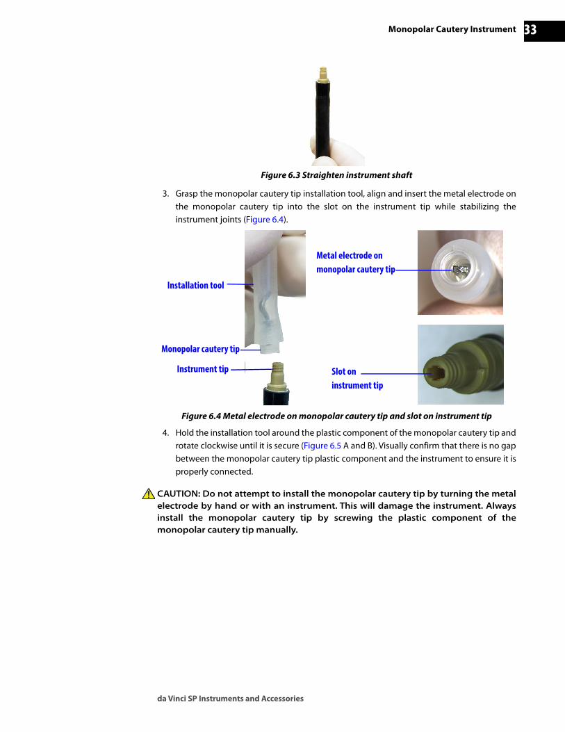
Figure 6.3 Straighten instrument shaft
3. Grasp the monopolar cautery tip installation tool, align and insert the metal electrode on the monopolar cautery tip into the slot on the instrument tip while stabilizing the instrument joints (Figure 6.4).
Figure 6.4 Metal electrode on monopolar cautery tip and slot on instrument tip
4. Hold the installation tool around the plastic component of the monopolar cautery tip and rotate clockwise until it is secure (Figure 6.5 A and B). Visually confirm that there is no gap between the monopolar cautery tip plastic component and the instrument to ensure it is properly connected.
CAUTION: Do not attempt to install the monopolar cautery tip by turning the metal electrode by hand or with an instrument. This will damage the instrument. Always install the monopolar cautery tip by screwing the plastic component of the monopolar cautery tip manually.
Installation tool
Monopolar cautery tip
Instrument tip
Metal electrode on monopolar cautery tip
Slot on instrument tip

Monopolar Cautery Instrument
da Vinci SP Instruments and Accessories
34D
RA
FT/P
RE-
REL
EASE
/CO
NFI
DEN
TIA
L12
/5/1
9
Figure 6.5 Rotate the plastic component of the monopolar cautery tip (A), and confirm it is properly connected (B)
5. Pull up on the installation tool to remove it from the monopolar cautery tip (Figure 6.6 A and B). Retain the installation tool to aid in removing the monopolar cautery tip after the procedure.
Figure 6.6 Pull up on installation tool to remove from monopolar cautery tip (A and B)
6.3 Intraoperative UseRefer to Monopolar Instruments and EnergyShield Monitor Use on page 47, for intraoperative use information.
6.4 Postoperative InstructionsThis section describes information specific to monopolar cautery tip removal. Refer to Postoperative Instructions on page 20, for full postoperative instructions.
Remove the Monopolar Cautery TipRemove the monopolar cautery tip from the instrument after each procedure.
A
Monopolar cautery tip plastic component
B
Properly connected monopolar cautery tip plastic component
BA

da Vinci SP Instruments and Accessories
Monopolar Cautery Instrument 35D
RA
FT/P
RE-
REL
EASE
/CO
NFI
DEN
TIA
L 12
/5/1
9
CAUTION: Do not attempt to remove the monopolar cautery tip by turning the metal electrode by hand or with an instrument. This will damage the instrument. Always remove the monopolar cautery tip by unscrewing the plastic component of the monopolar cautery tip manually.
1. If desired, stabilize the instrument joints and reapply the installation tool onto the plastic component of the monopolar cautery tip (Figure 6.7).
Figure 6.7 Reapply the installation tool
2. Stabilize the instrument joints. Hold the installation tool around the plastic component of the monopolar cautery tip and rotate counter-clockwise until the monopolar cautery tipdisengages from the instrument (Figure 6.8 A and B).
Figure 6.8 Rotate the plastic component of the monopolar cautery tip until disengaged from instrument (A and B)
DisposalDispose of the single-use monopolar cautery tips as biological hazardous waste and according to local hospital protocol.
_________________________________End of section______________________________
BA
Plastic component of the monopolar cautery tip

Bipolar Instruments
da Vinci SP Instruments and Accessories
36D
RA
FT/P
RE-
REL
EASE
/CO
NFI
DEN
TIA
L12
/5/1
9
7 Bipolar Instruments
Note: For general instrument information, see Chapter 3, EndoWrist SP Instruments, starting on page 13.
7.1 IntroductionThe EndoWrist SP bipolar instruments are multiple-use, electrosurgical endoscopic instruments. They are designed to be used in conjunction with the da Vinci SP System and the electrosurgical unit (ESU).
Refer to 3.2 Preoperative Preparation on page 16 for general preoperative instrument information and 3.4 Postoperative Instructions on page 20 for postoperative instructions. Refer to 8.4 Bipolar Cautery on page 57 for intraoperative use information.
Compatibility Information Bipolar instruments are not validated for use with any third-party products.
CAUTION: No EndoWrist SP instruments are validated for use with bulldog clamps.
_________________________________End of section______________________________

da Vinci SP Instruments and Accessories
Using the Electrosurgical Unit (ESU) with Monopolar and Bipolar Instruments 37D
RA
FT/P
RE-
REL
EASE
/CO
NFI
DEN
TIA
L 12
/5/1
9
8 Using the Electrosurgical Unit (ESU) with Monopolar and Bipolar Instruments
8.1 IntroductionThe following sections contain information regarding use of the integrated electrosurgical unit (ERBE VIO® dV 2.0), EnergyShield® Monitor, set up and use of the monopolar and bipolar cautery instruments and troubleshooting.
General Warnings and Cautions
WARNING: Be sure to read and understand all information, particularly caution and warning information, found in the applicable user manuals before using these products. Failure to properly follow all instructions, including instructions supplied with accessory devices such as generators and the applicable user manuals for the da Vinci SP System may lead to injury and result in improper functioning of the device.
WARNING: Do not use electrosurgical instruments in patients who have electronic implants such as cardiac pacemakers without first consulting a qualified professional (for example, a cardiologist). A possible hazard exists because interference with the action of the electronic implant may occur, or the implant may be damaged.
WARNING: Do not use electrosurgical instruments in the presence of flammable anesthetics or oxidizing gases (such as nitrous oxide (N2O) and oxygen) or in close proximity to volatile solvents (such as ether or alcohol), as explosion may occur.
WARNING: Do not place instruments in contact with flammable material (such as gauze or surgical drapes). Instruments that are activated or hot from use may cause a fire.
WARNING: Energy instrument tips may remain hot enough to cause burns after the RF current is deactivated.
WARNING: Connect instrument tips and cautery cords (monopolar and bipolar) only when the energy is off. Failure to do so may result in an injury or electrical shock to the patient or operating room personnel.
WARNING: Do not use any non-integrated ESUs as these are not approved for use with the da Vinci SP System.
WARNING: Do not use any instrument cautery cord other than those approved for use with the da Vinci SP System.

Using the Electrosurgical Unit (ESU) with Monopolar and Bipolar Instruments
da Vinci SP Instruments and Accessories
38D
RA
FT/P
RE-
REL
EASE
/CO
NFI
DEN
TIA
L12
/5/1
9
WARNING: Do not use one instrument to energize the tips of another instrument (robotic or manual laparoscopic). This may cause patient injury and damage to the instrument. Energy may flow to the patient from places other than the tip, inside or outside the field of view. Avoid close proximity to other instrument tips when energizing monopolar instruments.
WARNING: Use the lowest power setting possible for the minimum time necessary to achieve the desired effect.
WARNING: Excessive power or effect levels may result in instrument malfunction and possible patient or user injury. Reduce power or effect setting if any of the following effects are observed: excessive arcing, excessive tissue charring, excessive overheating of the tip (for example, the tip glowing red or emitting a blue plasma cloud).
WARNING: Never increase the effect settings without first checking both the active electrode and the patient neutral pad (grounding pad) and their connections. Use the active electrode or forceps only for the minimum time necessary to achieve the desired surgical effect in order to minimize the possibility of burns.
WARNING: Thermal spread adjacent to target tissue may result in unintended burns to surrounding tissue.
WARNING: Inspect instruments and cables for damage prior to each use, especially the insulation of laparoscopic/endoscopic instruments. This may be done visually under magnification.
WARNING: Visual inspection alone may not be sufficient to ensure that the insulation is intact. The EnergyShield Monitor must be used with monopolar instruments.
WARNING: Do not activate an electrosurgical instrument when not in contact with target tissue, as this may cause injuries due to capacitive coupling with other surgical equipment.
WARNING: Do not attempt to activate an EndoWrist SP instrument via an auxiliary foot pedal.
WARNING: Do not use an instrument to clean debris from another instrument inside the patient. This may result in damage to the instruments or other unintended consequences, such as disconnection of the instrument tip. To clean an instrument intraoperatively, remove the instrument from the system and wipe the instrument tip with moist sterile gauze.

da Vinci SP Instruments and Accessories
Using the Electrosurgical Unit (ESU) with Monopolar and Bipolar Instruments 39D
RA
FT/P
RE-
REL
EASE
/CO
NFI
DEN
TIA
L 12
/5/1
9
CAUTION: To avoid inadvertent thermal damage to surrounding tissue and other hazards, observe the following.
• Ensure that the patient neutral pad is securely affixed to the patient, placed as close as possible to the operating field, and properly connected to the electrosurgical unit.
• For monopolar instruments, always use the lowest output setting that achieves the desired surgical effect. When used with the da Vinci SP System, the VIO dV limits effect settings in certain modes as shown in Table 8-1, on page 42.
• Secure and route the cautery cord to the EndoWrist SP instrument to prevent cord damage and unintended disconnection.
• Avoid patient contact with grounded metal parts.
• Place any monitoring electrodes as far as possible from the surgical electrodes or the patient neutral pad when high frequency (HF) surgical equipment and physiological monitoring equipment are used simultaneously on the same patient.
• Do not use flammable anesthetics or oxidizing gases such as nitrous oxide and oxygen.
• Use only non-flammable agents for cleaning and disinfecting. If flammable agents are used for cleaning or disinfecting or as solvents, they must be allowed to evaporate before application of HF energy.
CAUTION: Ensure that the ESU audible output can be heard by the operating surgeon during ESU use with the da Vinci SP System.
CAUTION: Refer to the ERBE VIO dV User Manual for operating instructions and warning and caution information.
8.2 Integrated ERBE VIO dV 2.0The ERBE VIO dV 2.0 (VIO dV) is an integrated electrosurgical unit that is used with EndoWrist SP instruments and manual instruments. This section provides general information specific to use with the da Vinci SP System and instruments. For further information, including warning and caution information, see the ERBE VIO dV User Manual.
Note: The da Vinci SP System requires use of a dual surface patient neutral pad with the integrated VIO dV.
Note: When using the VIO dV with EndoWrist SP monopolar instruments, the EnergyShield Monitor must be used and properly connected. See Monopolar Instruments and EnergyShield Monitor Use on page 47 for more information.

Using the Electrosurgical Unit (ESU) with Monopolar and Bipolar Instruments
da Vinci SP Instruments and Accessories
40D
RA
FT/P
RE-
REL
EASE
/CO
NFI
DEN
TIA
L12
/5/1
9
VIO dV OverviewESU Screen Features
• Power button: The button that turns the ESU on/off.
• Volume control: Up/down selection buttons that adjust the volume settings.
• Recall: A button that displays when the ESU is first powered on that enables use of previous ESU settings.
• Help menu: A menu that provides descriptions of the CUT & COAG modes and explanations for the icons on the ESU screen. An error log is also available.
• Patient neutral pad status (NESSY): An indicator that provides information about the safety status of the patient neutral pad. When the indicator is green, a valid patient neutral pad is properly connected. When the indicator is red, a valid patient neutral pad is not properly connected.
• Bipolar ports (1 and 2): The ports that are used to connect bipolar instruments to the ESU.
• Monopolar ports (1 and 2): The ports that are used to connect manual monopolar instruments and the EnergyShield Monitor to the ESU. See Connecting the Monopolar Instruments, EnergyShield Monitor and VIO dV on page 50 for more information.
• Neutral port: The port used to connect a patient neutral pad to the ESU to enable monopolar energy. When used with the EnergyShield Monitor (for EndoWrist SP monopolar instruments), the patient neutral pad is connected through the neutral connection on the EnergyShield Monitor. See Connecting the Monopolar Instruments, EnergyShield Monitor and VIO dV on page 50 for more information.
• Mode pods (bipolar and monopolar): The mode pods display settings and selection buttons for applicable instruments. Only the selected mode's settings are displayed.
• Power Limit selection and display: The button that enables users to select a limit on the maximum power delivered for fine-tuned control over tissue effect in each mode; the selected power limit is displayed. Effect can also be adjusted in the power limit window for iterative testing of settings.
• Control assignment indicators (bipolar and monopolar): The control assignment indicators (also referred to as assignment indicators) contain icons that show how instruments can be activated.

da Vinci SP Instruments and Accessories
Using the Electrosurgical Unit (ESU) with Monopolar and Bipolar Instruments 41D
RA
FT/P
RE-
REL
EASE
/CO
NFI
DEN
TIA
L 12
/5/1
9
Note: The VIO dV auxiliary foot pedals (bipolar and monopolar) are connected to the VIO dV and are located in the bottom drawer of the Vision Cart.
Figure 8.1 VIO dV
Loading ScreenPress the Power button on the lower left side of the VIO dV to turn it on. The Loading screen appears.
Main Screen The Main screen displays the default settings shown in Figure 8.2.
Figure 8.2 Main screen with default settings displayed
Bipolar mode pod COAG
Monopolar mode pods CUT & COAG
Power button
Recall Volume control
Help menu
Patient neutral pad status (NESSY)
Bipolar port 1
Assignment indicators (bipolar)
Monopolar port 2
Monopolar port 1
Neutral port
Assignment indicators (monopolar)
Bipolar port 2Power limit selection and display

Using the Electrosurgical Unit (ESU) with Monopolar and Bipolar Instruments
da Vinci SP Instruments and Accessories
42D
RA
FT/P
RE-
REL
EASE
/CO
NFI
DEN
TIA
L12
/5/1
9
Selecting VIO dV Settings
After the VIO dV is powered on, the default effect settings will be zero and must be increased to activate energy. Settings can be selected by recalling previous monopolar and bipolar settings, or by manually adjusting the settings. With either selection method, set the effect as low as possible relative to the desired surgical effect. When used with the da Vinci SP System, the VIO dV limits energy settings to those approved for EndoWrist SP monopolar instruments (see Table 8-1).
Recall Previous Settings
Note: Recalling previous settings is only possible after the ESU is initially powered on, and before settings are manually adjusted.
To load the previous monopolar and bipolar settings, touch the Recall button. The Recallbutton disappears and the previous settings are applied. The settings can then be used or manually adjusted as needed (Figure 8.3).
Figure 8.3 Recall button
Manually Adjust Mode and Effect SettingsTouch to select the mode from the drop-down menu. Set the desired effect using the effect selection arrows (Figure 8.4 and Figure 8.5).
Note: The energy settings can also be adjusted from the Surgeon Console touchpad. For more information, see the da Vinci SP System User Manual.
CAUTION: Changing settings on one monopolar instrument changes settings for all connected monopolar instruments. Changing settings on one bipolar instrument changes settings for all connected bipolar instruments.
Figure 8.4 Mode and effect settings, Monopolar CUT
Table 8-1 Maximum Approved Energy Settings for EndoWrist SP Instruments
ESU Mode Max Effect Setting
VIO dVa
a. All other effect settings in all other monopolar and bipolar modes are approved for use with EndoWrist SP instruments.
Monopolar, Swift Coag 5
Monopolar, Auto Cut 7
Mode selection Effect selection

da Vinci SP Instruments and Accessories
Using the Electrosurgical Unit (ESU) with Monopolar and Bipolar Instruments 43D
RA
FT/P
RE-
REL
EASE
/CO
NFI
DEN
TIA
L 12
/5/1
9
Figure 8.5 Mode and effect settings, Monopolar COAG
Bipolar and Monopolar Instrument ActivationBipolar and monopolar instruments (EndoWrist SP and manual) can be activated using the specified ports (as shown with [X] in the tables below).
Manually Adjust Power Limit SettingsIn addition to adjusting mode and effect settings, users can adjust power limit settings (Figure 8.6). Power limit settings enable users to adjust the limit on the maximum power delivered for fine-tuned control over tissue effect in each energy mode. Adjusting power limits changes the potential range of power fluctuation.
1. Touch the Power Limit button to open the power limit settings window.
2. Use the left and right arrow buttons to select the required limit.
The power limit can be reset to the factory default using the Default button.
The effect can also be adjusted, using the effect selection arrows in this window.
3. Touch Close to return to the main screen.
Table 8-2 Bipolar Instrument Activation
Port EndoWrist SP Bipolar
Instruments
Manual Bipolar Instruments
(Foot pedal activated)Bipolar Port 1 X
Bipolar Port 2 X X
Table 8-3 Monopolar Instrument Activation
Port EndoWrist SP Monopolar
Instrumentsa
a. EndoWrist SP monopolar instruments are connected to the VIO dV through the EnergyShield Monitor.
Manual Monopolar Instruments
(Foot pedal activated)
Manual Monopolar Instruments
(Fingerswitch activated)Monopolar port 1 X X
Monopolar port 2 X X X
Mode selection Effect selection

Using the Electrosurgical Unit (ESU) with Monopolar and Bipolar Instruments
da Vinci SP Instruments and Accessories
44D
RA
FT/P
RE-
REL
EASE
/CO
NFI
DEN
TIA
L12
/5/1
9
Figure 8.6 Power limit settings, Monopolar COAG example
Power limit settings can also be adjusted on the Surgeon Console touchpad. For instructions, see the da Vinci SP System User Manual.
Presets
On the Surgeon Console touchpad, users can save up to three preferred sets of energy settings (presets) to an account. Presets include all mode, effect, and power limit settings for both monopolar and bipolar energy types.
For details on saving and applying energy presets, see the da Vinci SP System User Manual.
Power Limit button
Effect selection
Power Limit selection

da Vinci SP Instruments and Accessories
Using the Electrosurgical Unit (ESU) with Monopolar and Bipolar Instruments 45D
RA
FT/P
RE-
REL
EASE
/CO
NFI
DEN
TIA
L 12
/5/1
9
Control Assignment IndicatorsThe control assignment indicators (also referred to as assignment indicators) contain icons that specify how the instruments connected to the ports can be activated. Each port is associated with the adjacent assignment indicator (as shown in Figure 8.7). If an EndoWrist SP instrument is connected to the associated port, the icon indicates the following:
• whether or not the instrument is completely connected and,
• if connected, the drive on which the connected instrument is installed.
If an EndoWrist SP instrument is not installed, the icon indicates whether or not the port can be activated from the auxiliary foot pedals. For more information, see the ERBE VIO dV User Manual.
Figure 8.7 Control Assignment indicators
The numbers shown in the assignment indicator icons correspond to specific instrument drives (1, 2 or 3) on the instrument arm.

Using the Electrosurgical Unit (ESU) with Monopolar and Bipolar Instruments
da Vinci SP Instruments and Accessories
46D
RA
FT/P
RE-
REL
EASE
/CO
NFI
DEN
TIA
L12
/5/1
9
Assignment Indicator Icon DescriptionsThe following table describes the icons that appear in the monopolar and bipolar control assignment indicators.
Table 8-4 Control Assignment Indicator Icons
Icon Meaning
Good EndoWrist SP instrument connection (monopolar or bipolar)
An EndoWrist SP instrument is connected to the port and installed on an instrument drive. The number corresponds to the instrument drive on which the connected instrument is installed. Activation of an EndoWrist SP instrument is possible.
Incomplete EndoWrist SP instrument connection (monopolar or bipolar)
Monopolar• There is a broken connection between the VIO dV, EnergyShield Monitor, and the
EndoWrist SP instrument installed on the instrument drive, or
• The EndoWrist SP instrument is connected to the EnergyShield Monitor and VIO dV, but is not installed on an instrument drive.
Bipolar• The EndoWrist SP instrument is installed on an instrument drive but is not connected to the
VIO dV, or
• The EndoWrist SP instrument is connected to the VIO dV, but is not installed on an instrument drive.
Activation of the EndoWrist SP instruments is not possible until the connection is completed and the instrument is installed onto an instrument drive.
Non-EndoWrist SP instrument local activation only • No EndoWrist SP instrument connected.
• Connected monopolar manual laparoscopic instrument can only be activated by switches on the instrument (such as local fingerswitches).
• If this icon appears in the monopolar port 2 or bipolar port 2 assignment indicator, the monopolar or bipolar foot pedal is not connected.
For bipolar port 2 only• No EndoWrist SP instrument connected.
• Connected bipolar manual laparoscopic instrument can be activated by auxiliary bipolar foot pedal.
For monopolar port 2 only• No EndoWrist SP instrument connected.
• Connected monopolar manual laparoscopic instrument can be activated by auxiliary foot pedal.
• Connected monopolar manual laparoscopic instrument can be activated by switches on the instrument (such as local fingerswitches).

da Vinci SP Instruments and Accessories
Using the Electrosurgical Unit (ESU) with Monopolar and Bipolar Instruments 47D
RA
FT/P
RE-
REL
EASE
/CO
NFI
DEN
TIA
L 12
/5/1
9
ERBE VIO dV 2.0 Fault ConditionsFour ERBE VIO dV 2.0 fault conditions related to da Vinci SP energy instruments result in system messages displayed on the Vision Cart touchscreen, above the instrument status pod, and in the 3D viewer. Also, error tones sound at the Surgeon Console and Patient Side Cart. Refer to Table 8-5 for the message descriptions.
For further information on troubleshooting VIO dV fault conditions, see the ERBE VIO dV User Manual.
8.3 Monopolar Instruments and EnergyShield Monitor UseThis section discusses Monopolar Instruments and EnergyShield Monitor Use:
• General Warnings and Cautions-Monopolar Instruments
• EnergyShield Monopolar Cautery Cord
• Connecting the Monopolar Instruments, EnergyShield Monitor and VIO dV
• Intraoperative Use
• Intraoperative Cleaning
General Warnings and Cautions-Monopolar Instruments
WARNING: Do not use monopolar instruments with a bipolar source output as this may cause damage to the instrument and harm to the patient or medical personnel.
WARNING: Do not use one instrument to energize the tips of another instrument (robotic or manual laparoscopic). This may cause patient injury and damage to the instrument. Energy may flow to the patient from places other than the tip, inside or outside the field of view. Avoid close proximity to other instrument tips when energizing monopolar instruments.
Table 8-5 ERBE VIO dV Fault Conditions and System Message Descriptions
Instrument Type ERBE VIO dV 2.0 Fault Condition System Message Description Icon
Bipolar
C-84: Energy activation has been interrupted due to detection of a short circuit condition between active and neutral electrodes on bipolar instruments. This can occur when there is not enough tissue between the jaws of the instrument and the AutoStop feature is turned ON.
Regrasp tissue or ensure jaw separation. Short detected.
Monopolar
M-0B: Energy is being activated while the patient neutral pad is not connected to the EnergyShield Monitor, is defective, has poor contact with the patient, or when the neutral adapter is not connected to the VIO dV.
Check one or more of the following:• Dual neutral pad and
connection• Contact with patient• Neutral adapter connection
M-1F: Energy is being activated while the patient neutral pad is not oriented in the proper direction (the long edge is not pointing toward the operating field).
Check dual neutral pad orientation and contact with patient.
Bipolar or Monopolar
M-1C: Energy activation is halted when energy activation time has been exceeded.
Timeout reached.

Using the Electrosurgical Unit (ESU) with Monopolar and Bipolar Instruments
da Vinci SP Instruments and Accessories
48D
RA
FT/P
RE-
REL
EASE
/CO
NFI
DEN
TIA
L12
/5/1
9
WARNING: Do not touch the tips while electrosurgical energy is activated as this may cause severe electrical injury and/or burn to the user.
WARNING: The patient neutral pad must be properly affixed to the patient before the use of monopolar cautery, to prevent patient or operator injury.
WARNING: Do not bypass the EnergyShield Monitor while using EndoWrist SP monopolar instruments by connecting the patient neutral pad directly to the ESU. ESU operation is prevented if the patient neutral pad is not connected to the EnergyShield Monitor.
WARNING: Aspirate fluid from the area before activating the monopolar instrument. Conductive fluids (such as blood or saline) in direct contact with or in close proximity to an active electrode may carry electrical current or heat away from target tissues, which may cause unintended burns to the patient.
WARNING: Prior to increasing the intensity, check the adherence of the patient neutral pad and its connections. Apparent low output or failure of the device to function correctly at the normal operating settings may indicate faulty application of the patient neutral pad or poor contact in its connections.
WARNING: Loss of safe contact between the patient neutral pad and the patient will not result in an alarm unless a compatible monitoring patient neutral pad is used.
WARNING: During heavy intraoperative cautery application, it may be possible for tissue char to cause the blades to stick together or to reduce cutting performance. Should this occur, remove the instrument and clean the blades with moist gauze or a scrub pad.
WARNING: While activating monopolar energy, be aware of anatomy that is in contact with the instrument wrist or shaft. The instrument should not be used as a retractor while applying energy.
WARNING: Avoid routing the monopolar and bipolar energy cords close together. Doing so may increase the risk of stray cautery from the bipolar instrument due to capacitive coupling between the cords.
CAUTION: The EndoWrist SP monopolar electrosurgical instruments are designed for use with a maximum peak voltage of 3kV (6kV peak-to-peak). Only compatible electrosurgical units have been tested to ensure that they do not exceed this limit. Do not attempt to use instruments with electrosurgical units that are not compatible with the da Vinci SP System.

da Vinci SP Instruments and Accessories
Using the Electrosurgical Unit (ESU) with Monopolar and Bipolar Instruments 49D
RA
FT/P
RE-
REL
EASE
/CO
NFI
DEN
TIA
L 12
/5/1
9
EnergyShield Monopolar Cautery Cord The reusable EnergyShield Monopolar Cautery Cord (PN 430068) is intended to be used in conjunction with the VIO dV generator, EnergyShield Monitor and EndoWrist SP monopolar instruments with the appropriate connector (Figure 8.8). The cord is supplied non-sterile and requires cleaning and sterilization before use. For more information regarding cleaning and sterilization, refer to the Reprocessing Instructions.
Figure 8.8 EnergyShield monopolar cautery cord connectors
Inspection
Inspect cord for damage or irregularities before and after each use. Visually inspect the cord for physical damage including:
• Cracked, broken, or otherwise distorted parts
• Broken or significantly bent connector contacts
• Punctures, cuts, nicks, abrasions, unusual bumps, or significant discoloration
• Corrosion of connector contacts
Wide connector
Instrument connector

Using the Electrosurgical Unit (ESU) with Monopolar and Bipolar Instruments
da Vinci SP Instruments and Accessories
50D
RA
FT/P
RE-
REL
EASE
/CO
NFI
DEN
TIA
L12
/5/1
9
EnergyShield Monitor OverviewThe EnergyShield Monitor provides monitoring of electrosurgical energy during use of EndoWrist SP monopolar instruments, which are shielded to reduce the risks of capacitive coupling. The EnergyShield Monitor terminates energy delivery when a fault condition is detected on the connected monopolar instrument, such as:
• Loss of instrument shield integrity
• Breakdown of internal instrument insulation
• Loss of Instrument Sheath integrity (only in certain conditions)
WARNING: The EnergyShield Monitor will not detect all occurrences of damage to the monopolar instrument sheath. Inspect the Instrument Sheath for damage throughout use. Examples of damage include tears or cuts in the sheath material. If damage is observed, remove and replace the Instrument Sheath on any instrument (monopolar or other) to prevent stray cautery or other risks.
For more information on troubleshooting the EnergyShield Monitor, see EnergyShield Monitor Faults and Failure on page 54.
Connecting the Monopolar Instruments, EnergyShield Monitor and VIO dVThis section describes how the EnergyShield Monitor works with the da Vinci SP System and connects to the EndoWrist SP monopolar instruments and the VIO dV.
Note: The EnergyShield Monitor should remain powered on. When the da Vinci SP System is powered off, the EnergyShield Monitor is in a sleep state with all LEDs off. The EnergyShield Monitor will start up with the da Vinci SP System when it is powered on.
Note: The da Vinci SP System should be powered on before the monopolar cord is connected to the EnergyShield Monitor to enable the EnergyShield Monitor to complete all self-tests.
1. If not already on, power on the da Vinci SP System. The EnergyShield Monitor performs a self-test. After the self-test completes, the Instrument LED and Sheath LED illuminate blue and the Neutral Pad LED and Cord LED illuminate amber (Figure 8.9).
Figure 8.9 EnergyShield Monitor self test complete
2. Ensure that the VIO dV is plugged into the appropriate power receptacle and powered on.
Neutral Pad LED Instrument LED Sheath LEDCord LED

da Vinci SP Instruments and Accessories
Using the Electrosurgical Unit (ESU) with Monopolar and Bipolar Instruments 51D
RA
FT/P
RE-
REL
EASE
/CO
NFI
DEN
TIA
L 12
/5/1
9
3. Verify that the neutral adapter from the EnergyShield Monitor is plugged into the neutral port on the VIO dV (Figure 8.10). Confirm that the connector cannot be pushed further into the neutral port.
Figure 8.10 Check EnergyShield Monitor neutral adapter and monopolar adapter connections to VIO dV
Note: The neutral adapter from the EnergyShield Monitor can remain plugged into the neutral port on the VIO dV to enable use of manual instruments with the VIO dV, even in the event of an EnergyShield Monitor fault.
Note: Only monopolar port 2 can be used for manual monopolar instruments that are activated by the auxiliary foot pedal.
4. Verify that the monopolar adapter from the EnergyShield Monitor is plugged into a monopolar port on the VIO dV (Figure 8.10).
5. Remove the patient neutral pad from the package and place the pad in the preferred location on the patient. See Patient Neutral Pad Positioning on page 62 for more information.
Monopolar adapter from EnergyShield Monitor
Neutral adapter from EnergyShield Monitor

Using the Electrosurgical Unit (ESU) with Monopolar and Bipolar Instruments
da Vinci SP Instruments and Accessories
52D
RA
FT/P
RE-
REL
EASE
/CO
NFI
DEN
TIA
L12
/5/1
9
6. Connect the patient neutral pad plug into the neutral receptacle on the EnergyShield Monitor (Figure 8.11). Verify that the Neutral Pad LED illuminates blue and the patient neutral pad icon on the VIO dV illuminates green.
Figure 8.11 Patient pad plugged into EnergyShield Monitor
WARNING: Do not bypass the EnergyShield Monitor while using EndoWrist SP monopolar instruments by connecting the patient neutral pad directly to the ESU. ESU operation is prevented if the patient neutral pad is not connected to the EnergyShield Monitor (Figure 8.12).
Figure 8.12 Do not connect the patient neutral pad directly to the VIO dV
7. Obtain the monopolar instrument and confirm that the cautery tip and Instrument Sheath are installed. Connect the instrument connector end of the EnergyShield monopolar cautery cord to the EndoWrist SP monopolar instrument housing. The connector is properly seated when it cannot be pushed further into the housing.
Patient Neutral Pad

da Vinci SP Instruments and Accessories
Using the Electrosurgical Unit (ESU) with Monopolar and Bipolar Instruments 53D
RA
FT/P
RE-
REL
EASE
/CO
NFI
DEN
TIA
L 12
/5/1
9
Note: It is recommended to have a backup EndoWrist SP monopolar instrument available for use to minimize procedure delay in the event of an instrument-related EnergyShield Monitor fault.
8. Align the arrow on the wide connector end of the monopolar cautery cord with the arrow above the monopolar receptacle on the EnergyShield Monitor (Figure 8.13) and plug it in. Ensure that the monopolar cautery cord is fully seated by verifying that the connector cannot be pushed further into the receptacle. When both ends of the monopolar cautery cord are properly connected to the EndoWrist SP monopolar instrument and EnergyShield Monitor, the cord LED on the EnergyShield Monitor illuminates blue (Figure 8.13).
Figure 8.13 All LEDs illuminated blue9. Confirm all four LEDs illuminate blue (as shown in Figure 8.14) before using the
monopolar instrument.
Figure 8.14 Blue LEDs confirmation
For more information on EndoWrist SP monopolar instruments, see Chapter 5 Monopolar Curved Scissors starting on page 25 and Chapter 6 Monopolar Cautery Instrument starting on page 31.
Cord LED
Arrow above the monopolar receptacle
Monopolar adapter from EnergyShield Monitor
Neutral adapter from EnergyShield Monitor
Patient Neutral Pad
EnergyShield Monopolar Cautery Cord

Using the Electrosurgical Unit (ESU) with Monopolar and Bipolar Instruments
da Vinci SP Instruments and Accessories
54D
RA
FT/P
RE-
REL
EASE
/CO
NFI
DEN
TIA
L12
/5/1
9
EnergyShield Monitor Faults and Failure
WARNING: The EnergyShield Monitor will not detect all occurrences of damage to the monopolar instrument sheath. Inspect the Instrument Sheath for damage throughout use. Examples of damage include tears or cuts in the sheath material. If damage is observed, remove and replace the Instrument Sheath on any instrument (monopolar or other) to prevent stray cautery or other risks.
If the EnergyShield Monitor detects a fault condition, the system emits an audible tone upon the user attempting to activate monopolar energy and upon occurrence of an instrument or a sheath fault, and the associated LED(s) on the front panel illuminate amber. During EnergyShield Monitor faults, energy activation of EndoWrist SP monopolar instruments is prevented from the Surgeon Console, but energy activation of EndoWrist SP bipolar instruments and manual instruments (footswitch or auxiliary foot pedal activated) is permitted. All system control modes (including Following mode for installed instruments) remain available during an EnergyShield Monitor fault.
If at any time the EnergyShield Monitor does not function as described, discontinue use of the EnergyShield Monitor and contact Intuitive Surgical Customer Service.
EnergyShield Monitor Faults
If an EnergyShield Monitor fault can be resolved by the user, solid amber LED(s) on the EnergyShield Monitor indicate the source of the fault (Figure 8.15). When the user attempts to activate monopolar energy in a fault condition, the system also emits a temporary audible tone and an error message displays above the instrument drive pod associated with the installed EndoWrist SP monopolar instrument (Figure 8.16).
Figure 8.15 EnergyShield Monitor
See Table 8-6 for more information to identify and resolve faults. If a cord, instrument, or sheath fault does not resolve after following the corresponding steps in Table 8-6, replace the remaining components not yet replaced (for example, cord, instrument, or sheath). If the fault does not resolve, contact Intuitive Surgical Customer Service.
Figure 8.16 Error message above instrument drive pod example
Neutral Pad LED Instrument LED Sheath LEDCord LED

da Vinci SP Instruments and Accessories
Using the Electrosurgical Unit (ESU) with Monopolar and Bipolar Instruments 55D
RA
FT/P
RE-
REL
EASE
/CO
NFI
DEN
TIA
L 12
/5/1
9 EnergyShield Monitor Failure
An internal EnergyShield Monitor failure that cannot be resolved by the user is indicated by all four LEDs blinking amber (Figure 8.17). A system message also displays across the top of the surgical view (Figure 8.18).
Figure 8.17 All LEDs illuminated amber
Figure 8.18 EnergyShield Monitor fault system message
Table 8-6 EnergyShield Monitor Faults
EnergyShield MonitorAmber LED
EnergyShield MonitorStatus
Troubleshooting Steps
Neutral Pad Dual-surface patient neutral pad not connected to EnergyShield Monitor
Ensure that a dual-surface patient neutral pad is applied to the patient. Connect the patient neutral pad to the neutral receptacle of the EnergyShield Monitor.
Cord Monopolar cautery cord connection interrupted
Connect the monopolar cautery cord to the monopolar instrument installed on the da Vinci SP System and to the monopolar receptacle of the EnergyShield Monitor.
a. If fault persists, replace the monopolar cautery cord with a backup monopolar cautery cord. If fault resolves following cord replacement, dispose of the faulty monopolar cautery cord.
b. If fault persists following cord replacement, replace the monopolar instrument with a backup monopolar instrument. If fault resolves following instrument replacement, dispose of faulty monopolar instrument.
Instrument Internal instrument insulation compromised
Replace the monopolar instrument with backup monopolar instrument. Dispose of faulty monopolar instrument.
Sheath Instrument Sheath integrity compromised
In the event of an Instrument Sheath fault, it is recommended to inspect the surgical site, including the area outside of the surgical view, for any stray burns, as damage to the Instrument Sheath may result in stray cautery.
Replace the Instrument Sheath on the monopolar instrument with a new, unused Instrument Sheath.

Using the Electrosurgical Unit (ESU) with Monopolar and Bipolar Instruments
da Vinci SP Instruments and Accessories
56D
RA
FT/P
RE-
REL
EASE
/CO
NFI
DEN
TIA
L12
/5/1
9
If this type of EnergyShield Monitor failure occurs, the EnergyShield Monitor may be non-functional and should not be used. The system will trigger a system recoverable fault (Figure 8.19) which can be recovered to resume all system control modes and bipolar energy activation of the VIO dV, but energy activation of EndoWrist SP monopolar instruments will be prevented from the Surgeon Console. If this occurs, contact Intuitive Surgical Customer Service.
Figure 8.19 Recoverable fault message example
Intraoperative UseWARNING: Do not use monopolar instruments with a bipolar source output as this may cause damage to the instrument and harm to the patient or medical personnel.
WARNING: Use the lowest power setting possible for the minimum time necessary to achieve the desired effect.
WARNING: Excessive power or effect levels may result in instrument malfunction and possible patient or user injury. Reduce power or effect setting if any of the following effects are observed: excessive arcing, excessive tissue charring, excessive overheating of the tip (for example, the tip glowing red or emitting a blue plasma cloud).
WARNING: Exercise caution when working with monopolar instruments close to other instruments. Unintended energy may be delivered from the active monopolar instrument to a second instrument (EndoWrist SP or manual laparoscopic). This could result in burns to tissue in contact with any of the second instrument's metal parts or port. To exercise caution in these scenarios, the monopolar tip should be closer to the tissue than to the second instrument.
WARNING: The Monopolar Cautery Instrument should be cleaned and dried before installing or exchanging any monopolar cautery tip.
WARNING: As with any electrosurgical device, it is possible for energy to discharge in an area other than the instrument tip. It is important to exercise caution when using an energized EndoWrist SP cautery instrument to help avoid unintended contact with tissue adjacent to the area to be cauterized.
WARNING: Inspect the Instrument Sheath for damage throughout use. Examples of damage include tears or cuts in the sheath material. If damage is observed, remove and replace the Instrument Sheath on any instrument (monopolar or other) to prevent stray cautery or other risks.

da Vinci SP Instruments and Accessories
Using the Electrosurgical Unit (ESU) with Monopolar and Bipolar Instruments 57D
RA
FT/P
RE-
REL
EASE
/CO
NFI
DEN
TIA
L 12
/5/1
9
CAUTION: If the MCS Tip becomes loose during use DO NOT use another instrument to remove the accessory inside the patient. Close the MCS blades, remove the instrument from the port, and replace the MCS Tip with a new one.
Monopolar instruments are rated for a maximum peak voltage of 3kV (6kV peak-to-peak).
1. Touch the target tissue to be cut or coagulated with the tip of the monopolar instrument. Make sure that the tip does not come in contact with non-target tissue.
2. Activate the ESU by depressing the associated instrument foot pedal at the Surgeon Console.
3. After cutting or coagulating is complete, visually inspect the surgical area to ensure adequate hemostasis.
Intraoperative Cleaning
WARNING: Use care not to twist the MCS Tip when carefully cleaning the Monopolar Curved Scissors intraoperatively. Twisting may cause the MCS Tip to loosen.
WARNING: Do not use an instrument to clean debris from another instrument inside the patient. This may result in damage to the instruments or other unintended consequences, such as disconnection of the instrument tip. To clean an instrument intraoperatively, remove the instrument from the system and wipe the instrument tip with moist sterile gauze.
CAUTION: Keep the active electrodes clean. Build-up of eschar may reduce the instrument's effectiveness. Do not activate the instrument while cleaning. Injury to operating room personnel may result.
If the tips are contaminated by carbonized tissue, remove the instrument and use a piece of soft gauze moistened with saline or sterile water to remove the tissue.
8.4 Bipolar CauteryThis section contains instructions for use specific to connecting the EndoWrist SP bipolar instruments with the VIO dV and bipolar instrument settings.
This section discusses the following topics:
• Bipolar Cautery Cord
• Connecting Bipolar Instruments to the VIO dV
• Intraoperative Use
• Intraoperative Cleaning
Bipolar Cautery CordThis section provides details specific to the Bipolar Cautery Cord (PN 470384). The reusable cord is supplied non-sterile and requires cleaning and sterilization before use. For more information regarding cleaning and sterilization, refer to the Reprocessing Instructions.
General Warnings and Cautions
WARNING: Never use the cords when there is visible evidence of damage to the exterior, such as a cracked or damaged connector.

Using the Electrosurgical Unit (ESU) with Monopolar and Bipolar Instruments
da Vinci SP Instruments and Accessories
58D
RA
FT/P
RE-
REL
EASE
/CO
NFI
DEN
TIA
L12
/5/1
9
CAUTION: Connect the ESU to the EndoWrist SP instrument using the appropriate monopolar/bipolar cord. Refer to the ESU’s manual for indications and instructions in making this connection. Monopolar cords may only be connected to monopolar ports, and bipolar cords to bipolar ports.
Device DescriptionThe reusable Bipolar Cautery Cord (PN 470384) is designed to be used as an accessory to the EndoWrist SP bipolar instruments in conjunction with the VIO dV generator during surgical and other medical procedures.
Figure 8.20 Bipolar cautery cord connectors
InspectionInspect cords for damage or irregularities before and after each use. Visually inspect the cords for physical damage including:
• Cracked, broken, or otherwise distorted parts
• Broken or significantly bent connector contacts
• Punctures, cuts, nicks, abrasions, unusual bumps, or significant discoloration
• Corrosion of connector contacts
Wide connector
Instrument connector

da Vinci SP Instruments and Accessories
Using the Electrosurgical Unit (ESU) with Monopolar and Bipolar Instruments 59D
RA
FT/P
RE-
REL
EASE
/CO
NFI
DEN
TIA
L 12
/5/1
9
Connecting Bipolar Instruments to the VIO dV1. Connect the energy cord to the EndoWrist SP instrument: Connect the instrument
connector on the energy cord to the applicable EndoWrist SP instrument. The instrument connector is properly seated when it cannot be pushed further into the instrument housing.
2. Correctly orient the wide connector: The wide depression in the connector and the molded arrow should be facing up when installing the cable into the VIO dV port (Figure 8.21).
Figure 8.21 Correct orientation of the connector with molded arrow facing up
3. Connect the energy cord to the VIO dV port: Push the connector into the bipolar port until it cannot be pushed further and is fully seated (Figure 8.21).
For more information on EndoWrist SP bipolar instruments, see Chapter 7 Bipolar Instruments on page 36.
Intraoperative UseBipolar instruments are rated for a maximum peak voltage of 500V.
WARNING: Do not touch the end effectors of the instrument to any staples, clips, or sutures while energized. Damage to the end effectors may occur.
WARNING: Do not attempt to scrape off carbonized tissue with a sharp object such as a scalpel.
WARNING: Do not use bipolar instruments with a monopolar source as this may cause damage to the instrument and harm to the patient or medical personnel.
CAUTION: The EndoWrist SP bipolar electrosurgical instruments are designed for use with a maximum peak voltage of 500V. Only compatible electrosurgical units have been tested to ensure that they do not exceed this limit. Do not attempt to use instruments with electrosurgical units that are not compatible with the da Vinci SP System.
1. Grasp the tissue to be cut or coagulated using the hand control (master) on the Surgeon Console. Make sure that the jaws do not come in contact with non-target tissue.
2. Activate the ESU by depressing the associated foot pedal at the Surgeon Console. To coagulate tissue, the two grips of the bipolar instruments must not come in contact with each other. If the tissue is thin and no coagulation occurs, open the grips slightly, press the bipolar foot pedal, and then close the grips to cauterize the tissue. It may also be possible to coagulate very thin structures by directly applying monopolar energy to the tissue.
Molded arrow
Wide depression

Using the Electrosurgical Unit (ESU) with Monopolar and Bipolar Instruments
da Vinci SP Instruments and Accessories
60D
RA
FT/P
RE-
REL
EASE
/CO
NFI
DEN
TIA
L12
/5/1
9
WARNING: Do not use one instrument to energize the tips of another instrument (robotic or manual laparoscopic). This may cause patient injury and damage to the instrument. Energy may flow to the patient from places other than the tip, inside or outside the field of view. Avoid close proximity to other instrument tips when energizing monopolar instruments.
3. After coagulating is complete, visually inspect the surgical area to ensure adequate hemostasis.
Intraoperative Cleaning
WARNING: Do not use an instrument to clean debris from another instrument inside the patient. This may result in damage to the instruments or other unintended consequences, such as disconnection of the instrument tip. To clean an instrument intraoperatively, remove the instrument from the system and wipe the instrument tip with moist sterile gauze.
CAUTION: Keep the active electrodes clean. Build-up of eschar may reduce the instrument's effectiveness. Do not activate the instrument while cleaning. Injury to operating room personnel may result.
If the tips are contaminated by carbonized tissue, remove the instrument and use a piece of soft gauze moistened with saline or sterile water to remove the tissue.
8.5 TroubleshootingThis section discusses the following topics:
• Monopolar and Bipolar Instrument Energy Delivery
• Patient Neutral Pad Positioning
Monopolar and Bipolar Instrument Energy DeliveryTable 8-7 describes troubleshooting information to help you address energy delivery issues when using the EndoWrist SP monopolar and bipolar instruments. If troubleshooting does not resolve the energy delivery issue, contact Intuitive Surgical Customer Service.

da Vinci SP Instruments and Accessories
Using the Electrosurgical Unit (ESU) with Monopolar and Bipolar Instruments 61D
RA
FT/P
RE-
REL
EASE
/CO
NFI
DEN
TIA
L 12
/5/1
9
Table 8-7 Troubleshooting Monopolar and Bipolar Instrument Energy Delivery
Possible Problems RemedyMonopolar and Bipolar Instruments
VIO dV not powered on or mode effect not set
• Confirm that the VIO dV is powered on.
• Verify that the mode effect setting is higher than zero. Effect settings default to zero.
Cautery cord connections • Verify all cautery cord connections. See Connecting the Monopolar Instruments, EnergyShield Monitor and VIO dV and Connecting Bipolar Instruments to the VIO dV.
• Confirm that the correct cautery cord is connected to the correct instrument. See EnergyShield Monopolar Cautery Cord and Bipolar Cautery Cord.
• Use an alternate port to connect the instrument to the VIO dV.
• Replace the cautery cord with a backup cautery cord.
Instrument connection • Confirm that the instrument is installed on the system.
• Check the icon on the VIO dV to ensure proper instrument connection. See Control Assignment Indicators.
Incorrect foot pedal being used
• Confirm that correct pedal is being pressed at the Surgeon Console. See Bipolar and Monopolar Instrument Activation.
Activation is disabled Confirm the following:
• The VIO dV is connected to the da Vinci SP System and powered on.
• The foot pedals are enabled.
• The mode effect setting is higher than zero. Effect settings default to zero.
• The installed instrument is inserted past the distal edge of the Entry Guide of the port.
• The installed instrument is connected to the VIO dV.
• The surgeon's head is in the 3D viewer.
• The installed instrument is associated with a hand control.
Monopolar Instruments OnlyEnergyShield Monitor not powered on, improperly
connected, or faulted
• Confirm that the EnergyShield Monitor is powered on and not faulted. See EnergyShield Monitor Faults and Failure.
• Verify EnergyShield Monitor connections. See Connecting the Monopolar Instruments, EnergyShield Monitor and VIO dV.
Patient neutral pad error(red patient neutral pad
status on the VIO dV)
• Confirm that a dual surface patient neutral pad is being used.
• Verify patient neutral pad placement.
• Verify that the patient neutral pad is connected to the EnergyShield Monitor and that the neutral adapter connection between the EnergyShield Monitor and VIO dV is secure. See Connecting the Monopolar Instruments, EnergyShield Monitor and VIO dV.
Bipolar Instruments OnlyImproper connection of
instrument to VIO dV• Confirm that the wide connector end of the bipolar cautery cord is oriented with the
molded arrow side facing up, and is properly connected to the VIO dV. See Connecting Bipolar Instruments to the VIO dV.

Using the Electrosurgical Unit (ESU) with Monopolar and Bipolar Instruments
da Vinci SP Instruments and Accessories
62D
RA
FT/P
RE-
REL
EASE
/CO
NFI
DEN
TIA
L12
/5/1
9
Patient Neutral Pad PositioningIt is possible to get patient neutral pad positioning errors on the VIO dV, especially when not using the ERBE patient neutral pads. For more information on proper patient neutral pad positioning, refer to the ERBE VIO dV User Manual.
______________________________End______________________________

da Vinci SP Instruments and Accessories
da Vinci SP Port Accessories 63D
RA
FT/P
RE-
REL
EASE
/CO
NFI
DEN
TIA
L 12
/5/1
9
9 da Vinci SP Port Accessories
9.1 IntroductionThis section contains instructions for use specific to the da Vinci SP® port accessories (da Vinci SP Cannula, da Vinci SP Obturator, and EntryGuide™ Kit) used with the da Vinci SP System.
Note: Reusable SP Cannulas and obturators are shipped non-sterile unless otherwise indicated in the device’s labeling. Clean and sterilize before use.
Intended UseFor intended use of the port accessories, see Appendix D: Intended Use Statements.
Cautions for Single-Use Items
CAUTION: DO NOT RE-STERILIZE. DO NOT RE-USE.
Reprocessing and/or reuse of products intended for single use only may result in degraded instrument performance or loss of functionality, and in exposure to viral, bacterial, fungal, or prionic pathogens.
CAUTION: Do not use if package is damaged.
CAUTION: A breach in the sterile packaging of the device indicates possible contamination. Do not use the device if the packaging is not intact.
9.2 Device Description
Compatibility InformationTable 9-1 shows compatible products used with the da Vinci SP System.
Table 9-1 da Vinci SP Port Accessory Compatibility
SP Cannula PN SP Obturator PN EntryGuide Kit PN
SP Cannula, Circular, 25 mm x 100 mm (430036)
SP Obturator, Circular, 25 mm x 100 mm (430016)
EntryGuide Kit C.6.6.6, 25 mm x 100 mm (includes EntryGuide Cannula Insert and EntryGuide Cannula Seal)(430022)
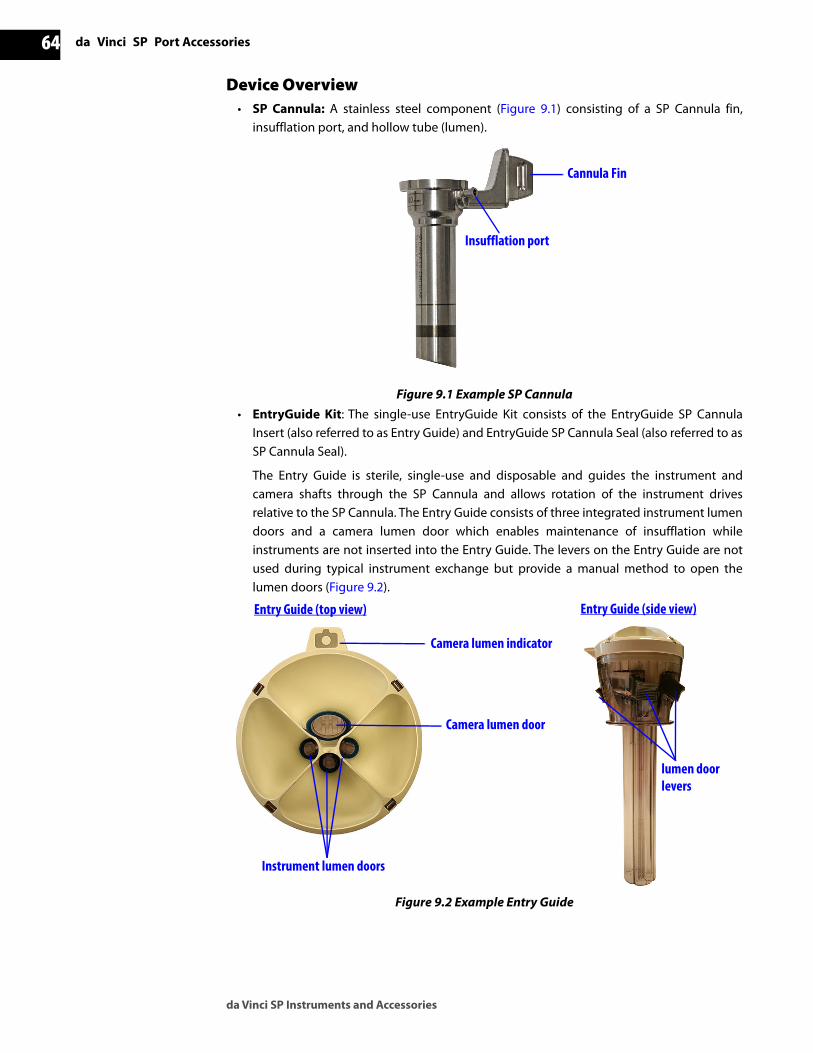
da Vinci SP Port Accessories
da Vinci SP Instruments and Accessories
64D
RA
FT/P
RE-
REL
EASE
/CO
NFI
DEN
TIA
L12
/5/1
9
Device Overview• SP Cannula: A stainless steel component (Figure 9.1) consisting of a SP Cannula fin,
insufflation port, and hollow tube (lumen).
Figure 9.1 Example SP Cannula• EntryGuide Kit: The single-use EntryGuide Kit consists of the EntryGuide SP Cannula
Insert (also referred to as Entry Guide) and EntryGuide SP Cannula Seal (also referred to as SP Cannula Seal).
The Entry Guide is sterile, single-use and disposable and guides the instrument and camera shafts through the SP Cannula and allows rotation of the instrument drives relative to the SP Cannula. The Entry Guide consists of three integrated instrument lumen doors and a camera lumen door which enables maintenance of insufflation whileinstruments are not inserted into the Entry Guide. The levers on the Entry Guide are not used during typical instrument exchange but provide a manual method to open the lumen doors (Figure 9.2).
Figure 9.2 Example Entry Guide
Insufflation port
Cannula Fin
Camera lumen door
Camera lumen indicator
Instrument lumen doors
lumen door levers
Entry Guide (top view) Entry Guide (side view)

da Vinci SP Instruments and Accessories
da Vinci SP Port Accessories 65D
RA
FT/P
RE-
REL
EASE
/CO
NFI
DEN
TIA
L 12
/5/1
9
The SP Cannula Seal is a sterile, single-use disposable cap for the SP Cannula, used to maintain insufflation with and without an obturator or Entry Guide inserted. The slider on the SP Cannula Seal is used to remove the SP Cannula Seal from the SP Cannula. The latch on the SP Cannula Seal retains the Entry Guide and obturator (Figure 9.3).
Figure 9.3 Example SP Cannula Seal• Obturator: A blunt tip cylinder used when inserting the SP Cannula into the patient to
prevent coring or tearing of the body wall upon insertion. The obturator (Figure 9.4) is removed before use of the SP Cannula for instrument or camera access.
Figure 9.4 Example obturator
9.3 Preoperative PreparationOnly a physician or medical personnel under the supervision of a physician should use Intuitive Surgical SP Cannulas and obturators. Before use, confirm that the SP Cannula and obturator have been appropriately sterilized and that the sterile packaging of the EntryGuideKit is intact.
Inspection Before UseBefore use, inspect the SP Cannulas, obturators and accessories for damage or defects.
WARNING: Do not use a damaged SP Cannula. Damaged SP Cannulas may injure tissue during insertion and may abrade the Camera Sheath, Instrument Sheath or Entry Guide and generate particles that may fall inside the patient.
WARNING: Do not use SP Cannulas or obturators that have been reprocessed with single-use accessories (for example, SP Cannula Seal, Entry Guide) installed. Inadequate sterilization may occur when these single-use accessories are installed during reprocessing.
Latch
Slider

da Vinci SP Port Accessories
da Vinci SP Instruments and Accessories
66D
RA
FT/P
RE-
REL
EASE
/CO
NFI
DEN
TIA
L12
/5/1
9
1. Carefully inspect the SP Cannula visually for damage. Examples of damage include nicks or dents in the edge of the SP Cannula tube, and dents or flat spots in the SP Cannulatube that interfere with the free insertion of the Entry Guide. Figure 9.5 shows examples of SP Cannula damage and a SP Cannula that is not damaged.
Figure 9.5 Visual inspection examples Note: Image magnification and special lighting were used in order to capture the images above. However, SP Cannula and obturator defects can be seen under normal lighting conditions with the naked eye.
CAUTION: Do not use an obturator with visible cracks or other damage.
2. Insert the obturator into the SP Cannula to inspect the inner diameter of the SP Cannula(Figure 9.6 A and B). If the obturator cannot be inserted smoothly through the SP Cannula, use a new SP Cannula.
Figure 9.6 Insert the obturator (A) until it is fully inserted (B)3. After the obturator inserts all the way, spin the obturator relative to the SP Cannula.
Ensure that the obturator can make one complete revolution freely. Use Table 9-2 for pass/fail criteria when inspecting SP Cannulas.
4. Remove the obturator.
Damaged – Out of round Damaged – Dent Not damaged
Table 9-2 SP Cannula Inspection Criteria
Pass FailThe obturator inserts all the way The obturator cannot be inserted all the way
AND the obturator can spin freely at insertion depth
OR the obturator cannot spin freely at insertion depth
AND there are no burrs or dents OR there are burrs or dents
Obturator fully inserted
A B

da Vinci SP Instruments and Accessories
da Vinci SP Port Accessories 67D
RA
FT/P
RE-
REL
EASE
/CO
NFI
DEN
TIA
L 12
/5/1
9
9.4 Using the Port AccessoriesThe following section describes general instructions for using the port accessories. Before using the accessories, remove them from the sterile packaging using sterile technique and keep them within the sterile field.
WARNING: Follow the instructions in this section to ensure complete attachment of the SP Cannula Seal to the SP Cannula, and the Entry Guide or obturator to the SP Cannula/SP Cannula Seal assembly.
CAUTION: The Entry Guide should only be used with EndoWrist SP instruments. Do not insert hand-held laparoscopic instruments through the Entry Guide as loss of insufflation may result.
Note: The SP Cannula must be used with the SPCannula Seal and Entry Guide. Do not insert a camera or instruments through a SP Cannula without a SP Cannula Seal and Entry Guide installed.
Attaching and Removing the SP Cannula Seal
To attach the SP Cannula Seal to the SP Cannula, align the latch on the SP Cannula Seal with the SP Cannula fin and push down until the SP Cannula Seal locks into place with a tactile and audible click. Visually confirm that there are no gaps between the SP Cannula and the SP Cannula Seal (Figure 9.7 A and B).
Figure 9.7 SP Cannula Seal attached to SP Cannula
To remove the SP Cannula Seal from the SP Cannula, rotate the slider on the SP Cannula Seal in a counter-clockwise direction and pull up to remove it from the SP Cannula (Figure 9.8 A and B).
Figure 9.8 Remove the SP Cannula Seal from the SP Cannula
A B
A B

da Vinci SP Port Accessories
da Vinci SP Instruments and Accessories
68D
RA
FT/P
RE-
REL
EASE
/CO
NFI
DEN
TIA
L12
/5/1
9
Attaching and Removing the ObturatorBefore attaching the obturator, ensure that a SP Cannula Seal is attached to the cannula. Insert the obturator fully into the SP Cannula Seal and through the SP Cannula until the latch on the SP Cannula Seal locks the obturator into place with a tactile and audible click (Figure 9.9).
Figure 9.9 Obturator attached to SP Cannula Seal
To remove the obturator, pull back the latch on the SP Cannula Seal and gently pull the obturator out of the SP Cannula (Figure 9.10).
Figure 9.10 Remove obturator from SP Cannula Seal Attaching and Removing the Entry GuideBefore attaching the Entry Guide, ensure that a SP Cannula Seal is attached to the SP Cannula.Insert the Entry Guide fully into the SP Cannula Seal and through the SP Cannula until the latch on the SP Cannula Seal locks the Entry Guide into place with a tactile and audible click(Figure 9.11).
Figure 9.11 Entry Guide attached to SP Cannula Seal and SP Cannula

da Vinci SP Instruments and Accessories
da Vinci SP Port Accessories 69D
RA
FT/P
RE-
REL
EASE
/CO
NFI
DEN
TIA
L 12
/5/1
9
To remove the Entry Guide, pull back the latch on the SP Cannula Seal and pull the Entry Guide out of the SP Cannula (Figure 9.12).
Figure 9.12 Remove the Entry Guide from the SP Cannula
DisposalDispose of the single-use Entry Guide and SP Cannula Seal as biological hazardous waste and according to local hospital protocol.
_________________________________End of Section ______________________________

Appendix A: Reprocessing Preparation in the Operating Room
da Vinci SP Instruments and Accessories
70D
RA
FT/P
RE-
REL
EASE
/CO
NFI
DEN
TIA
L12
/5/1
9
A Appendix A: Reprocessing Preparation in the Operating Room For full Reprocessing information, refer to the da Vinci SP Reprocessing Instructions.
Note: Carefully remove all accessories, including disposable attachments, such as removable tips, before reprocessing.
When disposing of Intuitive Surgical instruments, accessories, or components, followinstitution biohazard protocol and all applicable national and local laws and guidelines.
Prime and Soak
Note: The cleaning preparation process (as described below) must begin within60 minutes after the procedure. Intuitive Surgical recommends starting immediately after the procedure to avoid drying of residual soil on devices.
Prime the instrument using a syringe with a Luer fitting to fill the Primary Flush Port with15 mL cold water, or with enzymatic cleaner prepared in accordance with the chemicalmanufacturer's directions.
Soak the instruments in cold water or cleaner, or spray the instruments with a pH-neutralpreparation cleaner. Alternatively, if the foregoing cannot be done, then employ a method tokeep the instrument tips moist. Observe the specifications of the chemical manufacturer.
Transport to Sterile SPD or CSSD Observe your in-house hygiene regulations, and use only suitable containers to transportdevices to the sterile processing department (SPD) or central sterile supply department(CSSD)._________________________________End of Section ______________________________

da Vinci SP Instruments and Accessories
Appendix B: Symbols Defined 71D
RA
FT/P
RE-
REL
EASE
/CO
NFI
DEN
TIA
L 12
/5/1
9
B Appendix B: Symbols Defined
The following symbols may appear on instruments, accessories, and packaging labels. For a complete list of symbols and icons see the da Vinci SP System User Manual.
Symbol or Icon Meaning
Attention: Consult accompanying documents
Federal (U.S.) law restricts this device for sale, distribution, and use by or on the order of a physician
Manufacturer
Type CF Applied Part
Non-Sterile
Sterilized using ethylene oxide
Sterilized using irradiation
Do not re-sterilize
Do not re-use
Do not use if package is damaged
Keep dry
Use-by date
Rx only

Appendix B: Symbols Defined
da Vinci SP Instruments and Accessories
72D
RA
FT/P
RE-
REL
EASE
/CO
NFI
DEN
TIA
L12
/5/1
9
Version
Quantity
Batch Code
Catalog Number
Authorized representative inthe European Community
Electronic Instructions for Use
Entry Guide Camera indicator
Entry Guide and SP Cannula Seal Size indicator
Entry Guide Camera and Lumen icon
Camera Leak Test Port icon
Camera Laser Aperture icon
Must be sterilized only by autoclave
In conformance with the Medical Device Directive 93/42/EEC
Flush Port Symbol
Indicates the manufacturer’s serial number so that a specific medical device can be identified
Symbol or Icon Meaning
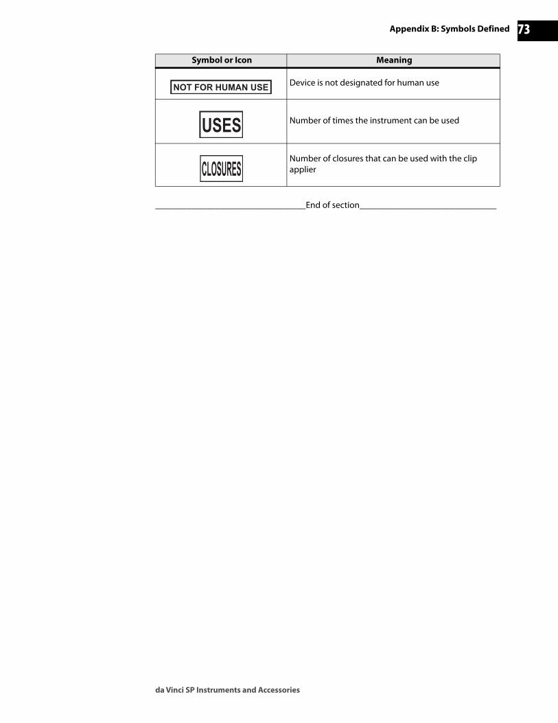
da Vinci SP Instruments and Accessories
Appendix B: Symbols Defined 73D
RA
FT/P
RE-
REL
EASE
/CO
NFI
DEN
TIA
L 12
/5/1
9
_________________________________End of section______________________________
Device is not designated for human use
Number of times the instrument can be used
Number of closures that can be used with the clip applier
Symbol or Icon Meaning

Appendix C: Natural Rubber Latex
da Vinci SP Instruments and Accessories
74D
RA
FT/P
RE-
REL
EASE
/CO
NFI
DEN
TIA
L12
/5/1
9
C Appendix C: Natural Rubber Latex
For the following Intuitive Surgical products containing elastomeric/pliable parts and referenced in this manual, materials that are intended to contact users or patients during normal use and handling are not made with natural rubber latex:
• EndoWrist SP Camera (PN 430060)
• MCS Tip and installation tool (PN 430035)
• Cautery Hook Tip, 5 mm (PN 400156)
• Cautery Spatula Tip, 5 mm (PN 400160)
• EntryGuide Kit C.6.6.6, 25 mm x 100 mm (PN 430022)
• EnergyShield Monopolar Cautery Cord (PN 430068)
• Bipolar Cautery Cord (PN 470384)
• Instrument Sheath (PN 430012)
• Camera Sheath (PN 430020)
_______________________________End of section_______________________________

da Vinci SP Instruments and Accessories
Appendix D: Intended Use Statements 75D
RA
FT/P
RE-
REL
EASE
/CO
NFI
DEN
TIA
L 12
/5/1
9
D Appendix D: Intended Use Statements
The following intended use statements apply to the da Vinci SP instruments and accessories. For information on specific indications for use and representative uses of the da Vinci SP Surgical System, refer to the appropriate da Vinci SP supplement.
Product Part Number Intended Use
EndoWrist SP Camera, 0° 430060The EndoWrist SP Camera, 0° is intended to provide stereoscopic visualization of tissue and instruments when performing procedures with the da Vinci SP System.
Needle Driver 430006The Needle Driver is intended to be used with the da Vinci SP System to drive needles and tie suture.
Round Tooth Retractor 430002The Round Tooth Retractor is intended to be used with the da Vinci SP System for retracting, grasping and manipulating tissues.
Cadiere Forceps 430009The Cadiere Forceps is intended to be used with the da Vinci SP System for dissecting, grasping, manipulating, and retracting tissues.
Medium-Large Clip Applier
430005
The Medium-Large Clip Applier is intended to be used with the da Vinci SP System for the application of Weck® Hem-o-lok® Medium-Large Polymer Ligating Clips for ligation of vessels and tissue bundles ranging in size from 3 - 10 mm in diameter.
Monopolar Curved Scissors and MCS Tip
430004430035
The Monopolar Curved Scissors with MCS Tip is intended to be used with the da Vinci SP System for manipulating, cutting, and dissecting tissue, coagulating and transecting tissue using monopolar electrosurgical energy, and cutting suture. The MCS Tip is also intended to provide electrical insulation over a section of the Monopolar Curved Scissors instrument so that RF energy is only available at the scissor blades.
Monopolar Cautery Instrument and Monopolar Cautery Tips
430007400156400160
The Monopolar Cautery Instrument with the 5 mm Cautery Hook Tip or 5 mm Cautery Spatula Tip is intended to be used with the da Vinci SP System for manipulating and dissecting tissue and coagulating and transecting tissue using monopolar electrosurgical energy.
Bipolar Instruments430010430011
The Maryland Bipolar Forceps and Fenestrated Bipolar Forceps are intended to be used with the da Vinci SP System for dissecting, grasping, manipulating, retracting, and coagulating tissues and vessels.
Bipolar Cautery Cord 470384
The Bipolar Cautery Cord is intended for connecting bipolar electrosurgical instruments to an electrosurgical generator to provide transmission of high frequency current from the electrosurgical generator to the surgical instrument.
EnergyShield Monopolar Cautery Cord
430068The EnergyShield Monopolar Cautery Cord is intended to conduct high frequency current from the electrosurgical generator and EnergyShield Monitor to a da Vinci shielded monopolar instrument.
SP Cannula, SP Obturator, and EntryGuide Kit
430036430016430022
The SP Cannula, SP Obturator, and EntryGuide Kit are intended to establish a port of entry for EndoWrist SP instruments, EndoWrist SP cameras, and compatible accessories.

Appendix D: Intended Use Statements
da Vinci SP Instruments and Accessories
76D
RA
FT/P
RE-
REL
EASE
/CO
NFI
DEN
TIA
L12
/5/1
9
_________________________________End of section______________________________
Instrument Sheath 430012
The Instrument Sheath is intended to be used with the EndoWrist SP surgical instruments to reduce ingress of biological material into the instrument, allow smooth insertion and retraction through the Entry Guide, and provide electrical insulation over the shaft and joints of the EndoWrist SP surgical instruments to reduce the likelihood of unintended electrosurgical energy delivery.
Camera Sheath 430020
The Camera Sheath is intended to be used with the EndoWrist SP Camera to reduce ingress of biological material into the camera, reduce component surface exposure, and allow smooth insertion and retraction through the Entry Guide.
Instrument Arm Drape 430013The Instrument Arm Drape is intended to be used with the da Vinci SP Patient Cart as a sterile barrier during clinical procedures.
Product Part Number Intended Use

da Vinci SP Instruments and Accessories
Appendix E: Sterilization Methods 77D
RA
FT/P
RE-
REL
EASE
/CO
NFI
DEN
TIA
L 12
/5/1
9
E Appendix E: Sterilization Methods
This table describes sterilization methods used for single-use Intuitive Surgical products referenced in this manual.
_________________________________End______________________________
Name Part Number MethodCamera Sheath 430020 Ethylene Oxide
Instrument Sheath 430012 Ethylene Oxide
MCS Tip 430035 Ethylene Oxide
Cautery Hook Tip, 5 mm 400156 Ethylene Oxide
Cautery Spatula Tip, 5 mm 400160 Ethylene Oxide
EntryGuide Kit C.6.6.6, 25 mm x 100 mm 430022 Gamma Irradiation
Instrument Arm Drape 430013 Ethylene Oxide