Embed Size (px)
Citation preview
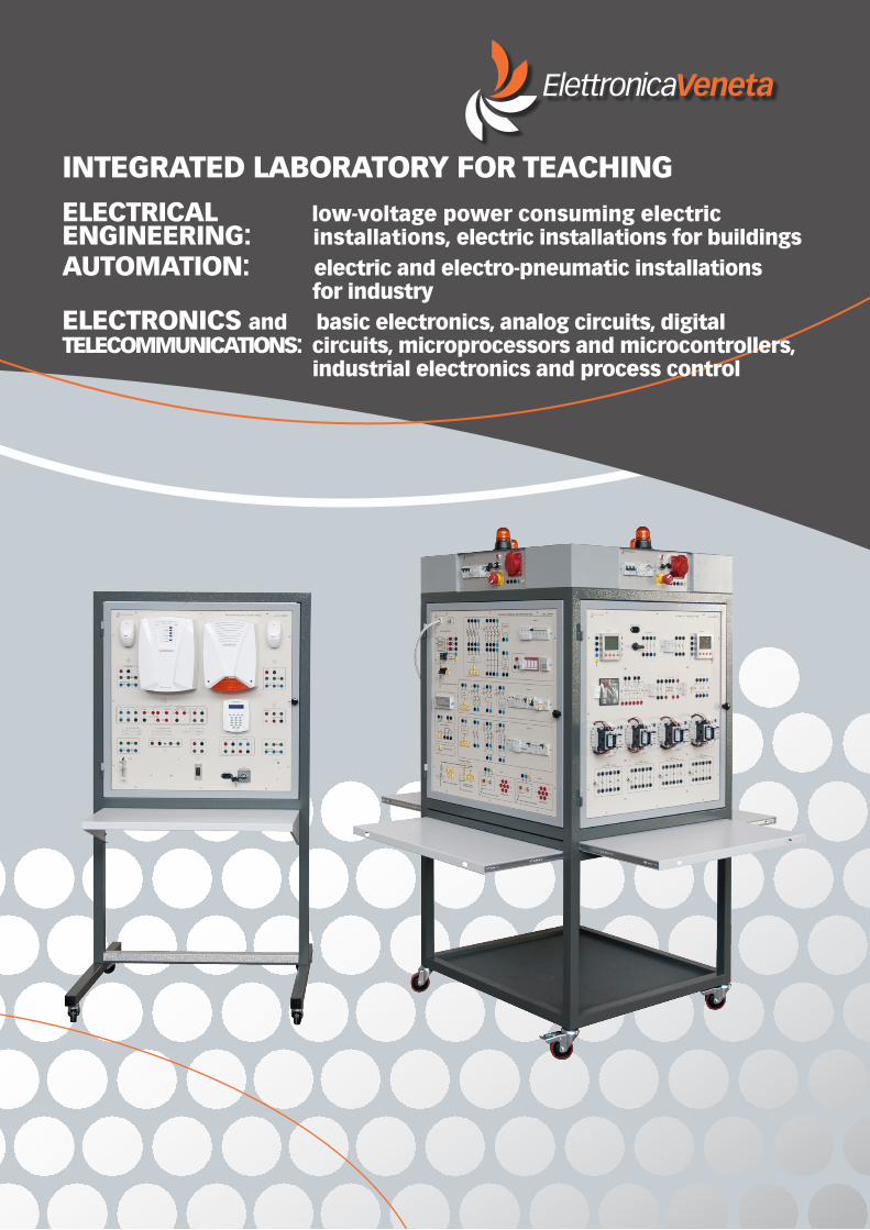
INTEGRATED LABORATORY FOR TEACHINGELECTRICAL low-voltage power consuming electricENGINEERING: installations, electric installations for buildingsAUTOMATION: electric and electro-pneumatic installations for industryELECTRONICS and basic electronics, analog circuits, digitalTELECOMMUNICATIONS: circuits, microprocessors and microcontrollers, industrial electronics and process control

INDEXINTEGRATED LABORATORY FOR TEACHING
WHEELED STRUCTURE Mod. LII-S/EV 4 FLOOR STANDING DISPLAY RACK Mod. LII-T/EV 5
VERTICAL BENCH WITH FOUR WORKSTATIONS Mod. 397-4/EV 7
IND
EX
DISTRIBUTION SYSTEMS AND PROTECTION DEVICES Mod. LII-SD1/EV 9
PANEL OF LIGHTING INSTALLATIONS AND SOCKETS Mod. LII-CB1/EV 11
PANEL OF ELECTRIC SIGNALLING SYSTEMS Mod. LII-CB2/EV 13
PANEL OF ELECTRONICALLY CONTROLLED INSTALLATIONS Mod. LII-CB3/EV 15
PANEL OF PIERCED METAL SHEET Mod. 397-PLF/EV 35
KIT FOR INDUSTRIAL INSTALLATIONS Mod. MI-P/EV 35
KIT FOR ELECTRO-PNEUMATIC SYSTEMS Mod. ME/EV 36
PANEL OF INNOVATIVE KNX BUS SYSTEMS Mod. LII-CD1/EV 17
PANEL OF BUS TELEPHONE AND VIDEO INTERPHONE SYSTEMS Mod. LII-CD3/EV 19
PANEL OF ANTI THEFT SYSTEMS Mod. LII-CD5/EV 21
PANEL OF FIRE DETECTING SYSTEMS Mod. LII-CD6/EV 23
PANEL WITH FLUSH-MOUNTED BRANCH EXCHANGE AND BOXES Mod. LII-PSC/EV 38
PANEL WITH FLUSH-MOUNTED BOXES Mod. LII-PSI/EV 38
KIT FOR SWITCHBOARDS OF LIVING UNIT Mod. MIS-Q/EV 39
KITS FOR LIGHTING INSTALLATIONS Mod. MIS-I/EV 40
KIT FOR SIGNALLING SYSTEMS Mod. MIS-S/EV 41
KIT FOR INTERPHONE SYSTEMS Mod. MIS-C/EV 41
PANEL OF TESTING IN ELECTRONICS AND TELECOMMUNICATIONS Mod. LII-SET/EV 43
PANEL FOR AUTOMATION OF WIRED INDUSTRIAL INSTALLATIONS Mod. LII-AI1/EV 25
PANEL OF ELECTRONICALLY CONTROLLED INDUSTRIAL INSTALLATIONS Mod. LII-AI2/EV 27
PANEL OF AUTOMATIC POWER FACTOR CORRECTION SYSTEMS Mod. LII-AI3/EV 29
PANEL OF ELECTRO-PNEUMATIC AUTOMATION SYSTEMS Mod. LII-AI4/EV 31
PANEL OF DC MOTOR STARTING AND CONTROL SYSTEMS Mod. LII-AI5/EV 33
GENERAL INTRODUCTION 3
Note: The catalog is constantly updated. Please send any suggestion you have to [email protected]. We would also like to remind you that, due to the continuous technological upgrades, the described products may be subjected to design and/or technical modifications. Nevertheless, we guarantee that the educational content of our equipment remains unchanged.
ELE
CT
RIC
AL
EN
GIN
EE
RIN
G
3ELETTRONICA VENETA S.P.A. - 31045 Motta di Livenza (TV) Italy - Via Postumia 16 - Tel. +39 0422 765 802 - Fax +39 0422 861 901 - E-mail: [email protected]
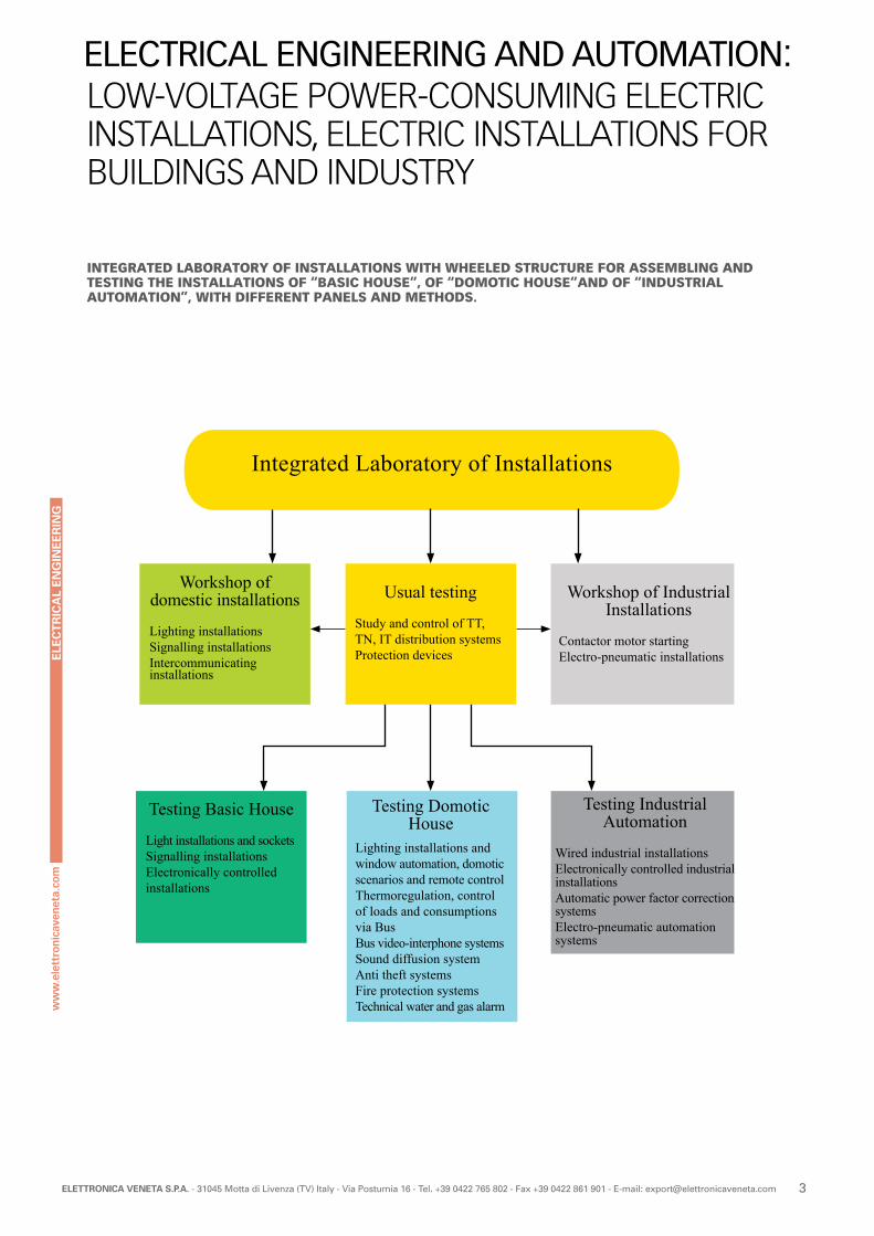
Integrated Laboratory of Installations
Workshop of domestic installations
Lighting installationsSignalling installationsIntercommunicating installations
Testing Basic House
Light installations and socketsSignalling installationsElectronically controlled installations
Usual testing
Study and control of TT, TN, IT distribution systemsProtection devices
Testing Domotic House
Lighting installations and window automation, domotic scenarios and remote controlThermoregulation, control of loads and consumptions via BusBus video-interphone systems Sound diffusion systemAnti theft systemsFire protection systemsTechnical water and gas alarm
Workshop of Industrial Installations
Contactor motor startingElectro-pneumatic installations
Testing Industrial Automation
Wired industrial installationsElectronically controlled industrial installationsAutomatic power factor correction systemsElectro-pneumatic automation systems
LOW-VOLTAGE POWER-CONSUMING ELECTRIC INSTALLATIONS, ELECTRIC INSTALLATIONS FOR BUILDINGS AND INDUSTRY
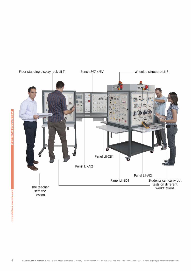
INTEGRATED LABORATORY OF INSTALLATIONS WITH WHEELED STRUCTURE FOR ASSEMBLING AND TESTING THE INSTALLATIONS OF “BASIC HOUSE”, OF “DOMOTIC HOUSE”AND OF “INDUSTRIAL AUTOMATION”, WITH DIFFERENT PANELS AND METHODS.
ELECTRICAL ENGINEERING AND AUTOMATION:
ELE
CT
RIC
AL
EN
GIN
EE
RIN
G
4 ELETTRONICA VENETA S.P.A. - 31045 Motta di Livenza (TV) Italy - Via Postumia 16 - Tel. +39 0422 765 802 - Fax +39 0422 861 901 - E-mail: [email protected]
The teacher sets the lesson
Bench 397-4/EV
Panel LII-AI3
Panel LII-SD1
Panel LII-AI2
Panel LII-CB1
Wheeled structure LII-SFloor standing display rack LII-T
Students can carry out tests on different
workstations
ELE
CT
RIC
AL
EN
GIN
EE
RIN
G
5ELETTRONICA VENETA S.P.A. - 31045 Motta di Livenza (TV) Italy - Via Postumia 16 - Tel. +39 0422 765 802 - Fax +39 0422 861 901 - E-mail: [email protected]
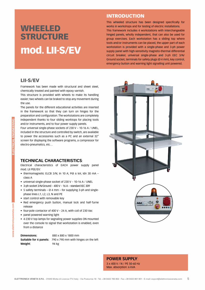
INTRODUCTIONThis wheeled structure has been designed specifically for
works in workshops and for testing of electric installations.
This framework includes 4 workstations with interchangeable
hinged panels, wholly independent, that can also be used for
group exercises. Each workstation has a sliding top where
tools and/or instruments can be placed, the upper part of each
workstation is provided with a single-phase and 3-ph power
supply panel with high-sensitivity magneto-thermal differential
circuit breaker, universal single-phase and 3-ph EEC 3/N/
Ground socket, terminals for safety plugs (Ø 4 mm), key control,
emergency button and warning light signalling unit powered.
WHEELED STRUCTURE
mod. LII-S/EV
LII-S/EVFramework has been made with structural and sheet steel,
chemically treated and painted with epoxy varnish.
This structure is provided with wheels to make its handling
easier; two wheels can be braked to stop any movement during
the use.
The panels for the different educational activities are inserted
in the framework so that they can turn on hinges for the
preparation and configuration. The workstations are completely
independent thanks to four sliding worktops for placing tools
and/or instruments, and to four power supply panels.
Four universal single-phase sockets of 230 V – 10-16 A / UNEL,
included in the structure and controlled by switch, are available
to power the accessories such as a PC and an external 32”
screen for displaying the software programs, a compressor for
electro-pneumatics, etc…
TECHNICAL CHARACTERISTICS:Electrical characteristics of EACH power supply panel
mod. LII PEE/EV:
• thermomagnetic ELCB 3/N; In 10 A; Pdi 6 kA; Idn 30 mA –
class A
• universal single-phase socket of 230 V – 10-16 A / UNEL
• 3-ph socket 3/N/Ground – 400 V – 16 A – standard IEC 309
• 5 safety terminals – Ø 4 mm – for supplying 3-ph and single-
phase lines L1, L2, L3, N and PE
• start control with removable key
• Red emergency push button, manual lock and half-Turne
release
• four-pole contactor of 400 V – 24 A, with coil of 230 Vac
• panel powered warning light
• 4·230 V top lamps for segnaling power supplies ON mounted
over the console to signal that workstation is enabled, even
from a distance
Dimensions: 880 x 880 x 1800 mm
Suitable for 4 panels: 790 x 790 mm with hinges on the left Weight: 94 kg
POWER SUPPLY:3 x 400 V / N / PE 50-60 HzMax. absorption: 6 kVA
ELE
CT
RIC
AL
EN
GIN
EE
RIN
G
6 ELETTRONICA VENETA S.P.A. - 31045 Motta di Livenza (TV) Italy - Via Postumia 16 - Tel. +39 0422 765 802 - Fax +39 0422 861 901 - E-mail: [email protected]
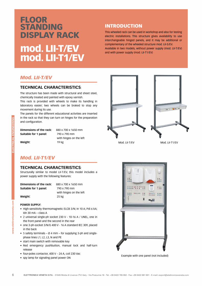
INTRODUCTIONThis wheeled rack can be used in workshop and also for testing
electric installations. This structure gives availability to use
interchangeable hinged panels, and it may be additional or
complementary of the wheeled structure mod. LII-S/EV.
Available in two models, without power supply (mod. LII-T/EV)
and with power supply (mod. LII-T1/EV)
FLOOR STANDING DISPLAY RACK
mod. LII-T/EVmod. LII-T1/EV
Mod. LII-T/EV
TECHNICAL CHARACTERISTICS:
The structure has been made with structural and sheet steel,
chemically treated and painted with epoxy varnish.
This rack is provided with wheels to make its handling in
laboratory easier; two wheels can be braked to stop any
movement during its use.
The panels for the different educational activities are inserted
in the rack so that they can turn on hinges for the preparation
and configuration.
Dimensions of the rack: 880 x 700 x 1650 mm
Suitable for 1 panel: 790 x 790 mm
with hinges on the left
Weight: 19 kg
Mod. LII-T1/EV
TECHNICAL CHARACTERISTICS:Structurally similar to model LII-T/EV, this model includes a
power supply with the following features:
Dimensions of the rack: 880 x 700 x 1650 mm
Suitable for 1 panel: 790 x 790 mm
with hinges on the left
Weight: 25 kg
POWER SUPPLY:• High-sensitivity thermomagnetic ELCB 3/N; In 10 A; Pdi 6 kA;
Idn 30 mA – class A
• 2 universal single-ph socket 230 V - 10-16 A / UNEL, one in
the front panel and the second in the rear
• one 3-ph-socket 3/N/G 400 V - 16 A standard IEC 309, placed
in the back
• 5 safety terminals – Ø 4 mm – for supplying 3-ph and single-
phase lines L1, L2, L3, N and PE
• start main switch with removable key
• Red emergency pushbutton, manual lock and half-turn
release
• four-poles contactor, 400 V – 24 A, coil 230 Vac
• spy lamp for signaling panel power ON
Mod. LII-T/EV Mod. LII-T1/EV
Example with one panel (not included)
ELE
CT
RIC
AL
EN
GIN
EE
RIN
G
7ELETTRONICA VENETA S.P.A. - 31045 Motta di Livenza (TV) Italy - Via Postumia 16 - Tel. +39 0422 765 802 - Fax +39 0422 861 901 - E-mail: [email protected]
VERTICAL BENCH WITH FOURWORKSTATIONS
Mod. 397-4/EV
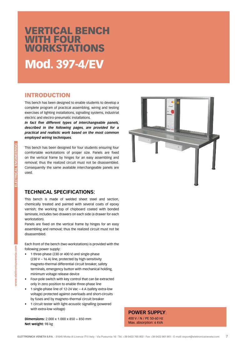
INTRODUCTIONThis bench has been designed to enable students to develop a
complete program of practical assembling, wiring and testing
exercises of lighting installations, signalling systems, industrial
electric and electro-pneumatic installations.
In fact five different types of interchangeable panels, described in the following pages, are provided for a practical and realistic work based on the most common employed wiring techniques.
This bench has been designed for four students ensuring four
comfortable workstations of proper size. Panels are fixed
on the vertical frame by hinges for an easy assembling and
removal; thus the realized circuit must not be disassembled.
Consequently the same available interchangeable panels are
used.
TECHNICAL SPECIFICATIONS:This bench is made of welded sheet steel and section,
chemically treated and painted with several coats of epoxy
varnish; the working top of chipboard coated with bonded
laminate, includes two drawers on each side (a drawer for each
workstation).
Panels are fixed on the vertical frame by hinges for an easy
assembling and removal; thus the realized circuit must not be
disassembled.
Each front of the bench (two workstations) is provided with the
following power supply:
• 1 three-phase (230 or 400 V) and single-phase
(230 V – 16 A) line, protected by high-sensitivity
magneto-thermal differential circuit breaker, safety
terminals, emergency button with mechanical holding,
minimum voltage release device
• Four-pole switch with key control that can be extracted
only in zero position to enable three-phase line
• 1 single-phase line of 12-24 Vac – 4 A (safety extra-low
voltage) protected against overloads and short-circuits
by fuses and by magneto-thermal circuit breaker
• 1 circuit tester with light-acoustic signalling (powered
with extra-low voltage)
Dimensions: 2.000 x 1.000 x 850 + 850 mm
Net weight: 98 kg
POWER SUPPLY:400 V / N / PE 50-60 HzMax. absorption: 6 kVA
ELE
CT
RIC
AL
EN
GIN
EE
RIN
G
8 ELETTRONICA VENETA S.P.A. - 31045 Motta di Livenza (TV) Italy - Via Postumia 16 - Tel. +39 0422 765 802 - Fax +39 0422 861 901 - E-mail: [email protected]
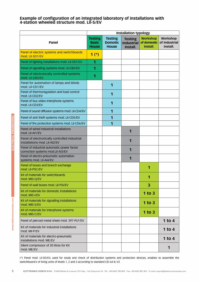
Installation typology
PanelTesting Basic House
Testing Domotic House
Testing Industrial
Install.
Workshop of domestic
install.
Workshop of Industrial
install.
Panel of electric systems and switchboardsmod. LII-SD1/EV 1 (*)
Panel of lighting installations mod. LII-CB1/EV 1Panel of signalling systems mod. LII-CB2/EV 1Panel of electronically controlled systems mod. LII-CB3/EV 1
Panel for automation of lamps and blinds mod. LII-CD1/EV 1
Panel of thermoregulation and load control mod. LII-CD2/EV 1
Panel of bus video-interphone systemsmod. LII-CD3/EV 1
Panel of sound diffusion systems mod. LII-CD4/EV 1Panel of anti theft systems mod. LII-CD5/EV 1Panel of fire protection systems mod. LII-CD6/EV 1Panel of wired industrial installationsmod. LII-AI1/EV 1
Panel of electronically controlled industrial installations mod. LII-AI2/EV 1
Panel of industrial automatic power factor correction systems mod.LII-AI3/EV 1Panel of electro-pneumatic automation systems mod. LII-AI4/EV 1
Panel of boxes and branch exchange mod. LII-PSC/EV 1
Kit of materials for switchboardsmod. MIS-Q/EV 1
Panel of wall boxes mod. LII-PSI/EV 3Kit of materials for domestic installationsmod. MIS-I/EV 1 to 3
Kit of materials for signalling installations mod. MIS-S/EV 1 to 3
Kit of materials for interphone systemsmod. MIS-C/EV 1 to 3
Panel of pierced metal sheet mod. 397-PLF/EV 1 to 4
Kit of materials for industrial installationsmod. MI-P/EV 1 to 4
Kit of materials for electro-pneumatic installations mod. ME/EV 1 to 4
Silent compressor of 20 litres for Kit mod. ME/EV 1
(*) Panel mod. LII-SD/EV, used for study and check of distribution systems and protection devices, enables to assemble the
switchboard/s of living units of levels 1, 2 and 3 according to standard CEI 64-8; V3
Example of configuration of an integrated laboratory of installations with 4-station wheeled structure mod. LII-S/EV
ELE
CT
RIC
AL
EN
GIN
EE
RIN
G
9ELETTRONICA VENETA S.P.A. - 31045 Motta di Livenza (TV) Italy - Via Postumia 16 - Tel. +39 0422 765 802 - Fax +39 0422 861 901 - E-mail: [email protected]
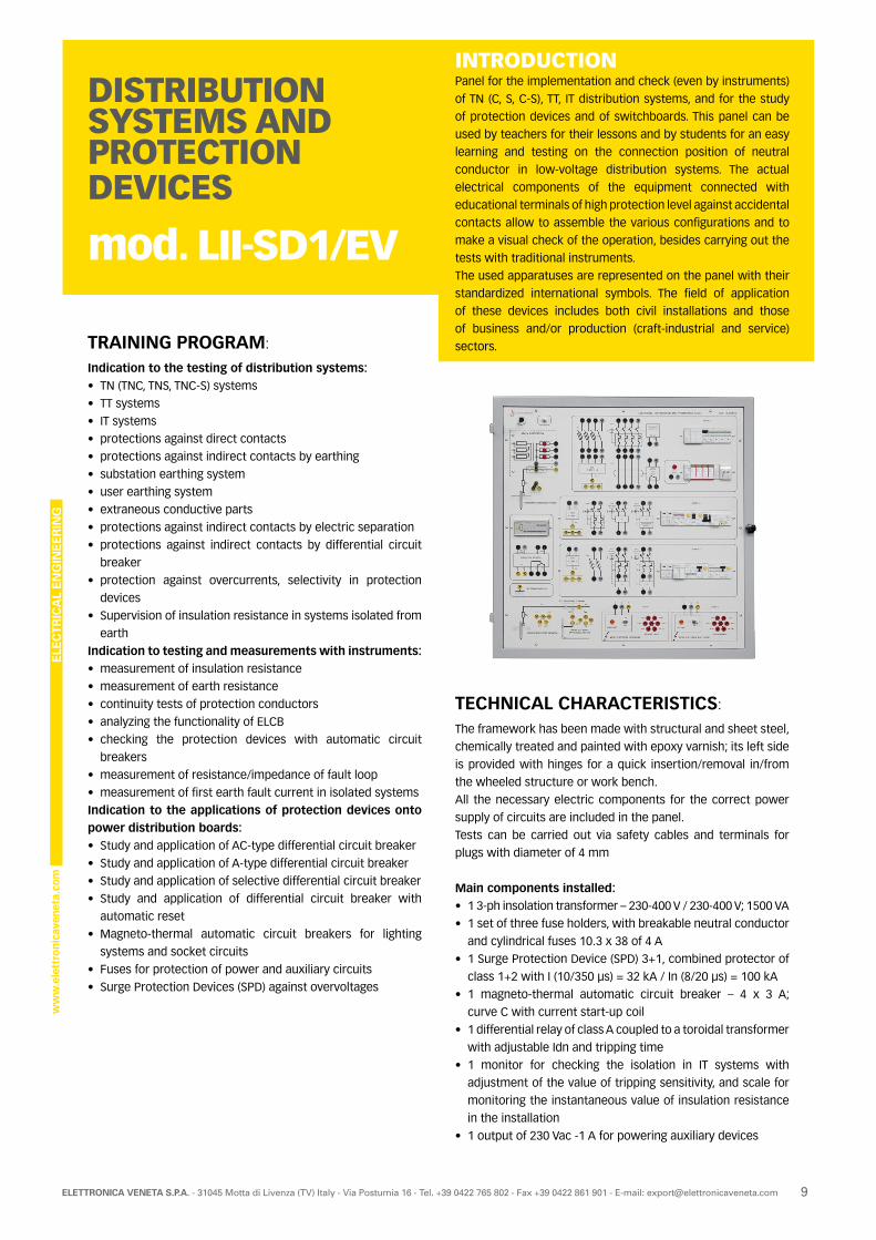
INTRODUCTIONPanel for the implementation and check (even by instruments)
of TN (C, S, C-S), TT, IT distribution systems, and for the study
of protection devices and of switchboards. This panel can be
used by teachers for their lessons and by students for an easy
learning and testing on the connection position of neutral
conductor in low-voltage distribution systems. The actual
electrical components of the equipment connected with
educational terminals of high protection level against accidental
contacts allow to assemble the various configurations and to
make a visual check of the operation, besides carrying out the
tests with traditional instruments.
The used apparatuses are represented on the panel with their
standardized international symbols. The field of application
of these devices includes both civil installations and those
of business and/or production (craft-industrial and service)
sectors.
DISTRIBUTION SYSTEMS AND PROTECTION DEVICES
mod. LII-SD1/EV
TRAINING PROGRAM:
Indication to the testing of distribution systems:• TN (TNC, TNS, TNC-S) systems
• TT systems
• IT systems
• protections against direct contacts
• protections against indirect contacts by earthing
• substation earthing system
• user earthing system
• extraneous conductive parts
• protections against indirect contacts by electric separation
• protections against indirect contacts by differential circuit
breaker
• protection against overcurrents, selectivity in protection
devices
• Supervision of insulation resistance in systems isolated from
earth
Indication to testing and measurements with instruments:• measurement of insulation resistance
• measurement of earth resistance
• continuity tests of protection conductors
• analyzing the functionality of ELCB
• checking the protection devices with automatic circuit
breakers
• measurement of resistance/impedance of fault loop
• measurement of first earth fault current in isolated systems
Indication to the applications of protection devices onto power distribution boards:• Study and application of AC-type differential circuit breaker
• Study and application of A-type differential circuit breaker
• Study and application of selective differential circuit breaker
• Study and application of differential circuit breaker with
automatic reset
• Magneto-thermal automatic circuit breakers for lighting
systems and socket circuits
• Fuses for protection of power and auxiliary circuits
• Surge Protection Devices (SPD) against overvoltages
TECHNICAL CHARACTERISTICS:
The framework has been made with structural and sheet steel,
chemically treated and painted with epoxy varnish; its left side
is provided with hinges for a quick insertion/removal in/from
the wheeled structure or work bench.
All the necessary electric components for the correct power
supply of circuits are included in the panel.
Tests can be carried out via safety cables and terminals for
plugs with diameter of 4 mm
Main components installed:• 1 3-ph insolation transformer – 230-400 V / 230-400 V; 1500 VA
• 1 set of three fuse holders, with breakable neutral conductor
and cylindrical fuses 10.3 x 38 of 4 A
• 1 Surge Protection Device (SPD) 3+1, combined protector of
class 1+2 with I (10/350 μs) = 32 kA / In (8/20 μs) = 100 kA
• 1 magneto-thermal automatic circuit breaker – 4 x 3 A;
curve C with current start-up coil
• 1 differential relay of class A coupled to a toroidal transformer
with adjustable Idn and tripping time
• 1 monitor for checking the isolation in IT systems with
adjustment of the value of tripping sensitivity, and scale for
monitoring the instantaneous value of insulation resistance
in the installation
• 1 output of 230 Vac -1 A for powering auxiliary devices
ELE
CT
RIC
AL
EN
GIN
EE
RIN
G
10 ELETTRONICA VENETA S.P.A. - 31045 Motta di Livenza (TV) Italy - Via Postumia 16 - Tel. +39 0422 765 802 - Fax +39 0422 861 901 - E-mail: [email protected]
• 1 three-pole lever selector for inserting two different values
of capacitance to earth in IT line
• 1 substation earthing system with resistances of 0.3 Ω, 1 Ω
• 1 user earthing system with resistances of 2 Ω, 20 Ω, 200 Ω, 2 kΩ
• 1 extraneous conductive part with resistances of 200 Ω, 1
kΩ, 5 kΩ
• 1 Surge Protection Device (SPD) against overvoltages 1+1,
protector of class 2, with Imax (8/20 μs) = 40 kA / In (8/20 μs)
= 20 kA
• 1 thermomagnetic automatic circuit breaker – 2 x 2 A; curve C
• 1 two-pole pure automatic differential circuit breaker of 25 A
/ 0.3 A, class AC, “S” selective
• 1 two-pole differential circuit breaker – Idn = 30 mA, of
A-type, with automatic reset
• 1 Surge Protection Device (SPD) against overvoltages 1+1 -
protector of class 3, with Imax (8/20 μs) = 10 kA / In (8/20 μs)
= 2.5 kA
• 1 breakable pair of fuse-holders with cylindrical fuses 10.3 x
38 of 2 A
• 1 thermomagnetic ELCB switch 2 x 1 A, curve C, Idn = 0.03 A,
class AC, with possibility of using the only magneto-thermal
switch without the differential part
• 1 magneto-thermal automatic differential switch 2 x 1 A,
curve C, Idn = 0.03 A, class A, with possibility of using the
only magneto-thermal switch without the differential part
• 1 simulator of power consuming device with sinusoidal earth
fault current; fault resistance of 50 kΩ, 15 kΩ, 5 kΩ, 1.5 kΩ,
500 Ω, bolted fault
• 1 simulator of power consuming device with sinusoidal or
unidirectional earth fault current; fault resistance of 50 kΩ,
15 kΩ, 5 kΩ, 1.5 kΩ, 500 Ω, bolted fault
Dimensions of working area: 730 x 730 mm
Dimensions of the panel: 790 x 790 x 200 mm
Weight: 38 kg
POWER SUPPLY:3 x 400 V / N / PE 50-60 Hz Max. absorption: 1500 VA
RECOMMENDED ACCESSORIES AND SOFTWARE:• Multi-function microprocessor instrument for electric testing
• Digital current probe for measuring rated and stray currents
with peak memory
• Digital autoranging multimeter
• Design, simulation and animation software for the study of
electrical engineering mod. SW-ELT/EV
ACCESSORIES OF THE EQUIPMENT:
• 3-ph power cord (of 2.5 m) with EEC socket and plug
• 20 jumpers with safety plugs (Ø 4 mm) for assembling
the various installation configurations
• Mixed set of 20 cables with safety plugs with diameter
of 4 mm
This panel can be used in different ways:
• it can be inserted in the wheeled structure of the integrated
laboratory of installations mod. LII-S/EV from which it is
powered;
• it can be inserted in the bench for exercises on installations
mod. 397-4/EV from which it is powered;
• it can be applied onto a wall like a blackboard; in this case, it
is powered via the nearest 3-ph socket.
THEORETICAL-EXPERIMENTAL HANDBOOKSPractical handbook of industrial installations.
ELE
CT
RIC
AL
EN
GIN
EE
RIN
G
11ELETTRONICA VENETA S.P.A. - 31045 Motta di Livenza (TV) Italy - Via Postumia 16 - Tel. +39 0422 765 802 - Fax +39 0422 861 901 - E-mail: [email protected]
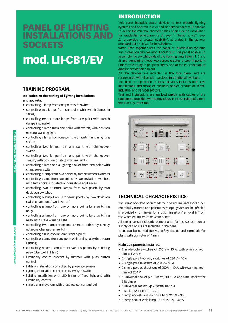
INTRODUCTIONThis panel includes actual devices to test electric lighting systems and sockets in civil and/or service sectors. It enables to define the minimal characteristics of an electric installation for residential environments of level 1: “basic house”, level 2: “properties of greater usability”, as stated in the general standard CEI 64-8; V3, for installations.When used together with the panel of “distribution systems and protection devices mod. LII-SD1/EV”, this panel enables to assemble the switchboards of the housing units (levels 1, 2 and 3) and combining these two panels creates a very important unit for the study of people’s safety and of the coordination of electric protection devices.All the devices are included in the fore panel and are represented with their standardized international symbols. The field of application of these devices includes both civil installations and those of business and/or production (craft-industrial and service) sectors.Test and installations are realized rapidly with cables of the equipment provided with safety plugs in the standard of 4 mm, without any other tool.
PANEL OF LIGHTING INSTALLATIONS AND SOCKETS
mod. LII-CB1/EV
TRAINING PROGRAM:
Indication to the testing of lighting installations and sockets:• controlling a lamp from one point with switch
• controlling two lamps from one point with switch (lamps in
series)
• controlling two or more lamps from one point with switch
(lamps in parallel)
• controlling a lamp from one point with switch, with position
or state warning light
• controlling a lamp from one point with switch, and a lighting
socket
• controlling two lamps from one point with changeover
switch
• controlling two lamps from one point with changeover
switch, with position or state warning lights
• controlling a lamp and a lighting socket from one point with
changeover switch
• controlling a lamp from two points by two deviation switches
• controlling a lamp from two points by two deviation switches,
with two sockets for electric household appliances
• controlling two or more lamps from two points by two
deviation switches
• controlling a lamp from three/four points by two deviation
switches and one/two inverter/s
• controlling a lamp from one or more points by a switching
relay
• controlling a lamp from one or more points by a switching
relay, with state warning light
• controlling two lamps from one or more points by a relay
acting as changeover switch
• controlling a fluorescent lamp from a point
• controlling a lamp from one point with timing relay (bathroom
lighting)
• controlling several lamps from various points by a timing
relay (stairwell lighting)
• luminosity control system by dimmer with push button
control
• lighting installation controlled by presence sensor
• lighting installation controlled by twilight switch
• lighting installation with LED lamps of fixed light and with
luminosity control
• simple alarm system with presence sensor and bell
TECHNICAL CHARACTERISTICS:
The framework has been made with structural and sheet steel,
chemically treated and painted with epoxy varnish; its left side
is provided with hinges for a quick insertion/removal in/from
the wheeled structure or work bench.
All the necessary electric components for the correct power
supply of circuits are included in the panel.
Tests can be carried out via safety cables and terminals for
plugs with diameter of 4 mm
Main components installed:• 2 single-pole switches of 250 V – 10 A, with warning neon
lamp of 230 V
• 2 single-pole two-way switches of 250 V – 10 A
• 2 single-pole inverters of 250 V – 10 A
• 2 single-pole pushbuttons of 250 V – 10 A, with warning neon
lamp of 230 V
• 1 universal socket (2p + earth) 10-16 A and Unel (socket for
S30 plugs)
• 1 universal socket (2p + earth) 10-16 A
• 1 socket (2p + earth) 10 A
• 2 lamp sockets with lamps E14 of 230 V – 3 W
• 1 lamp socket with lamp E27 of 230 V – 40 W
ELE
CT
RIC
AL
EN
GIN
EE
RIN
G
12 ELETTRONICA VENETA S.P.A. - 31045 Motta di Livenza (TV) Italy - Via Postumia 16 - Tel. +39 0422 765 802 - Fax +39 0422 861 901 - E-mail: [email protected]
• 1 ceiling lighting fixture with linear fluorescent lamp of 230 V –
18 W (one tube in white light and one tube in coloured light)
• 1 ballast for fluorescent lamp of 18 W, 1 universal starter 4-80 W
and 1 power factor correction capacitor of 5 μF – 250 V
• 1 buzzer of 230 V
• 1 cyclic (switch/changeover switch) relay, excitation of 230
Vac, contacts of 250 V – 10 A
• 1 timing relay for staircase lighting, excitation of 230 Vac,
contact of 250 V – 10 A
• 1 switch with IR movement sensor, adjustable twilight
threshold and delayed switching off, powered with 230 V,
output relay contact 230 V – 2 A with inductive loads
• 1 twilight switch with outdoor sensor, luminosity control,
power supply of 230 V, output of relay contact 230 V – 3 A
with inductive loads
• 1 button dimmer for resistive load and ferromagnetic
transformers of 230 V 60-500 W/VA
Dimensions of working area: 730 x 730 mm
Dimensions of the panel: 790 x 790 x 150 mm
Weight: 14 kg
POWER SUPPLY:Single-phase 230 V - 50-60 Hz - 1000 VA
ACCESSORIES OF THE EQUIPMENT:
• Set of 40 cables with safety plugs (Ø 4 mm)
THEORETICAL-EXPERIMENTAL HANDBOOKSPractical handbook of industrial installations.
This panel can be used in different ways:
• it can be inserted in the wheeled structure of the integrated
laboratory of installations mod. LII-S/EV from which it is
powered;
• it can be inserted in the bench for exercises on installations
mod. 397-4/EV from which it is powered;
• it can be inserted in one of the mobile floor-standing display
rack with work top for instruments:
- mod. LII-T/EV; in this case, it is powered via the nearest
3-ph socket;
- mod. LII-T1/EV, from which it is powered;
• it can be applied onto a wall like a blackboard; in this case, it
is powered via the nearest 3-ph socket.
ELE
CT
RIC
AL
EN
GIN
EE
RIN
G
13ELETTRONICA VENETA S.P.A. - 31045 Motta di Livenza (TV) Italy - Via Postumia 16 - Tel. +39 0422 765 802 - Fax +39 0422 861 901 - E-mail: [email protected]
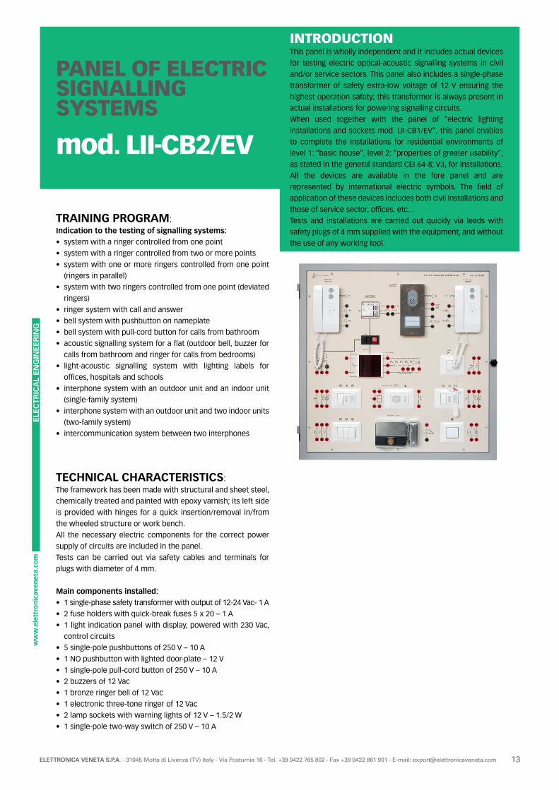
INTRODUCTIONThis panel is wholly independent and it includes actual devices
for testing electric optical-acoustic signalling systems in civil
and/or service sectors. This panel also includes a single-phase
transformer of safety extra-low voltage of 12 V ensuring the
highest operation safety; this transformer is always present in
actual installations for powering signalling circuits.
When used together with the panel of “electric lighting
installations and sockets mod. LII-CB1/EV”, this panel enables
to complete the installations for residential environments of
level 1: “basic house”, level 2: “properties of greater usability”,
as stated in the general standard CEI 64-8; V3, for installations.
All the devices are available in the fore panel and are
represented by international electric symbols. The field of
application of these devices includes both civil installations and
those of service sector, offices, etc...
Tests and installations are carried out quickly via leads with
safety plugs of 4 mm supplied with the equipment, and without
the use of any working tool.
PANEL OF ELECTRIC SIGNALLING SYSTEMS
mod. LII-CB2/EV
TRAINING PROGRAM:Indication to the testing of signalling systems:• system with a ringer controlled from one point
• system with a ringer controlled from two or more points
• system with one or more ringers controlled from one point
(ringers in parallel)
• system with two ringers controlled from one point (deviated
ringers)
• ringer system with call and answer
• bell system with pushbutton on nameplate
• bell system with pull-cord button for calls from bathroom
• acoustic signalling system for a flat (outdoor bell, buzzer for
calls from bathroom and ringer for calls from bedrooms)
• light-acoustic signalling system with lighting labels for
offices, hospitals and schools
• interphone system with an outdoor unit and an indoor unit
(single-family system)
• interphone system with an outdoor unit and two indoor units
(two-family system)
• intercommunication system between two interphones
TECHNICAL CHARACTERISTICS:The framework has been made with structural and sheet steel,
chemically treated and painted with epoxy varnish; its left side
is provided with hinges for a quick insertion/removal in/from
the wheeled structure or work bench.
All the necessary electric components for the correct power
supply of circuits are included in the panel.
Tests can be carried out via safety cables and terminals for
plugs with diameter of 4 mm.
Main components installed:• 1 single-phase safety transformer with output of 12-24 Vac- 1 A
• 2 fuse holders with quick-break fuses 5 x 20 – 1 A
• 1 light indication panel with display, powered with 230 Vac,
control circuits
• 5 single-pole pushbuttons of 250 V – 10 A
• 1 NO pushbutton with lighted door-plate – 12 V
• 1 single-pole pull-cord button of 250 V – 10 A
• 2 buzzers of 12 Vac
• 1 bronze ringer bell of 12 Vac
• 1 electronic three-tone ringer of 12 Vac
• 2 lamp sockets with warning lights of 12 V – 1.5/2 W
• 1 single-pole two-way switch of 250 V – 10 A
ELE
CT
RIC
AL
EN
GIN
EE
RIN
G
14 ELETTRONICA VENETA S.P.A. - 31045 Motta di Livenza (TV) Italy - Via Postumia 16 - Tel. +39 0422 765 802 - Fax +39 0422 861 901 - E-mail: [email protected]
POWER SUPPLY:Single-phase 230 V - 50-60 Hz - 100 VA
ACCESSORIES OF THE EQUIPMENT:• Set of 27 cables with safety plugs (Ø 4 mm)
• Set of 2 cables with safety plugs (Ø 2 mm)
THEORETICAL-EXPERIMENTAL HANDBOOKSPractical handbook of industrial installations.
This panel can be used in different ways:
• it can be inserted in the wheeled structure of the integrated
laboratory of installations mod. LII-S/EV from which it is
powered;
• it can be inserted in the bench for exercises on installations
mod. 397-4/EV from which it is powered;
• it can be inserted in one of the mobile floor-standing display
rack with work top for instruments:
- mod. LII-T/EV; in this case, it is powered via the nearest
socket;
- mod. LII-T1/EV, from which it is powered;
• it can be applied onto a wall like a blackboard; in this case, it
is powered via the nearest single-phase socket.
• 1 electric lock with excitation of 12 Vac and support for
showing the door opening
• 1 outdoor unit of interphone system with two-button door
plate
• 2 interphones provided with intercommunication and door
opening button
• 1 power supply unit for interphones with output of 230 Vac
• 1 power plug of board-type, 2P + Ground
• 1 cable of 0.5 mm² with German/French plug
Dimensions of working area: 730 x 730 mm
Dimensions of the panel: 790 x 790 x 150 mm
Weight: 16 kg
REMARK:Testing is carried out at safety extra-low voltage of 12 Vac output by the transformer included in the panel.
ELE
CT
RIC
AL
EN
GIN
EE
RIN
G
15ELETTRONICA VENETA S.P.A. - 31045 Motta di Livenza (TV) Italy - Via Postumia 16 - Tel. +39 0422 765 802 - Fax +39 0422 861 901 - E-mail: [email protected]
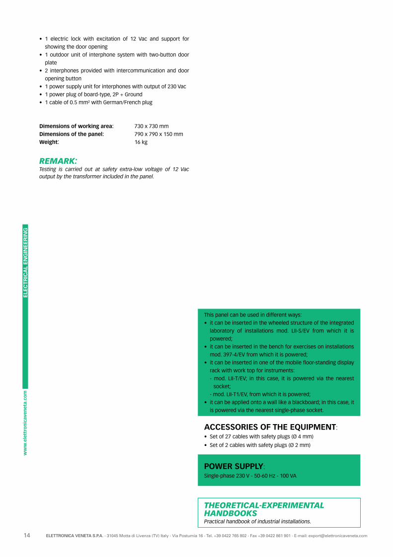
INTRODUCTIONThis independent panel is designed to assemble installations
with electronic devices for improving the building safety
and comfort (home automation). The systems that can be
assembled on this panel include dimmers for luminosity
control of fluorescent lamps, hour programmers, emergency
lighting with self-powered lamps, accent lighting with RGB-
coloured LED lamps, CO and gas leak detectors, thermostat
and chronothermostat for room temperature control, remote
enabling device via telephone line.
When used together with the panel of “electric lighting
installations and sockets mod. LII-CB1/EV”, this panel enables
to complete the installations for residential environments of
level 1: “basic house”, level 2: “properties of greater usability”,
as stated in the general standard CEI 64-8; V3, for installations.
All the devices are available in the fore panel and are
represented by international electric symbols. The field of
application of these devices includes both civil installations and
those of service sector, offices, etc...
Tests and installations are carried out quickly via leads with
safety plugs of 4 mm supplied with the equipment, and without
the use of any working tool.
PANEL OF ELECTRONICALLY CONTROLLED INSTALLATIONS
mod. LII-CB3/EV
TRAINING PROGRAM:Indication to the testing of systems for improving comfort and safety in houses:• Lighting installations with LED lamps of adjustable coloured
light for accent lighting
• Luminosity control systems with dimmer for fluorescent
lamps
• Luminosity control systems with dimmer for traditional
lamps and selection of different operating modes
• Installations with power consuming devices (lamps, electric
loads, actuators) controlled by hour programmer
• Installations with power consuming devices (lamps, electric
loads, actuators) controlled by telephone interface
• Lighting installations with emergency lamp; automatic
switching on; manual switching off
• Room temperature control system by electromechanical
thermostat
• Room temperature control system by programmable
chronothermostat
• Alarm system with gas leak detector and normally open
solenoid valve – manual reset
• Alarm system with CO detector
TECHNICAL CHARACTERISTICS:The framework has been made with structural and sheet steel,
chemically treated and painted with epoxy varnish; its left side
is provided with hinges for a quick insertion/removal in/from
the wheeled structure or work bench.
All the necessary electric components for the correct power
supply of circuits are included in the panel.
Tests can be carried out via safety cables and terminals for
plugs with diameter of 4 mm.
Main components installed:• 3 RGB LED lamps of 3 W – 350 mA
• 1 electronic dimmable power supply for LED lamp of 350 mA;
input of 220-240 Vac 50-60 Hz
• 1 electronic dimmable ballast QT-T/E of 18 W
• 1 lamp socket G24Q-2 and compact fluorescent lamp DULUX
D/E 18 W/830
• 1 controller of 1-10 Vdc for electronic dimmable ballasts
• 1 double (hour/week) digital switch, with automatic change
of summer time, power supply of 230 V 50-60 Hz, 2 outputs
relay contacts 230 V – 2 A with inductive loads
ELE
CT
RIC
AL
EN
GIN
EE
RIN
G
16 ELETTRONICA VENETA S.P.A. - 31045 Motta di Livenza (TV) Italy - Via Postumia 16 - Tel. +39 0422 765 802 - Fax +39 0422 861 901 - E-mail: [email protected]
POWER SUPPLY:Single-phase 230 V - 50-60 Hz - 100 VA
ACCESSORIES OF THE EQUIPMENT:
• Set of 25 cables with safety plugs (Ø 4 mm)
THEORETICAL-EXPERIMENTAL HANDBOOKSPractical handbook of industrial installations.
This panel can be used in different ways:
• it can be inserted in the wheeled structure of the integrated
laboratory of installations mod. LII-S/EV from which it is
powered;
• it can be inserted in the bench for exercises on installations
mod. 397-4/EV from which it is powered;
• it can be inserted in one of the mobile floor-standing display
rack with work top for instruments:
- mod. LII-T/EV; in this case, it is powered via the nearest
socket;
- mod. LII-T1/EV, from which it is powered;
• it can be applied onto a wall like a blackboard; in this case, it
is powered via the nearest single-phase socket.
• 1 multifunction dimmer with selector of different operating
modes, 230 V – 5…400 W/VA, controlled by pushbuttons
• 1 lamp socket E27 and lamp of 230 V – 40 W, with
silver-plated dome
• 1 single-pole two-way switch of 250 V – 10 A
• 2 single-pole pushbuttons of 250 V – 10 A
• 1 self-powered emergency light of 230 V 50-60 Hz, with
fluorescent lamp of 4 W
• 1 gas leak detector
• 1 solenoid valve for gas positive safety
• 1 CO detector
• 1 telephone actuator with 2 separate outputs, exchange
relay contacts, 250 V – 6 A
• 1 electromechanical room thermostat
• 1 room chronothermostat
Dimensions of working area: 730 x 730 mm
Dimensions of the panel: 790 x 790 x 150 mm
Weight: 16 kg
ELE
CT
RIC
AL
EN
GIN
EE
RIN
G
17ELETTRONICA VENETA S.P.A. - 31045 Motta di Livenza (TV) Italy - Via Postumia 16 - Tel. +39 0422 765 802 - Fax +39 0422 861 901 - E-mail: [email protected]
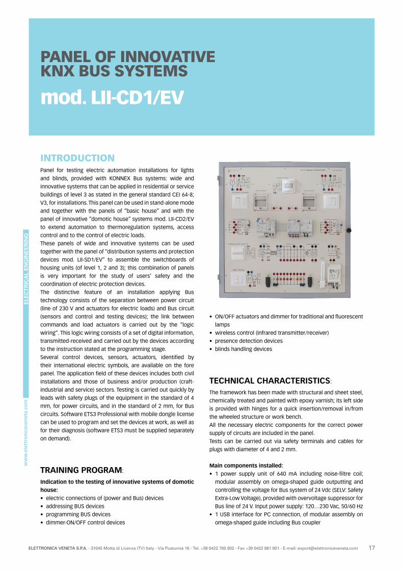
INTRODUCTIONPanel for testing electric automation installations for lights
and blinds, provided with KONNEX Bus systems: wide and
innovative systems that can be applied in residential or service
buildings of level 3 as stated in the general standard CEI 64-8;
V3, for installations. This panel can be used in stand-alone mode
and together with the panels of “basic house” and with the
panel of innovative “domotic house” systems mod. LII-CD2/EV
to extend automation to thermoregulation systems, access
control and to the control of electric loads.
These panels of wide and innovative systems can be used
together with the panel of “distribution systems and protection
devices mod. LII-SD1/EV” to assemble the switchboards of
housing units (of level 1, 2 and 3); this combination of panels
is very important for the study of users’ safety and the
coordination of electric protection devices.
The distinctive feature of an installation applying Bus
technology consists of the separation between power circuit
(line of 230 V and actuators for electric loads) and Bus circuit
(sensors and control and testing devices); the link between
commands and load actuators is carried out by the “logic
wiring”. This logic wiring consists of a set of digital information,
transmitted-received and carried out by the devices according
to the instruction stated at the programming stage.
Several control devices, sensors, actuators, identified by
their international electric symbols, are available on the fore
panel. The application field of these devices includes both civil
installations and those of business and/or production (craft-
industrial and service) sectors. Testing is carried out quickly by
leads with safety plugs of the equipment in the standard of 4
mm, for power circuits, and in the standard of 2 mm, for Bus
circuits. Software ETS3 Professional with mobile dongle license
can be used to program and set the devices at work, as well as
for their diagnosis (software ETS3 must be supplied separately
on demand).
TRAINING PROGRAM:
Indication to the testing of innovative systems of domotic house:• electric connections of (power and Bus) devices
• addressing BUS devices
• programming BUS devices
• dimmer-ON/OFF control devices
PANEL OF INNOVATIVE KNX BUS SYSTEMS
mod. LII-CD1/EV
• ON/OFF actuators and dimmer for traditional and fluorescent
lamps
• wireless control (infrared transmitter/receiver)
• presence detection devices
• blinds handling devices
TECHNICAL CHARACTERISTICS:
The framework has been made with structural and sheet steel,
chemically treated and painted with epoxy varnish; its left side
is provided with hinges for a quick insertion/removal in/from
the wheeled structure or work bench.
All the necessary electric components for the correct power
supply of circuits are included in the panel.
Tests can be carried out via safety terminals and cables for
plugs with diameter of 4 and 2 mm.
Main components installed:• 1 power supply unit of 640 mA including noise-filtre coil;
modular assembly on omega-shaped guide outputting and
controlling the voltage for Bus system of 24 Vdc (SELV: Safety
Extra-Low Voltage), provided with overvoltage suppressor for
Bus line of 24 V. Input power supply: 120…230 Vac, 50/60 Hz
• 1 USB interface for PC connection, of modular assembly on
omega-shaped guide including Bus coupler
ELE
CT
RIC
AL
EN
GIN
EE
RIN
G
18 ELETTRONICA VENETA S.P.A. - 31045 Motta di Livenza (TV) Italy - Via Postumia 16 - Tel. +39 0422 765 802 - Fax +39 0422 861 901 - E-mail: [email protected]
POWER SUPPLY:• Single-phase 230 V - 50-60 Hz - 100 VA
RECOMMENDED ACCESSORIES AND SOFTWARE:
Original multi-language Design EIB Tool Software mod. ETS4
Professional edited by consortium Konnex.
This software enables to assign the specific functionality to
the installation, as well as the starting and diagnosis of BUS
devices; it is used with a personal computer (not included in the
equipment) connected with the BUS system via USB interface.
ACCESSORIES OF THE EQUIPMENT:
• Set of : 30 cables with safety plugs (Ø 4 mm), 20 cables with
safety plugs (Ø 2 mm)
THEORETICAL-EXPERIMENTAL HANDBOOKSPractical handbook of industrial installations.
This panel can be used in different ways:
• it can be inserted in the wheeled structure of the integrated
laboratory of installations mod. LII-S/EV from which it is
powered;
• it can be inserted in the bench for exercises on installations
mod. 397-4/EV from which it is powered;
• it can be inserted in one of the mobile floor-standing display
rack with work top for instruments:
- mod. LII-T/EV; in this case, it is powered via the nearest
3-ph socket;
- mod. LII-T1/EV, from which it is powered;
• it can be applied onto a wall like a blackboard; in this case, it
is powered via the nearest 3-ph socket.
• 1 8-channel binary output for controlling power consuming
devices or groups of power consuming devices separately,
with rated load of 230 V – 8 A; modular assembly on omega-
shaped guide including Bus coupler
• 2 actuator for motors of blinds including Bus coupler suitable
to be inserted in control boxes. Blind actuators are equipped
with a pair of buttons for activations
• 2 miniaturized blinds with 230 Vac motors for up-down
motion controlled by limit switches and two windows with
shutters that interact with the corresponding magnetic
contacts of anti theft system
• 1 scenario module: modular equipment suitable to store
up to 4 “scenarios”. Each scenario can contain up to 8
address groups (particular operating situations) and it can be
retrieved by external commands
• 1 dimmer actuator of 230 V – 20-250 VA for incandescent or
halogen lamps, including bus coupler. This dimmer actuator
is equipped with pair of buttons for various activations
• 1 flush-mounted passive infrared motion sensor including
coupler for the connection with Bus line
• 2 sets of 4 pushbuttons connected with two 4-channel Bus
couplers suitable to be inserted in control boxes. Channels
can also be used with external contacts to interface various
devices
• 1 flush-mounted IR decoder-receiver including Bus coupler.
This IR receiver is equipped with four pairs of buttons for
various activations, and with four LEDs of state indications
• 1 portable infrared (IR) transmitter of 4+4 channels
• 2 lamp sockets E10 with lamps of 230 V – 5-10 W for dimmer
activation
• 1 electronic dimmable ballast with compact fluorescent
lamp of 230 V – 18 W for dimmer activation
All modular devices are inserted on DIN guide provided with
data strip for Bus links. A part of this data strip is available for
the insertion of additional modular devices.
Dimensions of working area: 730 x 730 mm
Dimensions of the panel: 790 x 790 x 150 mm
Weight: 16 kg
REMARK:This panel is “open” to be integrated with new devices of home automation of KONNEX standard. Refer to panel mod. LIC-CD2/EV.

ELE
CT
RIC
AL
EN
GIN
EE
RIN
G
19ELETTRONICA VENETA S.P.A. - 31045 Motta di Livenza (TV) Italy - Via Postumia 16 - Tel. +39 0422 765 802 - Fax +39 0422 861 901 - E-mail: [email protected]
INTRODUCTIONThis panel is totally independent and it includes actual
devices for testing Bus telephone, video interphone and
video surveillance systems that can be applied in buildings
of residential and/or service sectors, of level 3, as stated in
the general standard CEI 64-8; V3, for installations.. Tests and
installations are carried out on the panel quickly via leads with
safety plugs of 2 mm supplied with the equipment, and without
the use of any working tool.
All the devices are available in the fore panel of insulating
material and are represented by international electric symbols.
The distinctive feature of a video interphone installation
applying Bus technology consists in using only two wires to
carry both interphone and video signal, suitably compressed,
in digital format.
PANEL OF BUS TELEPHONE AND VIDEO INTERPHONE SYSTEMS
mod. LII-CD3/EV
TRAINING PROGRAM:
Indication to the testing of bus telephone and video interphone systems:• electric connections of (power and Bus) devices
• 2-wire video interphone system with an outdoor audio-
video unit and an indoor video-interphone unit (single-family
system)
• 2-wire video interphone system with an outdoor audio-
video unit and two indoor video-interphone units (two-family
system)
• 2-wire video interphone system with a further camera for
video surveillance
• telephone indoor system with electronic branch exchange
for managing up to 8 extension telephones
• interaction between indoor video-interphone and telephone
systems
TECHNICAL CHARACTERISTICS:
The framework has been made with structural and sheet steel,
chemically treated and painted with epoxy varnish; its left side
is provided with hinges for a quick insertion/removal in/from
the wheeled structure or work bench.
All the necessary electric components for the correct power
supply of circuits are included in the panel.
Tests can be carried out via safety terminals and cables for
plugs with diameter of 2 mm and 4 mm.
Main components installed:• 1 self-protected electronic power supply unit for 2-wire
digital video interphone systems; power supply: 230 Vac
• 1 outdoor two-wire digital unit with ¼”-sensor colours CCD
camera, infrared lighting, two calling buttons and lighting
plate
• 1 warning light of 12 V for simulating electric lock
• 1 wall-type video interphone with colours screen for 2-wire
digital systems, including a lock opening button and button
for switching the screen on in automatic mode
• 1 video display: wall-type video interphone terminal with
colour screen of 3.5”, for two-wire digital systems, including
a lock opening button and button for switching the screen on
in automatic mode
• 1 distributor 4 outputs video for 2-wire digital systems
• 1 colour 1/3”-sensor CCD camera for interiors, for 2-wire
digital systems
ELE
CT
RIC
AL
EN
GIN
EE
RIN
G
20 ELETTRONICA VENETA S.P.A. - 31045 Motta di Livenza (TV) Italy - Via Postumia 16 - Tel. +39 0422 765 802 - Fax +39 0422 861 901 - E-mail: [email protected]
POWER SUPPLY:Single-phase 230 V - 50-60 Hz - 100 VA
ACCESSORIES OF THE EQUIPMENT:• Set of 6 two-pole cables for video-interphone systems
with safety plugs (Ø 2 mm)
• Set of 8 cables with safety plugs (Ø 4 mm)
THEORETICAL-EXPERIMENTAL HANDBOOKSPractical handbook of industrial installations.
This panel can be used in different ways:
• it can be inserted in the wheeled structure of the integrated
laboratory of installations mod. LII-S/EV from which it is
powered;
• it can be inserted in the bench for exercises on installations
mod. 397-4/EV from which it is powered;
• it can be inserted in one of the mobile floor-standing display
rack with work top for instruments:
- mod. LII-T/EV; in this case, it is powered via the nearest
socket;
- mod. LII-T1/EV, from which it is powered;
• it can be applied onto a wall like a blackboard; in this case, it
is powered via the nearest single-phase socket.
• 1 selector video for 4 input sources and 1 output
• 1 Private Automatic Branch eXchange (PABX) with 2 inputs of
exchange line and 8 outputs for extension telephones
• 1 interface between branch exchange (PABX) and 2-wire
video-interphone systems
• 1 network terminator with 10 jacks RJ 11 for quick
connections with/from the branch exchange
• 6 tabletop impulse/multi-frequency telephone sets including
lead RJ 11
• 1 panel-type, 2P power plug and cable 2 x 0.5 mm²
• 1 two-pole ON-OFF control lever switch
Dimensions of working area: 730 x 730 mm
Dimensions of the panel: 790 x 790 x 150 mm
Weight: 15 kg
ELE
CT
RIC
AL
EN
GIN
EE
RIN
G
21ELETTRONICA VENETA S.P.A. - 31045 Motta di Livenza (TV) Italy - Via Postumia 16 - Tel. +39 0422 765 802 - Fax +39 0422 861 901 - E-mail: [email protected]
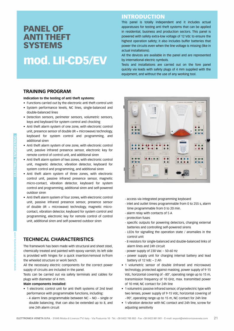
INTRODUCTIONThis panel is totally independent and it includes actual
apparatuses for testing anti theft systems that can be applied
in residential, business and production sectors. This panel is
powered with safety extra-low voltage of 12 Vdc to ensure the
highest operation safety; it also includes buffer batteries that
power the circuits even when the line voltage is missing (like in
actual installations).
All the devices are available in the panel and are represented
by international electric symbols.
Tests and installations are carried out on the fore panel
quickly via leads with safety plugs of 4 mm supplied with the
equipment, and without the use of any working tool.
PANEL OF ANTI THEFT SYSTEMS
mod. LII-CD5/EV
TRAINING PROGRAM:
Indication to the testing of anti theft systems:• Functions carried out by the electronic anti theft control unit
• System performance levels, NC lines, single-balanced and
double-balanced lines
• Detection sensors, perimeter sensors, volumetric sensors,
keys and keyboard for system control and chocking
• Anti theft alarm system of one zone, with electronic control
unit, presence sensor of double (IR + microwave) technology,
keyboard for system control and programming, and
additional siren
• Anti theft alarm system of one zone, with electronic control
unit, passive infrared presence sensor, electronic key for
remote control of control unit, and additional siren
• Anti theft alarm system of two zones, with electronic control
unit, magnetic detector, vibration detector, keyboard for
system control and programming, and additional siren
• Anti theft alarm system of three zones, with electronic
control unit, passive infrared presence sensor, magnetic
micro-contact, vibration detector, keyboard for system
control and programming, additional siren and self-powered
outdoor siren
• Anti theft alarm system of four zones, with electronic control
unit, passive infrared presence sensor, presence sensor
of double (IR + microwave) technology, magnetic micro-
contact, vibration detector, keyboard for system control and
programming, electronic key for remote control of control
unit, additional siren and self-powered outdoor siren
TECHNICAL CHARACTERISTICS:
The framework has been made with structural and sheet steel,
chemically treated and painted with epoxy varnish; its left side
is provided with hinges for a quick insertion/removal in/from
the wheeled structure or work bench.
All the necessary electric components for the correct power
supply of circuits are included in the panel.
Tests can be carried out via safety terminals and cables for
plugs with diameter of 4 mm.
Main components installed:• 1 electronic control unit for anti theft systems of 2nd level
performance with programmable functions, including:
- 4 alarm lines programmable between NC – NO – single or
double balancing, that can also be extended up to 8, and
one 24h alarm circuit
- access via integrated programming keyboard
- inlet and outlet times programmable from 0 to 255 s, alarm
time programmable from 0 to 20 min.
- alarm relay with contacts of 5 A
- protection fuses
- specific outputs for powering detectors, charging external
batteries and controlling self-powered sirens
- LEDs for signalling the operation state / anomalies in the
control unit
- 8 resistors for single-balanced and double-balanced links of
alarm lines and 24h circuit
- power supply of 230 Vac – 50-60 Hz
- power supply unit for charging internal battery and lead
battery of 12 Vdc – 2 Ah
• 1 volumetric sensor of double (infrared and microwave)
technology, protected against masking, power supply of 9-15
Vdc, horizontal covering of ~80°, operating range up to 15 m,
transmission frequency of 10 GHz, max. transmitted power
of 10 mW, NC contact for 24h line
• 1 volumetric passive infrared sensor, of pyroelectric type with
two lenses, power supply of 9-15 Vdc, horizontal covering of
~90°, operating range up to 15 m, NC contact for 24h line
• 1 vibration detector with NC contact and 24h line, screw for
adjusting sensitivity
ELE
CT
RIC
AL
EN
GIN
EE
RIN
G
22 ELETTRONICA VENETA S.P.A. - 31045 Motta di Livenza (TV) Italy - Via Postumia 16 - Tel. +39 0422 765 802 - Fax +39 0422 861 901 - E-mail: [email protected]
POWER SUPPLY:Single-phase 230 V - 50-60 Hz - 50 VA
ACCESSORIES OF THE EQUIPMENT:
• Set of 35 cables with safety plugs (Ø 4 mm)
THEORETICAL-EXPERIMENTAL HANDBOOKSPractical handbook of industrial installations.
This panel can be used in different ways:
• it can be inserted in the wheeled structure of the integrated
laboratory of installations mod. LII-S/EV from which it is
powered;
• it can be inserted in the bench for exercises on installations
mod. 397-4/EV from which it is powered;
• it can be inserted in one of the mobile floor-standing display
rack with work top for instruments:
- mod. LII-T/EV; in this case, it is powered via the nearest
3-ph socket;
- mod. LII-T1/EV, from which it is powered;
• it can be applied onto a wall like a blackboard; in this case, it
is powered via the nearest 3-ph socket.
• 1 magnetic detector with NC contact 24h line
• 1 self-protected and self-powered outdoor electronic siren;
power supply of 13.8-14.1 Vdc; protection against tampering
(24h line); max. sound power at 1 m: 117 dB; frequency of
1600-2700 Hz; flashing frequency of 1 Hz; including lead
battery of 12 Vdc – 2 Ah
• 1 indoor two-tone siren, powered with 9-14 Vdc; max. sound
power at 1 m adjustable from 80 dB to 113 dB; frequency of
1600-2900 Hz; modulation frequency: 2-3 Hz
• 1 remote electronic key; functions: on / off / choking of
control unit; power supply of 12 Vdc; 3 state LEDs; reading of
keys without contact near the socket
• Remote keyboard for controlling and programming the
control unit, powered with 12 Vdc, with backlit Liquid-Crystal
Display (LCD), 3 state LEDs and 4 programmable LEDs for
other controls, input for 2 NC anti theft lines for connection
of local alarm devices
• 1 board-type power plug (2P + earth)
• 1 cable of 0.75 mm² with German/French plug
• 1 key switch for excluding batteries at the end of the class to
prevent them from running down completely
Dimensions of working area: 730 x 730 mm
Dimensions of the panel: 790 x 790 x 220 mm
Weight: 18 kg
REMARK:Testing is carried out at safety extra-low voltage of 12 Vdc
output by power supply unit and by batteries included in the
control unit and in the self-powered siren.
ELE
CT
RIC
AL
EN
GIN
EE
RIN
G
23ELETTRONICA VENETA S.P.A. - 31045 Motta di Livenza (TV) Italy - Via Postumia 16 - Tel. +39 0422 765 802 - Fax +39 0422 861 901 - E-mail: [email protected]
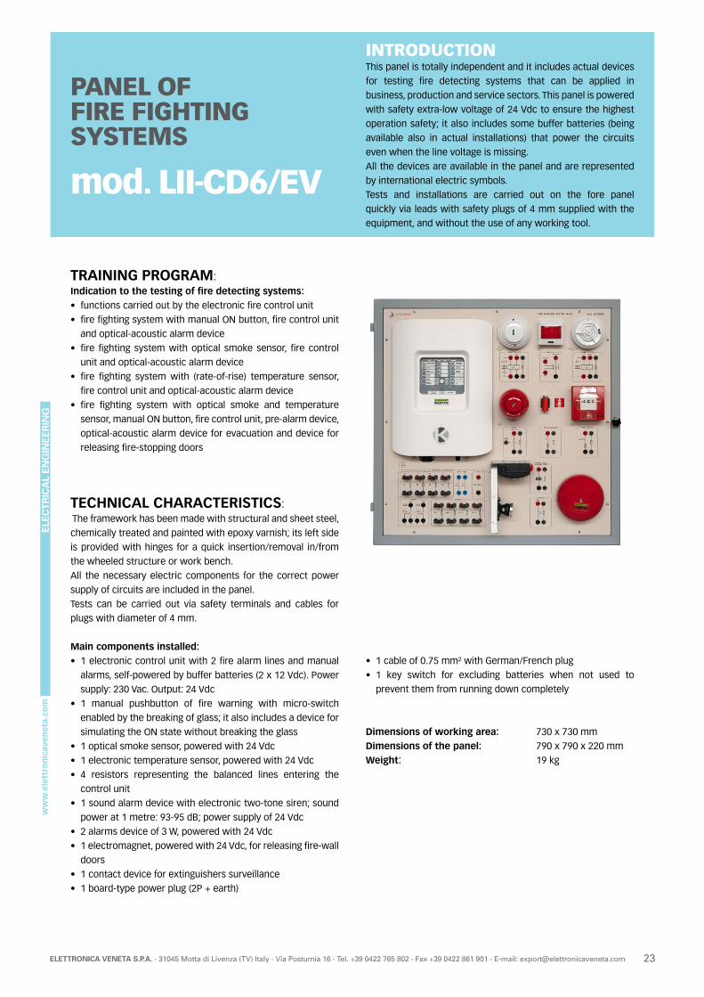
INTRODUCTIONThis panel is totally independent and it includes actual devices
for testing fire detecting systems that can be applied in
business, production and service sectors. This panel is powered
with safety extra-low voltage of 24 Vdc to ensure the highest
operation safety; it also includes some buffer batteries (being
available also in actual installations) that power the circuits
even when the line voltage is missing.
All the devices are available in the panel and are represented
by international electric symbols.
Tests and installations are carried out on the fore panel
quickly via leads with safety plugs of 4 mm supplied with the
equipment, and without the use of any working tool.
PANEL OF FIRE FIGHTING SYSTEMS
mod. LII-CD6/EV
TRAINING PROGRAM:Indication to the testing of fire detecting systems:• functions carried out by the electronic fire control unit
• fire fighting system with manual ON button, fire control unit
and optical-acoustic alarm device
• fire fighting system with optical smoke sensor, fire control
unit and optical-acoustic alarm device
• fire fighting system with (rate-of-rise) temperature sensor,
fire control unit and optical-acoustic alarm device
• fire fighting system with optical smoke and temperature
sensor, manual ON button, fire control unit, pre-alarm device,
optical-acoustic alarm device for evacuation and device for
releasing fire-stopping doors
TECHNICAL CHARACTERISTICS: The framework has been made with structural and sheet steel,
chemically treated and painted with epoxy varnish; its left side
is provided with hinges for a quick insertion/removal in/from
the wheeled structure or work bench.
All the necessary electric components for the correct power
supply of circuits are included in the panel.
Tests can be carried out via safety terminals and cables for
plugs with diameter of 4 mm.
Main components installed:• 1 electronic control unit with 2 fire alarm lines and manual
alarms, self-powered by buffer batteries (2 x 12 Vdc). Power
supply: 230 Vac. Output: 24 Vdc
• 1 manual pushbutton of fire warning with micro-switch
enabled by the breaking of glass; it also includes a device for
simulating the ON state without breaking the glass
• 1 optical smoke sensor, powered with 24 Vdc
• 1 electronic temperature sensor, powered with 24 Vdc
• 4 resistors representing the balanced lines entering the
control unit
• 1 sound alarm device with electronic two-tone siren; sound
power at 1 metre: 93-95 dB; power supply of 24 Vdc
• 2 alarms device of 3 W, powered with 24 Vdc
• 1 electromagnet, powered with 24 Vdc, for releasing fire-wall
doors
• 1 contact device for extinguishers surveillance
• 1 board-type power plug (2P + earth)
• 1 cable of 0.75 mm² with German/French plug
• 1 key switch for excluding batteries when not used to
prevent them from running down completely
Dimensions of working area: 730 x 730 mm
Dimensions of the panel: 790 x 790 x 220 mm
Weight: 19 kg
ELE
CT
RIC
AL
EN
GIN
EE
RIN
G
24 ELETTRONICA VENETA S.P.A. - 31045 Motta di Livenza (TV) Italy - Via Postumia 16 - Tel. +39 0422 765 802 - Fax +39 0422 861 901 - E-mail: [email protected]
POWER SUPPLY:Single-phase 230 V - 50-60 Hz - 50 VA
ACCESSORIES OF THE EQUIPMENT:
• Set of 20 cables with safety plugs (Ø 4 mm)
THEORETICAL-EXPERIMENTAL HANDBOOKSPractical handbook of industrial installations.
This panel can be used in different ways:
• it can be inserted in the wheeled structure of the integrated
laboratory of installations mod. LII-S/EV from which it is
powered;
• it can be inserted in the bench for exercises on installations
mod. 397-4/EV from which it is powered;
• it can be inserted in one of the mobile floor-standing display
rack with work top for instruments:
- mod. LII-T/EV; in this case, it is powered via the nearest
3-ph socket;
- mod. LII-T1/EV, from which it is powered;
• it can be applied onto a wall like a blackboard; in this case, it
is powered via the nearest 3-ph socket.
REMARK:Testing is carried out at safety extra-low voltage of 24 Vdc output by power supply unit and by batteries included in the control unit.
ELE
CT
RIC
AL
EN
GIN
EE
RIN
G
25ELETTRONICA VENETA S.P.A. - 31045 Motta di Livenza (TV) Italy - Via Postumia 16 - Tel. +39 0422 765 802 - Fax +39 0422 861 901 - E-mail: [email protected]
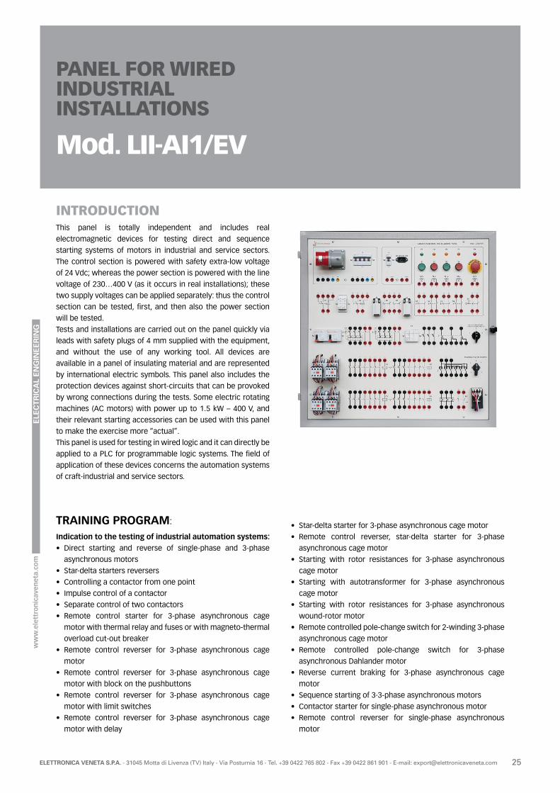
INTRODUCTIONThis panel is totally independent and includes real
electromagnetic devices for testing direct and sequence
starting systems of motors in industrial and service sectors.
The control section is powered with safety extra-low voltage
of 24 Vdc; whereas the power section is powered with the line
voltage of 230…400 V (as it occurs in real installations); these
two supply voltages can be applied separately: thus the control
section can be tested, first, and then also the power section
will be tested.
Tests and installations are carried out on the panel quickly via
leads with safety plugs of 4 mm supplied with the equipment,
and without the use of any working tool. All devices are
available in a panel of insulating material and are represented
by international electric symbols. This panel also includes the
protection devices against short-circuits that can be provoked
by wrong connections during the tests. Some electric rotating
machines (AC motors) with power up to 1.5 kW – 400 V, and
their relevant starting accessories can be used with this panel
to make the exercise more “actual”.
This panel is used for testing in wired logic and it can directly be
applied to a PLC for programmable logic systems. The field of
application of these devices concerns the automation systems
of craft-industrial and service sectors.
TRAINING PROGRAM:
Indication to the testing of industrial automation systems:• Direct starting and reverse of single-phase and 3-phase
asynchronous motors
• Star-delta starters reversers
• Controlling a contactor from one point
• Impulse control of a contactor
• Separate control of two contactors
• Remote control starter for 3-phase asynchronous cage
motor with thermal relay and fuses or with magneto-thermal
overload cut-out breaker
• Remote control reverser for 3-phase asynchronous cage
motor
• Remote control reverser for 3-phase asynchronous cage
motor with block on the pushbuttons
• Remote control reverser for 3-phase asynchronous cage
motor with limit switches
• Remote control reverser for 3-phase asynchronous cage
motor with delay
PANEL FOR WIRED INDUSTRIAL INSTALLATIONS
Mod. LII-AI1/EV
• Star-delta starter for 3-phase asynchronous cage motor
• Remote control reverser, star-delta starter for 3-phase
asynchronous cage motor
• Starting with rotor resistances for 3-phase asynchronous
cage motor
• Starting with autotransformer for 3-phase asynchronous
cage motor
• Starting with rotor resistances for 3-phase asynchronous
wound-rotor motor
• Remote controlled pole-change switch for 2-winding 3-phase
asynchronous cage motor
• Remote controlled pole-change switch for 3-phase
asynchronous Dahlander motor
• Reverse current braking for 3-phase asynchronous cage
motor
• Sequence starting of 3·3-phase asynchronous motors
• Contactor starter for single-phase asynchronous motor
• Remote control reverser for single-phase asynchronous
motor

ELE
CT
RIC
AL
EN
GIN
EE
RIN
G
26 ELETTRONICA VENETA S.P.A. - 31045 Motta di Livenza (TV) Italy - Via Postumia 16 - Tel. +39 0422 765 802 - Fax +39 0422 861 901 - E-mail: [email protected]
TECHNICAL CHARACTERISTICS:
The framework has been made with structural and sheet steel,
chemically treated and painted with epoxy varnish; its left side
is provided with hinges for a quick insertion/removal in/from
the wheeled structure or work bench.
All the necessary electric components for the correct power
supply of circuits are included in the panel.
Tests can be carried out via safety terminals and cables for
plugs with diameter of 4 mm.
Main components installed:• 1 three-pole rotary switch of 400 V – 16 A for functions of
ON-OFF direct control, reversal of rotation, line switching
• 1 three-pole rotary switch of 400 V – 16 A for functions of
star-delta starting and reverse
• 1 four-pole thermomagnetic automatic circuit breaker; In of 6
A; Curve C, for control, protection and breaking of power line
• 1 single-pole thermomagnetic automatic circuit breaker; In
of 2 A; Curve C, for control and protection of line of 24 Vac
• 1 single-phase transformer 115-230 / 24 V – 100 VA
• 1 three-pole overload cut-out breaker with auxiliary NO and
NC contact; In adjustable from 1.6 A to 2.4 A
• 1 three-pole overload cut-out breaker with auxiliary NO and
NC contact; In adjustable from 1 A to 1.6 A
• 4 three-pole contactors of 25 A; excitation of 24 Vac; with 2
NO contacts and 2 NC contacts, 2 mechanical interlocks that
can be inserted/removed according to needs
• 1 set of three fuse holders with breakable neutral conductor
and cylindrical fuses 10.3 x 38 of 4 A
• 1 three-pole thermal relay with NO-NC auxiliary contact,
sensitive to phase lack, with automatic/manual reset, In
adjustable from 1 to 1.6 A
• 1 red emergency push button with 2 auxiliary NC contacts
• 2 flush-mounted green start buttons with auxiliary NO and
NC contact
• 2 surface-mounted red stop buttons with auxiliary NO and
NC contact
• 5 light indicators of 24 V of various colours
• 2 multi-voltage, multi-function (TON, TOFF, PULSE) and multi-
range (from 0.1 s to 10 days) timers
• 2 position limit switches with 1 NO contact and 1 NC contact
• 1 board-type power plug (2P + earth) with 1 cable 3x0.75
mm²
• 1 power cord 3/N/PE (2.5 m) with socket and plug of IEC 309
type – 5 poles
Dimensions of working area: 730 x 730 mm
Dimensions of the panel: 790 x 790 x 200 mm
Weight: 20 kg
REMARK:Control circuits are powered by Protection Extra-Low Voltage
(PELV) of 24 Vac output by a transformer included in the panel.
POWER SUPPLY:Single-phase 230 V - 50-60 Hz - 100 VA
Three-phase 3 x 230 o 400 V 2 kVA
ACCESSORIES OF THE EQUIPMENT:
• Set of 70 cables with safety plugs (Ø 4 mm)
THEORETICAL-EXPERIMENTAL HANDBOOKSPractical handbook of industrial installations.
This panel can be used in different ways:
• it can be inserted in the wheeled structure of the integrated
laboratory of installations mod. LII-S/EV from which it is
powered;
• it can be inserted in the bench for exercises on installations
mod. 397-4/EV from which it is powered;
• it can be inserted in one of the mobile floor-standing display
rack with work top for instruments:
- mod. LII-T/EV; in this case, it is powered via the nearest
3-ph socket;
- mod. LII-T1/EV, from which it is powered;
• it can be applied onto a wall like a blackboard; in this case, it
is powered via the nearest 3-ph socket.
ELE
CT
RIC
AL
EN
GIN
EE
RIN
G
27ELETTRONICA VENETA S.P.A. - 31045 Motta di Livenza (TV) Italy - Via Postumia 16 - Tel. +39 0422 765 802 - Fax +39 0422 861 901 - E-mail: [email protected]
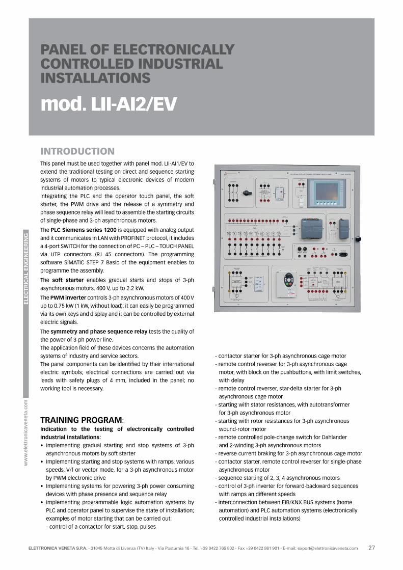
INTRODUCTIONThis panel must be used together with panel mod. LII-AI1/EV to
extend the traditional testing on direct and sequence starting
systems of motors to typical electronic devices of modern
industrial automation processes.
Integrating the PLC and the operator touch panel, the soft
starter, the PWM drive and the release of a symmetry and
phase sequence relay will lead to assemble the starting circuits
of single-phase and 3-ph asynchronous motors.
The PLC Siemens series 1200 is equipped with analog output
and it communicates in LAN with PROFINET protocol, it includes
a 4-port SWITCH for the connection of PC – PLC – TOUCH PANEL
via UTP connectors (RJ 45 connectors). The programming
software SIMATIC STEP 7 Basic of the equipment enables to
programme the assembly.
The soft starter enables gradual starts and stops of 3-ph
asynchronous motors, 400 V, up to 2.2 kW.
The PWM inverter controls 3-ph asynchronous motors of 400 V
up to 0.75 kW (1 kW, without load): it can easily be programmed
via its own keys and display and it can be controlled by external
electric signals.
The symmetry and phase sequence relay tests the quality of
the power of 3-ph power line.
The application field of these devices concerns the automation
systems of industry and service sectors.
The panel components can be identified by their international
electric symbols; electrical connections are carried out via
leads with safety plugs of 4 mm, included in the panel; no
working tool is necessary.
TRAINING PROGRAM:Indication to the testing of electronically controlled industrial installations:• Implementing gradual starting and stop systems of 3-ph
asynchronous motors by soft starter
• Implementing starting and stop systems with ramps, various
speeds, V/f or vector mode, for a 3-ph asynchronous motor
by PWM electronic drive
• Implementing systems for powering 3-ph power consuming
devices with phase presence and sequence relay
• Implementing programmable logic automation systems by
PLC and operator panel to supervise the state of installation;
examples of motor starting that can be carried out:
- control of a contactor for start, stop, pulses
PANEL OF ELECTRONICALLY CONTROLLED INDUSTRIAL INSTALLATIONS
mod. LII-AI2/EV
- contactor starter for 3-ph asynchronous cage motor
- remote control reverser for 3-ph asynchronous cage
motor, with block on the pushbuttons, with limit switches,
with delay
- remote control reverser, star-delta starter for 3-ph
asynchronous cage motor
- starting with stator resistances, with autotransformer
for 3-ph asynchronous motor
- starting with rotor resistances for 3-ph asynchronous
wound-rotor motor
- remote controlled pole-change switch for Dahlander
and 2-winding 3-ph asynchronous motors
- reverse current braking for 3-ph asynchronous cage motor
- contactor starter, remote control reverser for single-phase
asynchronous motor
- sequence starting of 2, 3, 4 asynchronous motors
- control of 3-ph inverter for forward-backward sequences
with ramps an different speeds
- interconnection between EIB/KNX BUS systems (home
automation) and PLC automation systems (electronically
controlled industrial installations)
ELE
CT
RIC
AL
EN
GIN
EE
RIN
G
28 ELETTRONICA VENETA S.P.A. - 31045 Motta di Livenza (TV) Italy - Via Postumia 16 - Tel. +39 0422 765 802 - Fax +39 0422 861 901 - E-mail: [email protected]
TECHNICAL CHARACTERISTICS:
The framework has been made with structural and sheet steel,
chemically treated and painted with epoxy varnish; its left side
is provided with hinges for a quick insertion/removal in/from
the wheeled structure or work bench.
All the necessary electric components for the correct power
supply of circuits are included in the panel.
Tests can be carried out via safety terminals and cables for
plugs with diameter of 4 mm.
Main components installed:• 1 static starter of gradual start and stop for 3-ph
asynchronous motors of 400 V up to 2.2 kW, with bypass relay
for exclusion of semiconductors at the end of the starting
phase and possibility of setting the initial torque value, input
3 x 400 Vac, control with external voltage of 24…110 Vac/dc
or of 110…400 Vac
• 1 PWM inverter for 3-ph asynchronous motors 400 V up to
0.75 kW (1 kW, without load); input 3 x 400 V; V/f, constant-
torque or vector output; it includes programming keys and
display, 6 programmable digital inputs, 2 programmable
analog inputs 0-10 Vdc / 0-4-20 mAdc, 1 relay for alarm
outputs
• 1 presence, symmetry and sequence phase relay – 3 x
400 Vac
• 1 three-pole switch 400 V – 16 A for power circuits
• 1 PLC S71200 CPU 1214C, 24 I/O, with 14 digital inputs of 24
Vdc, 10 digital transistor outputs of 24 Vdc – 0.5 A with clean-
contact relay interfaces of 24 Vdc / 230 Vac – 10 A max., 2
inputs and 1 analog output of 0-10 Vdc; it also includes a
PROFINET interface for the communication with a PC or from
CPU to CPU
• 1 colour operator Touch panel 6” with 6 programmable
function keys
• 1 software SIMATIC STEP 7 Basic that includes WinCC
Basic for programming controllers S7-1200 and configuring
operator Panels
• 1 four-port Switch module ETERNET RJ45 for PROFINET/
ETERNET networks
• 3 UTP connectors for connections of PC – PLC – Operator
panel (2 of 0.5 m and 1 of 2 m)
• 1 power supply unit of 24 Vdc – 3 A, with input of 100-240
Vac, for powering PLC and operator panel
• 2 variable analog outputs of 0…10 Vdc that can be used as
reference and control signals
• 2 lever switches for inserting digital logic states
• 1 board-type power plug (2P + earth) with 1 cable 3 x 0.75
mm²
Dimensions of working area: 730 x 730 mm
Dimensions of the panel: 790 x 790 x 200 mm
Weight: 18 kgPOWER SUPPLY:Single-phase 230 V - 50-60 Hz - 100 VA
Three-phase 3 x 400 V - 3 kVA
ACCESSORIES OF THE EQUIPMENT:
• Set of 20 cables with safety plugs (Ø 4 mm)
THEORETICAL-EXPERIMENTAL HANDBOOKSPractical handbook of industrial installations.
This panel can be used in different ways:
• it can be inserted in the wheeled structure of the integrated
laboratory of installations mod. LII-S/EV from which it is
powered;
• it can be inserted in the bench for exercises on installations
mod. 397-4/EV from which it is powered;
• it can be inserted in one of the mobile floor-standing display
rack with work top for instruments:
- mod. LII-T/EV; in this case, it is powered via the nearest
3-ph socket;
- mod. LII-T1/EV, from which it is powered;
• it can be applied onto a wall like a blackboard; in this case, it
is powered via the nearest 3-ph socket.

ELE
CT
RIC
AL
EN
GIN
EE
RIN
G
29ELETTRONICA VENETA S.P.A. - 31045 Motta di Livenza (TV) Italy - Via Postumia 16 - Tel. +39 0422 765 802 - Fax +39 0422 861 901 - E-mail: [email protected]
INTRODUCTIONThis panel is designed to test industrial systems with electronic
devices for control of power factor correction in low-voltage
power consuming devices (voltage of 400 V).
The panel is used to assemble automatic power correction
circuits with different capacitive steps and managed by an
electronic control unit. Two energy analyzers measure voltages,
currents, active, reactive and apparent powers and the power
factor.
These instruments are configured in single-phase or 3-ph
systems with or without neutral conductor; their use is free
in circuits such as power supply line, electric power consumer
device, capacitive battery, etc…
Components can be identified in the panel by their international
electric symbols; electrical connections are carried out easily
via leads and jumpers with safety plugs of 4 mm, included in
the panel; no working tool is necessary.
The electric power consuming devices with different values
of (active-inductive) apparent power can easily be reproduced
in laboratory with the combined use of variable resistive and
inductive loads.
The complete test set require a inductive active-reactive
power loads ranging between 1300 and 19000 W + 1300-1900
VAR, with adjustment in 5…7 steps. We suggest over variable
loads mod. RL-2/EV + IL-2/EV or mod. RL-3/EV + IL-3/EV or
mod. RL-2K/EV.
TRAINING PROGRAM:
Indication to the testing of automatic power factor correction systems:• Measurements of Apparent, Active and Reactive powers and
relations among them
• Local power factor correction system of single-phase power
consuming devices
• Local power factor correction system of 3-ph power
consuming devices
• Discharging the capacitors
• Centralized power factor correction systems with automatic
electronic board, with 1-2-3 equal steps
• Centralized power factor correction systems with automatic
electronic board, with 1-2-3-4 steps (one double of the other)
• Filtering harmonic currents in capacitors
PANEL OF AUTOMATIC POWER FACTOR CORRECTION
mod. LII-AI3/EV
TECHNICAL CHARACTERISTICS:
The framework has been made with structural and sheet steel,
chemically treated and painted with epoxy varnish; its left side
is provided with hinges for a quick insertion/removal in/from
the wheeled structure or work bench.
All the necessary electric components for the correct power
supply of circuits are included in the panel.
Tests can be carried out via safety terminals and cables for
plugs with diameter of 4 mm.
Main components installed:• 1 automatic power factor microprocessor controller, with
rated voltage 380..415 V – 50-60 Hz - ammeter input with
forward current up to 5 A (sensitivity range 0, 125 … 6 A) -
setting power factor: 0.8 ind … 0.8 cap., reconnection time:
5 … 240 s - sensitivity range: 5…600 s/step - 5 relay outputs
with contacts of 5 A – 250 Vac - setting parameters manually
from display-assisted keyboard
ELE
CT
RIC
AL
EN
GIN
EE
RIN
G
30 ELETTRONICA VENETA S.P.A. - 31045 Motta di Livenza (TV) Italy - Via Postumia 16 - Tel. +39 0422 765 802 - Fax +39 0422 861 901 - E-mail: [email protected]
POWER SUPPLY:Single-phase 230 V - 50-60 Hz - 50 VA
Three-phase 3 x 400 V - 50-60 Hz -3 kVA
ACCESSORIES OF THE EQUIPMENT:
• Set of 67 cables and of 20 jumpers with safety plugs (Ø 4 mm)
OPTION:Programming software and cable (accessories available on
demand, separately). Applying the programming software via
RS232 port (or USB port, with a converter) will enable to carry
out setting and simultaneous display of all measures (current
power factor, set power factor, weekly average power factor,
voltage, current, reactive power of system) in the automatic
power factor controller to obtain a whole view of power factor
correction system. Furthermore, the elapsed time and the
number of tripping operations from the setting at work of the
system are indicated for each step, for preliminary service of
contactors.
• 2 multi-function instruments; auxiliary power supply: 115-
230 V; graphic LCD of 128x80 pixels - measurement of
voltages, currents, active, reactive and apparent powers, and
power factor in single-phase and 3-ph systems - accuracy
rating for currents and voltages: ± 0.5% - measuring range: 5
A – 830 V max.
• 1 four-pole rotary switch of operation – 16 A – 400 V
• 1 set of three fuse holders with gl-type fuses 10.3x38 of 6 A
• 1 pair of fuse holders with gl-type fuses 10.3x38 of 2 A
• 1 fuse holder with gl-type fuse 10.3x38 of 4 A
• 1 noise suppression filter for 3-ph line with neutral – Un 440
V; In 10 A; inductance of 0.4 mH, current-carrying capacity of
0.1 μF
• 4 three-pole contactors for power factor correction – Ith
(AC1) 25 A (7.5 kVAR at 400 V) with transient limiting devices
at the connection, excitation of 24 Vac – 50-60 Hz, 2 auxiliary
NC contacts
• 1 single-phase transformer with primary winding of 230-400
V and secondary winding of 24 V, power of 72 VA
• 1 battery of 3-ph capacitors, 450 Vac, with selector between
2 and 4 μF and discharging resistors 100 kΩ - 5 W
• 2 batteries of 3-ph capacitors, 450 Vac, with selector between
4 and 8 μF and discharging resistors 50 kΩ - 10 W
• 1 battery of 3-ph capacitors,450 Vac, with selector between
8 and 16 μF and discharging resistors 50 kΩ - 10 W
All capacitor batteries can be connected in single-phase
or 3-ph (star-delta configuration). They enable to assemble
automatic power factor correction systems with up to 3 equal
steps (4+4+4 μF, 8+8+8 μF), or with up to 3 steps (one double of
the other, of 2, 4, 8 μF, or of 4, 8, 16 μF); connecting the various
batteries in parallel will lead to further combinations.
Dimensions of working area: 730 x 730 mm
Dimensions of the panel: 790 x 790 x 200 mm
Weight: 22 kg
THEORETICAL-EXPERIMENTAL HANDBOOKSPractical handbook of industrial installations.
This panel can be used in different ways:
• it can be inserted in the wheeled structure of the integrated
laboratory of installations mod. LII-S/EV from which it is
powered;
• it can be inserted in the bench for exercises on installations
mod. 397-4/EV from which it is powered;
• it can be inserted in one of the mobile floor-standing display
rack with work top for instruments:
- mod. LII-T/EV; in this case, it is powered via the nearest
3-ph socket;
- mod. LII-T1/EV, from which it is powered;
• it can be applied onto a wall like a blackboard; in this case, it
is powered via the nearest 3-ph socket.
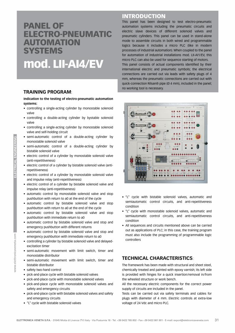
ELE
CT
RIC
AL
EN
GIN
EE
RIN
G
31ELETTRONICA VENETA S.P.A. - 31045 Motta di Livenza (TV) Italy - Via Postumia 16 - Tel. +39 0422 765 802 - Fax +39 0422 861 901 - E-mail: [email protected]
PANEL OFELECTRO-PNEUMATIC AUTOMATION SYSTEMS
mod. LII-AI4/EV
TRAINING PROGRAM:
Indication to the testing of electro-pneumatic automation systems:• controlling a single-acting cylinder by monostable solenoid
valve
• controlling a double-acting cylinder by bystable solenoid
valve
• controlling a single-acting cylinder by monostable solenoid
valve and self-holding circuit
• semi-automatic control of a double-acting cylinder by
monostable solenoid valve
• semi-automatic control of a double-acting cylinder by
bistable solenoid valve
• electric control of a cylinder by monostable solenoid valve
(anti-repetitiveness)
• electric control of a cylinder by bistable solenoid valve (anti-
repetitiveness)
• electric control of a cylinder by monostable solenoid valve
and impulse relay (anti-repetitiveness)
• electric control of a cylinder by bistable solenoid valve and
impulse relay (anti-repetitiveness)
• automatic control by monostable solenoid valve and stop
pushbutton with return to a0 at the end of the cycle
• automatic control by bistable solenoid valve and stop
pushbutton with return to a0 at the end of the cycle
• automatic control by bistable solenoid valve and stop
pushbutton with immediate return to a0
• automatic control by bistable solenoid valve and stop and
emergency pushbutton with different returns
• automatic control by bistable solenoid valve and stop and
emergency pushbutton with immediate return to a0
• controlling a cylinder by bistable solenoid valve and delayed-
excitation timer
• semi-automatic movement with limit switch, timer and
monostable distributor
• semi-automatic movement with limit switch, timer and
bistable distributor
• safety two-hand control
• pick-and-place cycle with bistable solenoid valves
• pick-and-place cycle with monostable solenoid valves
• pick-and-place cycle with monostable solenoid valves and
safety and emergency circuits
• pick-and-place cycle with bistable solenoid valves and safety
and emergency circuits
• “L” cycle with bistable solenoid valves
INTRODUCTIONThis panel has been designed to test electro-pneumatic
automation systems including the pneumatic circuits and
electric slave devices of different solenoid valves and
pneumatic cylinders. This panel can be used in stand-alone
mode to assemble circuits in both wired and programmable
logics because it includes a micro PLC (like in modern
processes of industrial automation). When coupled to the panel
for automation of industrial installations mod. LII-AI1/EV, this
micro PLC can also be used for sequence starting of motors.
This panel consists of actual components identified by their
international electric and pneumatic symbols; the electrical
connections are carried out via leads with safety plugs of 4
mm, whereas the pneumatic connections are carried out with
quick-connection Rilsan® pipe (Ø 4 mm), included in the panel;
no working tool is necessary.
• “L” cycle with bistable solenoid valves, automatic and
semiautomatic control circuits, and anti-repetitiveness
condition
• “L” cycle with monostable solenoid valves, automatic and
semiautomatic control circuits, and anti-repetitiveness
condition
• All sequences and circuits mentioned above can be carried
out as applications of PLC; in this case, the training program
must also include the programming of programmable logic
controllers
TECHNICAL CHARACTERISTICS:
The framework has been made with structural and sheet steel,
chemically treated and painted with epoxy varnish; its left side
is provided with hinges for a quick insertion/removal in/from
the wheeled structure or work bench.
All the necessary electric components for the correct power
supply of circuits are included in the panel.
Tests can be carried out via safety terminals and cables for
plugs with diameter of 4 mm. Electric controls at extra-low
voltage of 24 Vdc and micro PLC.
ELE
CT
RIC
AL
EN
GIN
EE
RIN
G
32 ELETTRONICA VENETA S.P.A. - 31045 Motta di Livenza (TV) Italy - Via Postumia 16 - Tel. +39 0422 765 802 - Fax +39 0422 861 901 - E-mail: [email protected]
POWER SUPPLY:Single-phase 100…240 V - 50-60 Hz - 72 VA
ACCESSORIES OF THE EQUIPMENT:
• 1 board-type power plug (2P + earth) with 1 cable 3 x 0.75 mm²
• 1 slider valve for pneumatic feeding
• 10 m of spiral pipe (Ø 8) and airtight quick connect unions for
compressed air feeding
• set of 40 cables with safety plugs (Ø 4 mm)
• 10 + 10 m of pipe Rilsan® (Ø 4 mm) of different colours
• 1 extractor for unthreading Rilsan® pipe from quick
connections
• 1 cutter for Rilsan® pipe
ACCESSORY RECOMMENDED IF COMPRESSED AIR IS NOT AVAILABLE:Silent compressor provided with tank, overpressure valve,
pressure reducer (0.2…8 bars), pressure gauge of 0…10 bars,
filter with dehumidifier of automatic discharge, M.12 MINI
¼”connection fitting.
Further technical characteristics:
• capacity: 20 l
• flow rate: 55 l/min
• pressure: 7 bars
• power supply: single-phase, 230 V – 50-60 Hz
• motor power: 0.5 kW
• number of revolutions per minute: 1400 r.p.m.
• noise level: < 57 dB+
• automatic thermal protection
• dimensions: 650 x 350 x 750 mm
• weight: 30 kg
OPTION:• Design, simulation and animation software for electric,
pneumatic and electro-pneumatic circuits mod. SW-AIR/EV
• Interface card mod. C2-IO/EV
Electric controls at extra-low voltage of 24 Vdc and micro PLC • 1 micro PLC LOGO Siemens, with 20 I/O, 12 digital inputs of
24 Vdc of which 4 are also analog 0-10 Vdc and 4 fast inputs
up to 5 kHz, 4 digital relay outputs of 24 Vdc / 230 Vac – 10 A
max. + 4 digital relay outputs of 24 Vdc / 230 Vac – 5 A max.;
programming via its own keys and via PC (software and USB
cable for PC connection included)
• 1 regulated power supply unit, with input of 100…240 V 50-
60 Hz, output of 24 Vdc – 3 A
• 22 multi-voltage, multi-function (TON, TOFF, PULSE) and
multi-range (from 0.1 s to 10 days) timers
• 2 auxiliary relays for industrial uses, with 3 exchange
contacts (250 Vac – 10 A / 24 Vdc - 2 A) and coil of 24 Vdc
• 1 one-piece button including start key with NO and NC
contact, stop key with NO and NC contact and warning light
of 24 V
• 1 red mushroom-head emergency button with 1 NO contact
and 2 NC contacts
• 1 butterfly selector switch of three positions, with two NO
and NC contacts and warning light of 24 V
Pneumatic actuators• 1 single-acting cylinder (Ø 20 mm; l = 100 mm), with magnetic
piston, quick-connection unions for pipe Ø 4 mm and
unidirectional flow control valve mounted onto the cylinder
• 2 double-acting cylinders (Ø 20 mm; l = 100 mm), with
magnetic pistons, quick-connection unions for pipe Ø 4 mm
and 2 unidirectional flow control valves mounted onto the
cylinders
Sensors and limit switches• 4 magnetic reed sensors with LEDs, fixed onto the double-
acting cylinders (Ø 20 mm), provided with interface to obtain
separated NO and NC contacts
• 1 electric limit switch enabled by the negative stroke of
single-acting cylinder, with 1 exchange contact
• 1 optical proximity sensor with reflector, enabled by
the positive stroke of single-acting cylinder, NO/NC
programmable contact
• 1 pressure sensor with display (analog and digital output)
• group of solenoid valves
• two 5/2 bistable solenoid valves, powered with 24 Vdc, with
enabling LED, quick-connection unions for pipe Ø 4 mm
provided with check valves
• two 5/2 monostable solenoid valves, powered with 24 Vdc,
with enabling LED (they also act as 3/2 solenoid valves) and
quick-connection unions for pipe Ø 4 mm provided with
check valves
Dimensions of working area: 730 x 730 mm
Dimensions of the panel: 790 x 790 x 200 mm
Weight: 23 kg
THEORETICAL-EXPERIMENTAL HANDBOOKSPractical handbook of industrial installations.
This panel can be used in different ways:
• it can be inserted in the wheeled structure of the integrated
laboratory of installations mod. LII-S/EV from which it is
powered;
• it can be inserted in the bench for exercises on installations
mod. 397-4/EV from which it is powered;
• it can be inserted in one of the mobile floor-standing display
rack with work top for instruments:
- mod. LII-T/EV; in this case, it is powered via the nearest
3-ph socket;
- mod. LII-T1/EV, from which it is powered;
• it can be applied onto a wall like a blackboard; in this case, it
is powered via the nearest 3-ph socket.
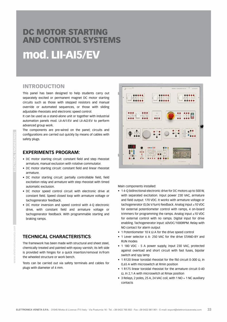
ELE
CT
RIC
AL
EN
GIN
EE
RIN
G
33ELETTRONICA VENETA S.P.A. - 31045 Motta di Livenza (TV) Italy - Via Postumia 16 - Tel. +39 0422 765 802 - Fax +39 0422 861 901 - E-mail: [email protected]
INTRODUCTIONThis panel has been designed to help students carry out
separately excited or permanent magnet DC motor starting
circuits such as those with stepped resistors and manual
override or automated sequences, or those with sliding
adjustable rheostats and electronic speed control.
It can be used as a stand-alone unit or together with industrial
automation panels mod. LII-AI1/EV and LII-AI2/EV to perform
advanced group work.
The components are pre-wired on the panel; circuits and
configurations are carried out quickly by means of cables with
safety plugs.
EXPERIMENTS PROGRAM:• DC motor starting circuit: constant field and step rheostat
armature, manual exclusion with rotative commutator.
• DC motor starting circuit: constant field and linear rheostat
armature.
• DC motor starting circuit: partially controllable field, field
excitation relay and armature with step rheostat with timed
automatic exclusion.
• DC motor speed control circuit with electronic drive at
constant field. Speed closed loop with armature voltage or
tachogenerator feedback.
• DC motor inversion and speed control with 4-Q electronic
drive, with constant field and armature voltage or
tachogenerator feedback. With programmable starting and
braking ramps.
TECHNICAL CHARACTERISTICS:
The framework has been made with structural and sheet steel,
chemically treated and painted with epoxy varnish; its left side
is provided with hinges for a quick insertion/removal in/from
the wheeled structure or work bench.
Tests can be carried out via safety terminals and cables for
plugs with diameter of 4 mm.
Main components installed:
• 1 4-Q bidirectional electronic drive for DC motors up to 500 W,
with separated excitation. Input power 230 VAC, armature
and field output: 170 VDC. It works with armature voltage or
tachogenerator (0,06 V/turn) feedback. Analog input ±10 VDC
for external potentiometer control with ramps, 4 on-board
trimmers for programming the ramps. Analog input ±10 VDC
for external control with no ramps. Digital input for drive
enabling. Tachogenerator input: 60VDC/1000RPM. Relay with
NO contact for alarm output
• 1 Potentiometer 10 k Ω A for the drive speed control
• 1 Lever selector 6 A- 250 VAC for the drive STAND-BY and
RUN modes
• 1 180 VDC - 5 A power supply, input 230 VAC, protected
against overload and short circuit with fast fuses, bipolar
switch and spy lamp
• 1 R120 linear toroidal rheostat for the fild circuit 0-300 Ω, In
0,65 A with microswitch at Rmin position
• 1 R175 linear toroidal rheostat for the armature circuit 0-40
Ω, In 2,1 A with microswitch at Rmax position
• 3 Relays, 2 poles, 25 A, 24 VAC coil, with 1 NO + 1 NC auxiliary
contacts
DC MOTOR STARTINGAND CONTROL SYSTEMS
mod. LII-AI5/EV
ELE
CT
RIC
AL
EN
GIN
EE
RIN
G
34 ELETTRONICA VENETA S.P.A. - 31045 Motta di Livenza (TV) Italy - Via Postumia 16 - Tel. +39 0422 765 802 - Fax +39 0422 861 901 - E-mail: [email protected]
POWER SUPPLY:Single-phase 230 V - 50-60 Hz - 1000 VA
ACCESSORIES OF THE EQUIPMENT:
• DC motor, 500 W, 170 VDC armature and separated excitation
- mod. M-1G/EV
• Set of 40 cables with safety plugs Ø 4 mm
• Set of 6 cables with safety plugs Ø 2 mm
ACCESSORY RECOMMENDED (NOT INCLUDED)
• Tachogenerator 0,06 V / turn - mod. M-16/EV
This panel can be used in different ways:
• it can be inserted in the wheeled structure of the integrated
laboratory of installations mod. LII-S/EV from which it is
powered;
• it can be inserted in the bench for exercises on installations
mod. 397-4/EV from which it is powered;
• it can be inserted in one of the mobile floor-standing display
rack with work top for instruments:
- mod. LII-T/EV; in this case, it is powered via the nearest
3-ph socket;
- mod. LII-T1/EV, from which it is powered;
• it can be applied onto a wall like a blackboard; in this case, it
is powered via the nearest 3-ph socket.
• 1 3-step 1 way adder-type switch, 25 A, for manual starting
of the DC motor
• 1 programmable electronic relay for min/max AC/DC current,
auxiliary input 230 VDC, selectable current ranges 1, 2, 5 A,
NO-COM-C auxiliary contact
• 1 monoblock pushbutton, RUN key with NO contact, STOP
key with NC contact, spy lamp 24 V
• 1 red emergency pushbutton, manual unlocking, with 2 NC
contacts
• 2 multifunction multivoltage timers, TON, TOFF, PULSE,
multiscale 0,1 s to 10 days
• 1 24 VAC PELV output with single-ph transformer, 115/230 V /
24 V - 50 VA, 50-60 Hz. Protected with 2 A fast fuse
• 1 panel feeding socket 2P + G and 5 x 20 10 A fuse
• 1 single-ph feeding cable with French-German plug
Dimensions of working area: 730 x 730 mm
Dimensions of the panel: 790 x 790 x 200 mm
Weight netto: 19 kg
THEORETICAL-EXPERIMENTAL HANDBOOKSPractical handbook of industrial installations.

ELE
CT
RIC
AL
EN
GIN
EE
RIN
G
35ELETTRONICA VENETA S.P.A. - 31045 Motta di Livenza (TV) Italy - Via Postumia 16 - Tel. +39 0422 765 802 - Fax +39 0422 861 901 - E-mail: [email protected]
Thickness: 20/10 mm; galvanized steel. Holes of 4 mm are
drilled on the whole surface with a spacing of 12 mm. This
panel is equipped with hinges for a quick insertion in the bench.
Suitable for industrial electric installations.
Dimensions: 790 x 790 mm
Weight: 7,5 kg
Example with thematerial of MI-P/EV
PANEL OF PIERCED METAL SHEETMod. 397-PLF/EV
KIT FOR INDUSTRIAL INSTALLATIONSMod. MI-P/EV
TRAINING PROGRAM:
• Controlling a contactor from a point
• Impulse control of a contactor
• Separate control of two contactors
• Remote control reverser
• Remote control reverser with block on pushbuttons
• Remote control reverser with timer
• Start-delta starter
• Starting by stator resistances
• Starting by autotransformer
• Starting by rotor resistances by steps
• Remote controlled pole-change switch for two-winding motors
• Remote controlled pole-change switch for single-winding
(Dahlander) motor
• Reverse current braking
• Remote control reverser, star-delta starter
COMPONENTS INCLUDED IN THE KIT:
• 1 set of three fuse holders with fuses 10.3x38 up to 25 A - 400 Vac
• 6 fuses 10.3 x 38 with current of 6 A
• 1 mushroom-head emergency button with 1 NO contact +
1 NC 10 A – 250 Vac
• 3 pushbuttons of different colours with 1 NO contact + 1 NC
10 A – 250 Vac
• 4 lamp socket for warning lights with diameter of 22 mm, of
different colours, including lamps Ba9s – 24 V – 3 W
• 5 three-pole contactors of 25 A – 400 Vac, 2 auxiliary NO
contacts + 2 NC 10 A – 250 Vac, coil of 24 Vac
• 1 three-pole thermal relay with rated current of 4.5 – 7.5 A,
1 NO contact + 1 NC 10 A – 250 Vac
• 3 multi-function timers (delayed closing, delayed opening)
with NO / NC exchange contact 10 A – 250 Vac, coil of 24 Vac
• 1 auxiliary relay, 2 auxiliary NO contacts + 2 NC 10 A –
250 Vac, coil of 24 Vac
• 1 single-phase transformer 115/230 – 12/24 V 50 VA
• 2 boxes for 4 button operators / lamp socket
• 30 screws M4 x 10-20 mm with nuts and washers
• 2 pieces of 30 cm for fixing modular components
THEORETICAL-EXPERIMENTAL HANDBOOKSPractical handbook of electric installations.

ELE
CT
RIC
AL
EN
GIN
EE
RIN
G
36 ELETTRONICA VENETA S.P.A. - 31045 Motta di Livenza (TV) Italy - Via Postumia 16 - Tel. +39 0422 765 802 - Fax +39 0422 861 901 - E-mail: [email protected]
KIT FOR ELECTRO-PNEMATIC SYSTEMSMod. ME/EV
TRAINING PROGRAM:
ELECTRO-PNEUMATIC SYSTEMS• Controlling a cylinder by monostable solenoid valve
• Controlling a cylinder by bystable solenoid valve
• Controlling a cylinder by monostable solenoid valve and self-
holding circuit
• Temporary storage with prevalent insertion
• Temporary storage with prevalent reset
• Temporary binary counter for circuits with bistable solenoid valve
• Temporary binary counter for circuits with monostable
solenoid valve
• Permanent binary counter for circuits with bistable solenoid valve
• Permanent binary counter for circuits with monostable
solenoid valve
• Control of a sliding door
• Semi-automatic control of a double-acting cylinder by
monostable solenoid valve
• Semi-automatic control of a double-acting cylinder by
bistable solenoid valve
• Electric control of a cylinder by monostable solenoid valve
(anti-repetitiveness)
• Electric control of a cylinder by bistable solenoid valve
(anti-repetitiveness)
• Electric control of a cylinder by monostable solenoid valve
and impulse relay (anti-repetitiveness)
• Electric control of a cylinder by bistable solenoid valve and
impulse relay (anti-repetitiveness)
• Automatic control by monostable solenoid valve and stop
pushbutton with return to a0 at the end of the cycle
• Automatic control by bistable solenoid valve and stop
pushbutton with return to a0 at the end of the cycle
• Automatic control by bistable solenoid valve and stop
pushbutton with immediate return to a0
• Automatic control by bistable solenoid valve and stop and
emergency pushbutton with different returns
• Automatic control by bistable solenoid valve and stop and
emergency pushbutton with immediate return to a 0
• Controlling a cylinder by bistable solenoid valve and
delayed-excitation timer
• Electric diagrams for using delayed-excitation timer, with
monostable solenoid valve and instantaneous contact
• Semi-automatic control of a cylinder, with bistable distributor,
delayed excitation
• Semi-automatic control of a cylinder, with bistable distributor,
delayed excitation and exchange contact
• Semi-automatic movement with limit switch, timer and
monostable distributor
• Semi-automatic movement with limit switch, timer and
bistable distributor
• Safety two-hand control
LOGICAL FUNCTIONS IMPLEMENTED WITH FUNCTIONAL ELECTRIC DIAGRAMS
• identity function (YES)
• inverse function (NOT)
• sum function (inclusive OR)
• exclusive OR
• product function (AND)
• inhibition function
• examples of logical equations
INDUSTRIAL APPLICATIONS
• pick-and-place cycle with bistable solenoid valves
• pick-and-place cycle with monostable solenoid valves
• pick-and-place cycle with monostable solenoid valves and
safety and emergency circuits
• pick-and-place cycle with bistable solenoid valves and safety
and emergency circuits
• “L” cycle with bistable solenoid valves
• “L” cycle with bistable solenoid valves, automatic and
semiautomatic control circuits, and anti-repetitiveness
condition
• “L” cycle with monostable solenoid valves, automatic and
semiautomatic control circuits, and anti-repetitiveness
condition
ELE
CT
RIC
AL
EN
GIN
EE
RIN
G
37ELETTRONICA VENETA S.P.A. - 31045 Motta di Livenza (TV) Italy - Via Postumia 16 - Tel. +39 0422 765 802 - Fax +39 0422 861 901 - E-mail: [email protected]
COMPONENTS INCLUDED IN THE KIT:
• 1 single-phase transformer 115-230 / 12-24 V – 72 VA
• 2 multifunction multivoltage timers, TON, TOFF, PULSE,
multiscale 0,1 s to 10 days
• 2 auxiliary relays 3 exchange contacts 10 A - 250 Vca,
excitation of 24 Vac complete with undecal socket
• 2 fuse holders with breakable neutral complete of
cylindrical fuses 10,3 x 38 da 4 A
• 3 push-buttons for industrial uses with auxiliary NO and NC
contact 10 A - 250 Vca
• 1 impulse relay (two-way switch) with coil of 24 Vca
• 1 nylon spiral pipe Rilsan® (10 m), provided with connections
M 12 MINI of ¼”
• 20 m of coloured nylon pipe Rilsan®, 4 x 2.5
• 2 m of neutral nylon pipe Rilsan®, 6 x 4
• 1 filter/reducer/pressure gauge assembly
• 1 bistable directional valve of ¼”, controlled by side lever
• 1 distribution frame of 4 connections, ¼”
• Two 5/2 solenoid valves, solenoid-solenoid, 24 Vac 50-60 Hz
• Two 5/2 solenoid valves, solenoid-spring, 24 Vac 50-60 Hz
• 6 light connectors for solenoid valves
• 2 double-acting cylinders provided with 2 magnetic sensors,
pins, nuts and cam on rod
• 1 silencer of 1/8”
• 1 malew quick connection of ¼”
• 4 unions R1-6 – ¼”
• 12 unions R6-4 - 1/8”
• 12 L-shaped unions, R4 4
• 4 plastic plugs (Ø 4)
• 8 drain regulators of 1/8”
• 9 unions R1-4 of 1/8”
• 1 union R2-4 of 1/8”
• 1 male plug of ¼”
• 1 union R1-6 of 1/8”
RECOMMENDED ACCESSORIES:Silent compressor, provided with wheels and tank,
overpressure valve and pressure reducer with connection
fitting M.12 MINI ¼”.
Technical specifications of compressor:
• capacity: 20 l
• flow rate: 55 l/min
• pressure: 7 bars
• motor power: 0.5 kW
• revolutions per minute: 1400
• noise level: < 57 dB
• power supply: 230 V, single-phase – 50-60 Hz
• automatic thermal protection
• Dimensions: 650 x 350 x 750 mm
• Net weight: 30 kg
THEORETICAL-EXPERIMENTAL HANDBOOKSPractical handbook of industrial installations.
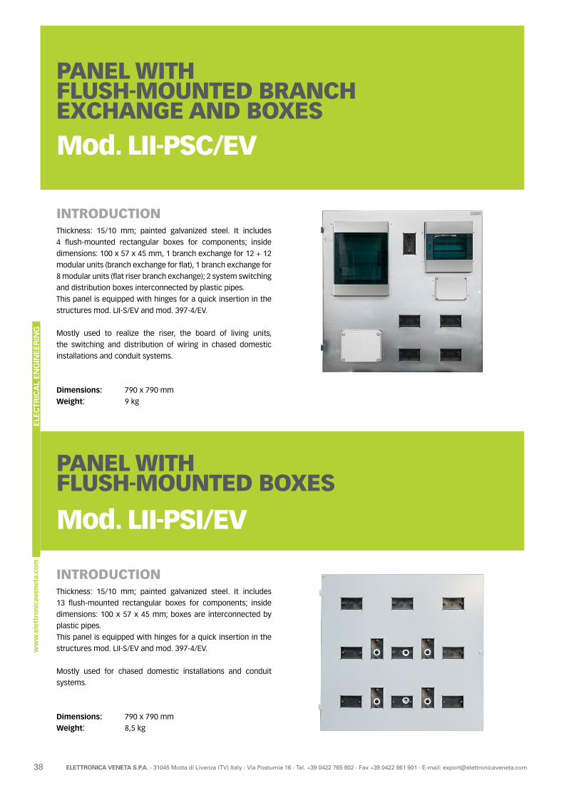
ELE
CT
RIC
AL
EN
GIN
EE
RIN
G
38 ELETTRONICA VENETA S.P.A. - 31045 Motta di Livenza (TV) Italy - Via Postumia 16 - Tel. +39 0422 765 802 - Fax +39 0422 861 901 - E-mail: [email protected]
PANEL WITHFLUSH-MOUNTED BRANCHEXCHANGE AND BOXES
Mod. LII-PSC/EV
INTRODUCTIONThickness: 15/10 mm; painted galvanized steel. It includes
4 flush-mounted rectangular boxes for components; inside
dimensions: 100 x 57 x 45 mm, 1 branch exchange for 12 + 12
modular units (branch exchange for flat), 1 branch exchange for
8 modular units (flat riser branch exchange); 2 system switching
and distribution boxes interconnected by plastic pipes.
This panel is equipped with hinges for a quick insertion in the
structures mod. LII-S/EV and mod. 397-4/EV.
Mostly used to realize the riser, the board of living units,
the switching and distribution of wiring in chased domestic
installations and conduit systems.
Dimensions: 790 x 790 mm
Weight: 9 kg
PANEL WITH FLUSH-MOUNTED BOXES
Mod. LII-PSI/EV
INTRODUCTIONThickness: 15/10 mm; painted galvanized steel. It includes
13 flush-mounted rectangular boxes for components; inside
dimensions: 100 x 57 x 45 mm; boxes are interconnected by
plastic pipes.
This panel is equipped with hinges for a quick insertion in the
structures mod. LII-S/EV and mod. 397-4/EV.
Mostly used for chased domestic installations and conduit
systems.
Dimensions: 790 x 790 mm
Weight: 8,5 kg

ELE
CT
RIC
AL
EN
GIN
EE
RIN
G
39ELETTRONICA VENETA S.P.A. - 31045 Motta di Livenza (TV) Italy - Via Postumia 16 - Tel. +39 0422 765 802 - Fax +39 0422 861 901 - E-mail: [email protected]
KIT FOR SWITCHBOARDS OF LIVING UNIT
Mod. MIS-Q/EV
TRAINING PROGRAM:
• application of AC-type differential circuit breaker
• application of A-type differential circuit breaker
• application of selective differential circuit breaker
• application of differential circuit breaker with automatic
reset
• application of magneto-thermal automatic circuit breakers
for lighting circuits, sockets and services
• application of fuses for protection of power and auxiliary
circuits
• application of Surge Protection Devices (SPD) against
overvoltages
COMPONENTS INCLUDED IN THE KIT:• 1 single-phase energy meter, direct connection, for currents
up to 40 A; selectable measurements of total and partial
active and reactive power, voltage, current, active and
reactive power, power factor, frequency, hour meter, average
active power (demand on 15 min.)
• 1 magneto-thermal automatic circuit breaker 2 x 16 A, curve C
• 1 magneto-thermal automatic circuit breaker 2 x 10 A, curve C
• 1 magneto-thermal automatic circuit breaker 2 x 6 A, curve C
• 1 pure selective “S” two-pole automatic differential circuit
breaker of 25 A / 0.3 A, AC class
• 1 two-pole A-type differential circuit breaker; Idn = 30 mA
• 1 two-pole AC-type differential circuit breaker; Idn = 30 mA
• 1 device for the automatic reset of differential circuit
breakers
• 1 pair of breakable fuse holders with cylindrical fuses 10.3 x
38 of 10 A
REMARK:The ideal application of kit MIS-Q/EV is in panel LII-PSC/EV.
THEORETICAL-EXPERIMENTAL HANDBOOKSPractical handbook of electric installations.

ELE
CT
RIC
AL
EN
GIN
EE
RIN
G
40 ELETTRONICA VENETA S.P.A. - 31045 Motta di Livenza (TV) Italy - Via Postumia 16 - Tel. +39 0422 765 802 - Fax +39 0422 861 901 - E-mail: [email protected]
KITS FOR LIGHTING INSTALLATIONS
Mod. MIS-I/EV
TRAINING PROGRAM:
• Lamp controlled by a switch
• Lamps controlled by a changeover switch
• Lamp controlled from two points
• Group of lamps controlled from two points + 1 socket
• Lamp controlled from 3 points
• Group of lamps controlled from 4 points + 2 sockets
• Lamp controlled from various points by relay
• Group of lamps controlled from various points by switch relay
• Control of a fluorescent lamp
• Lighting archives from 3 points
• Timed lighting of stairwell
COMPONENTS INCLUDED IN THE KITS:
• 1 switch 1P 16 A – 250 Vac
• 1 changeover switch (2 switches) 1P 16 A – 250 Vac
• 2 two-way switches 1P 16 A – 250 Vac
• 2 inverters 1P 16 A – 250 Vac
• 3 NO lighting pushbuttons 1P 10 A – 250 Vac
• 2 universal two-pin and Unel sockets 10-16 A – 230 V
• 2 square lamp sockets E27
• 2 lamps E27 – 220 V – 40n W
• 1 fuse holder for cylindrical fuses 6x32
• 2 cylindrical fuses 6x32 6 A
• 1 single-phase transformer 115/230 – 12/24 V 50 VA
• 1 switch relay with contacts 10 A – 250 Vac, coil of 24 Vac
• 1 fluorescent lamp 230 V – 18 W – connection G13, including
ballast, capacitos and starter
• 1 timing relay for stairwell lighting
• 6 supports of 3 controls
• 6 covering plates
• 10 false closing poles
• 3 closing lids
Material for embedded electrical installations.
THEORETICAL-EXPERIMENTAL HANDBOOKSPractical handbook of electric installations.

ELE
CT
RIC
AL
EN
GIN
EE
RIN
G
41ELETTRONICA VENETA S.P.A. - 31045 Motta di Livenza (TV) Italy - Via Postumia 16 - Tel. +39 0422 765 802 - Fax +39 0422 861 901 - E-mail: [email protected]
KIT FORSIGNALLING SYSTEMSMod. MIS-S/EV
Material for embedded electrical installations.
TRAINING PROGRAM:
• Ringer controlled from a point
• Ringer system with call and answer
• System for controlling 3 ringers
• Ringer system for 2 flats and an outdoor unit
• Ringer system for flats and electric lock
• Optical-acoustic signalling system for offices, schools,
hospitals
COMPONENTS INCLUDED IN THE KIT:
• 4 NO pushbuttons 1P 10 A - 250 Vac
• 2 NO pushbuttons 1P 10 A – 250 Vac + red warning light of 24 V
KIT FORINTERPHONESYSTEMSMod. MIS-C/EVTRAINING PROGRAM:
• Entry phone system with electric porter, 1 outdoor unit and
1, 2, 3 indoor units
• Phonic system between two intercommunicating interphones
• Phonic system between three intercommunicating interphones
and outdoor unit with relay of exclusion of outdoor speech
COMPONENTS INCLUDED IN THE KIT:
• 3 interphones provided with 1 door opening pushbutton and
3 pushbuttons for intercommunication
• 1 power supply unit for interphone system
• 1 phonic unit with microphone and loudspeaker
• 1 relay for excluding the outdoor unit for indoor
intercommunications
• 1 fuse holder for cylindrical fuses 6x32
• 2 cylindrical fuses 6x32 6 A
• 1 single-phase transformer 115/230 – 12/24 V 50 VA
• 3 ringers of 12 Vac
• 1 buzzer of 12 Vac
• 1 four-button strip with nameplate
• 1 receptacle for four-button strip
• 1 tag of numeric calls of 24 Vac with micro-coding
• 1 electric lock of 12 Vac
• 1 metallic support for electric lock
• 6 supports of 3 controls
• 6 covering plates
• 10 false closing poles
THEORETICAL-EXPERIMENTAL HANDBOOKSPractical handbook of electric installations.
THEORETICAL-EXPERIMENTAL HANDBOOKSPractical handbook of electric installations.
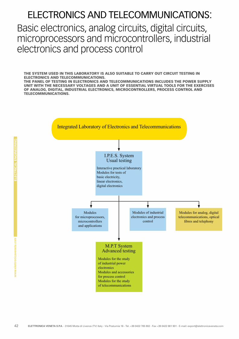
ELE
CT
RIC
AL
EN
GIN
EE
RIN
G
42 ELETTRONICA VENETA S.P.A. - 31045 Motta di Livenza (TV) Italy - Via Postumia 16 - Tel. +39 0422 765 802 - Fax +39 0422 861 901 - E-mail: [email protected]
Basic electronics, analog circuits, digital circuits, microprocessors and microcontrollers, industrial electronics and process control
ELECTRONICS AND TELECOMMUNICATIONS:
THE SYSTEM USED IN THIS LABORATORY IS ALSO SUITABLE TO CARRY OUT CIRCUIT TESTING IN ELECTRONICS AND TELECOMMUNICATIONS.THE PANEL OF TESTING IN ELECTRONICS AND TELECOMMUNICATIONS INCLUDES THE POWER SUPPLY UNIT WITH THE NECESSARY VOLTAGES AND A UNIT OF ESSENTIAL VIRTUAL TOOLS FOR THE EXERCISES OF ANALOG, DIGITAL, INDUSTRIAL ELECTRONICS, MICROCONTROLLERS, PROCESS CONTROL AND TELECOMMUNICATIONS.
Integrated Laboratory of Electronics and Telecommunications
Modulesfor microprocessors,
microcontrollersand applications
I.P.E.S. SystemUsual testing
Interactive practical laboratoryModules for tests ofbasic electricity,linear electronics,digital electronics
M.P.T SystemAdvanced testing
Modules for the studyof industrial power electronicsModules and accessories for process control Modules for the studyof telecommunications
Modules of industrial electronics and process
control
Modules for analog, digital telecommunications, optical
fibres and telephony
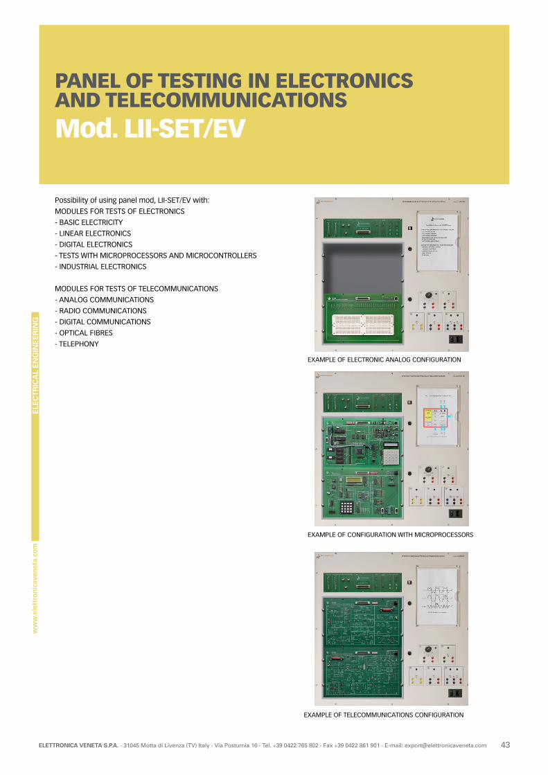
ELE
CT
RIC
AL
EN
GIN
EE
RIN
G
43ELETTRONICA VENETA S.P.A. - 31045 Motta di Livenza (TV) Italy - Via Postumia 16 - Tel. +39 0422 765 802 - Fax +39 0422 861 901 - E-mail: [email protected]
PANEL OF TESTING IN ELECTRONICS AND TELECOMMUNICATIONSMod. LII-SET/EV
Possibility of using panel mod, LII-SET/EV with:
MODULES FOR TESTS OF ELECTRONICS
- BASIC ELECTRICITY
- LINEAR ELECTRONICS
- DIGITAL ELECTRONICS
- TESTS WITH MICROPROCESSORS AND MICROCONTROLLERS
- INDUSTRIAL ELECTRONICS
MODULES FOR TESTS OF TELECOMMUNICATIONS
- ANALOG COMMUNICATIONS
- RADIO COMMUNICATIONS
- DIGITAL COMMUNICATIONS
- OPTICAL FIBRES
- TELEPHONY
EXAMPLE OF TELECOMMUNICATIONS CONFIGURATION
EXAMPLE OF CONFIGURATION WITH MICROPROCESSORS
EXAMPLE OF ELECTRONIC ANALOG CONFIGURATION

Elettronica Veneta S.p.A.Via Postumia, 1631045 Motta di Livenza (Treviso) ItalyTel. +39 0422 7657 r.a. - Fax +39 0422 860 784E-mail: [email protected]
www.elettronicaveneta.com