Embed Size (px)
Citation preview
NREL is a national laboratory of the U.S. Department of Energy, Office of Energy Efficiency and Renewable Energy, operated by the Alliance for Sustainable Energy, LLC.
Integrated Power Module Cooling
Kevin Bennion National Renewable Energy Laboratory May 14, 2013
Project ID: APE047
This presentation does not contain any proprietary, confidential, or otherwise restricted information.
2
Overview
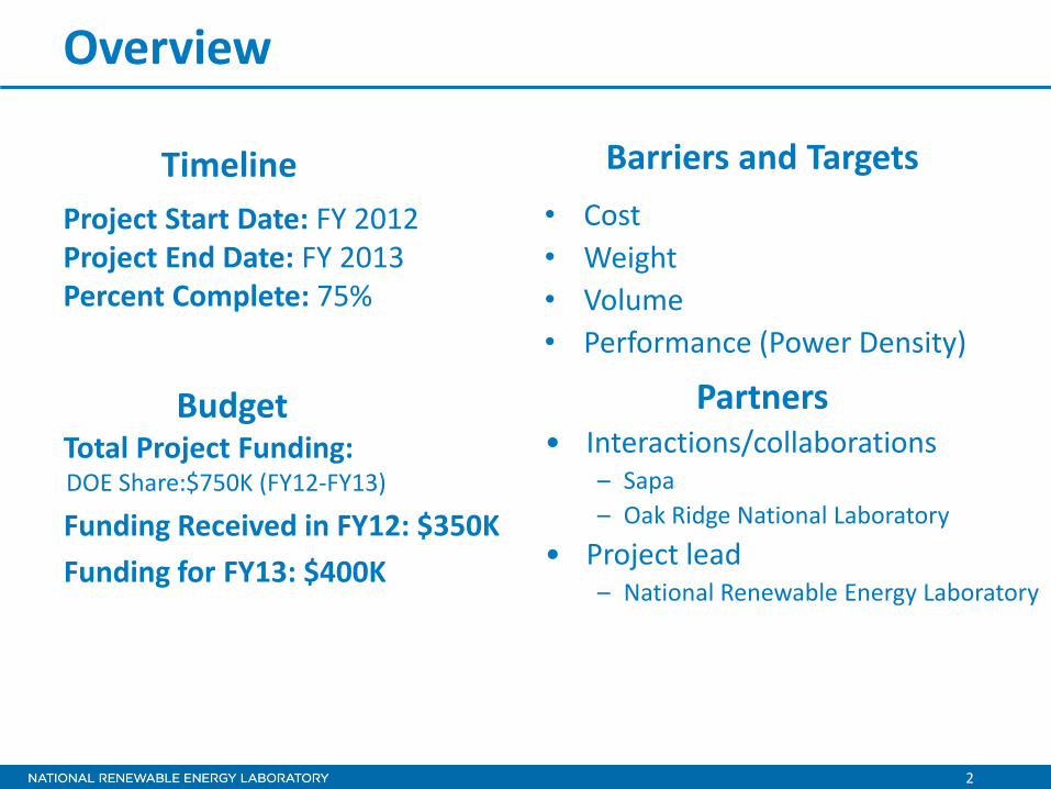
Project Start Date: FY 2012 Project End Date: FY 2013 Percent Complete: 75%
• Cost • Weight • Volume • Performance (Power Density)
Total Project Funding: DOE Share:$750K (FY12-FY13)
Funding Received in FY12: $350K Funding for FY13: $400K
Timeline
Budget
Barriers and Targets
• Interactions/collaborations – Sapa – Oak Ridge National Laboratory
• Project lead – National Renewable Energy Laboratory
Partners

3
Relevance
PCB Components
Capacitors
Connectors
Microprocessors Current Sensors Miscellaneous
Power Silicon
Thermal Management
Housing
46%
Synthesis Partners Projected Inverter Cost Drivers to 2016
Synthesis Partners LLC. “Technology and Market Intelligence: Hybrid Vehicle Power Inverters and Cost Analysis.” July 2011.
4
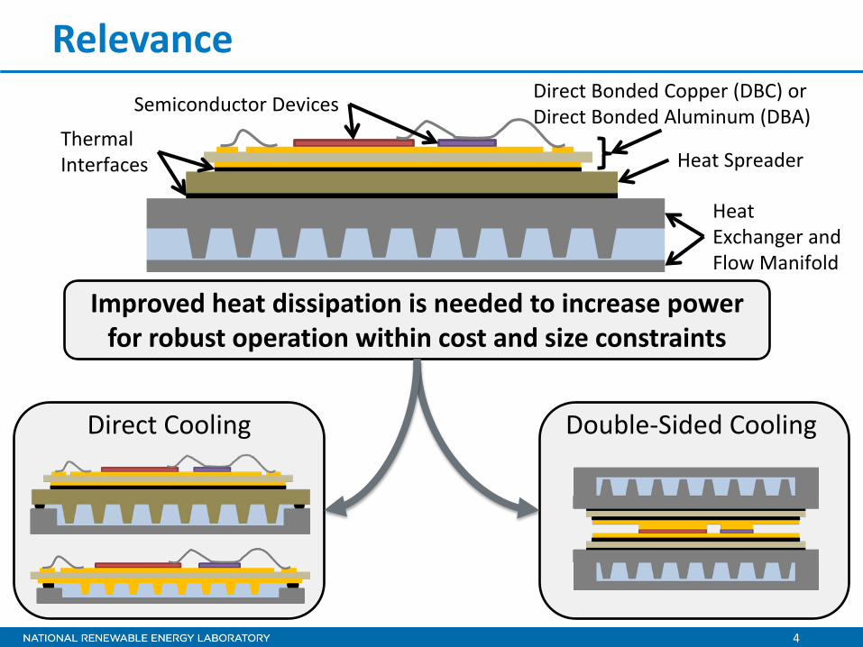
Relevance Semiconductor Devices Direct Bonded Copper (DBC) or
Direct Bonded Aluminum (DBA)
Heat Spreader
Heat Exchanger and Flow Manifold
Thermal Interfaces
Direct Cooling Double-Sided Cooling
Improved heat dissipation is needed to increase power for robust operation within cost and size constraints
5
Objectives
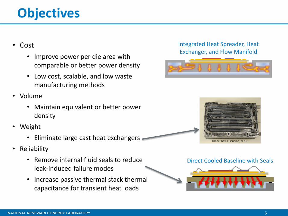
• Cost • Improve power per die area with
comparable or better power density • Low cost, scalable, and low waste
manufacturing methods • Volume
• Maintain equivalent or better power density
• Weight • Eliminate large cast heat exchangers
• Reliability • Remove internal fluid seals to reduce
leak-induced failure modes • Increase passive thermal stack thermal
capacitance for transient heat loads
Integrated Heat Spreader, Heat Exchanger, and Flow Manifold
Credit: Kevin Bennion, NREL
Direct Cooled Baseline with Seals
6
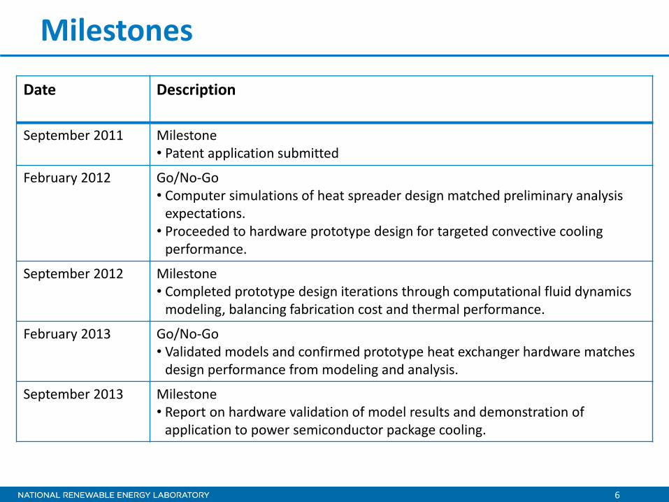
Milestones
Date Description
September 2011 Milestone • Patent application submitted
February 2012 Go/No-Go • Computer simulations of heat spreader design matched preliminary analysis
expectations. • Proceeded to hardware prototype design for targeted convective cooling
performance.
September 2012 Milestone • Completed prototype design iterations through computational fluid dynamics
modeling, balancing fabrication cost and thermal performance.
February 2013 Go/No-Go • Validated models and confirmed prototype heat exchanger hardware matches
design performance from modeling and analysis.
September 2013 Milestone • Report on hardware validation of model results and demonstration of
application to power semiconductor package cooling.

7
Approach/Strategy 2012
Oct
Nov
Dec
2013
Jan
Feb
Mar
Apr
May
Jun
Jul
Aug
Sep
Model Validation • Complete experimental and
hardware test setup • Validate model fluid and
thermal performance
Investigate heat exchanger surface design improvements in collaboration with industry partners
(1) Go/
No-Go
(2) Go/
No-Go
In Progress
Legend
Complete
Model matches test results
Sufficient data for industry transition
Investigate application and redesign for semiconductor package in collaboration with industry and laboratory partners
8
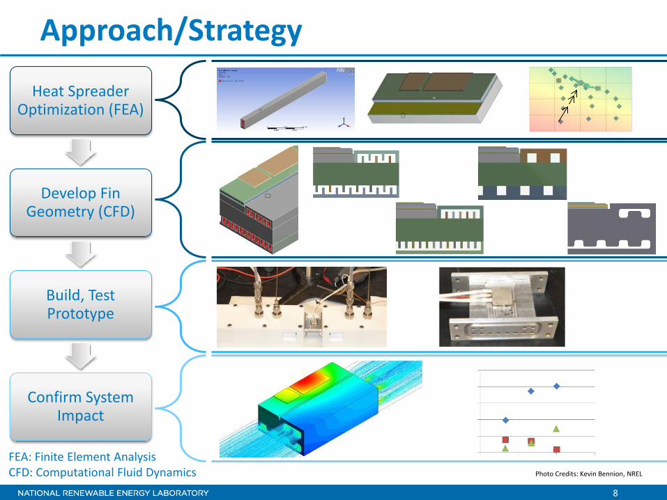
Approach/Strategy
Heat Spreader Optimization (FEA)
Develop Fin Geometry (CFD)
Build, Test Prototype
Confirm System Impact
FEA: Finite Element Analysis CFD: Computational Fluid Dynamics Photo Credits: Kevin Bennion, NREL
9
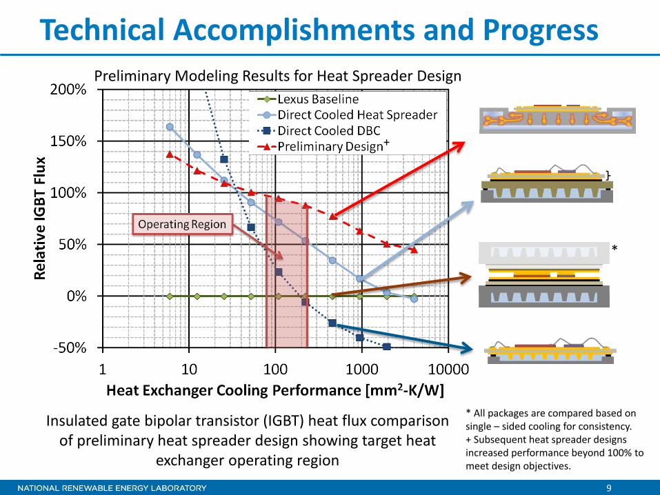
Technical Accomplishments and Progress
Insulated gate bipolar transistor (IGBT) heat flux comparison of preliminary heat spreader design showing target heat
exchanger operating region
* All packages are compared based on single – sided cooling for consistency. + Subsequent heat spreader designs increased performance beyond 100% to meet design objectives.
*
+
Preliminary Modeling Results for Heat Spreader Design
10
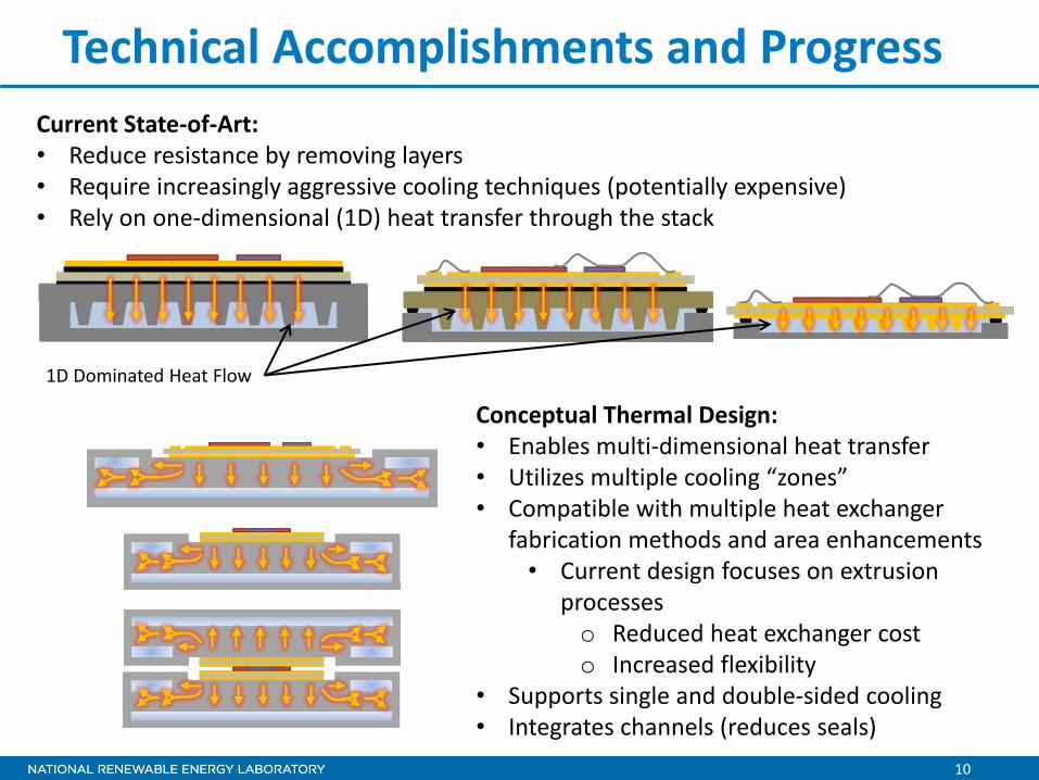
Technical Accomplishments and Progress Current State-of-Art: • Reduce resistance by removing layers • Require increasingly aggressive cooling techniques (potentially expensive) • Rely on one-dimensional (1D) heat transfer through the stack
Conceptual Thermal Design: • Enables multi-dimensional heat transfer • Utilizes multiple cooling “zones” • Compatible with multiple heat exchanger
fabrication methods and area enhancements • Current design focuses on extrusion
processes o Reduced heat exchanger cost o Increased flexibility
• Supports single and double-sided cooling • Integrates channels (reduces seals)
1D Dominated Heat Flow
11
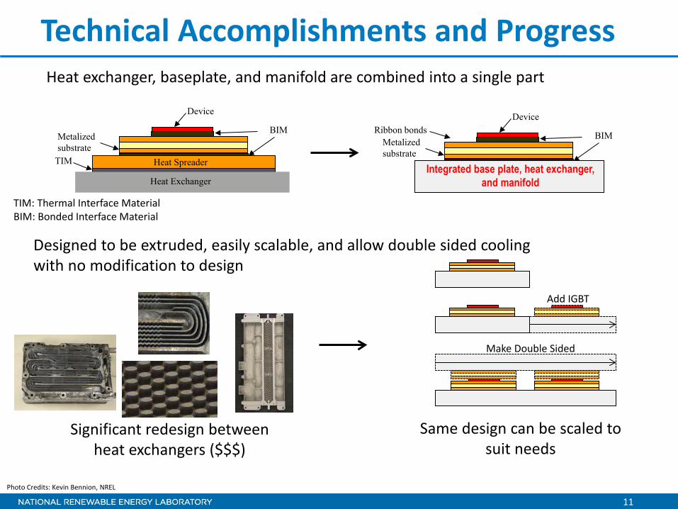
Technical Accomplishments and Progress Heat exchanger, baseplate, and manifold are combined into a single part
Metalized substrate
Device
BIM Ribbon bonds
Integrated base plate, heat exchanger, and manifold
Designed to be extruded, easily scalable, and allow double sided cooling with no modification to design
Add IGBT
Make Double Sided
Metalized substrate
Device
BIM
TIM Heat Spreader
Heat Exchanger
Significant redesign between heat exchangers ($$$)
Same design can be scaled to suit needs
Photo Credits: Kevin Bennion, NREL
TIM: Thermal Interface Material BIM: Bonded Interface Material
12
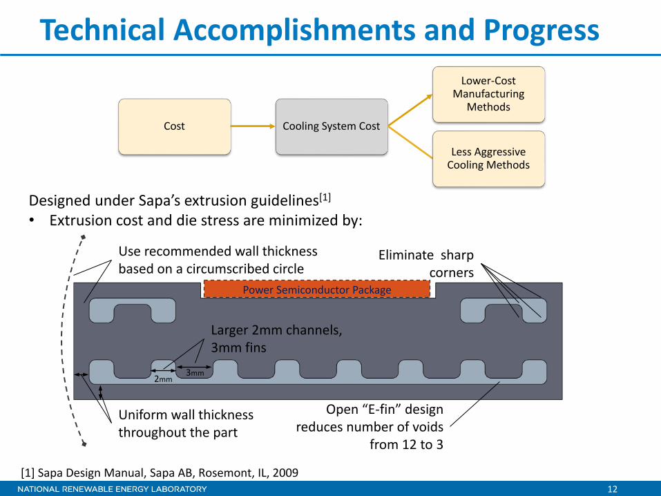
Designed under Sapa’s extrusion guidelines[1]
• Extrusion cost and die stress are minimized by:
Technical Accomplishments and Progress
Cost Cooling System Cost
Lower-Cost Manufacturing
Methods
Less Aggressive Cooling Methods
[1] Sapa Design Manual, Sapa AB, Rosemont, IL, 2009
Use recommended wall thickness based on a circumscribed circle
Uniform wall thickness throughout the part
Larger 2mm channels, 3mm fins
2mm 3mm
Eliminate sharp corners
Open “E-fin” design reduces number of voids
from 12 to 3
Power Semiconductor Package
13
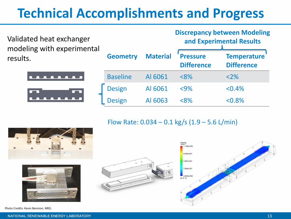
Technical Accomplishments and Progress
Geometry Material Pressure Difference
Temperature Difference
Baseline Al 6061 <8% <2%
Design Al 6061 <9% <0.4%
Design Al 6063 <8% <0.8%
Flow Rate: 0.034 – 0.1 kg/s (1.9 – 5.6 L/min)
Validated heat exchanger modeling with experimental results.
Photo Credits: Kevin Bennion, NREL
Discrepancy between Modeling and Experimental Results
Technical Accomplishments and Progress
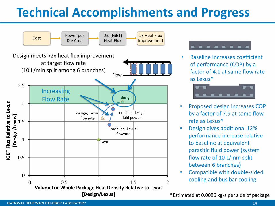
Cost Power per Die Area
Die (IGBT) Heat Flux
2x Heat Flux Improvement
Design meets >2x heat flux improvement at target flow rate
(10 L/min split among 6 branches)
• Baseline increases coefficient of performance (COP) by a factor of 4.1 at same flow rate as Lexus*
• Proposed design increases COP by a factor of 7.9 at same flow rate as Lexus*
• Design gives additional 12% performance increase relative to baseline at equivalent parasitic fluid power (system flow rate of 10 L/min split between 6 branches)
• Compatible with double-sided cooling and bus bar cooling
*Estimated at 0.0086 kg/s per side of package
Increasing Flow Rate
14

15
Technical Accomplishments and Progress
Heat density increased by 34% (Exceeded Objective) over Lexus at target flow rate
(10 L/min split among 6 branches)
Volume Total Heat Density (heat removed per package volume)
Maintain Best-In-Class Performance
Increasing Flow Rate
*Estimated at 0.0086 kg/s per side of package
• Baseline increases coefficient of performance (COP) by a factor of 4.1 at same flow rate as Lexus*
• Proposed design increases COP by a factor of 7.9 at same flow rate as Lexus*
• Design gives additional 12% performance increase relative to baseline at equivalent parasitic fluid power (system flow rate of 10 L/min split between 6 branches)
• Compatible with double-sided cooling and bus bar cooling

16
Collaboration and Coordination
Heat Exchanger Collaboration Partner (Sapa)
Power Semiconductor Packaging Partner Input
Oak Ridge National Laboratory/APEEM Program • Support from benchmarking activities • Ensure thermal design space is appropriate and modeling assumptions are consistent with
other aspects of APEEM research
Plan
Other Government Laboratories
Industry
Model Validation
Investigate heat exchanger surface design improvements
Investigate application and redesign for semiconductor package in collaboration with industry and laboratory partners
17
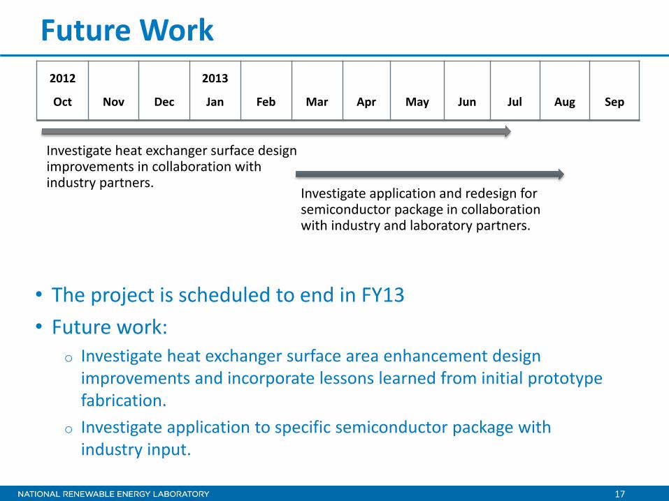
Future Work
• The project is scheduled to end in FY13 • Future work:
o Investigate heat exchanger surface area enhancement design improvements and incorporate lessons learned from initial prototype fabrication.
o Investigate application to specific semiconductor package with industry input.
2012
Oct
Nov
Dec
2013
Jan
Feb
Mar
Apr
May
Jun
Jul
Aug
Sep
Investigate heat exchanger surface design improvements in collaboration with industry partners.
Investigate application and redesign for semiconductor package in collaboration with industry and laboratory partners.
18
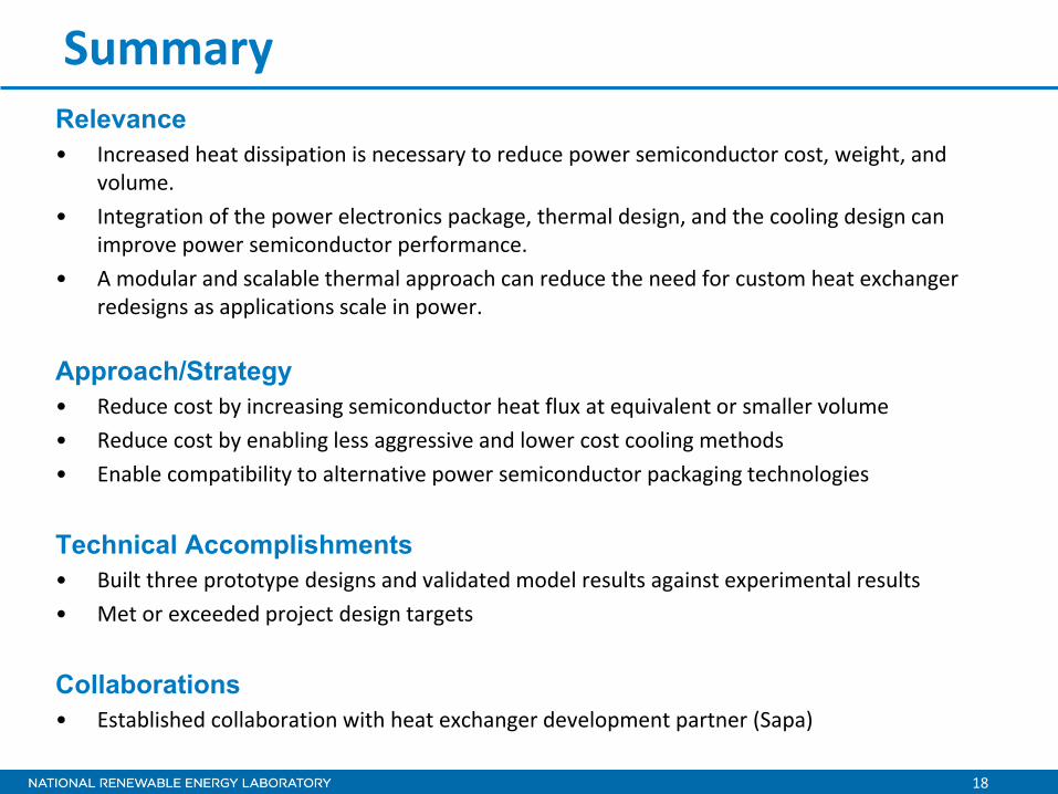
Summary Relevance • Increased heat dissipation is necessary to reduce power semiconductor cost, weight, and
volume. • Integration of the power electronics package, thermal design, and the cooling design can
improve power semiconductor performance. • A modular and scalable thermal approach can reduce the need for custom heat exchanger
redesigns as applications scale in power.
Approach/Strategy • Reduce cost by increasing semiconductor heat flux at equivalent or smaller volume • Reduce cost by enabling less aggressive and lower cost cooling methods • Enable compatibility to alternative power semiconductor packaging technologies
Technical Accomplishments • Built three prototype designs and validated model results against experimental results • Met or exceeded project design targets
Collaborations • Established collaboration with heat exchanger development partner (Sapa)
For more information contact:
Principal Investigator Kevin Bennion [email protected] Phone: (303)-275-4447 APEEM Task Leader:
Sreekant Narumanchi [email protected] Phone: (303)-275-4062
Acknowledgments:
Susan Rogers and Steven Boyd, U.S. Department of Energy Team Members:
Justin Cousineau Jason Lustbader Mark Mihalic


![Heat and Thermal Energy Notes.ppt [Read-Only] - Yolasteeverphysics.yolasite.com/resources/Heat and Thermal Energy Note… · Title: Heat and Thermal Energy Notes.ppt [Read-Only] Author:](https://img.pdfslide.net/doc/110x75/5a8dcaa87f8b9abb068cbdb8/heat-and-thermal-energy-notesppt-read-only-and-thermal-energy-notetitle.jpg)