Embed Size (px)
Citation preview

Liping Guo, Marjukka Eloholma, and Liisa Halonen. 2008. Intelligent road lightingcontrol systems. Espoo, Finland. Helsinki University of Technology, Department ofElectronics, Lighting Unit, Report 50.
© 2008 by authors
Helsinki University of Technology Report 50 Department of Electronics, Lighting Unit Espoo, Finland 2008
Intelligent road lighting control systems
Liping Guo Marjukka Eloholma Liisa Halonen
.
1
Helsinki University of Technology Faculty of Electronics, Communications and Automation Department of Electronics Lighting Unit P.O. Box 3300 FIN-02015 TKK Tel +358 9 451 4971 Fax +358 9 451 4982 Email [email protected] ISBN 978-951-22-9404-6 ISBN 978-951-22-9405-3 (pdf) ISSN 1797-4178 ISSN 1797-4186 (pdf) Espoo, Finland 2008

2
Abbreviations and symbols
AL Lighting class for motor traffic in Tiehallinto (Finnish Road Administration) guidelines of road lighting design
CCT Correlated Colour Temperature
CRI Colour Rendering Index
GPRS General Pocket Radio Service
GSM Global System for Mobile communications
HID High Intensity Discharge
HPS High Pressure Sodium
LDD Luminaire Dirt Depreciation
LLD Lamp Lumen Depreciation
ME Lighting class for motor traffic in CEN standards
MH Metal Halide
MOVE Mesopic Optimization of Visual Efficiency
PWM Pulse-width Modulation
SR Surround Ratio
VI Visibility Index
VL Visibility Level
VT7 Highway No. 7 in Finland
3
Abstract
Currently the road lighting control systems range from very simple to the most modern applications. Intelligent road lighting is a relatively new concept and there are still many open questions, e.g. the definition of control parameters, reliability of communication systems, and the real savings in energy consumption and maintenance costs and so on. The report starts with the architecture of intelligent road lighting control systems and the main characteristics of light sources used in road lighting. Then it focuses on the performance of intelligent road lighting control systems by using examples of two lighting installations in Finland. The differences in maintenance between intelligent and conventional lighting systems are investigated and financial calculation methods are used to evaluate the cost effectiveness of the intelligent road lighting control systems.

4
Table of contents
ABBREVIATIONS AND SYMBOLS ...................................................................................................2
ABSTRACT ............................................................................................................................................3
TABLE OF CONTENTS........................................................................................................................4
1. INTRODUCTION ................................................................................................................................5 2. ARCHITECTURE OF INTELLIGENT ROAD LIGHTING SYSTEMS.........................................................6 3. LIGHT SOURCES IN ROAD LIGHTING................................................................................................8
3.1 Characteristics of HPS lamps and their applicability for dimming ...........................................8 3.2 Characteristics of MH lamps and their applicability for dimming ............................................9
4. EXPERIENCES OF INTELLIGENT ROAD LIGHTING CONTROL SYSTEMS ......................................... 10 4.1 System description.................................................................................................................... 10 4.2 System analysis and discussions............................................................................................... 14
4.2.1 Experiences from luminance monitoring ..........................................................................................14 4.2.2 Experiences from data communication .............................................................................................14
4.3 Road lighting measurements .................................................................................................... 18 5. ROAD LIGHTING MAINTENANCE IN INTELLIGENT ROAD LIGHTING CONTROL SYSTEMS ............. 21 6. FINANCIAL CALCULATIONS ........................................................................................................... 26 7. CONCLUSIONS ................................................................................................................................ 30 REFERENCES...................................................................................................................................... 31

5
1. Introduction
This research work has been carried out at the Lighting Laboratory, Helsinki University of Technology during 2006-2008 as part of the Finnish research project “ValOT”. The objective of the project is to develop the quality, safety and energy efficiency of road lighting through development of intelligent road lighting control and operation of the control system in different traffic and weather conditions. The project also aims to explore the overall optimization of road lighting by taking into consideration the lighting equipment, light sources, road surface and visibility conditions in varying weather conditions. The project is funded by the Finnish Funding Agency for Technology, and Innovation and Finnish Industry.
Energy efficiency is one of the most popular issues in the world and much effort has been devoted to the improvement of energy efficiency and reducing energy consumption. Road and street lighting represents a large amount of energy consumption each year as light intensity is often excessive when traffic density is low [Walraven 2006]. On the other side, some specific situations may occur in which lighting intensity is lower than needed, e.g. in bad weather conditions or special occasions [ILE 2006]. For the purpose of saving energy, in some cases, half the road lamps are switched off at midnight. However, this results in bad uniformity in light distribution and poor visibility. In past decades, there has been significant development in electronics, communication, automation, and computer science. With these new technologies, it might now be possible to adjust the light levels according to real needs.
Currently, the road lighting control systems range from very simple to the most modern applications. Different words are used to describe these lighting control systems, e.g. telemanagement, adaptive, dynamic and intelligent. Telemanagement with networking and automation technology allows for the adjustment of light levels [Walraven 2006]. The light levels with telemanagement lighting control can be adjusted adaptively, dynamically or intelligently. If the light levels of a lighting system are adjusted according to predefined parameters such as time, traffic density, weather conditions etc, the lighting system can be called adaptive or dynamic. An adaptive or dynamic lighting control system can be intelligent when light levels are adjusted real time according to real needs.
An intelligent road lighting control system is defined here as a modern lighting control system based on the technology of computer science, communication, automation, and power electronics, which can automatically collect system information, analyze, deduce and estimate the collected information, and realize the optimum lighting control effect by changing lamp light output real time according to real needs. The main purpose of an intelligent road lighting control system is to save electricity and maintenance costs without negative effects on traffic safety. From the lighting point of view, this means providing the optimum luminance level based on the prevailing traffic and weather conditions.
6
2. Architecture of intelligent road lighting systems
Two essential missions of an intelligent road lighting control system are surveillance and control. Monitoring lamp status can reduce the maintenance cost by reduced routine inspection and repair costs. Control of lamps can lead to energy savings by lowering the lamp power when light levels are excessive. An intelligent road lighting control system consists of a control centre, remote terminal units (also called central controllers), light control units (also called local controllers), ballasts and lamps [Luxmate 2006, Luxicom 2006, Magnetek 2005, Walraven 2006].
The control centre is composed of computers and management software. The main functions of the control centre are collecting and analyzing the information, making decisions as to dimming, sending demands to remote terminal units, and saving the operation information [Luxmate 2006, Luxicom 2006, Magnetek 2005, Walraven 2006]. The control centre is often connected with illuminance/luminance meters and a traffic control centre. This enables it to collect illuminance/luminance information and information about weather conditions and traffic volumes and to compare the information with preset parameters and make decisions as to whether to dim or switch on/off lamps. Remote terminal units are installed in the control cabinets of the road lighting installations. A control cabinet normally contains several lighting contactors, circuit breakers, a timer and/or a photocell and a remote terminal unit. Remote terminal units can collect field information from light control units and send the information to the control centre, receive the commands from the control centre and transmit them to light control units. Thus a remote terminal unit has two communication interfaces. One is to communicate with the control centre and the other is to communicate with light control units. Light control units receive commands from the remote terminal unit and execute the command, and transmit the status information of lamps to the remote terminal unit [Luxmate 2006, Luxicom 2006, Magnetek 2005, Walraven 2006].
Communication is the key issue in an intelligent road lighting control system. Normally, the control centre is far from the remote control unit and lamps. There are several communication solutions that can be used. Wireless communications, such as radio and GSM/GPRS, are possible solutions with high transmission rate and high capability for large-scale long-distance communication [Schoenherr 2003]. Wireless communication, however, results in relatively high operation costs. Wired communication, such as optic fibre and telephone lines, are also possible solutions, depending on the budget. The use of optic fibre is very expensive but it has high capability and transmission rate. The telephone line is an economical solution, but has a low capacity and low transmission rate [Schoenherr 2003].
Between the remote control unit and light control units, radio and a power line carrier are two possible solutions with reasonable costs. Power line communication is economical due to the existing wires, but it is easily affected by interference [Pavlidou 2003]. Radio communication has better immunity to interference but requires antenna and repeaters [RT 2004].

7
The choice of communication systems depends on the specific applications, requirements, and budget. There is only a right solution for the right application, whereas there is no single solution that is better than others in all cases.

8
3. Light sources in road lighting
At present, high intensity discharge (HID) lamps are the most popularly used light sources in road lighting.
The HID lamp family includes high-pressure sodium (HPS), low-pressure sodium (LPS), metal halide (MH), and mercury vapour lamps. Two basic types of high efficacy HID lamps are HPS and MH lamps. HPS lamps are the dominant light sources used in road lighting currently because of long lamp life and high luminous efficacy. MH lamps offer high luminous efficacy and good colour rendering properties. MH lamps compete with HPS lamps in road lighting as the whiter light of MH lamps provides better peripheral visibility at low illumination levels [NLPIP 2005].
3.1 Characteristics of HPS lamps and their applicability for dimming
HPS lamps have their main application area in the field of outdoor lighting, especially on motorways and streets and in tunnels and parks. They are available in the range of 35 W to 1000 W, and efficacy is between 45 and 150 lm/W, depending on size [Simpson 2003]. For road lighting applications, 150 W and higher-wattage HPS lamps are applied most widely. The lamp lives of HPS lamps are between 10,000 and 24,000 hours [Simpson 2003]. Colour rendering ranges from 25 for the standard HPS lamp, to 85, which is the improved colour version [Simpson 2003]. The resonance lines at 589.0 nm play a central role in the spectrum of HPS lamps, resulting in yellowish light [Simpson 2003].
HPS lamps have a negative impedance characteristic, and a device such as an electromagnetic or electronic ballast should be used to limit the current. Electromagnetic ballasts are most popularly used for 150 W and higher wattage HPS lamps at the moment. It is possible to realize step dimming or continuous dimming with electromagnetic ballasts. Constant-voltage autotransformer magnetic ballasts are used mostly for step dimming. When set to the dimmed setting, the circuit includes an additional capacitor, resulting in a fixed reduction in power and light output. Variable voltage transformers, variable reactors and electronic control circuits are used for continuous dimming [NLPIP 1994]. Variable voltage transformers reduce the primary voltage supplied to the ballasts, reducing light output and electrical input. Variable reactors change lamp current without affecting the voltage. Electronic control circuits change the waveform of current and voltage input to the ballasts [NLPIP 1994].
However, electromagnetic ballasts have large size and weight, low efficiency, and sensibility to voltage changes. Electronic ballasts can overcome all these drawbacks [Macio 2002]. Furthermore, electronic ballasts offer more possibilities for lighting control than conventional magnetic ballasts. There are mainly three dimming methods for HPS lamps with electronic ballasts. These are variation of operating voltage of inverter, variation of operating frequency of inverter, and variation of pulse-width of inverter output signal (PWM). Variation of the voltage or frequency is easy to realize, but the colour of light will be affected. PWM is more complicated, but colour of light output will be affected only minimally. Acoustic resonance is the most serious problem

9
for electronic ballasts of HPS lamps. It perturbs the discharge path, causing arc bowing and snaking, flicker, changing in the colour temperature, and, in the worst case, the arc can be extinguished [Macio 2002]. Several solutions to avoid acoustic resonance have been proposed for electronic ballasts; these include high frequency operation (20~200 kHz) in a narrow window free of resonance, extra-high frequency operation in which resonance does not appear, the use of a modulation strategy that modifies the inverter frequency before the acoustic resonance grows, and low frequency operation (around 50~250 Hz) by driving the lamp with a square waveform [Macio 2002]. However, these solutions only work properly with low-wattage HPS lamps. No matter which ballasts are applied, the dimming range is limited for HPS lamps and colour rending starts to shift even at 60% of rated power.
3.2 Characteristics of MH lamps and their applicability for dimming
MH lamps are available in low, mid-range, and high wattages from 35 to 2000 watts. Mid-wattage MH lamps from 175 W to 400 W compete with HPS lamps for road and street lighting applications [NLPIP 2005]. MH lamps provide white light in a variety of correlated colour temperatures (CCT) ranging from 3200 to 5200 K, and are commonly available with a colour-rendering index (CRI) of 65 to 70, but can also have a CRI of 90 or above [NLPIP 2005].
MH lamp arc tubes are made of either quartz or ceramic. Ceramic arc tubes allow higher arc tube temperatures, which result in better efficacy, colour rendering and colour stability. Previously, ceramic tubes were only available in low power ratings, but now they are also commercially available in mid-wattage.
It is possible to dim MH lamps, but the problems are basically the same as with HPS lamps, e.g. limited dimming range and reduced colour rendering. An additional problem with MH lamps is the change in colour temperature in dimming use, resulting in bluish/greenish light [Simpson 2003]. In the family of HID lamps, MH lamps are the most susceptible to changes in the colour characteristics when dimmed [NLPIP 1994].
Several manufacturers offer solid-state electronic ballasts for MH lamps. Manufacturers claim that these ballasts provide better performance in a smaller package, have a high power factor, save more energy, generate less heat, and have lower maintenance costs compared to electromagnetic ballasts [NLPIP 2005]. Two concerns with electronic ballasts that operate at high frequency are acoustic resonance and electromagnetic interference. Some manufacturers are using a low frequency square wave to avoid the problems. These ballasts are more commonly available for lamps below 150 watts. Electromagnetic ballasts are still the most common ballasts used with mid-wattage MH lamps [NLPIP 2005]. It is not recommended to dim mid-wattage MH lamps down to 50% of rated power [Craig 2004].
10
4. Experiences of intelligent road lighting control systems
4.1 System description
In Finland, several intelligent road lighting control systems have been installed in order to get energy savings and reduce maintenance cost. The installations of Ring III and VT7 are introduced in the following.
An intelligent road lighting system was installed on Helsinki Ring III in autumn 2005. The control system has been in use since January 2006. There are altogether 492 luminaires with 600W HPS lamps on the 4 km six-lane road between Lentoasemantie-Tikkurila. The lighting class of Ring III is AL2 with average road surface luminance 1.5 cd/m2 , as shown in Table 1 [Tiehallinto 2006]. The requirements of lighting class AL2 are the same as ME2 in European standards, except for the longitudinal uniformity [EN 13230-2 2003, Tiehallinto 2006].
Table 1 Guidelines of lighting classes for motor traffic [Tiehallinto 2006] Dry conditions Disability glare Lighting of surroundings Class
L in cd/m2
[minimum
maintained]
U0
[minimum]
Ul
[minimum]
TI in %
[maximum]
Surround Ratio
[minimum]
AL1 2,0 0,4 0,6 10 0,5
AL2 1,5 0,4 0,6 10 0,5
AL3 1,0 0,4 0,6 15 0,5
AL4a 1,0 0,4 0,4 15 0,5
AL4b 0,75 0,4 0,4 15 0,5
AL5 0,5 0,4 0,4 15 0,5
Note: L is the average road surface luminance, U0 is the overall uniformity of road surface luminance,
and Ul is the longitudinal uniformity of road surface luminance. TI is the threshold increment.
Another similar lighting control system was installed on Motorway VT7, Helsinki-Porvoo section Västersundom-Harabacka at the end of 2006. This has been in use since January 2007. On VT7, 400W, 250W, and 150W HPS lamps are installed on the 31 km four-lane road. The lighting class of VT7 is AL3 with average road surface luminance 1.0 cd/m2 [Tiehallinto 2006]. AL3 corresponds to ME3 in European standards [EN 13230-2 2003, Tiehallinto 2006]. In order to get more energy savings and adjust the light levels according to real needs, the luminaires in the two driving directions are controlled separately on VT7, since there are substantial differences in traffic density between the two driving directions during rush hours.
The infrastructure of the two control systems is quite similar. The control centre in the traffic centre of Finnish Road Administration in Pasila collects and analyzes the data of
11
traffic flows, road surface luminance information, and road surface conditions, as shown in Figure 1, and makes decisions as to dimming by comparing the data with the predefined parameters. The decisions or commands are transmitted through telephone lines and power line carrier to light control units to dim the lamps. The road surface luminance level is the average value of every ten minutes. The traffic volume is the total number of vehicles per five minutes for all the six lanes of Ring III and for each carriageway (two lanes) of VT7. Road surface conditions used are wet or dry road surface.
a) b) c) Fig. 1. a) The luminance meter measures road surface luminance b) Traffic monitoring system under the road surface gives information about traffic situations
c) Weather stations monitor the road surface conditions (wet, dry)
Electromagnetic ballasts are employed due to their reliability. The controlling method is voltage dimming by triac, as shown in Figure 2. In both installations of Ring III and VT7, HPS lamps are used. The dimming characteristics of HPS lamps are shown in Figure 3. Although different wattages of HPS lamps are used on Ring III and VT7, the dimming characteristics are essentially the same [Philips 2006]. The lamps can be dimmed down to 35% of rated power and 20% of initial luminous flux. In Ring III and VT7 installations, the dimming range is set from 40% to 100% of rated power.
Fig.2. Connection layout [Luxicom 2006]

12
0 %10 %20 %30 %40 %50 %60 %70 %80 %90 %
100 %
1 2 3 4 5 6 7 8 9 10 11 12 13
dimming steps
per
cen
tag
e o
f ra
ted
lum
iou
s fl
ux
per
ceta
ge
of
rate
d p
ow
er
luminous flux % power %
Fig.3. Dimming characteristics of HPS lamps [Philips 2006]
Both on Ring III and VT7, the status of lamps are monitored by the control centre. The control centre can detect a lamp defect as damaged lamp, blinking lamp, and link defect (power line cut), locate the fault lamps and send maintenance workers to fix or replace the fault lamps immediately if they are in critical locations.
The structure and components of the road lighting control systems on Ring III and VT7 are essentially the same, except for the definition of control parameters and the separate control of luminaires in the two directions of VT7. The control parameters of Ring III and VT7 are shown in Tables 2 and 3. The values are defined based on experience of road lighting designers. Road surface luminance values are collected by the luminance meters and used as feedback to finally adjust the light levels. The purpose of monitoring road surface conditions is to avoid decreasing road surface luminance further in wet conditions. However, the measured road surface luminance values in different road surface conditions are not reliable due to communication problems. The information of road surface conditions from the weather stations are not used either due to technical problems. Currently, traffic volume is the only functioning parameter in the lighting control systems of Ring III and VT7.
13
Table 2 Control parameters on Ring III Vehicles
per 5 minutes
Luminance
(cd/m2)
Lamp power
(%)
1 0.75 40
10 0.8 45
20 0.85 50
35 0.95 55
40 1 60
50 1.02 65
60 1.05 70
70 1.1 75
80 1.15 80
90 1.2 85
100 1.3 90
150 1.4 95
170 1.5 100
Note: The number of vehicles per 5 minutes is collected from all six lanes.
Table 3 Control parameters on VT7
Note: The luminaires in two driving directions, from Helsinki to Porvoo and from Porvoo to Helsinki, are
controlled separately according to traffic volume per driving direction. The number of vehicles per 5
minutes is collected for each direction.
According to Table 2, the control system on Ring III is based on continuous dimming with 5% dimming steps, and there is a required minimum luminance value for each dimming level. The minimum luminance is 0.75 cd/m2 when the lamps are dimmed to 40% of rated power. However, based on the dimming characteristics in Figure 3, when the lamps are dimmed to 40% of rated power, the light output is 25% of initial light output. Suppose that the average road surface luminance is 0.75 cd/m2 when lamps are burning at 40% of rated power, the road surface luminance will be as high as 3 cd/m2 when lamps are burning at full power, which is much higher than the requirement of lighting class AL2. The values of luminance requirements given in Table 2 are actually not correct.
In Table 3, the dimming levels on VT7 are based on the dimming characteristics of HPS lamps. The major differences between Ring III and VT7 lie in the number of
Vehicles per 5
minutes
Luminance
(cd/m2)
(dry conditions)
Lamp Power
(%) (dry conditions)
24 or less 0.25 40
25 – 69 0.50 60
70 -99 0.70 80
Over 100 1.00 100

14
dimming levels and in the separate control of luminaires in the two driving directions of VT7. On Ring III, lamp power is adjusted with 5% steps with the traffic volume as defined in Table 2. When the traffic volume is below 100 vehicles per 5 minutes, the lamp power is very sensitive to the change in traffic volume; for example, even a change of 5 vehicles in 5 minutes can result in 5% variation in lamp power. On motorways like Ring III, traffic volume changes all the time and the power of the lamps is consequently adjusted all the time. However, on VT7, there are only four dimming levels. The lamps can operate stably at a particular power level for a relatively long period.
4.2 System analysis and discussions
4.2.1 Experiences from luminance monitoring
Currently, for Ring III and VT7 installations, information of road surface luminance and road surface conditions are not actually used in changing dimming levels, due to technical problems. Traffic volume is the only control parameter that is functioning.
For Ring III, the luminance meters are installed at a height of four meters, attached to a light pole on the side of the road. For VT 7, two luminance meters are installed for each driving direction in order to collect road surface luminance information for each carriageway. However, there have been communication problems between the luminance meters and the control centre on VT7. Additionally, monitoring road surface luminance is very difficult to realize in practice, as many factors may affect real-time luminance measurements, e.g. different weather conditions, disturbances of road profile and vehicles on the road. Ideally, a luminance meter should be mounted at a height of 1.5 m in the middle of a lane to be consistent with the driver’s view of luminances. In practice, it is not realistic to place the luminance meter at this height because it will get dirty very quickly, be exposed to vandalism, and heavy snow may block the its view. It is therefore crucial to find an optimal position for the luminance meter so that luminance measurements are reliable and the maintenance of the luminance meter is easy and economic. So far, there are no guidelines or instructions that specify where and what kind of luminance meters should be used to monitor the road surface luminance in an intelligent road lighting control system. A series of measurements were undertaken in the Lighting Laboratory at Helsinki University of Technology in order to find the optimal position of luminance meters for real-time luminance monitoring, which are presented in a separate work [Guo 2007].
4.2.2 Experiences from data communication
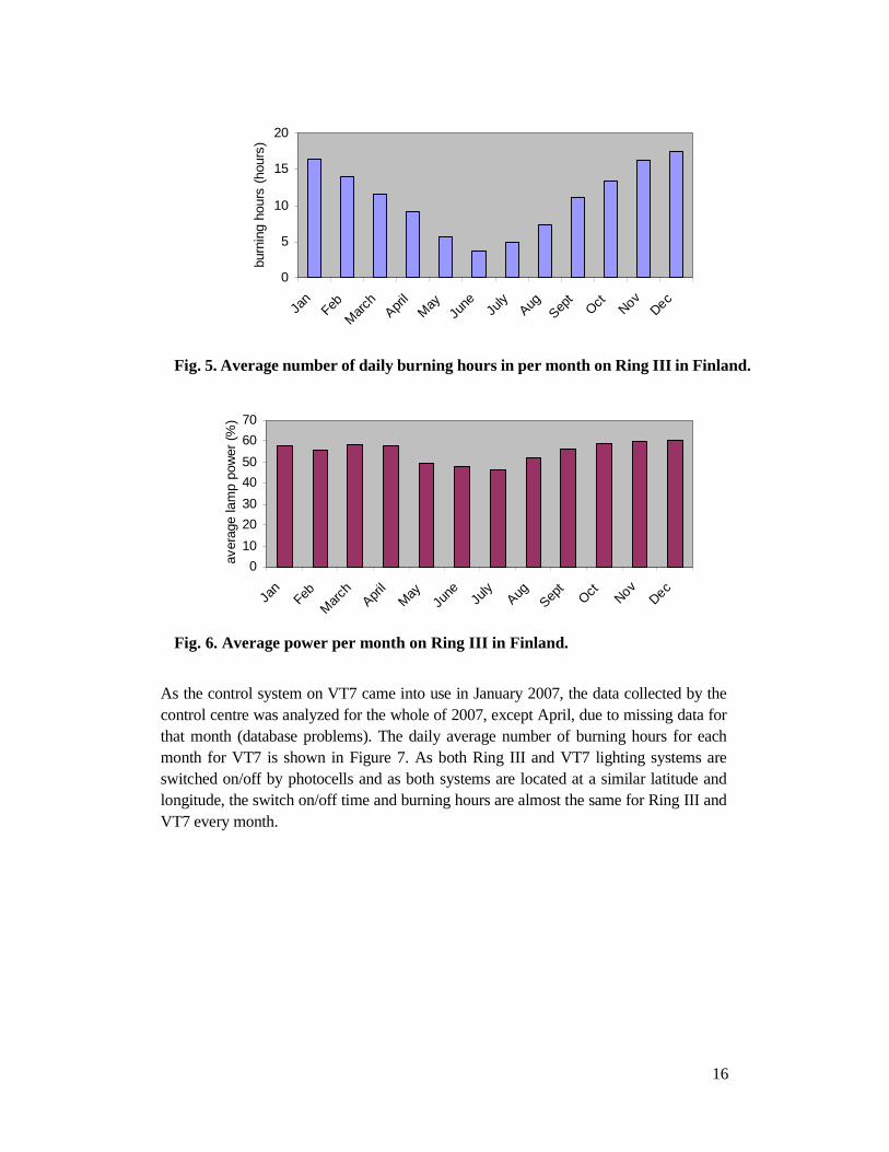
The data from the control centre on Ring III has been analyzed for the whole of 2006. Figure 4 illustrates the average daily energy consumption of each luminaire (600 W HPS lamp) per month from January to December in 2006. It is obvious that the average daily energy consumption in June is the lowest, due to the long duration of daylight. January, November and December have the highest average daily energy consumption because of the darkness in winter time. Figure 5 shows the average number of daily burning hours and Figure 6 illustrates the average lamp power per month. The average number of daily burning hours in June is only 3.7 hours, while in December it is 17.5 hours. The average

15
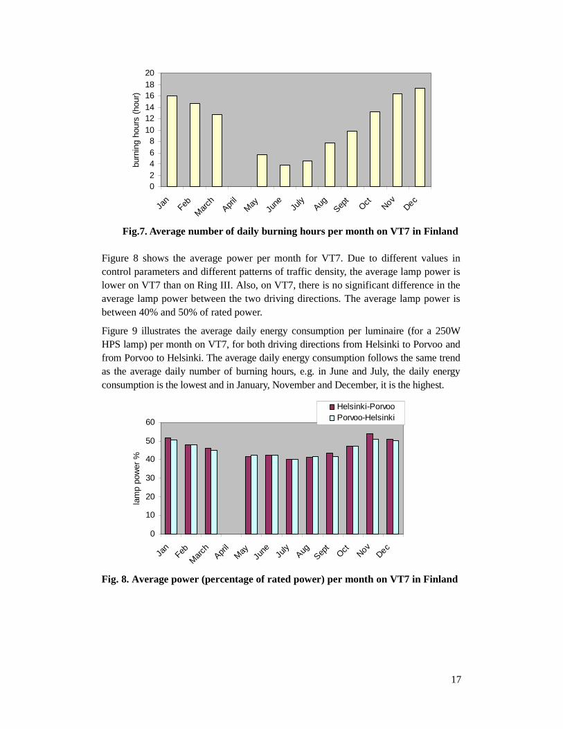
number of daily burning hours follows the same trend as the average daily energy consumption. The annual lamp burning hours are about 3850 calculated from the average number of daily burning hours per month. Figure 6 indicates that the average power per month is mainly between 50% and 60% of rated power. Assuming that the annual average lamp power is 55% of rated power, that the number of annual burning hours is 3850 and that lamp ballasts consume 10% of rated lamp power, the energy saving for a 600W lamp can be calculated as follows. (Since the power consumption of the control units is very small, this part of energy consumption is omitted in the following calculations [Luxicom 2006].)
Total energy consumption for each luminaire if there is no dimming control (lamps are burning at full power in the evenings)
0.6 kW * (1 + 10%) * 3850 h = 2541.0 kWh
Energy savings for each luminaire with the intelligent road lighting control system
0.6 kW * (1 - 55%) * 3850 h = 1039.5 kWh
Energy savings as percentage
1039.5 / 2541.0 = 40.9%
0
1
2
3
4
5
6
7
Jan
Feb
Mar
chApr
ilM
ayJu
ne July
AugSep
tOct Nov
Dec
ener
gy c
onsu
mpt
ion
(kW
h)
Fig. 4. Average daily energy consumption per luminaire per month on Ring III in Finland.
16
0
5
10
15
20
Jan
Feb
Mar
chApr
ilM
ayJu
ne July
AugSep
tOct Nov
Dec
burn
ing
hour
s (h
ours
)
Fig. 5. Average number of daily burning hours in per month on Ring III in Finland.
0
10
20
30
40
50
60
70
Jan
Feb
Mar
chApr
ilM
ayJu
ne July
AugSep
tOct Nov
Dec
aver
age
lam
p po
wer
(%
)
Fig. 6. Average power per month on Ring III in Finland.
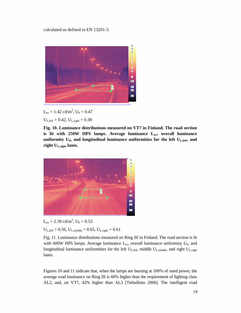
As the control system on VT7 came into use in January 2007, the data collected by the control centre was analyzed for the whole of 2007, except April, due to missing data for that month (database problems). The daily average number of burning hours for each month for VT7 is shown in Figure 7. As both Ring III and VT7 lighting systems are switched on/off by photocells and as both systems are located at a similar latitude and longitude, the switch on/off time and burning hours are almost the same for Ring III and VT7 every month.
17
02468
101214161820
Jan
Feb
Mar
chApr
ilM
ayJu
ne July
AugSep
tOct Nov
Dec
burn
ing
hour
s (h
our)
Fig.7. Average number of daily burning hours per month on VT7 in Finland
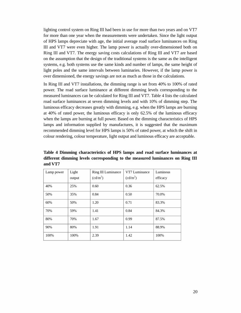
Figure 8 shows the average power per month for VT7. Due to different values in control parameters and different patterns of traffic density, the average lamp power is lower on VT7 than on Ring III. Also, on VT7, there is no significant difference in the average lamp power between the two driving directions. The average lamp power is between 40% and 50% of rated power.
Figure 9 illustrates the average daily energy consumption per luminaire (for a 250W HPS lamp) per month on VT7, for both driving directions from Helsinki to Porvoo and from Porvoo to Helsinki. The average daily energy consumption follows the same trend as the average daily number of burning hours, e.g. in June and July, the daily energy consumption is the lowest and in January, November and December, it is the highest.
0
10
20
30
40
50
60
Jan
Feb
Mar
chApr
ilM
ayJu
ne July
AugSep
tOct Nov
Dec
lam
p po
wer
%
Helsinki-PorvooPorvoo-Helsinki
Fig. 8. Average power (percentage of rated power) per month on VT7 in Finland

18
0
1
1
2
2
3
Jan
Feb
Mar
chApr
ilM
ayJu
ne July
AugSep
tOct Nov
Dec
ener
gy c
onsu
mpt
ion
(kW
h)
Helsinki-Porvoo
Porvoo-Helsinki
Fig. 9. Average daily energy consumption per luminaire (per 250W HPS lamp) per month on VT7 in Finland
The intelligent road lighting systems are so new that there is lack of experience, which has led to cooperation problems between the companies involved in designing the control systems. Furthermore, there have sometimes been communication problems between the control cabinets and the control centre. For example, their have been instances of the control cabinets sending information to the control centre but not receiving commands from the control system. The lamps are switched on/off automatically by the photocells and burn at 100% of rated power if there are communication problems. The information in the control centre, such as the switch on/off times, traffic volumes and road surface conditions, are reliable except for the lamp dimming levels, since the lamps are not dimmed when the control cabinets do not receive the dimming commands. Therefore, the average power and the energy consumption calculations are based on the ideal case when the communication systems have been working properly throughout the whole year. The real savings from electricity are not as much as those in the calculations.
4.3 Road lighting measurements
Road luminance measurements were taken on Ring III and VT7 according to the European standard EN 13201-3, except for the observer locations. On Ring III, the observer took the measurements on a bridge, while, on VT7, the observer was on the side of the road. The measurements were taken in March and April between 11pm and 1am, when the road surface was dry. The lamp power was adjusted to 100% of rated power on both Ring III and VT7 in the measurements. All measurements were made using the imaging luminance meter LMK Mobile Advanced and analyzed by computer program LMK 2000.
Results of the road luminance measurements on Ring III and VT7 are presented in Figures 10 and 11 when the lamps are burning at 100% of rated power and the road surface is dry. For each measurement, the average luminance Lav, overall uniformity U0, and longitudinal uniformities for each lane (UL,left, UL,right, UL,middle) were
19
calculated as defined in EN 13201-3.
Lav = 1.42 cd/m2, U0 = 0.47
UL,left = 0.42, UL,right = 0.38
Fig. 10. Luminance distributions measured on VT7 in Finland. The road section is lit with 250W HPS lamps. Average luminance Lav, overall luminance uniformity U0, and longitudinal luminance uniformities for the left UL,left, and right UL,right lanes.
Lav = 2.39 cd/m2, U0 = 0.53
UL,left = 0.56, UL,middle = 0.65, UL,right = 0.61
Fig. 11. Luminance distributions measured on Ring III in Finland. The road section is lit with 600W HPS lamps. Average luminance Lav, overall luminance uniformity U0, and longitudinal luminance uniformities for the left UL,left, middle UL,middle, and right UL,right lanes.
Figures 10 and 11 indicate that, when the lamps are burning at 100% of rated power, the average road luminance on Ring III is 60% higher than the requirement of lighting class AL2, and, on VT7, 42% higher than AL3 [Tiehallinto 2006]. The intelligent road
20
lighting control system on Ring III had been in use for more than two years and on VT7 for more than one year when the measurements were undertaken. Since the light output of HPS lamps depreciate with age, the initial average road surface luminances on Ring III and VT7 were even higher. The lamp power is actually over-dimensioned both on Ring III and VT7. The energy saving costs calculations of Ring III and VT7 are based on the assumption that the design of the traditional systems is the same as the intelligent systems, e.g. both systems use the same kinds and number of lamps, the same height of light poles and the same intervals between luminaries. However, if the lamp power is over dimensioned, the energy savings are not as much as those in the calculations.
In Ring III and VT7 installations, the dimming range is set from 40% to 100% of rated power. The road surface luminance at different dimming levels corresponding to the measured luminances can be calculated for Ring III and VT7. Table 4 lists the calculated road surface luminances at seven dimming levels and with 10% of dimming step. The luminous efficacy decreases greatly with dimming, e.g. when the HPS lamps are burning at 40% of rated power, the luminous efficacy is only 62.5% of the luminous efficacy when the lamps are burning at full power. Based on the dimming characteristics of HPS lamps and information supplied by manufactures, it is suggested that the maximum recommended dimming level for HPS lamps is 50% of rated power, at which the shift in colour rendering, colour temperature, light output and luminous efficacy are acceptable.
Table 4 Dimming characteristics of HPS lamps and road surface luminances at different dimming levels corresponding to the measured luminances on Ring III and VT7
Lamp power Light
output
Ring III Luminance
(cd/m2)
VT7 Luminance
(cd/m2)
Luminous
efficacy
40% 25% 0.60 0.36 62.5%
50% 35% 0.84 0.50 70.0%
60% 50% 1.20 0.71 83.3%
70% 59% 1.41 0.84 84.3%
80% 70% 1.67 0.99 87.5%
90% 80% 1.91 1.14 88.9%
100% 100% 2.39 1.42 100%

21
5. Road lighting maintenance in intelligent road lighting
control systems
For a lighting system to operate at maximum effectiveness, the maintenance of lighting installations must be considered during the system design process. Once a system has been designed and installed, proper maintenance then becomes essential to the reliability and continued high performance of the roadway lighting system [IESNA DG-4-03 2003].
The maintenance cost forms a significant part in the life cycle cost of road lighting. How to reduce maintenance cost is one of the major considerations for both traditional and intelligent lighting systems. One of the initial motivations for intelligent road lighting is that the maintenance cost is expected to be reduced. Since the lamp status is monitored in the control centre, the system can detect and locate the lamp fault instantly so that the patrol frequency is reduced and the response time is shorter. However, intelligent road lighting control systems are so new that not much maintenance experience has been accumulated so far.
Like traditional lighting systems, the efficiency of intelligent road lighting systems deceases over time due to light losses. There are several factors causing light losses: lamp lumen depreciation, lamp and ballast failure, dirt accumulation on lamps and luminaires, luminaire surface deterioration and damaged light poles. In combination, these factors commonly reduce light output by 20-60% [EPA 1995].
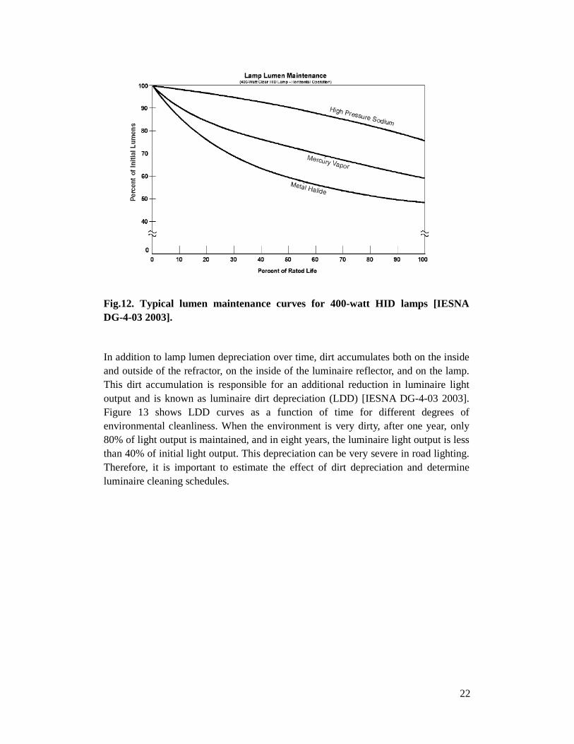
As a lamp ages, the amount of light it produces declines. This change is called lamp lumen depreciation (LLD) and is expressed as a percentage of initial lamp light output [IESNA DG-4-03 2003]. In road lighting applications, HID lamps are widely used. Figure 12 shows the typical lumen maintenance curves for 400 W HID lamps. As shown in Figure 12, HPS lamps have minimal LLD (i.e. they maintain a high percentage of their initial output throughout their useful life). Mercury and MH lamps, however, exhibit significant lumen depreciation. At the end of rated life, only 50% of initial lumens are maintained for MH lamps, while for HPS lamps 80% of initial lumens are maintained.
22
Fig.12. Typical lumen maintenance curves for 400-watt HID lamps [IESNA DG-4-03 2003].
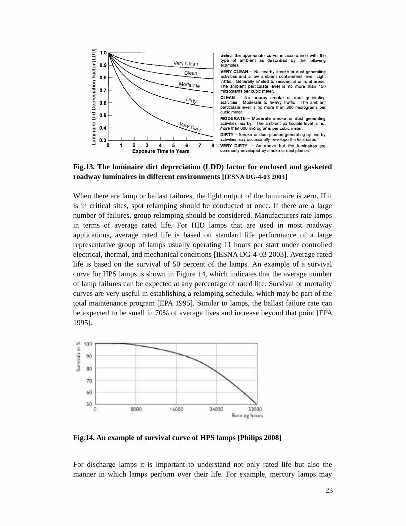
In addition to lamp lumen depreciation over time, dirt accumulates both on the inside and outside of the refractor, on the inside of the luminaire reflector, and on the lamp. This dirt accumulation is responsible for an additional reduction in luminaire light output and is known as luminaire dirt depreciation (LDD) [IESNA DG-4-03 2003]. Figure 13 shows LDD curves as a function of time for different degrees of environmental cleanliness. When the environment is very dirty, after one year, only 80% of light output is maintained, and in eight years, the luminaire light output is less than 40% of initial light output. This depreciation can be very severe in road lighting. Therefore, it is important to estimate the effect of dirt depreciation and determine luminaire cleaning schedules.
23
Fig.13. The luminaire dirt depreciation (LDD) factor for enclosed and gasketed roadway luminaires in different environments [IESNA DG-4-03 2003]
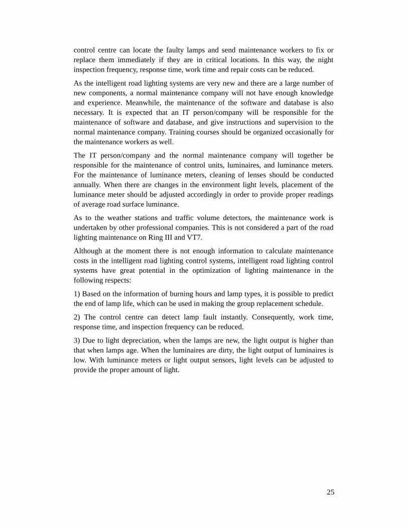
When there are lamp or ballast failures, the light output of the luminaire is zero. If it is in critical sites, spot relamping should be conducted at once. If there are a large number of failures, group relamping should be considered. Manufacturers rate lamps in terms of average rated life. For HID lamps that are used in most roadway applications, average rated life is based on standard life performance of a large representative group of lamps usually operating 11 hours per start under controlled electrical, thermal, and mechanical conditions [IESNA DG-4-03 2003]. Average rated life is based on the survival of 50 percent of the lamps. An example of a survival curve for HPS lamps is shown in Figure 14, which indicates that the average number of lamp failures can be expected at any percentage of rated life. Survival or mortality curves are very useful in establishing a relamping schedule, which may be part of the total maintenance program [EPA 1995]. Similar to lamps, the ballast failure rate can be expected to be small in 70% of average lives and increase beyond that point [EPA 1995].
Fig.14. An example of survival curve of HPS lamps [Philips 2008]
For discharge lamps it is important to understand not only rated life but also the manner in which lamps perform over their life. For example, mercury lamps may

24
continue to burn well beyond their rated life but will then exhibit diminished light output, colour shift, and reduced luminous efficacy [IESNA DG-4-03 2003]. HPS lamps, on the other hand, can be expected to cycle on and off, signalling the end of their life [IESNA DG-4-03 2003]. If cycling lamps are not replaced promptly, ignitor and/or ballast failure could result. This illustrates the need to replace HID lamps before the end of their rated life so that the designed-for illumination levels are maintained and the number of outages is reduced.
Both glass and plastic refractors are used in roadway lighting luminaires. The optical assembly should be checked for irreversible degradation. Exposure to ultraviolet light from the lamp and the sun will cause refractors made from polycarbonate to discolour. This discoloration will reduce the light transmission in some directions. When the luminaire surface turns yellowish, the luminaire should be replaced. If light poles are damaged in an accident, the power connection to the lamps is probably broken as well. It is also important to fix the cables immediately.
Due to the cost of labour, relamping is a particularly expensive component of lighting system maintenance. There are two relamping techniques, spot relamping and group relamping.
Spot relamping is the procedure of replacing a lamp when it has failed [IESNA DG-4-03 2003]. The response times to replace a failed or cycling lamp should be established. Traditionally, owners patrol a lighting system on a scheduled basis and replace lamps as necessary. Many cities and utilities depend upon police reports and citizen call-ins to locate outages [IESNA DG-4-03 2003]. With intelligent road lighting systems, patrol frequency can be reduced since lamp and ballast information are monitored real time and the lamp failure can be detected and alarmed instantly by the control system.
Group relamping is the procedure where all lamps are periodically replaced on a “best time schedule” [IESNA DG-4-03 2003]. The “best time schedule” is when the total cost of installation, energy use, and relamping is at its minimum. For many installations, a group relamp conducted at 2/3 to 3/4 of the rated lamp life provides the mix of minimum acceptable light levels and limited outages yielding the lowest cost [IESNA DG-4-03 2003]. With intelligent road lighting, group relamping may be well planned on the basis of comprehensive information about the lamps, which ensures good lighting quality and driving safety.
In Finland, the Ring III installation has been in use over two years and VT7 for more than one year. The construction company is responsible for the maintenance of the lighting system on Ring III during the first three years, and on VT7 during the first five years. Afterwards, normal maintenance companies will be in charge. At the moment, there is not enough information to calculate the maintenance costs for Ring III and VT7 installations.
Both on Ring III and VT7, the status of lamps are monitored by the control systems. The lamp faults can be detected as damaged lamp, blinking lamp, and link defect (power line cut). The information can be transferred to the control centre, and the
25
control centre can locate the faulty lamps and send maintenance workers to fix or replace them immediately if they are in critical locations. In this way, the night inspection frequency, response time, work time and repair costs can be reduced.
As the intelligent road lighting systems are very new and there are a large number of new components, a normal maintenance company will not have enough knowledge and experience. Meanwhile, the maintenance of the software and database is also necessary. It is expected that an IT person/company will be responsible for the maintenance of software and database, and give instructions and supervision to the normal maintenance company. Training courses should be organized occasionally for the maintenance workers as well.
The IT person/company and the normal maintenance company will together be responsible for the maintenance of control units, luminaires, and luminance meters. For the maintenance of luminance meters, cleaning of lenses should be conducted annually. When there are changes in the environment light levels, placement of the luminance meter should be adjusted accordingly in order to provide proper readings of average road surface luminance.
As to the weather stations and traffic volume detectors, the maintenance work is undertaken by other professional companies. This is not considered a part of the road lighting maintenance on Ring III and VT7.
Although at the moment there is not enough information to calculate maintenance costs in the intelligent road lighting control systems, intelligent road lighting control systems have great potential in the optimization of lighting maintenance in the following respects:
1) Based on the information of burning hours and lamp types, it is possible to predict the end of lamp life, which can be used in making the group replacement schedule.
2) The control centre can detect lamp fault instantly. Consequently, work time, response time, and inspection frequency can be reduced.
3) Due to light depreciation, when the lamps are new, the light output is higher than that when lamps age. When the luminaires are dirty, the light output of luminaires is low. With luminance meters or light output sensors, light levels can be adjusted to provide the proper amount of light.
26
6. Financial calculations
As discussed above, the main purpose of intelligent road lighting control systems is to save energy. In practice, it is important to make economic calculations to make sure the project is cost-efficient. In the road lighting field, payback period and life cycle cost are two calculations methods that are commonly used [E-street 2007]. For intelligent road lighting control systems, the main savings result from energy consumption and maintenance costs. The payback period is then considered as an option for economic calculations to show how many years the installation will pay itself back with the savings. However, the payback period does not properly account for time value of money, risk, inflation, financing or other important considerations. Life cycle cost analysis calculates the cost of a system or a product over its entire life span. It is widely used in new product development studies, project evaluations and management accounting [Wikipedia 2008]. Many of the large road construction projects are based on the method of life cycle costs. This is useful also in road lighting installations [Tiehallinto 2006]. Although significant energy savings can be achieved from intelligent road lighting control systems, the initial construction costs increase significantly.
Life cycle costs include construction, maintenance, energy, demolition, recycling, and final disposal costs. All necessary costs can be calculated from the following formulas [Tiehallinto 2006].
Construction costs
S
kHSHnkHmK svvp
r21 ⋅⋅+⋅+⋅⋅
= (1)
where
Kr is construction costs m number of columns on the cross-section
k1 location factor of the column n number of luminaires on the cross-section
S spacing of the columns (m) Hsv price of the power supply mains (€/road meter)
Hp price of the column and the foundation (€/piece)
Hv price of the luminaire and the first lamp (€/piece)
k2 location factor of the power supply mains
Maintenance costs (costs of lamp replacement and electricity costs)
S
kCmkHnqt
kHnHPnt
Kly
lei
kk
432
31 ⋅⋅+⋅⋅⋅+
⋅⋅+⋅⋅⋅
= (2)
where
Kkk is maintenance costs of the first year t1 annual burning time (h)
t2 life time of the lamp (a) n number of luminaires on the
cross-section
27
Pi power of the luminaire (kW) He price of the energy (€/kWh)
m number of columns on the cross-section C fixed costs (€/column)
k4 maintenance class factor; S spacing of the columns (m)
k3 location factor of the project
Hl price of the group replacement of the lamps (€/piece)
Hly price of the individual replacement of the lamp (€/piece)
q relative number of individual replacement of lamps per year
Life cycle costs
Present value method
Jp
Kp
pKE
tkk
t
rk ⋅+
+⋅+−+=−
)1(
1)1(1 (3)
where
Ek is present value of life cycle costs Kr construction costs
P interest t length of the examination period (years)
Kkk maintenance costs of the first year J residual value
For intelligent road lighting control systems, in the construction costs as shown in Equation (1), the price of luminaires and the first lamp is higher than traditional lighting, and there are extra costs incurred from control units, database, communication system, and luminance/illuminance meters if available. In maintenance costs as shown in Equation (2), the electricity costs should be reduced in theory with intelligent lighting control systems, whereas the lamp replacement costs are not known yet. In Equation (2), extra costs incurred in the maintenance of software and control units are not included. For life cycle costs, there is not enough information to calculate them with Equation (3) at the moment.
Table 5 compares the construction costs of the intelligent road lighting control system of VT7 with a traditional road lighting system. It is assumed that the traditional lighting system has the same numbers and types of luminaries, foundations, columns and earth cables as the intelligent road lighting system.
28
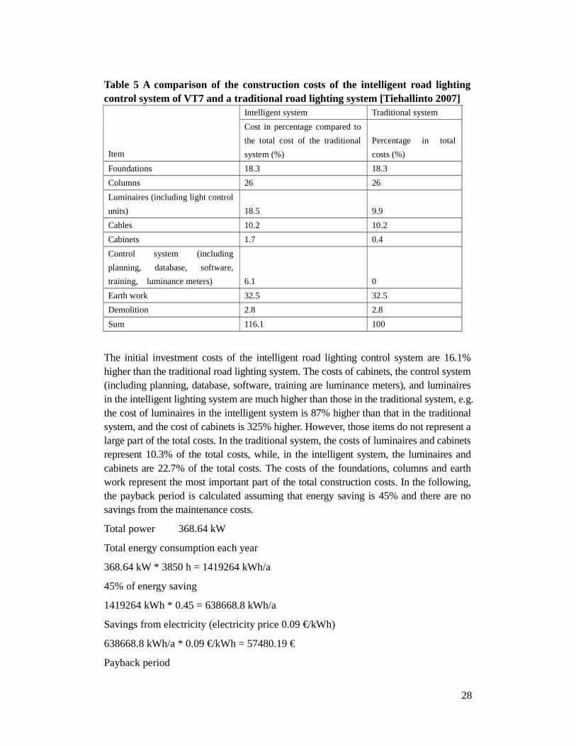
Table 5 A comparison of the construction costs of the intelligent road lighting control system of VT7 and a traditional road lighting system [Tiehallinto 2007]
Intelligent system Traditional system
Item
Cost in percentage compared to
the total cost of the traditional
system (%)
Percentage in total
costs (%)
Foundations 18.3 18.3
Columns 26 26
Luminaires (including light control
units) 18.5 9.9
Cables 10.2 10.2
Cabinets 1.7 0.4
Control system (including
planning, database, software,
training, luminance meters) 6.1 0
Earth work 32.5 32.5
Demolition 2.8 2.8
Sum 116.1 100
The initial investment costs of the intelligent road lighting control system are 16.1% higher than the traditional road lighting system. The costs of cabinets, the control system (including planning, database, software, training are luminance meters), and luminaires in the intelligent lighting system are much higher than those in the traditional system, e.g. the cost of luminaires in the intelligent system is 87% higher than that in the traditional system, and the cost of cabinets is 325% higher. However, those items do not represent a large part of the total costs. In the traditional system, the costs of luminaires and cabinets represent 10.3% of the total costs, while, in the intelligent system, the luminaires and cabinets are 22.7% of the total costs. The costs of the foundations, columns and earth work represent the most important part of the total construction costs. In the following, the payback period is calculated assuming that energy saving is 45% and there are no savings from the maintenance costs.
Total power 368.64 kW
Total energy consumption each year
368.64 kW * 3850 h = 1419264 kWh/a
45% of energy saving
1419264 kWh * 0.45 = 638668.8 kWh/a
Savings from electricity (electricity price 0.09 €/kWh)
638668.8 kWh/a * 0.09 €/kWh = 57480.19 €
Payback period

29
difference in construction costs / savings from electricity ≈ 7 years
In the payback period calculations, 0.09 €/kWh is used as the price of electricity. If the electricity price is lower or the energy saving is less, the payback period will be longer and vice versa. In the calculations, in case of no savings from maintenance costs, the installation can pay itself back in seven years with savings from electricity, although the construction cost of the intelligent road lighting system is 16% higher than the traditional lighting system.

30
7. Conclusions
This work focused on the performance of intelligent road lighting control systems by using the examples of two installations in Finland, Ring III and VT7.
In the two examples of intelligent lighting control systems in Finland, there have been problems in the definition of control parameters and reliability of the communication systems. In the ideal case when there is no communication problem, the average lamp power should be around 50% to 60% of rated power on Ring III and 40% to 50% of rated power on VT7. In summer time during June and July, the number of lamp burning hours is the least and average daily energy consumption is the lowest. In winter time during January, November and December the lamp burning hours are greatest in number and average daily energy consumption is the highest.
On Ring III, lamp power is adjusted in 5% steps according to the traffic volume, which may result in changing lamp power all the time, whereas, on VT7, there are only four dimming levels and the lamps can operate stably at a particular power level for a relatively long period. So continuous dimming as on Ring III is not suggested.
Based on the dimming characteristics of HPS lamps and results of road lighting measurements, it can be calculated that the lamp power is over dimensioned on both Ring III and VT7.
It was expected that both energy costs and maintenance costs would decrease in intelligent road lighting control systems because of reduced lamp power and instant lamp fault reporting. However, the real energy savings are not as much as the energy savings calculations due to communication problems and over-dimensioning of lamp power on both Ring III and VT7. So far, there is not enough information to calculate maintenance costs of the existing installations of Ring III and VT7.
A comparison of the construction costs was made between the intelligent road lighting control system of VT7 and a traditional road lighting system. The initial investment costs of the intelligent road lighting control system are 16.1% higher than the traditional road lighting system. The costs of cabinets, the control system, and luminaires in the intelligent lighting system are much higher than those in the traditional system. However, those items do not represent a major part of the total costs. The costs of foundations, columns and earth work represent the most important part of the total construction costs. If 45% energy savings could be achieved, the pay back period is seven years, even though there are no savings from maintenance costs.
So far, although intelligent road lighting systems with real-time control may provide proper light levels based on real-time information, the benefits are compromised by complexity of the systems, unreliable performance and higher investment. The optimal solution of road lighting control systems should be economic, simple and reliable, but may not be intelligent.

31
References
Craig DiLouie, 2004, Dimming HID Lamps, Lighting Controls Association. EN 13201-2, European Standard, 2003 Road lighting – Part 2: Performance requirements, Publication 269-2003, Ref. No. EN 13201-2:2003 E. EPA (United States Environmental Protection Agency) 430-B-95-009, 1995 January, Lighting maintenance, EPA’s Green lights Program. E-street Initiative Work Package 5.1, June 25, 2007, Guide for energy efficient intelligent outdoor lighting solutions. IESNA DG-4-03, 2003, Design guide for roadway lighting maintenance, Illumination Society of North America. ILE, Institution of lighting engineers, 2006, Technical report 27-code of practice for variable lighting levels for highways. Guo Liping, Eloholma Marjukka, Halonen Liisa, 2007 Vol. 9, Luminance monitoring and optimization of luminance metering in intelligent road lighting control systems, Ingineria Iluminatului,. Luxicom, 2006, road lighting control system demonstration, technical documentation. Luxmate, 2006, OLC (outdoor lighting control) system specifications, 2006. Magnetek HIQ grid-i.Illumination, 2005 Jan, practical monitoring and control of street lighting using power line modem technology. Macio A. Co., Cassius Z. Renende, Domingos S.L. Simonetti, Jose L.F. Vieira, 2002, Microcontrolled electronic gear for HID lamps—comparisons with electromagnetic ballast, IEEE. NLPIP (National Lighting Product Information Program), Lighting answers, 1994 Sep, Vol. 1, No. 4, Dimming systems for High-intensity discharge lamps. NLPIP (National Lighting Product Information Program), Lighting answers, revised 2005 March, 2003 Jan, Vol.7, Issue 1, Mid-wattage metal halide lamp. Pavlidou Niovi, Vinck Han A.J., Yazdani Javad, Honary Bahram, 2003 April, powerline communications: state of the art and future trends, IEEE communication magazine.

32
Philips lighting technical documents, 2006. Philips product catalog, 2008. Royce Thompson (RT), 2004, radio frequency monitoring. Schoenherr Scott, 2003, Wireless technologies for distribution automation, IEEE. Simpson Robert S., 2003, Lighting control technology and applications, Focus press, pp130-138. Tiehallinto (Finnish road administration), 2006, Tievalaistuksen suunnittelu (Road lighting design), Helsinki. Tiehallinto (Finnish road administration), Statistics from Tiehallinto, 2007. Walraven Henk, Echelon As, 2006 July, E-street WP2 Final report--Market assessment and review of energy savings. Wikipedia, 2008, http://en.wikipedia.org/wiki/Main_Page.