Embed Size (px)
Citation preview

Ashghal – Pavement Design Guidelines
PWA IAN 016 Rev 3 Page 1 September 2013
ASHGHAL
Interim Advice Note No. 016
Pavement Design Guidelines
Revision No. 3
EXW-GENL-0000-PE-KBR-IP-00016
ADVICE This Interim Advice Note includes following Pavement Design Guidelines as set out in Attachment A. This IAN provides sufficient guidance to design engineers, consultants and contractors with regard to the design of road pavement constructed as part of the Expressway Programme. It also provides a guide for the professional staff through the pavement design process and the contents of pavement design report and other related submissions. This Interim Advice Note shall take immediate effect and supersedes:
EXW-GENL-0000-PE-KBR-RP-00179 –IAN 016 - Rev 2, Pavement Design Guidelines issued on 26 July 2012.
A1 30 September 2013 Issued for All Relevant Infrastructure Projects AS AM MG
R3 9 September 2013 Major amendment AS AM MG
R2 26 July 2012 Minor Amendment AS AB MG
R1 24 June 2012 Minor Amendment AS AB MG
R0 11 June 2012 Initial Issue AS AB MG
Rev Date Reason For Issue Author Chk App

Ashghal – Pavement Design Guidelines
PWA IAN 016 Rev 3 Page 2 September 2013
Contents
1. Foreword 3
2. Ashghal Interim Advice Note (IAN) – Feedback Form 4
3. Introduction 5
4. Withdrawn / Amended Standard 5
5. Implementation 5
6. Disclaimer 5
Attachment A – Pavement Design Guidelines 6

Ashghal – Pavement Design Guidelines
PWA IAN 016 Rev 3 Page 3 September 2013
1. Foreword 1.1 Interim Advice Notes (IANs) may be issued by Ashghal from time to time. They define
specific requirements for works on Ashghal projects only, subject to any specific implementation instructions contained within each IAN.
1.2 Whilst IANs shall be read in conjunction with the Qatar Highway Design Manual (QHDM), the Qatar Traffic Manual (QTM) and the Qatar Construction Specifications (QCS), and may incorporate amendments or additions to these documents, they are not official updates to the QHDM, QTM, QCS or any other standards.
1.3 Ashghal directs which IANs shall be applied to its projects on a case by case basis. Where it is agreed that the guidance contained within a particular IAN is not to be incorporated on a particular project (e.g. physical constraints make implementation prohibitive in terms of land use, cost impact or time delay), a departure from standard shall be applied for by the relevant Consultant / Contractor.
1.4 IANs are generally based on international standards and industry best practice and may include modifications to such standards in order to suit Qatar conditions. Their purpose is to fill gaps in existing Qatar standards where relevant guidance is missing and/or provide higher standards in line with current, international best practice.
1.5 The IANs specify Ashghal’s requirements in the interim until such time as the current Qatar standards (such as QHDM, QTM, etc.) are updated. These requirements may be incorporated into future updates of the QHDM, QTM or QCS, however this cannot be guaranteed. Therefore, third parties who are not engaged on Ashghal projects make use of Ashghal IANs at their own risk.
1.6 All IANs are owned, controlled and updated as necessary by Ashghal. All technical queries relating to IANs should be directed to Ashghal’s Manager of the Design Department, Infrastructure Affairs.
Signed on behalf of Design Department:
____________________________________________________
Abdulla Ahin A A Mohd
Acting Manager of Roads & Drainage Networks Design
Design Management (Roads Section) Public Works Authority
Tel: 44950653 Fax: 44950666 P.O.Box 22188 Doha - Qatar Email:[email protected] http://www.ashghal.gov.qa
Ashghal – Pavement Design Guidelines
PWA IAN 016 Rev 3 Page 4 September 2013
2. Ashghal Interim Advice Note (IAN) – Feedback Form
Ashghal IANs represent the product of consideration of international standards and best practice against what would work most appropriately for Qatar. However, it is possible that not all issues have been considered, or that there are errors or inconsistencies in an IAN.
If you identify any such issues, it would be appreciated if you could let us know so that amendments can be incorporated into the next revision. Similarly, we would be pleased to receive any general comments you may wish to make. Please use the form below for noting any items that you wish to raise.
Please complete all fields necessary to identify the relevant item
IAN title:
IAN number: Appendix letter:
Page number: Table number:
Paragraph number: Figure number:
Description comment: Please continue on a separate sheet if required:
Your name and contact details (optional):
Name: Telephone:
Organisation: Email:
Position: Address:
Please email the completed form to:
Abdulla Ahin AA Mohd Acting Manager of Roads and Drainage Networks Design Design Management (Roads Section) Public Works Authority [email protected]
We cannot acknowledge every response, but we thank you for contributions. Those contributions which bring new issues to our attention will ensure that the IANs will continue to assist in improving quality on Ashghal’s infrastructure projects.

Ashghal – Pavement Design Guidelines
PWA IAN 016 Rev 3 Page 5 September 2013
3. Introduction 3.1 This Interim Advice Note takes immediate effect and shall be read in conjunction with:
QCS 2010- Qatar Construction Specification -2010
IAN 011- Cycleway Design Guideline
IAN 021- Cycleways and Footways Pavement Design Guidelines
IAN 019- Amendment to QCS 2010
IAN 029- Pavement Standard Detail Drawings
This IAN shall apply to pavement construction on Ashghal’s Expressway projects.
4. Withdrawn / Amended Standard 4.1 This Interim Advice Note shall take immediate effect and supersedes:
EXW-GENL-0000-PE-KBR-RP-00179 –IAN 016 - Rev 2, Pavement Design Guidelines issued on 26 July 2012.
5. Implementation 5.1 This IAN shall be implemented with immediate effect on projects as follows:
5.2.1 All Ashghal Expressway projects in design stage 5.2.2 All Ashghal Expressway projects in tender stage
5.3 Ashghal’s Expressway projects in construction stage shall be reviewed by the Supervision
Consultant and Contractor and the implications of adoption of this Interim Advice Note discussed with the respective Ashghal Project Manager. This shall include an assessment on the current design to determine whether it complies with this Interim Advice Note and the practicalities of modifying the design and construction in order to achieve compliance.
5.4 Following implementation of actions under clause 4.2 for projects already under construction, where a significant portion of construction and procurement has already occurred and/or design or construction modification are not practicable the Consultant/contractor must seek direction from the Engineer for the parts of the works for which departures from this IAN may apply.
5.5 If in doubt, Consultants / Contractors should seek guidance from their respective Ashghal Project Manager or designated Programme Management Consultant (PMC) on a scheme specific basis.
6. Disclaimer 6.1 This Interim Advice Note and its recommendations or directions have been provided for
application on Ashghal’s Expressway projects within Qatar only and they are not warranted as suitable for use on other roads, highways or infrastructure within Qatar or elsewhere. Should any third party, consultant or contractor chose to adopt this Interim Advice Note for purposes other than Ashghal’s Expressway projects they shall do so at their own risk.

Ashghal – Pavement Design Guidelines
PWA IAN 016 Rev 3 Page 6 September 2013
Attachment A – Pavement Design Guidelines

Ashghal – Pavement Design Guidelines
PWA IAN 016 Rev 3 Page 7 September 2013
Attachment A – Pavement Design Guidelines – Contents:
1. Application and Objectives ........................................................ 9
2. Implementation ......................................................................... 10
3. Expressway Pavement Design ................................................ 10
3.1. Design Methods 10
3.2. Road Classification System in Qatar 11
3.3. Pavement Design Inputs for AASHTO Design Method 11
3.3.1. Pavement Serviceability ............................................................. 12 3.3.2. Reliability .................................................................................... 12 3.3.3. Standard Deviation ..................................................................... 12 3.3.4. Layers coefficients (ai) ................................................................ 12 3.3.5. Layers Drainage Coefficients (mi) ............................................... 13
3.4. Pavement Design Inputs for Mechanistic approach 14
3.4.1. Materials Characterization .......................................................... 14 3.5. General Guidelines for Expressway 17
3.6. Perpetual Pavement 18
3.7. Design Variables 19
3.8. Design approaches and acceptance 20
3.9. Pavement Design Life 20
3.10. Special Provisions 21
3.10.1. Pavement Constructed in High Ground Water Areas .................. 21 3.11. Value Engineering 21
4. Pavement Design Submittal ..................................................... 23
5. Reference documents .............................................................. 23
6. Figures ...................................................................................... 23
6.1. Perpetual Pavement without Cement Bound Material - CBM 24
6.2. Perpetual Pavement with Cement Bound Material -CBM 24
6.3. Perpetual Pavement with Cement Bound Material - CBM and Crushed Aggregate Subbase 25
6.4. Perpetual Pavement with Bitumen Bound Material – BBM 25
6.5. Perpetual Pavement with Crushed Aggregate 26
Appendix A – Traffic ...................................................................................................... 27
A.1 Design Traffic Calculations 27
A.2 Direction Distribution Considerations 28
A.3 Lane Distribution Considerations 28
A.4 Traffic Growth 29
A.5 Cumulative Growth Factor 30
A.6 Equivalent Single Axle Load Factors 30
A.7 Determination of the ESALs per day per direction 31
A.8 Cumulative design standard axles 31
A.9 Traffic inputs guidelines, assumptions and calculations 31
A.10 Standard Axle Load 32
A.11 Axle Load Limits 33
A.12 Determination of Cumulative Axles 33
Appendix B – Geotechnical Considerations ................................................................ 34
B.1 Subgrade Design CBR 35
B.2 Subgrade Modulus (Resilient Modulus) 35
Ashghal – Pavement Design Guidelines
PWA IAN 016 Rev 3 Page 8 September 2013
B.3 Modulus back calculated from Deflection 37
B.4 Capping Layer requirements 37
B.5 Approximation of CBM modulus from Unconfined Compressive Strength UCS 37
B.6 Practical guidelines in pavement design 38
Appendix C – Materials .................................................................................................. 39
C.1 Characteristics 39
C.2 Minimum Pavement layers thickness 40
C.3 Pavement layer extent 41
Appendix D – Employer’s Minimum Requirements for Design and Build (D&B) Projects ........................................................................................................................... 42

Ashghal – Pavement Design Guidelines
PWA IAN 016 Rev 3 Page 9 September 2013
1. Application and Objectives The purpose of this document is to guide the pavement design engineers working within expressway program, consultants, contractors and other professional staff through the pavement design process. The guide has been prepared based on the best available practices and the pavement design knowledge accumulated over recent years. It is generally in accordance with the AASHTO “Guide for Design of Pavement Structures – 1993”, but reference has been made to other pavement design approaches and manuals, in particular where pavement design case is not covered in AASHTO pavement design manual. This design standard provides supplementary design guides for Expressway that are designed and constructed on the Doha Expressway programme. This supplementary IAN 016 must be read in conjunction with:
QCS 2010- Qatar Construction Specification-2010
IAN 011- Cycleway Design Guideline
IAN 021- Cycleways and Footways Pavement design Guidelines
IAN 019- Amendment to QCS 2010
IAN 029- Pavement Standard Detail Drawings
In the event of conflicts between these documents, this IAN 016 shall take precedence with respect to expressway pavements. It is intended that the recommendation in this guideline are followed on all Doha Expressway projects unless otherwise directed by the Engineer.
When documenting the design, project specific specifications and drawings for a traditional design, bid and build contract (DBB), the designer shall consider the applicability of the recommendations in this guideline to the particular project and advise Ashghal accordingly.
Similarly when a design for a design and build contract (D&B) is being documented, the recommendations in these guidelines shall be adopted unless otherwise approved by the Engineer. Also in a D&B contract words within this IAN 016 such as “should”, “desirable”, and “recommended”, shall mean “must” or “shall” unless otherwise notified by the Engineer (Ashghal). The main objectives of this guide are:
1. To provide guidance on how to select the most appropriate pavement structure by various design methods, both empirical and mechanistic, and then determine the most economical pavement design that is capable of performing well under traffic loading and environmental conditions without major failure of any segment of the road.
2. To describe methods of data collection and determination of the main design inputs such as traffic loading, existing surface and subsurface conditions and materials to be used in the pavement structure.
3. To describe the method used to estimate the design traffic volumes, percentages of heavy vehicles, load distribution on vehicles axles, and finally the design traffic loading, which should also address the loads due to construction activities in Doha over the next 10 years for that Project.
4. To list the field and laboratory tests and content of the geotechnical testing report required for pavement design.

Ashghal – Pavement Design Guidelines
PWA IAN 016 Rev 3 Page 10 September 2013
5. To identify characteristics of materials required in the determination of the
thickness of the pavement structure.
6. To list the contents of the pavement design submittal at the various stages of each project.
2. Implementation This IAN is to be used with immediate effect for the design the pavement of all New/Reconstructed expressway projects. This includes:
All Expressway projects in Design Stage All Expressway projects in Tender Stage
Where projects are in construction or final detail design, the impacts of this and related IANs are to be assesses by the designer, construction project supervising consultant and the Expressway Project Management Consultant (PMC). If for a significant practical reason, a part of this IAN is not achievable in construction, the particularly item and location where the particular condition of IAN cannot be applied must be approved by the Engineer as a departure from the design standard or specifications.
3. Expressway Pavement Design
3.1. Design Methods
Case 1: Design Traffic <50million ESALs For pavement subjected to a traffic loading less than 50million ESALs over the design period, the Design Consultant is to design the pavement using both empirical and mechanistic procedures (empirical/mechanistic), and then compare it against the typical cross sections included in Qatar Highway Design Manual (QHDM). Case 2: Design Traffic >50million ESALs For roads subjected to heavy traffic loading (design traffic >50million ESALs), the designer shall use the following approaches to design the pavement of roads in State of Qatar:
- AASHTO Pavement Design Method, 1993 (2002 if calibrated) - Mechanistic Pavement Design Method, (CIRCLY or any equivalent
software is recommended) In both cases, the designer shall adopt the pavement structure with the greater pavement thickness that caters for the requirements of fatigue and rutting modes of failure. Case 3: In cases where traffic loads exceeds 50millions ESALs and with low reliability in predicting traffic, Perpetual Pavement (PP) with Polymers in the upper layers shall be considered. The above mechanistic design approach shall be used to determine the thickness of different layers.
In the above three cases, the PG 76-10, S, H, V and E bitumen in the upper surface layers shall be considered according to the arrangements described in the Employer’s Requirement in Appendix D. The submission of the pavement design report shall be as described in the following steps (Figure D1, Appendix D): 1. Upon the project initiation/award to Design Consultant, the consultant shall be issued
with the necessary general information and plans.

Ashghal – Pavement Design Guidelines
PWA IAN 016 Rev 3 Page 11 September 2013
2. The Design Consultant shall meet with KBR pavement design engineer to agree on methodology and schedule for the pavement design method and its subsequent submittal.
3. The consultant shall collect and analyse all data required for pavement design i.e. projects layouts, traffic, geotechnical report and all other relevant documents.
4. The designer may use and consider more than one alternative or approach, other than the recommended method outlined in this document, to calculate the design traffic loading or allowable number of repetitions and the service life offered by the proposed design.
5. The Consultant shall include in his submission a summary description of the
alternative approaches used in the calculations.
3.2. Road Classification System in Qatar Qatar Highway Design manual (QHDM) relates many highway design standards to the functional Road Hierarchy Classification. This indicates that the Road Hierarchy is being used as a framework for the provision of guidance and standards relating to highway design. Design parameters refer to the road class may include:
1. Design speed and horizontal alignment 2. Right of way and Cross section 3. Lighting system 4. Vertical alignment 5. Pavement design
Road classification system outlined in QHDM version 1997 has been subjected to a thorough review and modification. The new road classification system adopted currently in Qatar is shown below in Figure 1.
Figure 1: New Road Classification System in Qatar
3.3. Pavement Design Inputs for AASHTO Design Method AASHTO pavement design is an empirical method widely used in many countries around the world including more than 18 road agencies in USA. The following sections provide brief guidelines on inputs values to be used in pavement design of heavily trafficked roads (primary roads), using AASHTO method.
Ashghal – Pavement Design Guidelines
PWA IAN 016 Rev 3 Page 12 September 2013
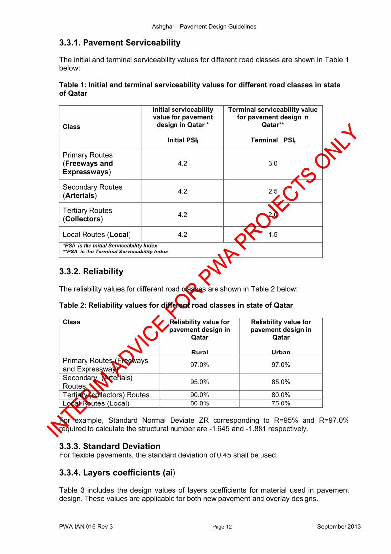
3.3.1. Pavement Serviceability
The initial and terminal serviceability values for different road classes are shown in Table 1 below: Table 1: Initial and terminal serviceability values for different road classes in state of Qatar
Class
Initial serviceability value for pavement
design in Qatar *
Initial PSIi
Terminal serviceability value for pavement design in
Qatar**
Terminal PSIt
Primary Routes (Freeways and Expressways)
4.2 3.0
Secondary Routes (Arterials)
4.2 2.5
Tertiary Routes (Collectors)
4.2 2.0
Local Routes (Local) 4.2 1.5
*PSIi is the Initial Serviceability Index **PSIt is the Terminal Serviceability Index
3.3.2. Reliability
The reliability values for different road classes are shown in Table 2 below:
Table 2: Reliability values for different road classes in state of Qatar
Class Reliability value for pavement design in
Qatar
Rural
Reliability value for pavement design in
Qatar
Urban
Primary Routes (Freeways and Expressway)
97.0% 97.0%
Secondary (Arterials) Routes
95.0% 85.0%
Tertiary (collectors) Routes 90.0% 80.0%
Local Routes (Local) 80.0% 75.0%
For example, Standard Normal Deviate ZR corresponding to R=95% and R=97.0% required to calculate the structural number are -1.645 and -1.881 respectively.
3.3.3. Standard Deviation For flexible pavements, the standard deviation of 0.45 shall be used.
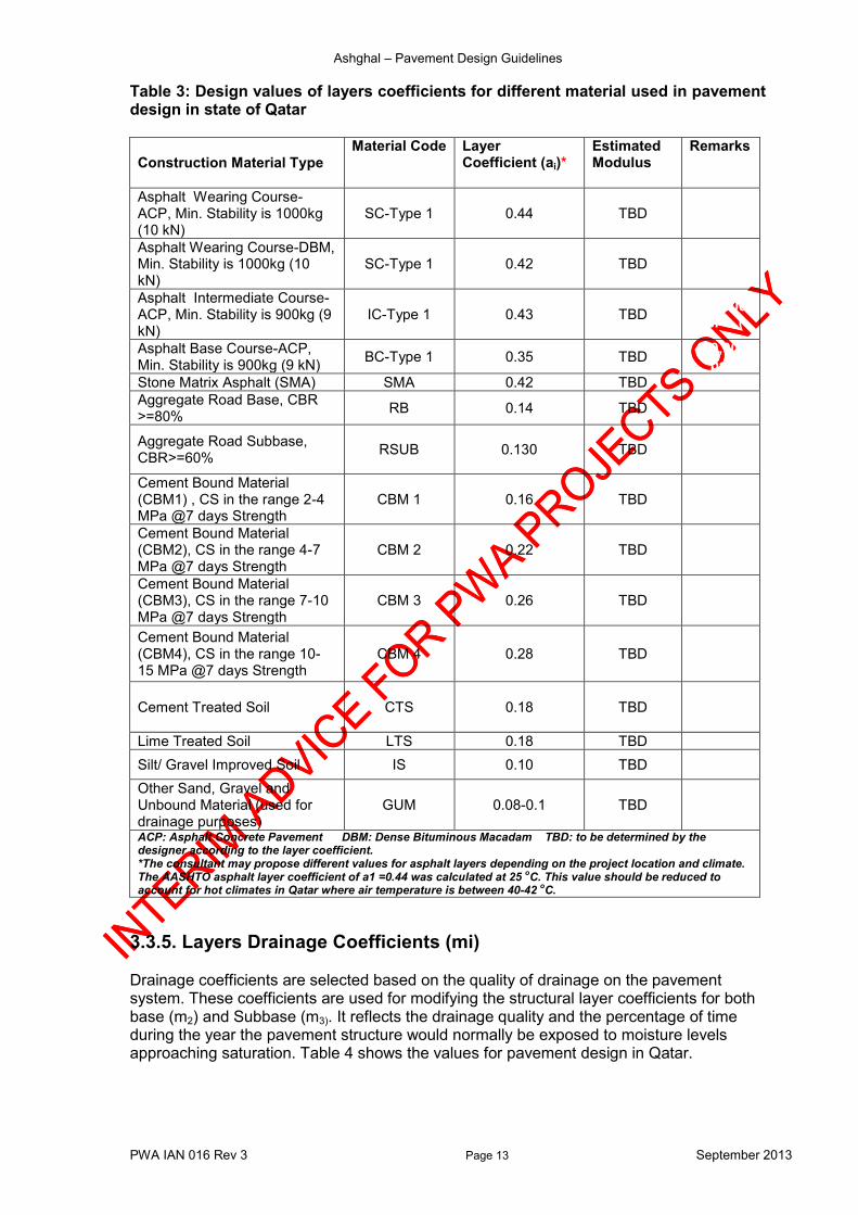
3.3.4. Layers coefficients (ai) Table 3 includes the design values of layers coefficients for material used in pavement design. These values are applicable for both new pavement and overlay designs.
Ashghal – Pavement Design Guidelines
PWA IAN 016 Rev 3 Page 13 September 2013
Table 3: Design values of layers coefficients for different material used in pavement design in state of Qatar
Construction Material Type Material Code Layer
Coefficient (ai)* Estimated Modulus
Remarks
Asphalt Wearing Course-ACP, Min. Stability is 1000kg (10 kN)
SC-Type 1 0.44 TBD ()
Asphalt Wearing Course-DBM, Min. Stability is 1000kg (10 kN)
SC-Type 1 0.42 TBD 400,000
psi (2750
Asphalt Intermediate Course- ACP, Min. Stability is 900kg (9 kN)
IC-Type 1 0.43 TBD 410,000 psi (
Asphalt Base Course-ACP, Min. Stability is 900kg (9 kN)
BC-Type 1 0.35 TBD 410,000
psi
Stone Matrix Asphalt (SMA) SMA 0.42 TBD 400,000
Aggregate Road Base, CBR >=80%
RB 0.14 TBD 36
Aggregate Road Subbase, CBR>=60%
RSUB 0.130 TBD 2800si (20Pa)
Cement Bound Material (CBM1) , CS in the range 2-4 MPa @7 days Strength
CBM 1 0.16 TBD
Cement Bound Material (CBM2), CS in the range 4-7 MPa @7 days Strength
CBM 2 0.22 TBD
Cement Bound Material (CBM3), CS in the range 7-10 MPa @7 days Strength
CBM 3 0.26 TBD
Cement Bound Material (CBM4), CS in the range 10-15 MPa @7 days Strength
CBM 4 0.28 TBD
Cement Treated Soil CTS 0.18 TBD 100,000
psi MPa)
Lime Treated Soil LTS 0.18 TBD 100,00)
Silt/ Gravel Improved Soil IS 0.10 TBD 1450000
Other Sand, Gravel and Unbound Material (used for drainage purposes)
GUM 0.08-0.1 TBD
ACP: Asphalt Concrete Pavement DBM: Dense Bituminous Macadam TBD: to be determined by the designer according to the layer coefficient. *The consultant may propose different values for asphalt layers depending on the project location and climate. The AASHTO asphalt layer coefficient of a1 =0.44 was calculated at 25
oC. This value should be reduced to
account for hot climates in Qatar where air temperature is between 40-42 oC.
3.3.5. Layers Drainage Coefficients (mi) Drainage coefficients are selected based on the quality of drainage on the pavement system. These coefficients are used for modifying the structural layer coefficients for both base (m2) and Subbase (m3). It reflects the drainage quality and the percentage of time during the year the pavement structure would normally be exposed to moisture levels approaching saturation. Table 4 shows the values for pavement design in Qatar.
Ashghal – Pavement Design Guidelines
PWA IAN 016 Rev 3 Page 14 September 2013
Table 4: Drainage coefficients for pavement layers in state of Qatar Layer Quality of
Drainage Drainage Coefficient (mi)
Time of exposure %
Granular Base Layer Fair 1.05 1-5
Granular Subbase Layer Fair 1.05 1-5
Improved Subgrade/capping layer- replaces the subbase
Fair 1.00 <1
For conditions in which the percentage of time during the year the pavement structure is exposed to moisture levels approaching saturation is well known or measured, the drainage coefficients shall be determined from Table 2.4 in the 1993 AASHTO Guide for the Design of Pavement Structures.
3.4. Pavement Design Inputs for Mechanistic approach
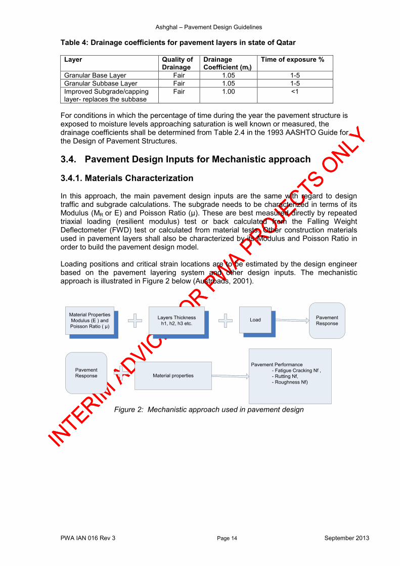
3.4.1. Materials Characterization In this approach, the main pavement design inputs are the same with regard to design traffic and subgrade calculations. The subgrade needs to be characterized in terms of its Modulus (MR or E) and Poisson Ratio (µ). These are best measured directly by repeated triaxial loading (resilient modulus) test or back calculated from the Falling Weight Deflectometer (FWD) test or calculated from material tests. Other construction materials used in pavement layers shall also be characterized by its Modulus and Poisson Ratio in order to build the pavement design model. Loading positions and critical strain locations are to be estimated by the design engineer based on the pavement layering system and other design inputs. The mechanistic approach is illustrated in Figure 2 below (Austroads, 2001).
Material Properties
Modulus (E ) and
Poisson Ratio ( μ)
Pavement Performance
- Fatigue Cracking Nf ,
- Rutting Nf,
- Roughness Nf)
Material properties
Layers Thickness
h1, h2, h3 etc.
Pavement
Response
Pavement
Response
Load
Figure 2: Mechanistic approach used in pavement design
Ashghal – Pavement Design Guidelines
PWA IAN 016 Rev 3 Page 15 September 2013
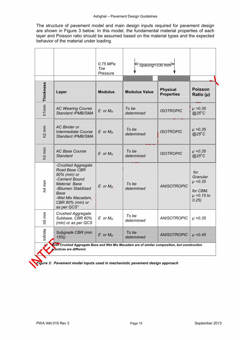
The structure of pavement model and main design inputs required for pavement design are shown in Figure 3 below: In this model, the fundamental material properties of each layer and Poisson ratio should be assumed based on the material types and the expected behavior of the material under loading.
0.75 MPa Tire Pressure
Spacing=330 mm
Th
ickn
es
s
Layer Modulus Modulus Value Physical Properties
Poisson Ratio (µ)
h1m
m
AC Wearing Course Standard /PMB/SMA
E or MR To be determined
ISOTROPIC µ =0.35 @25
oC
h2 m
m
AC Binder or Intermediate Course Standard /PMB/SMA
E or MR To be determined
ISOTROPIC µ =0.35 @25
oC
h3 m
m
AC Base Course Standard
E or MR To be determined
ISOTROPIC µ =0.35 @25
oC
h4 m
m
-Crushed Aggregate Road Base CBR 80% (min) or -Cement Bound Material Base -Bitumen Stabilized Base -Wet Mix Macadam, CBR 80% (min) or as per QCS*
E or MR To be determined
ANISOTROPIC
for Granular µ =0.35 for CBM, µ =0.15 to 0.25)
h5 m
m
Crushed Aggregate Subbase, CBR 60% (min) or as per QCS
E or MR To be determined
ANISOTROPIC µ =0.35
Infinite
Subgrade CBR (min 15%)
E or MR To be determined
ANISOTROPIC µ =0.45
Both Crushed Aggregate Base and Wet Mix Macadam are of similar composition, but construction
practices are different.
Figure 3: Pavement model inputs used in mechanistic pavement design approach

Ashghal – Pavement Design Guidelines
PWA IAN 016 Rev 3 Page 16 September 2013
Table 5 includes the range of the design values for the layer modulus to be used in mechanistic pavement design procedure:
Table 5: Design values for pavement layers used in mechanistic approach in state of Qatar
Input Indicative Typical
Range Modulus MPa
Design Value Modulus MPa *
Remarks
Asphalt/ Polymer Modified Bitumen (PMB) Modulus (MPa)
1000-5500 To be determined
Polymer Modified Bitumen (PMB) Asphalt Surface (Wearing ) Course -SC
Min 1900 MPa @45
oC
To be determined
Polymer Modified Bitumen (PMB) Asphalt Intermediate/Binder Course -IC
Min 1900 MPa @45
oC
To be determined
Polymer Modified Bitumen (PMB) Asphalt Base Course -BC
Min 1900 MPa @45
oC
To be determined
Asphalt Base Course /(Pen 60/70)
1000- 2500 @25
oC
To be determined
Cement Stabilized Base Modulus (MPa)
200-7,000 To be determined Depends on percentage of cement content
Bitumen Stabilized Base Modulus (MPa)
1000-2000 To be determined Typically with 1-1.5% cement and 2.5% foam bitumen
Crushed Aggregate Road Base for material with CBR>=80%
200-500 To be determined
Crushed Aggregate Subbase for material with CBR>=60%
200-400 To be determined
Subgrade CBR/Modulus As reported As reported
*This value shall be determined based on project location and climate. Modulus value should be adjusted to reflect the prevailing temperature in Qatar especially for the AC Wearing and Binder /Intermediate courses. Designer may propose different figures if found suitable for the project.
The following guidelines apply to the pavement design using mechanistic approach:
1. All granular pavement layers shall be sub-layered during pavement design and analysis unless it is clearly indicated that the granular layer is specified as a working platform.
2. Cement stabilized materials are very sensitive to the construction tolerances with regard to the minimum layer thickness that should be stabilized. This should be considered in the thickness design as well as in the construction specifications.
3. Granular maximum and minimum layers thickness shall be according to the
QCS-2010 or the latest version of the specifications.
4. The typical layer thickness for the cement stabilized layer ranges from 170 to 250mm.
Ashghal – Pavement Design Guidelines
PWA IAN 016 Rev 3 Page 17 September 2013
5. For the calculation of the cumulative damage to the pavement layers resulting from design traffic loading, the following constants are proposed. a. Asphalt Layers 1.1 b. Cement Stabilized Layer 8-10 c. Subgrade 1.6
3.5. General Guidelines for Expressway It is important to select proper asphalt mixtures for each layer of the pavement to meet its specific functions. The following general guidelines apply to the pavement design process using both Empirical (AASHTO 1993) and Mechanistic design methods. - The asphalt surface (wearing) course layer shall be designed to provide smooth,
high friction, and quite pavement. Asphalt Concrete (ACP) or Stone Matrix Asphalt (SMA) with high quality binder of performance grade PG76-10 S, H, V or E grades (e.g. Polymer-Modified Bitumen) shall be used for the Asphalt Surface (Wearing) layer.
- A High durability and rutting resistance asphalt Intermediate/binder course with high quality binder of performance grade PG76-10 S, H, V or E grades (e.g. Polymer-Modified Bitumen) shall be used for the Asphalt Intermediate/binder layer.
- Fatigue resistance of the lower base layer can be achieved by using fine aggregate
mix with rich-binder content of performance grade PG58-16 S, H, V or E grades (e.g. 60/70 penetration) shall be used for the Asphalt Base layer.
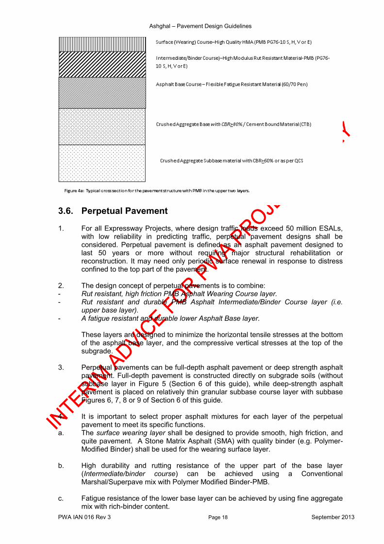
Based on Ashghal directive issued in 2012, Polymer Modified Bitumen (PMB) (that is asphalt performance grade PG76-10 S, H, V & E, as per IAN 019) shall be used in the top two (2) layers of pavement. The top two layers shall consist of a minimum of 50mm PMB wearing course plus a minimum of 70mm PMB intermediate course for a total PMB minimum thickness of 120mm. The remaining portion of the asphalt shall be conventional asphalt mix with PG58-16 S, H, V or E grades (i.e. 60/70 Penetration). The PMB shall be PG76-10 S, H, V or E grade depending on traffic type and level in accordance with guidelines outlined in Table 5.12 of IAN 019 (or latest revision). Figure 4a below represents a typical cross section for the pavement structure with PMB in the upper surface layer.
Ashghal – Pavement Design Guidelines
PWA IAN 016 Rev 3 Page 18 September 2013
3.6. Perpetual Pavement 1. For all Expressway Projects, where design traffic loads exceed 50 million ESALs,
with low reliability in predicting traffic, perpetual pavement designs shall be considered. Perpetual pavement is defined as an asphalt pavement designed to last 50 years or more without requiring major structural rehabilitation or reconstruction. It may need only periodic surface renewal in response to distress confined to the top part of the pavement.
2. The design concept of perpetual pavements is to combine: - Rut resistant, high friction PMB Asphalt Wearing Course layer. - Rut resistant and durable PMB Asphalt Intermediate/Binder Course layer (i.e.
upper base layer). - A fatigue resistant and durable lower Asphalt Base layer.
These layers are designed to minimize the horizontal tensile stresses at the bottom of the asphalt base layer, and the compressive vertical stresses at the top of the subgrade.
3. Perpetual pavements can be full-depth asphalt pavement or deep strength asphalt
pavement. Full-depth pavement is constructed directly on subgrade soils (without subbase layer in Figure 5 (Section 6 of this guide), while deep-strength asphalt pavement is placed on relatively thin granular subbase course layer with subbase Figures 6, 7, 8 or 9 of Section 6 of this guide.
4. It is important to select proper asphalt mixtures for each layer of the perpetual
pavement to meet its specific functions. a. The surface wearing layer shall be designed to provide smooth, high friction, and
quite pavement. A Stone Matrix Asphalt (SMA) with quality binder (e.g. Polymer-Modified Binder) shall be used for the wearing surface layer.
b. High durability and rutting resistance of the upper part of the base layer
(Intermediate/binder course) can be achieved using a Conventional Marshal/Superpave mix with Polymer Modified Binder-PMB.
c. Fatigue resistance of the lower base layer can be achieved by using fine aggregate
mix with rich-binder content.

Ashghal – Pavement Design Guidelines
PWA IAN 016 Rev 3 Page 19 September 2013
5. Performance tests should be used to characterize the resistance of the asphalt
layers to permanent deformation and fatigue cracking. 6. Good bonding between pavement layers is essential to ensure the long-term
performance of the pavement structure. In summary, perpetual pavement options can be used in the following cases:
Direct instruction from the client to adopt one of the typical perpetual pavement structures of design life of 50 years or more regardless of traffic level and subgrade condition.
Lack of information on future changes in traffic loads.
Design traffic volumes and axle loading cannot be estimated accurately as a result of uncertain development or planning policy.
Design Traffic loading exceeds 50 million ESAL over the design period. Various pavement structures options or types are shown in Section 6 of this guide. The preferred option can be adopted depending on the subgrade Strength and traffic levels and other design consideration including cost and constructability. The required thickness of each layer shall be determined by the design consultant. Figure 4b below shows the general structure of a perpetual pavement section.
3.7. Design Variables Regardless of the type of road pavement proposed and the adopted method of design, the design of the pavement usually involves consideration of the following main three input variables: TRAFFIC
1. Design life 2. Design Traffic and Road Hierarchy
See Appendix A

Ashghal – Pavement Design Guidelines
PWA IAN 016 Rev 3 Page 20 September 2013
GEOTECHNICAL
1. Subgrade strength evaluation 2. Environmental parameters, i.e. rainfall, daily and annual temperature variations 3. Ground Water levels
See Appendix B
MATERIALS
1. Pavement Structure 2. Pavement Materials 3. Construction and Maintenance Considerations – Value Engineering
See Appendix C
3.8. Design approaches and acceptance 1. The following guidelines aim at defining the basic requirements in respect to
pavement structure including asphalt layers or surface characteristics. 2. The designer may use and consider more than one alternative or approach, other
than the recommended method outlined in this document, to calculate the design traffic loading or allowable number of repetitions and the service life offered by the proposed design. The Consultant shall include in his submission a brief description of the alternative approaches used in the calculations.
Flexible pavements containing one or more bound (asphaltic concrete) layers or that including cement stabilised layers shall be designed in accordance with AASHTO Pavement Design method.
As an alternative to AASHTO Pavement Design, the designer may use/verify his design using other mechanistic or mechanistic–empirical design methods taking into consideration the local design inputs.
3. The pavement design will only be accepted if the maximum allowable traffic
volumes exceed the design traffic loading.
3.9. Pavement Design Life Table 6 provides guidance on design life based on the road system classification in Qatar. Table 6: Design life based on the road system classification in Qatar
Road Class* Design Life (Years)
First Overlay (Years)-Expected
Remarks
Primary Routes (Freeways and Expressway**)
20 12
Secondary Routes (Arterials)
20 12
Tertiary Routes (Collectors)
20 10
Local Routes (Local) 20 10 *Ref: QHDM-97 **Terms in brackets represent the new highway classes which are still under approval process.
Ashghal – Pavement Design Guidelines
PWA IAN 016 Rev 3 Page 21 September 2013
During this design period/design life, the pavement of the road is expected to carry the traffic in satisfying structural and functional conditions with no major failure on any part of the road.
3.10. Special Provisions
3.10.1. Pavement Constructed in High Ground Water Areas Local experience in designing and constructing pavements on fully or partially saturated subgrade in Qatar has indicated the need to lift the road level and to keep a constant buffer zone between the ground water surface and the bottom of the sub base layer. International practices recommend that the depth for this buffer zone shall be at least 1.2 m (in USA standards, this depth may reach up to 1.7m). In urban areas, it may not always be feasible have a buffer zone of 1.2 m in areas of high ground water; in this case, a positive ground water control system may be required. In road projects where ground water level varies along the road alignment, there should be proactive measures taken to prevent saturation the fines in the pavement layers in high ground water areas. The subbase/subgrade should be drained to a ditch at the hard shoulder. The depth of the cut-off/collector should be 1m below the sub base layer. Where considered necessary a Geotextile fabric material should be used to prevent the migration of fine material from the subbase layer that can occur when a rise in the ground water level takes place. This protection should be provided wherever required. The Geotextile filter fabric shall be as per the QCS 2010 or the latest version. In general, the Geotextile should be formed into a network such that the filaments or yarns retain dimensional stability relative to each other including selvedge. Alternatively a Cement Bound Material or Chemically Stabilised Material may be proposed. The designer shall identify where the longitudinal profile of the Expressway enters the ground water influence zone (underpasses) and determine an appropriate structural solution, or combination of structural/drainage solution to mitigate any deterioration to the pavement during the design life of the road/structure (120 years). The design of Asphalt layers on top of any such structures shall also be identified.
3.11. Value Engineering For the purpose of optimizing the pavement design, the designer should implement Value Engineering process for each project. The term Value Engineering (VE) is a systematic process of review and analysis of a project, during the concept and design phases, by a multidiscipline team of persons not involved in the project together with the Design Manager, to confirm and assess alternative design. Taking into consideration that each of the proposed design alternatives has to sustain the
design traffic volume for the intended design life, the VE exercise has to consider other factors in order to select the optimum design option.
The main objective of this VE review is to provide recommendations for:
1. Providing a safe, reliable and efficient design at the lowest overall cost. 2. Improving performance. 3. Improving the value and quality and/or life-cycle cost of the project; and 4. Reducing the time to complete the project.
Ashghal – Pavement Design Guidelines
PWA IAN 016 Rev 3 Page 22 September 2013
Issues related to Construction cost, maintenance cost, sustainability, constructability, re-use of raw or processed material, safety, environment and others shall be considered when implementing VE to the pavement design. A constructability or buildability review is a process for project management to review construction methods from start to finish, before the construction phase. It aims at identifying obstacles before a project is actually built to reduce or prevent error, delays, and cost overrun. The sustainability of the design creates lasting benefits through an integrated consideration of social, environmental and economic aspects in the proposed designs. Other terms are self-explanatory. It is a primary tenet of Value Engineering that quality not to be reduced as a consequence of pursuing value improvements. Therefore, the main target in a VE exercise is to propose alternatives that satisfy the technical requirements at reduced cost or enhance and increase the ease of construction whilst maintaining quality. VE analysis should also concentrate on value issues, risk issues and prioritization of factors influencing value.

Ashghal – Pavement Design Guidelines
PWA IAN 016 Rev 3 Page 23 September 2013
4. Pavement Design Submittal Regardless of the size of the road project, the Pavement Design Report (PDR) must include, but not limited to, the following elements:
1. Project General Layout Plan and description of purpose and pavement design life. 2. Design traffic information (raw). 3. Geotechnical Investigation Report 4. Full analysis of the geotechnical and traffic data 5. Main design inputs to be used in pavement design 6. A brief description of the basic and alternative approaches used in the calculations. 7. Detailed pavement design calculations, cross sections, all relevant drawings,
modifications, specifications requirements. 8. Value Engineering-consideration of the options/Constructability Review 9. Recommended pavement design–after design optimization. 10. Appendices
5. Reference documents Material used in the design of pavement structures shall be according to the following main references:
1. AASHTO (1993). AASHTO Guide for Design of Pavement Structures. American Association of State Highway and Transportation Officials, AASHTO, Washington D.C., USA.
2. Austroads (2001). Pavement Design: A Guide to the Structural Design of Road Pavements. Austroads, Sydney, Australia.
3. Qatar Construction Specifications-QCS 2007, QCS 2010 or the latest version. 4. Amendments to QCS 2010 and particular specifications proposals. 5. Qatar Highway Design Manual-QHDM adjusted to reflect QCS2007 requirements. 6. "Upgrading the Methods Used in the Construction of Asphalt Pavements in the
State of Qatar", CMS Engineering Group. LLC. 7.
6. Figures
The following combinations (Types) can also be used in perpetual pavement. The thickness shall be determined by the consultant based on project location, road class, traffic level and subgrade strength.
Ashghal – Pavement Design Guidelines
PWA IAN 016 Rev 3 Page 24 September 2013
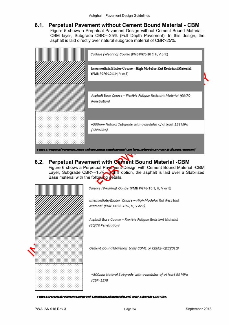
6.1. Perpetual Pavement without Cement Bound Material - CBM Figure 5 shows a Perpetual Pavement Design without Cement Bound Material - CBM layer, Subgrade CBR>=25% (Full Depth Pavement). In this design, the asphalt is laid directly over natural subgrade material of CBR>25%.
6.2. Perpetual Pavement with Cement Bound Material -CBM Figure 6 shows a Perpetual Pavement Design with Cement Bound Material -CBM Layer, Subgrade CBR>=15%. In this option, the asphalt is laid over a Stabilized Base material with the following details.

Ashghal – Pavement Design Guidelines
PWA IAN 016 Rev 3 Page 25 September 2013
6.3. Perpetual Pavement with Cement Bound Material - CBM and Crushed Aggregate Subbase
Figure 7 shows a Perpetual Pavement Design with Cement Bound Material - CBM Layer, Crushed Aggregate Subbase layer and Subgrade CBR>=15%. In this option, the asphalt is laid over a Stabilized Base material with the following details.
6.4. Perpetual Pavement with Bitumen Bound Material – BBM Figure 8 shows a Perpetual Pavement Design with Bitumen Bound Material - BBM Layer, Subgrade CBR>=15%.
Ashghal – Pavement Design Guidelines
PWA IAN 016 Rev 3 Page 26 September 2013
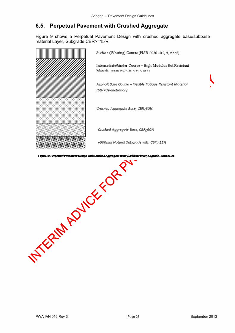
6.5. Perpetual Pavement with Crushed Aggregate Figure 9 shows a Perpetual Pavement Design with crushed aggregate base/subbase material Layer, Subgrade CBR>=15%.
Ashghal – Pavement Design Guidelines
PWA IAN 016 Rev 3 Page 27 September 2013
Appendix A – Traffic Traffic is considered one of the most important factors in pavement design. It controls both pavement layers thickness and material type used to construct the pavement. In pavement design, only heavy vehicles are considered due to their disproportionate effect on pavement structural and functional performance. Passenger Car Unit (PCU) has almost negligible effect on pavement structure. In addition to the long term traffic prediction, the designer MUST consider the construction traffic that is likely to use the carriageway in the lead up to 2022, specifically for the project in hand and where trucks are prohibited except for access etc.
A.1 Design Traffic Calculations For the purpose of pavement design, traffic can be calculated using one of the following three methods: a) Classified Counts (Axles configuration and number): This approach is considered
the most accurate method for estimation design traffic loading over the design period. In this approach, the number and configuration of axles for each vehicle class are counted and used in design traffic calculations. The classes include passenger cars, buses, light trucks and commercial vehicles or heavy trucks. The equivalent design loads can then be estimated using axle load equivalency factors to convert all axles into standard 8.2 tonne Single Axle Dual Tyres used in pavement design. The yearly equivalent axle load is then projected and factored over the design period in order to calculate the cumulative design traffic loading.
b) Classified Counts (Truck class): In this method, a truck factor is assigned to each truck class. The equivalent design loads can then be estimated using truck equivalency factors to convert all traffic into standard 8.2 tonne Single Axle Dual Tyres used in pavement design. The yearly equivalent axle load is then projected and factored over the design period in order to calculate the cumulative design traffic loading.
c) Truck percentage: This method is used whenever classified counts are not
possible. In this case, the percentage of heavy traffic is estimated and used to calculate the design traffic loading in terms of ESAL's over the selected design period using a single truck factor calculated based on field surveys and research studies. The yearly equivalent axle load is then projected and factored over the design period in order to calculate the cumulative design traffic loading.
Regardless of method used to estimate traffic volumes and design traffic loads, a comparison with the traffic volume generated by Qatar Transportation Master Plan (TMPQ) traffic model should be conducted in arriving at the appropriate proposed loading. In Qatar, being a developing economy, the uncertainty in predicting traffic volume and type is relatively high. To predict traffic growth, the following three traffic categories shall be considered by the design engineer, which can be site/project dependent. 1. Normal traffic, which uses the route or is expected to use the route if it is new
one.
2. Diverted traffic, which is attracted to the route because of the improved pavement.
3. Developed traffic, which arises from either planned or unplanned development
along the road corridor (this type is sometimes termed generated traffic).
Ashghal – Pavement Design Guidelines
PWA IAN 016 Rev 3 Page 28 September 2013
Normal traffic can be assumed to continue to grow according to current trends, either as a fixed number of vehicles per year or as a cumulative percentage of current total - dependent on traffic model. Diverted traffic can be considered from an economic perspective. This should include all vehicles that would save either time or money by switching from an existing route to the newly constructed route. Diverted traffic is usually predicted to grow at the same rate as the traffic on the road from which it has been diverted. The quantity of the traffic due to planned development can be estimated from the details of policy plans and traffic model. The developed (generated) traffic, on the other hand, is far more difficult to predict. It is, however, influenced by the availability of land for such development, economic growth, and historical data from previous road projects. Construction traffic due to new development shall also be considered. Traffic prediction shall also consider traffic type, heavy traffic limitation use of driving lane, traffic directional distribution, various axle loads and their corresponding growth rates. Based on the available traffic data, the design cumulative equivalent axle repetitions over the design period can be estimated using an appropriate method taking into consideration the growth rate of traffic as shown in the following sections.
A.2 Direction Distribution Considerations 1. Based on the classified traffic counts or the forecasted traffic flows from TMPQ
traffic model, traffic direction distribution shall be determined. 2. Directional distribution in Qatar is D% = 0.55 3. Where the reported ESALs/day/direction is based upon a 50:50 split between
directions, traffic in either direction can be used for design purposes. 4. In cases where directional distribution factors are used and the pavement structure
is designed on the basis of distributed traffic, consideration should be given to the design of variable cross-sections if found practical.
5. There may be special cases where this does not hold true (such as more loaded trucks in one direction and more empty trucks in the other). In these special cases, it may be necessary to confirm actual distribution through a count or a WIM survey. The statistics reported are for total ESALs/day/direction.
A.3 Lane Distribution Considerations The following are typical values that shall be considered under normal traffic conditions. These numbers shall be used with caution if directional distribution is not balanced and/or a designated heavy vehicle lane(s) are used: 1. On multilane highways, the total traffic volume would represent all lanes in one
direction. 2. However, the ASSHTO design guidelines can be used in case such distribution
factors are not available based on actual field surveys. AASHTO pavement design manual provides good basis for traffic distribution and % of design traffic in the design lane depending on the number of lanes open to truck traffic in each direction. In Qatar, the following values can be used (Table A-1 below).

Ashghal – Pavement Design Guidelines
PWA IAN 016 Rev 3 Page 29 September 2013
Table A-1: Traffic distribution and % of design traffic in the design lane proposed for Qatar
Number of Lanes* % in Design Lane Value for Pavement Design
1 100 100
2 80-100 0.90
3 60-80 0.60
4 40-60 0.40
5 To be determined NA
6 To be determined NA * Number of lanes is defined as the numbers of lanes open to HGV traffic, for example, on Salwa Rd, the number of lanes open to HGV traffic is 2.
A.4 Traffic Growth Historical growth factors in Qatar that have been used to estimate design ESALs for a road project are as shown in Table A-2 below: Table A-2: Proposed growth factors for traffic to be used to estimate design ESALs for State of Qatar
Type Traffic growth rate per annum compounded* Remarks
New construction projects 4-6%
Rehabilitation and widening/dualling Projects 2-4% *Recommended however, Consultant may propose different figures to the Engineer for approval
For road projects located in areas subjected to heavy development, the design engineer shall determine traffic growth factor based on solid and reliable assumptions. Traffic growth can be calculated as follows: Case 1: If the future Average Daily Traffic (ADT) and initial ADT are provided, then traffic
growth rate can be calculated using the following equation:
R = [((ADTf / ADTi) (1/(f-i)) ) -1] x 100
Where:
R = Growth Rate (%) ADTf = Average daily traffic in the future year ADTi = Average daily traffic in the initial year i= Initial year for ADT f = Future year for ADT
Case 2: If an ADT and growth rate is provided, then a future ADT can be calculated using the following equation:
ADTf = ADTi (1+R) (f-I)
Where:
R = Growth Rate (%) ADTf = Average daily traffic for future year ADTi = Average daily traffic for initial year (year traffic data is provided) i = Initial year for ADT f = Future year for ADT
Ashghal – Pavement Design Guidelines
PWA IAN 016 Rev 3 Page 30 September 2013
A.5 Cumulative Growth Factor The cumulative growth factor calculated over a design life is given by the following formula:
G=((1+R)n -1))/R
Where: G= Cumulative Growth Factor R= Growth Rate (%) n= Number of years
A.6 Equivalent Single Axle Load Factors
a) When vehicle classified counts or Weigh In Motion (WIM) data are available, the actual Equivalent Single Axle load factors (ESALF) shall be determined.
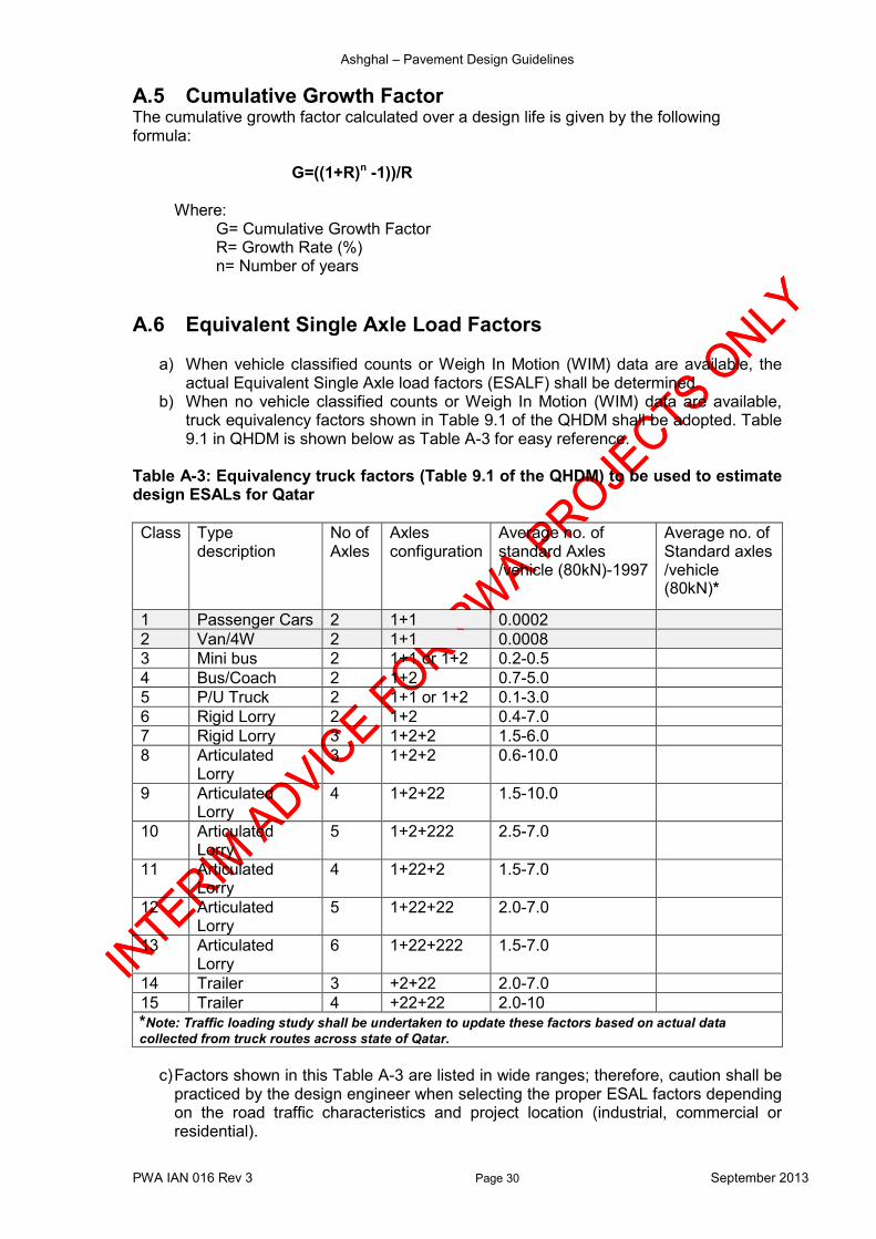
b) When no vehicle classified counts or Weigh In Motion (WIM) data are available, truck equivalency factors shown in Table 9.1 of the QHDM shall be adopted. Table 9.1 in QHDM is shown below as Table A-3 for easy reference.
Table A-3: Equivalency truck factors (Table 9.1 of the QHDM) to be used to estimate design ESALs for Qatar
Class Type description
No of Axles
Axles configuration
Average no. of standard Axles /vehicle (80kN)-1997
Average no. of Standard axles /vehicle (80kN)*
1 Passenger Cars 2 1+1 0.0002
2 Van/4W 2 1+1 0.0008
3 Mini bus 2 1+1 or 1+2 0.2-0.5
4 Bus/Coach 2 1+2 0.7-5.0
5 P/U Truck 2 1+1 or 1+2 0.1-3.0
6 Rigid Lorry 2 1+2 0.4-7.0
7 Rigid Lorry 3 1+2+2 1.5-6.0
8 Articulated Lorry
3 1+2+2 0.6-10.0
9 Articulated Lorry
4 1+2+22 1.5-10.0
10 Articulated Lorry
5 1+2+222 2.5-7.0
11 Articulated Lorry
4 1+22+2 1.5-7.0
12 Articulated Lorry
5 1+22+22 2.0-7.0
13 Articulated Lorry
6 1+22+222 1.5-7.0
14 Trailer 3 +2+22 2.0-7.0
15 Trailer 4 +22+22 2.0-10
*Note: Traffic loading study shall be undertaken to update these factors based on actual data
collected from truck routes across state of Qatar.
c) Factors shown in this Table A-3 are listed in wide ranges; therefore, caution shall be practiced by the design engineer when selecting the proper ESAL factors depending on the road traffic characteristics and project location (industrial, commercial or residential).

Ashghal – Pavement Design Guidelines
PWA IAN 016 Rev 3 Page 31 September 2013
A.7 Determination of the ESALs per day per direction The daily number of Equivalent Single Axle Loads is derived by multiplying the percentage of each HGV class by the mean average daily number of standard axles per HGV or the relevant truck factor. The determination of the ESALs per day per direction is related to the Average Annual Daily Traffic (AADT). The AADT is the average daily one/two way traffic expressed as vehicles per day for the period in which the data collected (i.e. 1, 7, 30, 360 days). Peak Hour Volume (PHV) obtained by counting or estimated from the traffic model TMPQ, can also be used to determine the Average Daily Traffic (ADT) if the Peak Hour Factors (PHF) is well established for both rural and urban areas. The following Table A-4 shows the recommend PHF used to determine the ADT volumes. The ADT should be converted to Average Annual Daily Traffic (AADT) based on the appropriate factor which depends on the number of count days. Table A-4: PHF used to determine the ADT volumes in State of Qatar
Counts period PHF to convert traffic into ADT* Rural Urban
1 hours 0.10 0.14
12 hours 0.70 0.75
16 hours 0.85 0.88
24 hours 1.00 1.00
Note that ADT=PHV/PHF *the above figures are just indicative. The consultants may propose different percentages or use the available traffic models if found reliable.
A.8 Cumulative design standard axles
The cumulative millions single axle load value is derived by multiplying the ESAL by design period i.e. 20 years, taking into consideration all the above design and growth factors.
For intersections, design traffic at an intersection should be calculated by adding the design traffic applicable to one road to the design traffic applicable to the cross road.
A.9 Traffic inputs guidelines, assumptions and calculations The following assumptions and guidelines shall be considered in the calculation process for the design traffic loading:
Traffic-related data collected on any road project can be used for both new construction and for determining the rehabilitation design for the existing pavements. Such data may include traffic volumes, (PHV and ADT), axle load, axle configurations and number of standard load applications.
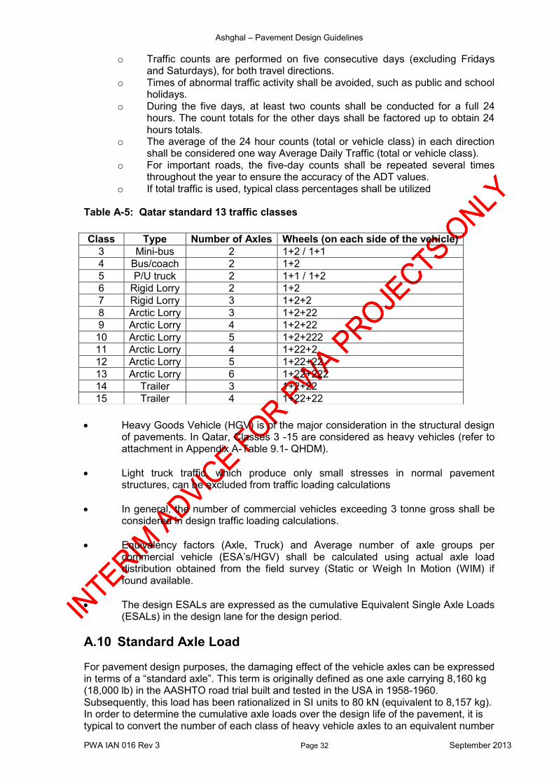
Classified counts shall be carried out using the Qatar standard 13 traffic classes presented in Table A-5 below (Classes 1 and 2, consists of cars, 4-wheel drive vehicles, and light pick-ups, respectively, that cause negligible pavement damage, and hence, have been omitted.)
The classification can be manual or automated. However, in order to ensure that appropriate axle loading and composition percentages are representative of the yearly traffic, the following method shall be followed unless otherwise stated in the contract (in the case of detailed traffic data is unavailable).
Ashghal – Pavement Design Guidelines
PWA IAN 016 Rev 3 Page 32 September 2013
o Traffic counts are performed on five consecutive days (excluding Fridays and Saturdays), for both travel directions.
o Times of abnormal traffic activity shall be avoided, such as public and school holidays.
o During the five days, at least two counts shall be conducted for a full 24 hours. The count totals for the other days shall be factored up to obtain 24 hours totals.
o The average of the 24 hour counts (total or vehicle class) in each direction shall be considered one way Average Daily Traffic (total or vehicle class).
o For important roads, the five-day counts shall be repeated several times throughout the year to ensure the accuracy of the ADT values.
o If total traffic is used, typical class percentages shall be utilized Table A-5: Qatar standard 13 traffic classes
Heavy Goods Vehicle (HGV) is of the major consideration in the structural design of pavements. In Qatar, Classes 3 -15 are considered as heavy vehicles (refer to attachment in Appendix A-Table 9.1- QHDM).
Light truck traffic, which produce only small stresses in normal pavement structures, can be excluded from traffic loading calculations
In general, the number of commercial vehicles exceeding 3 tonne gross shall be considered in design traffic loading calculations.
Equivalency factors (Axle, Truck) and Average number of axle groups per commercial vehicle (ESA’s/HGV) shall be calculated using actual axle load distribution obtained from the field survey (Static or Weigh In Motion (WIM) if found available.
The design ESALs are expressed as the cumulative Equivalent Single Axle Loads (ESALs) in the design lane for the design period.
A.10 Standard Axle Load For pavement design purposes, the damaging effect of the vehicle axles can be expressed in terms of a “standard axle”. This term is originally defined as one axle carrying 8,160 kg (18,000 lb) in the AASHTO road trial built and tested in the USA in 1958-1960. Subsequently, this load has been rationalized in SI units to 80 kN (equivalent to 8,157 kg). In order to determine the cumulative axle loads over the design life of the pavement, it is typical to convert the number of each class of heavy vehicle axles to an equivalent number
Class Type Number of Axles Wheels (on each side of the vehicle)
3 Mini-bus 2 1+2 / 1+1
4 Bus/coach 2 1+2
5 P/U truck 2 1+1 / 1+2
6 Rigid Lorry 2 1+2
7 Rigid Lorry 3 1+2+2
8 Arctic Lorry 3 1+2+22
9 Arctic Lorry 4 1+2+22
10 Arctic Lorry 5 1+2+222
11 Arctic Lorry 4 1+22+2
12 Arctic Lorry 5 1+22+22
13 Arctic Lorry 6 1+22+222
14 Trailer 3 1+2+22
15 Trailer 4 1+22+22
Ashghal – Pavement Design Guidelines
PWA IAN 016 Rev 3 Page 33 September 2013
of 80 kN standard axles. Axle loads are related to the standard axle using the following relationship:
)
)
The exponent, a, in the above Equation typically varies between 4 to 5 depending on the type of distress being considered and the design of the pavement structure. This exponent is less for weaker asphalt pavements.
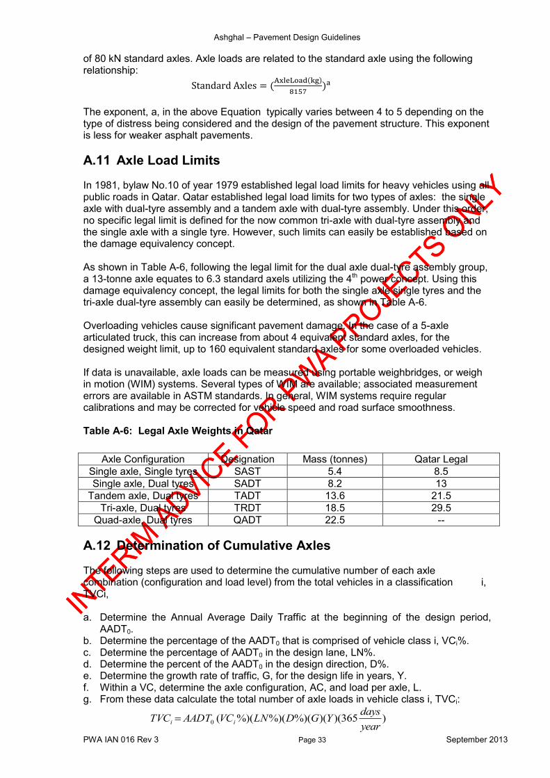
A.11 Axle Load Limits In 1981, bylaw No.10 of year 1979 established legal load limits for heavy vehicles using all public roads in Qatar. Qatar established legal load limits for two types of axles: the single axle with dual-tyre assembly and a tandem axle with dual-tyre assembly. Under this order, no specific legal limit is defined for the now common tri-axle with dual-tyre assembly and the single axle with a single tyre. However, such limits can easily be established based on the damage equivalency concept. As shown in Table A-6, following the legal limit for the dual axle dual-tyre assembly group, a 13-tonne axle equates to 6.3 standard axels utilizing the 4th power concept. Using this damage equivalency concept, the legal limits for both the single axle single tyres and the tri-axle dual-tyre assembly can easily be determined, as shown in Table A-6. Overloading vehicles cause significant pavement damage. In the case of a 5-axle articulated truck, this can increase from about 4 equivalent standard axles, for the designed weight limit, up to 160 equivalent standard axles for some overloaded vehicles. If data is unavailable, axle loads can be measured using portable weighbridges, or weigh in motion (WIM) systems. Several types of WIM are available; associated measurement errors are available in ASTM standards. In general, WIM systems require regular calibrations and may be corrected for vehicle speed and road surface smoothness. Table A-6: Legal Axle Weights in Qatar
A.12 Determination of Cumulative Axles The following steps are used to determine the cumulative number of each axle combination (configuration and load level) from the total vehicles in a classification i, TVCi, a. Determine the Annual Average Daily Traffic at the beginning of the design period,
AADT0. b. Determine the percentage of the AADT0 that is comprised of vehicle class i, VCi%. c. Determine the percentage of AADT0 in the design lane, LN%. d. Determine the percent of the AADT0 in the design direction, D%. e. Determine the growth rate of traffic, G, for the design life in years, Y. f. Within a VC, determine the axle configuration, AC, and load per axle, L. g. From these data calculate the total number of axle loads in vehicle class i, TVCi:
)365)()(%)(%)(%)((0year
daysYGDLNVCAADTTVC ii
Axle Configuration Designation Mass (tonnes) Qatar Legal
Single axle, Single tyres SAST 5.4 8.5
Single axle, Dual tyres SADT 8.2 13
Tandem axle, Dual tyres TADT 13.6 21.5
Tri-axle, Dual tyres TRDT 18.5 29.5
Quad-axle, Dual tyres QADT 22.5 --

Ashghal – Pavement Design Guidelines
PWA IAN 016 Rev 3 Page 34 September 2013
Appendix B – Geotechnical Considerations Pavement design procedure must include a consideration of the underlying subgrade soil conditions. The subgrade soil properties and the physical and chemical characteristics will determine the thickness of pavement structure that can resist the expected design traffic loading. Sampling, testing and reporting shall be as per the standards outlined in the QCS 2010 or the latest edition. The geotechnical investigation should include collection of detailed data and information on the following:
Subgrade layers
Material type
Material composition
Subgrade strength and physical properties
Water Table / Ground Water Level
Physical/chemical properties of groundwater Field tests that should be carried out include the following as minimum requirements:
Cone Penetration test
Soil Electrical Resistivity test
In situ Density test
In situ California Bearing Ratio test
Infiltration test - permeability
Falling Head test – permeability
Water Table / Ground Water Level The main objective of this investigation is to provide information on the existing soil and groundwater condition in order to derive recommendations on the most suitable foundation for the design of the pavement and other road structures. The laboratory tests carried out on samples extracted from the site must include the followings as minimum requirements:
Sieve Analysis & Atterberg limits
Unconfined Compressive Strength
Specific Gravity
Chemical tests, which include:
o Sulphate content, soil and water o Chloride content , soil and water o Determination of pH value, soil and water o Carbonate content, soil and water
Moisture Content-Dry Density relationship
California Bearing Ratio or determination of Resilient Modulus
Direct Shear Strength

Ashghal – Pavement Design Guidelines
PWA IAN 016 Rev 3 Page 35 September 2013
The pavement design report must include a brief description on the following elements:
Sub surface profile description with Long Section and Cross Sections showing Ground Water Levels
Material classification
Sieve Analysis results
Atterberg limits analysis
In Situ Density and Moisture Content
California Bearing Ratio (CBR)
Chemical analysis
Subgrade pH
B.1 Subgrade Design CBR Where the pavement design is undertaken using empirical design approach, the measure of subgrade strength shall be the soaked California Bearing Ratio (CBR). AASHTO 1993 method is considered a typical example of an empirical approach in pavement design. In order to design the pavement structure, the Design CBR for each subgrade area is computed as the average values of the soil strength:
Design CBR= Mean of all estimated CBR’s at appropriate locations
Where a mechanistic or mechanistic-empirical approaches using linear elastic theory is employed for pavement design, the measure of subgrade strength shall be in terms of the elastic parameters (modulus (MR or E), Poisson's ratio (µ).The Design CBR for each subgrade area is computed by using the appropriate formulae as follows:
Recommended Design CBR = 10th percentile of all estimated CBR’S, for five or more results.
The 10%ile value is defined as the subgrade strength value that 90% of all the test values are equal or greater than. This value can be calculated using the following formula:
10th percentile Design CBR=Mean CBR - 1.3*SD
Where: Mean CBR: the mean of all estimated/measured CBRs, and SD: the standard deviation of all values.
B.2 Subgrade Modulus (Resilient Modulus)
In order to design the pavement structure as per the AASHTO method, the mean CBR value of the subgrade should be used to calculate the Resilient Modulus MR. The resilient modulus is a measure of the elastic property of the soil recognizing certain nonlinear characteristics. The resilient modulus can be used directly for the design of flexible pavement but must be converted to a modulus of subgrade reaction (k- value) for the design of rigid or composite pavements.
Because not all road agencies have the equipment to perform resilient modulus testing, there are several approximate correlations that have been developed to correlate other soil indicators to resilient modulus. However, it must be emphasized that these relationships are approximate at best and should be applied carefully.
Caution must be practiced when selecting a design Resilient Modulus. An analysis of all the soils data should be conducted prior to selecting a value.
If the value of the Coefficient of Variance (CV) is greater than 10%, the average Resilient Modulus (MR) value should not be used as the design MR. If the CV is
Ashghal – Pavement Design Guidelines
PWA IAN 016 Rev 3 Page 36 September 2013
greater than 10%, and then the Pavement Designer should look at segmenting the road into distinct sections with similar modulus values and designing those sections based on average MR.
If no sections clearly exist, then use the 10%ile of the MR values to obtain the design MR.
For those locations with an actual MR less than the design MR, then the pavement designer should consider a separate design for that location or subgrade replacement in that area.
If Resilient Modulus results are not available, then designer can use any of the empirical equations developed for this purpose.
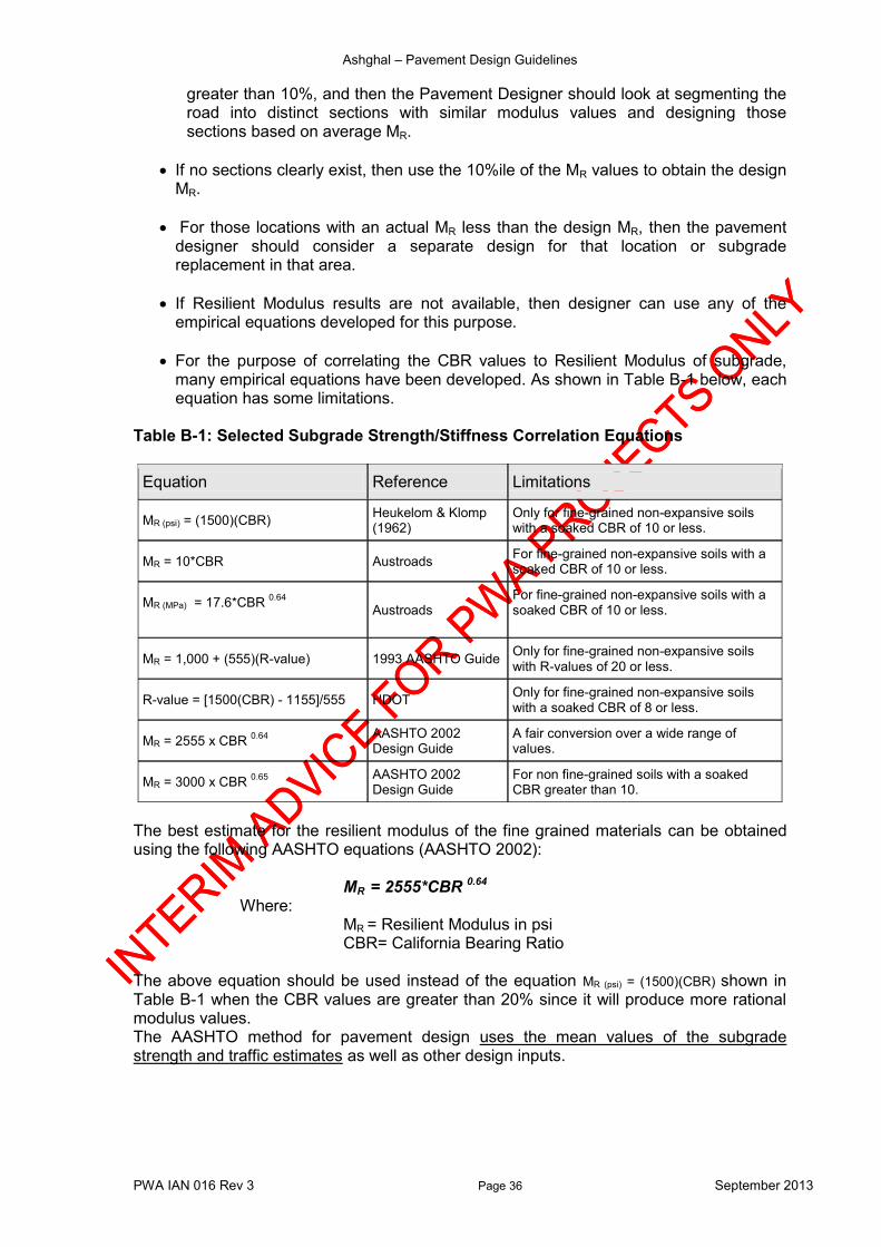
For the purpose of correlating the CBR values to Resilient Modulus of subgrade, many empirical equations have been developed. As shown in Table B-1 below, each equation has some limitations.
Table B-1: Selected Subgrade Strength/Stiffness Correlation Equations
Equation Reference Limitations
MR (psi) = (1500)(CBR) Heukelom & Klomp (1962)
Only for fine-grained non-expansive soils with a soaked CBR of 10 or less.
MR = 10*CBR Austroads For fine-grained non-expansive soils with a soaked CBR of 10 or less.
MR (MPa) = 17.6*CBR 0.64
Austroads
For fine-grained non-expansive soils with a soaked CBR of 10 or less.
MR = 1,000 + (555)(R-value) 1993 AASHTO Guide Only for fine-grained non-expansive soils with R-values of 20 or less.
R-value = [1500(CBR) - 1155]/555 HDOT Only for fine-grained non-expansive soils with a soaked CBR of 8 or less.
MR = 2555 x CBR 0.64
AASHTO 2002 Design Guide
A fair conversion over a wide range of values.
MR = 3000 x CBR 0.65
AASHTO 2002 Design Guide
For non fine-grained soils with a soaked CBR greater than 10.
The best estimate for the resilient modulus of the fine grained materials can be obtained using the following AASHTO equations (AASHTO 2002):
MR = 2555*CBR 0.64
Where: MR = Resilient Modulus in psi CBR= California Bearing Ratio
The above equation should be used instead of the equation MR (psi) = (1500)(CBR) shown in Table B-1 when the CBR values are greater than 20% since it will produce more rational modulus values. The AASHTO method for pavement design uses the mean values of the subgrade strength and traffic estimates as well as other design inputs.
Ashghal – Pavement Design Guidelines
PWA IAN 016 Rev 3 Page 37 September 2013
B.3 Modulus back calculated from Deflection a) When Falling Weight Deflectometer (FWD) testing is conducted and the back-
calculated resilient modulus is determined, then,
The Design MR = 0.33 Back-calculated MR
If CBR and back-calculated MR results are available, use the smaller Design MR for pavement design purposes.
For partially saturated soils, the stiffness is mainly dependent on the negative pore-water pressure or soil moisture suction. Therefore, the laboratory prepared specimen exhibits essentially the same stiffness as undisturbed specimens for comparable suction values. During Construction, the CBR shall be checked to confirm that it is in conformance with the design assumptions for that section of pavement. This case may present as a result of the effect of both construction traffic and weather. Final grading to subgrade level shall be carried out in conjunction with construction of subsequent layers so as to minimise the damage to the subgrade due to construction traffic and/or inclement weather. If subgrade has deteriorated then a capping layer should be considered to help protecting the subgrade from damage imposed by construction traffic. The CBR values are measured using the AASHTO T 193 or ASTM D 1883, on soaked subgrade samples statically compacted to 95% of the maximum dry density (MDD). The specified subgrade strengths must be sustained for a depth of at least 300 mm and the material below this must have a CBR, at the in-situ density, of at least 10%.
B.4 Capping Layer requirements If the subgrade soil strength in terms of CBR value is less that 15%, then a capping layer should be provided. A guide on the requirements of the capping layers is shown in the chart below Figure B-1 (British Standards).
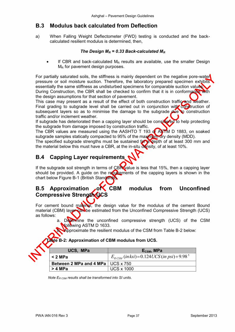
B.5 Approximation of CBM modulus from Unconfined Compressive Strength UCS For cement bound material, the design value for the modulus of the cement Bound material (CBM) layer can be estimated from the Unconfined Compressive Strength (UCS) as follows:
a. Determine the unconfined compressive strength (UCS) of the CSM following ASTM D 1633.
b. Approximate the resilient modulus of the CSM from Table B-2 below:
Table B-2: Approximation of CBM modulus from UCS.
UCS, MPa ECSM, MPa
< 2 MPa ( ) 0.124 ( ) 9.98R CSME inksi UCS in psi 1
Between 2 MPa and 4 MPa UCS x 750
> 4 MPa UCS x 1000 Note ER CSM results shall be transformed into SI units.

Ashghal – Pavement Design Guidelines
PWA IAN 016 Rev 3 Page 38 September 2013
Figure B-1: A guide chart shows when capping/sub base layers are required (British Standards).
B.6 Practical guidelines in pavement design Practices in pavement design have reached some general conclusions when designing and building a road on a subgrade of a certain CBR value. For example, it is not a good practice to build on a layer when the CBR value is less than 15%. It is necessary to improve this value either by capping or increasing the thickness of the sub-base.
For subgrade with CBR values of 15% and above, the sub-base should have a standard thickness of 150mm, a value determined as the minimum practical for spreading and compaction.
For subgrade with CBR values in excess of 30% and a low water table or hard rock subgrade, then the sub-base may be omitted.
In cases where rock layer is encountered, this layer shall be maintained undisturbed and not to be dug into more than 10 cm (i.e. Surface scarifying) unless otherwise instructed by the Engineer.
When designing a road of some length, it is not advisable to frequently vary the foundation thickness but rather select an appropriate value for only significant changes in the subgrade properties.
Ashghal – Pavement Design Guidelines
PWA IAN 016 Rev 3 Page 39 September 2013
Appendix C – Materials Proper design of flexible pavements, particularly those pavements subjected to heavy traffic and environmental effects, such as temperature and rainfall effects require an extensive expertise and thorough understanding of the important characteristics of the materials of which the pavement is to be composed and on which it is to be founded.
C.1 Characteristics In principle, the following main physical and engineering characteristics are required: 1. Asphalt Layer properties represented mainly by its stability and stiffness. It is very
important to know that the stiffness characteristics of the asphalt mixtures are dependent on the time of loading and temperature. The asphalt mixture tends to be less stiff under high temperatures and high stress levels.
2. Granular Base and Subbase properties represented by its gradation, bearing strength (shear strength and or repeated load properties). The same material is used for both base and subbase layers and may consist of either crushed stone or gravel, or natural gravel, or a mixture of both. Aggregate hardness, durability, abrasion resistance, cleanliness, grading, absorption, shape and strength requirements, given in the Specifications, must be met.
The material must achieve a CBR value of equal to or above 80% for road base and equal to or above 60% for subbase when compacted to 100% of the maximum dry density (MDD) as determined using the AASHTO T 193 or ASTM D 1883. 100% relative density shall be achieved in the field. The minimum layer thickness of base or subbase layer shall not be less than 150 mm.
3. Stabilised or treated bases represented by its compressive and flexural strength and repeated load properties such as fatigue properties. The cement bound material may have a fairly wide grading envelope and may consist of, any or all of, sand, gravel or crushed rock. The material is mixed with cement either in-place or in an off-road mixer
4. Subgrade properties represented by the strength or stability of the subgrade soil, classification, other chemical and organic properties in addition to repeated load properties. The CBR values are measured using the AASHTO T 193 or ASTM D 1883, on soaked subgrade samples statically compacted to 95% of the maximum dry density (MDD).
The specified subgrade strengths must be sustained for a depth of at least 300 mm and the material below this must have a CBR, at the in-situ density, of at least 10%. This can be easily confirmed using a simple hand operated Dynamic Cone Penetrometer (Kleyn and Savage, 1982). Where the above conditions are not met, either some of the subgrade material must be replaced with higher quality material, and then, the upper 300 mm of the subgrade is stabilized in accordance with subgrade stabilization methods, then apply a cover materials, or consider detailed design approach after discussion with the PWA. The necessary replacement or cover thickness can be determined on the basis of providing the same stiffness at the formation level (top of the earthworks). The proposals for non-standard subgrade situations must be discussed with the Engineer for final design arrangements.
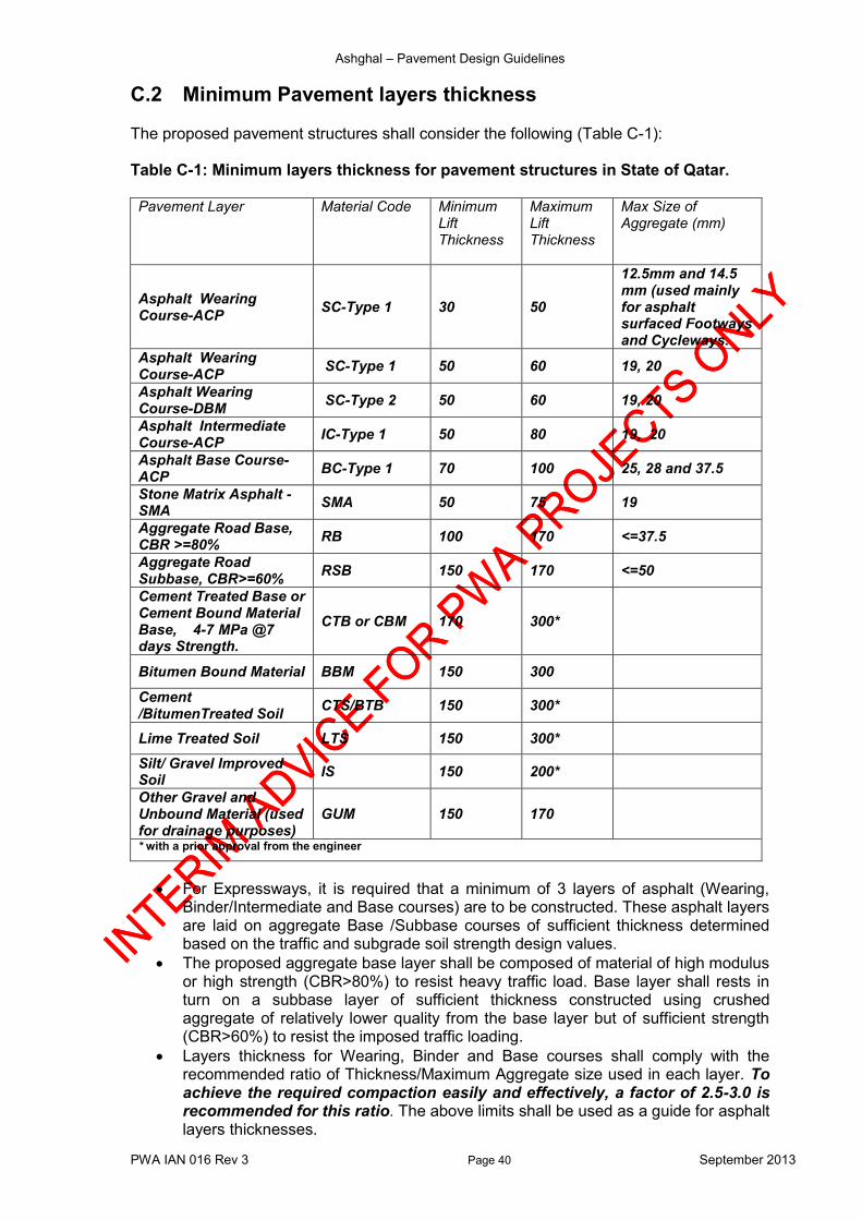
Ashghal – Pavement Design Guidelines
PWA IAN 016 Rev 3 Page 40 September 2013
C.2 Minimum Pavement layers thickness The proposed pavement structures shall consider the following (Table C-1): Table C-1: Minimum layers thickness for pavement structures in State of Qatar. Pavement Layer Material Code Minimum
Lift Thickness
Maximum Lift Thickness
Max Size of Aggregate (mm)
Asphalt Wearing Course-ACP
SC-Type 1 30 50
12.5mm and 14.5 mm (used mainly for asphalt surfaced Footways and Cycleways.
Asphalt Wearing Course-ACP
SC-Type 1 50 60 19, 20
Asphalt Wearing Course-DBM
SC-Type 2 50 60 19, 20
Asphalt Intermediate Course-ACP
IC-Type 1 50 80 19, 20
Asphalt Base Course-ACP
BC-Type 1 70 100 25, 28 and 37.5
Stone Matrix Asphalt - SMA
SMA 50 75 19
Aggregate Road Base, CBR >=80%
RB 100 170 <=37.5
Aggregate Road Subbase, CBR>=60%
RSB 150 170 <=50
Cement Treated Base or Cement Bound Material Base, 4-7 MPa @7 days Strength.
CTB or CBM 170 300*
Bitumen Bound Material BBM 150 300
Cement /BitumenTreated Soil
CTS/BTB 150 300*
Lime Treated Soil LTS 150 300*
Silt/ Gravel Improved Soil
IS 150 200*
Other Gravel and Unbound Material (used for drainage purposes)
GUM 150 170
* with a prior approval from the engineer
For Expressways, it is required that a minimum of 3 layers of asphalt (Wearing, Binder/Intermediate and Base courses) are to be constructed. These asphalt layers are laid on aggregate Base /Subbase courses of sufficient thickness determined based on the traffic and subgrade soil strength design values.
The proposed aggregate base layer shall be composed of material of high modulus or high strength (CBR>80%) to resist heavy traffic load. Base layer shall rests in turn on a subbase layer of sufficient thickness constructed using crushed aggregate of relatively lower quality from the base layer but of sufficient strength (CBR>60%) to resist the imposed traffic loading.
Layers thickness for Wearing, Binder and Base courses shall comply with the recommended ratio of Thickness/Maximum Aggregate size used in each layer. To achieve the required compaction easily and effectively, a factor of 2.5-3.0 is recommended for this ratio. The above limits shall be used as a guide for asphalt layers thicknesses.
Ashghal – Pavement Design Guidelines
PWA IAN 016 Rev 3 Page 41 September 2013
If different gradation of base and sub-base with maximum aggregate size other than limits specified, the designer has to apply this factor to determine the limits of asphalt layers thicknesses.
C.3 Pavement layer extent
Base extent - For kerbed roads, the base and asphalt surfacing shall extend to the face of any
kerbing and/or guttering. - Where the top surface of the subbase layer is below the level of the underside of
the kerbing and/or guttering, the base layer shall also extend a minimum of 150mm behind the rear face of the kerbing and/or guttering.
- For un-kerbed roads, the base layers shall extend at least to the nominated width of shoulder.
a) Subbase extent - For kerbed roads, the subbase layer shall extend a minimum of 150mm behind the
back of any kerbing and/or guttering. - For un-kerbed roads, the subbase layers shall extend at least to the nominated
width of shoulder. b) Shoulder design
- Typically, paved shoulders have a pavement structural capacity less than the mainline; however, this is dependent on the roadway. For Major routes, the pavement shoulder shall have the same design as the mainline pavement. This will allow the shoulder to support extended periods of traffic loading as well as provide additional support to the mainline structure.
- A full-depth shoulder (same design as the mainline pavement) is also recommended for other high-volume urban routes.
- Inner shoulders are proposed to be designed to the full design thickness for the future widening purposes.
- Outer shoulders are proposed to be designed to the full design thickness for the future widening purposes.
A minimum of two AC layers must be designed for the shoulder in order to provide edge support for the mainline pavement structure. The AC layers must be placed on an aggregate or cement stabilized aggregate layer, not directly on subgrade, to provide adequate support and drainage for the shoulder structure.

Ashghal – Pavement Design Guidelines
PWA IAN 016 Rev 3 Page 42 September 2013
Appendix D – Employer’s Minimum Requirements for Design and Build (D&B) Projects For all expressways tendered as Design and Build (D&B) projects, the following minimum employer’s requirements shall be considered: 1. The Contractor shall provide a balanced pavement structure in accordance with the
Employer’s Requirements (as set out in the latest revision of IAN16 and IAN19) that is technically valid to withstand the predicted traffic.
2. The Contractor shall base their pavement design calculations on the predicted traffic demand flows up to 2031. All traffic volumes are provided in the updated QSTM-1.0.
3. In addition to Clause 2, the Contractor shall use a compound annual growth factor of
5% from 2031 to 2036 to estimate the Design ESAL for the pavement design life in accordance with the Employer’s Requirements.
4. The % of Heavy Vehicle (% HV) and the proportions of various truck classes shall be
extracted from: a. The tender documents, if given. b. Figure 7-1 included in the MMUP document entitled “Guidelines and Procedures
for Transport Studies, 2012. This figure can be used to estimate %HV till the year 2018. From the year 2018 to the year 2031, the % HV and the proportions of various heavy vehicles classes shall be extracted from Qatar Strategic Traffic Model (QSTM 1.0 or the latest version).
c. Bidders’ estimation, if a reliable traffic data / traffic count is available, with full justification.
5. Truck factors for classified traffic to be used in pavement design shall be calculated based on actual loading through Weigh In Motion (WIM) survey if any. Alternatively, the following indicative figures can be used:
Class Truck factor
Busses/pick ups 0.58
Light trucks 1.5
Heavy trucks 6.0
6. In cases where traffic classification is not available for calculating the Design ESAL, the average ESAL per Heavy Vehicle must be not less than 2.6.
7. The Adopted Design ESAL shall be the maximum of: a. the Design ESAL calculated in accordance with Clauses 2 to 4 above and the
Employer’s Requirements; and b. the minimum ESAL listed in the following table:
Pavement Location Minimum Design ESAL
Separate truck lanes 25 Million
Main carriageway and cross roads without separate adjacent truck lanes
25 Million
Main carriageway and cross roads where there are adjacent separate truck lanes
15 Million or 10% of the Design ESAL for the adjacent truck lanes, whichever is greater
Loops and ramps without separate adjacent truck lanes
15 Million
Loops and ramps where there are separate adjacent truck lanes
10 Million
Ashghal – Pavement Design Guidelines
PWA IAN 016 Rev 3 Page 43 September 2013
8. Notwithstanding the calculated thickness of asphalt, the maximum total asphalt thickness in any pavement must not exceed 320 mm.
9. The thickness of any granular base or subbase layer must not exceed 350 mm. 10. Cement Stabilized Material (CBM2) with Compressive strength @7 days of value in
the range (4-7 MPa) shall only be considered as an alternative option to Unbound material in order to reduce the pavement structure overall thickness if required. The thickness of the CBM layer shall range from 150 mm to 250 mm. A typical CBM layer thickness of 200 mm is recommended to be used.
11. In cases where CBM is used in pavement structure, a subbase layer of a minimum
thickness of 150 mm shall be used for constructability purposes. 12. Material specifications shall be in accordance with latest revision of Qatar Construction
Specification- QCS and latest revision of IAN 019- Amendment to QCS. 13. Pavement design inputs and material characterization values (Asphalt, Aggregate
base and aggregate subbase) shall be within the limits outlined in latest revision of IAN 16. Other values can be used if found necessary with sufficient justification.
14. The lift thickness of different asphalt layers (AC Wearing Course, AC Intermediate and
AC Base Course) shall be within the limits outlined in latest revision of QCS and IAN 019.
15. Polymer Modified Bitumen (PMB) (that is asphalt performance grade PG76-10 S, H, V
& E, as per IAN 019) shall be used in the top two (2) layers of pavement. The top two layers shall consist of a minimum of 50mm PMB wearing course plus a minimum of 70mm PMB intermediate course for a total PMB minimum thickness of 120mm. The selection of PMB grade PG76-10 S, H, V or E shall be based on design traffic level in terms of ESAL and in accordance with guidelines outlined in Table 5.12 of IAN 019 (latest revision) or QCS if any.
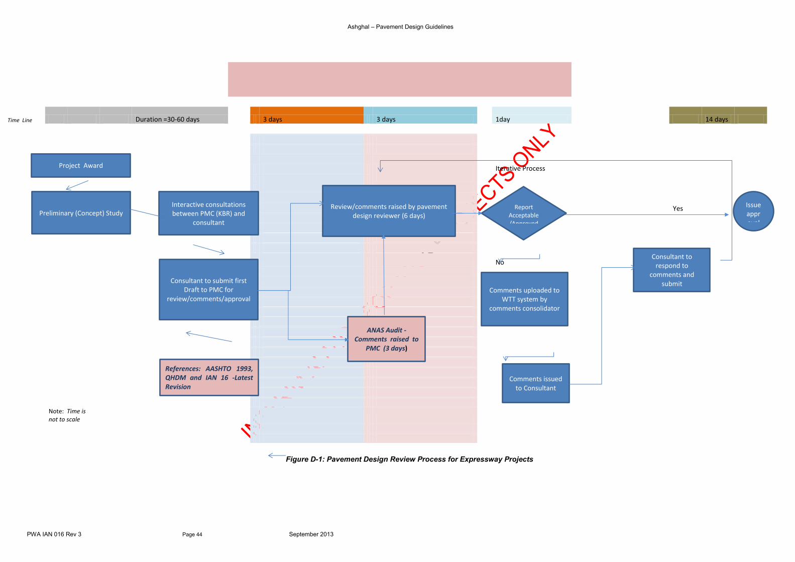
Ashghal – Pavement Design Guidelines
PWA IAN 016 Rev 3 Page 44 September 2013
Figure D-1: Pavement Design Review Process for Expressway Projects
Time Line
Duration =30-60 days
3 days 3 days
1day
14 days
Iterative Process
Yes
New Gateway
No
Note: Time is not to scale
Project Award
Consultant to submit first Draft to PMC for
review/comments/approval
Preliminary (Concept) Study Interactive consultations between PMC (KBR) and
consultant
Comments issued to Consultant
Comments uploaded to WTT system by
comments consolidator
Review/comments raised by pavement design reviewer (6 days)
ANAS Audit -Comments raised to
PMC (3 days)
Consultant to respond to
comments and submit
Report Acceptable/Approved
Issue approval Lette
r throu
gh WTT syste
m
References: AASHTO 1993, QHDM and IAN 16 -Latest Revision
Ashghal – Pavement Design Guidelines
PWA IAN 016 Rev 3 Page 45 September 2013
END