Embed Size (px)
Citation preview
INTRODUCTION
Terraforce & Terravert are a cost effective, segmented and mortarless retaining system which is fullly
interlocking and truly plant supportive. The unit by itself or in combination with other products in the
Terraforce range offers the designer unlimited creativity, structural integrity and continuing aesthetic
appeal. The systems comprise of versatile, reversible units that can effectively be used in the
planning of virtually all erosion control, landscaping and even heavy earth retaining projects.
FEATURES
Sharp or wide, convex or concave curves are formed by simply turning the units without eliminating
the interlocking feature. By reversing the elements, flat faced structures such as steps or vertical
flush faced retaining walls and free standing walls may be built. The units that have been filled with
topsoil can be planted with creepers, ground covers, shrubs or flowers.
DESIGN AND SPECIFICATION
The success of any construction project depends on:
a) professional design
b) quality materials
c) good construction techniques
A. PROFESSIONAL DESIGN
This guide is intended to provide on-site installation guidelines and ideas only. For Engineering
details on the following vital design considerations, please consult a registered qualified engineer
who has our comprehensive design manual.
- Safe wall inclinations for final height and fill slope
- Inspection of Ground conditions
- Calculation of wall loading conditions
- Foundation specification
- Engineered Backfilling materials and technique
- Drainage surface and subsurface collection & direction
A separate calculation and specification will be necessary for site conditions not covered within the
scope of the design manual.
3
B. QUALITY MATERIAL
Terraforce elements are machine made to exacting standards by leading manufacturers of
concrete products on three continents. They have been thoroughly tested and researched under
field and laboratory conditions, backed up by substantially engineered design manuals. This aspect,
combined with unmatched versatality, cost effectiveness and aesthetic appeal, make Terraforce the
best retaining walls system available. Blocks are manufactured generally in compliance with SANS
508:2008
4
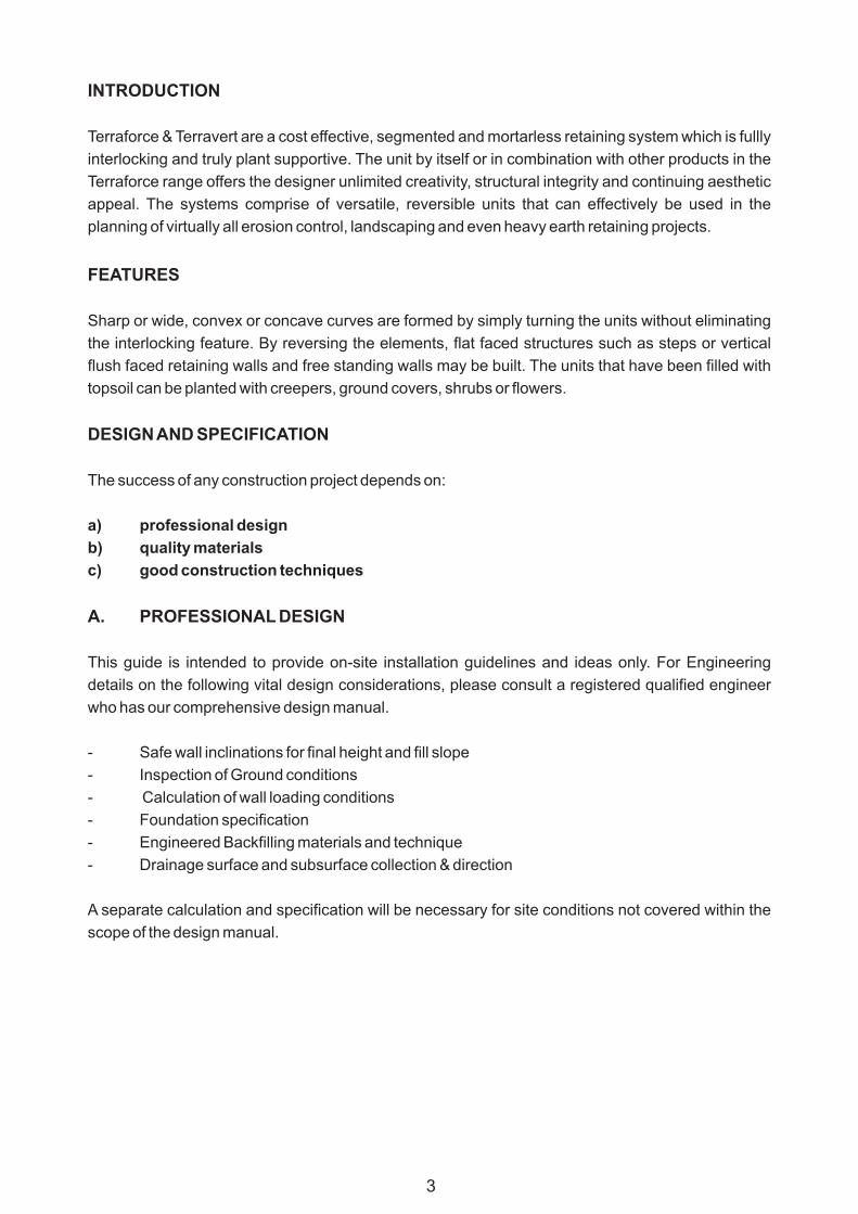
TYPICAL TERRAVERT WALL PROFILE 3500MM HIGH
TERRAVERT V8-320 BLOCKS AT 65°
ROCK GRID
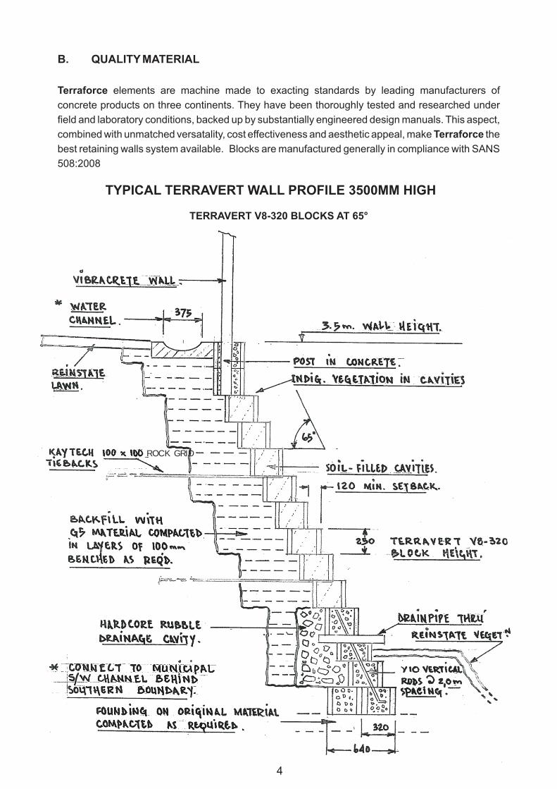
FOUNDATIONS
Prepare a level foundation, compacted earth, subbase of concrete as directed to suit site
conditions. The top of finished foundation level should be at least 150mm below natural
ground level. Compacted earth foundations are usually sufficient for structures not higher
than 1,5metres. When poor ground conditions occur or higher walls are to be built, please
consult your local supplier with regard to foundation details. On sloping sites, the foundation
may be stepped in intervals to suit the height of units. (SEE ILLUSTRATION ABOVE) Note:
No Services and trenches are to be permitted immediately in front of the foundation.
5
STEPPED FORWARD & UP
FOUNDATION DETAIL
STEPPED BACK & UP
ALTERNATIVE FOUNDATION DETAIL
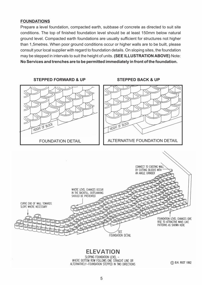
INSTALLATION
Always start laying units at the lowest point, where a stepped foundation occurs. Ensure that
the first row of units is accurately aligned and each block is absolutely level. (Use builders
line and level). When placed on a set concrete foundation, a small amount of mortar under
each unit of the bottom row will facilitate accurate levelling. Proceed to dry stack further
layers of Terraforce, stepping back as designed while constantly checking on levels and
alignment, prepare compacted bed with hoe-head and use a 4LB hammer tamping with the
wooden handle to humour blocks to bond and level.
It is common practice to lay units in a offset stretcher bond fashion, however in some
instances stack bond may be more suitable or will occur within curved structures. An angle
grinder is most suitable for cutting elements, should this become necessary.
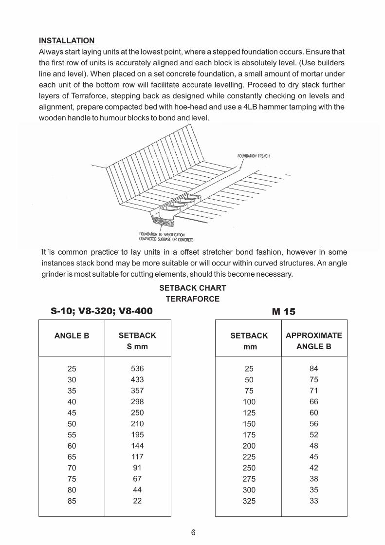
SETBACK CHART
TERRAFORCE
ANGLE B
25
30
35
40
45
50
55
60
65
70
75
80
85
SETBACK
mm
25
50
75
100
125
150
175
200
225
250
275
300
325
SETBACK
S mm
536
433
357
298
250
210
195
144
117
91
67
44
22
APPROXIMATE
ANGLE B
84
75
71
66
60
56
52
48
45
42
38
35
33
S-10; V8-320; V8-400 M 15
6
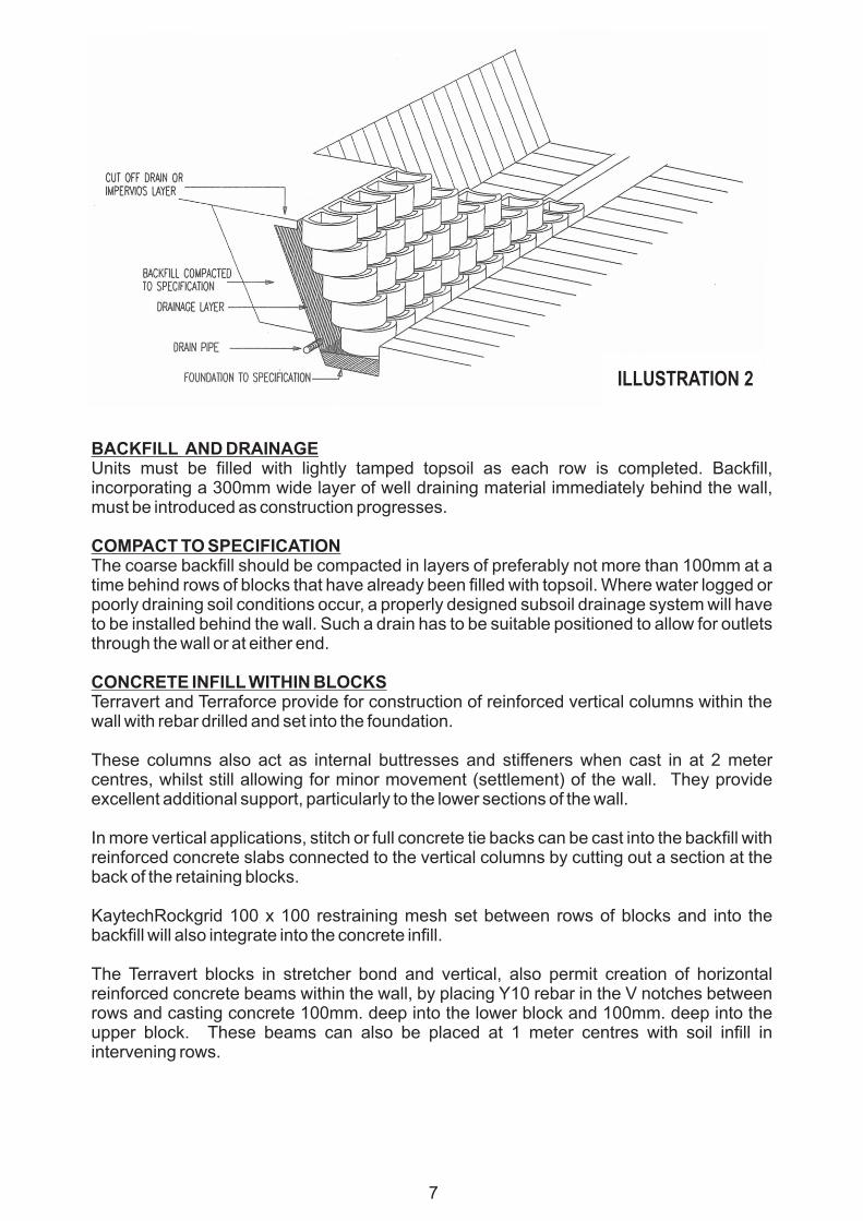
BACKFILL AND DRAINAGEUnits must be filled with lightly tamped topsoil as each row is completed. Backfill, incorporating a 300mm wide layer of well draining material immediately behind the wall, must be introduced as construction progresses.
COMPACT TO SPECIFICATIONThe coarse backfill should be compacted in layers of preferably not more than 100mm at a time behind rows of blocks that have already been filled with topsoil. Where water logged or poorly draining soil conditions occur, a properly designed subsoil drainage system will have to be installed behind the wall. Such a drain has to be suitable positioned to allow for outlets through the wall or at either end.
CONCRETE INFILL WITHIN BLOCKSTerravert and Terraforce provide for construction of reinforced vertical columns within the wall with rebar drilled and set into the foundation.
These columns also act as internal buttresses and stiffeners when cast in at 2 meter centres, whilst still allowing for minor movement (settlement) of the wall. They provide excellent additional support, particularly to the lower sections of the wall.
In more vertical applications, stitch or full concrete tie backs can be cast into the backfill with reinforced concrete slabs connected to the vertical columns by cutting out a section at the back of the retaining blocks.
KaytechRockgrid 100 x 100 restraining mesh set between rows of blocks and into the backfill will also integrate into the concrete infill.
The Terravert blocks in stretcher bond and vertical, also permit creation of horizontal reinforced concrete beams within the wall, by placing Y10 rebar in the V notches between rows and casting concrete 100mm. deep into the lower block and 100mm. deep into the upper block. These beams can also be placed at 1 meter centres with soil infill in intervening rows.
7
ILLUSTRATION 2
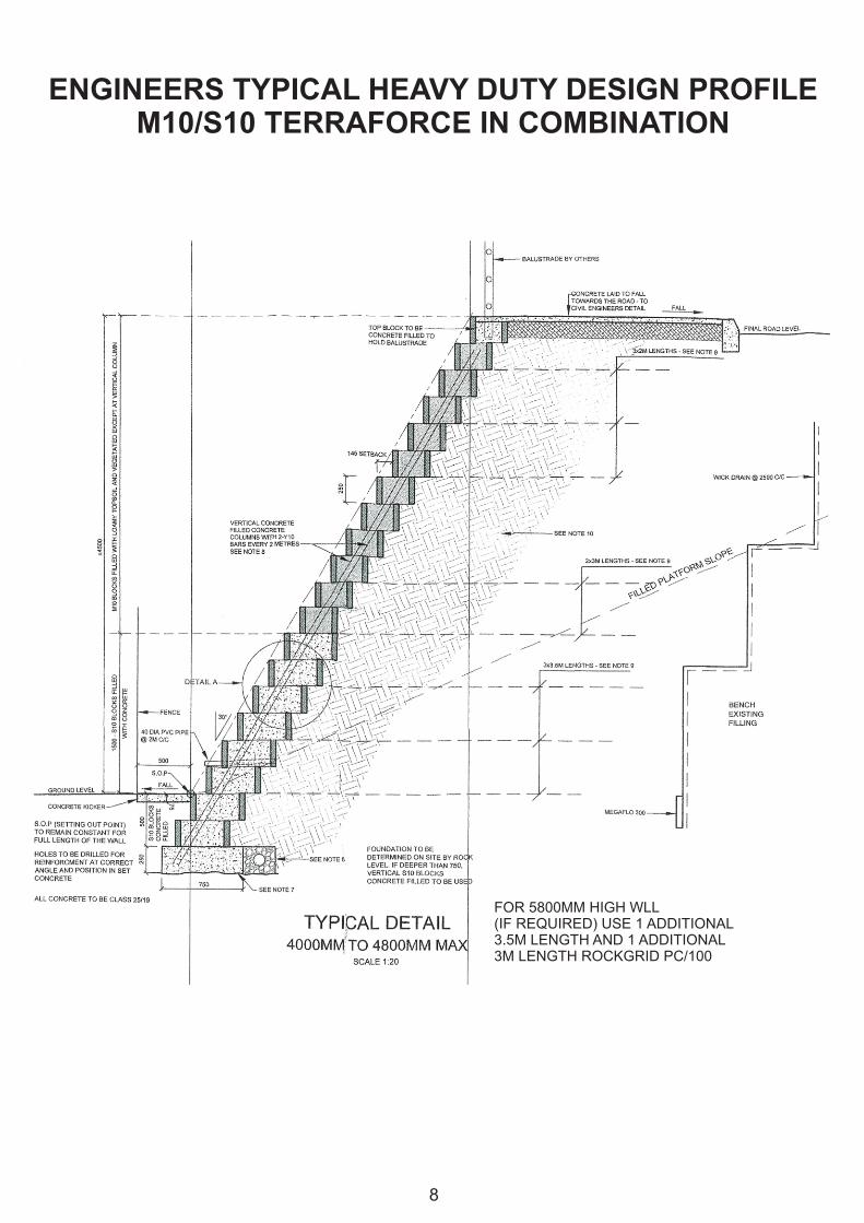
ENGINEERS TYPICAL HEAVY DUTY DESIGN PROFILEM10/S10 TERRAFORCE IN COMBINATION
8
FOR 5800MM HIGH WLL(IF REQUIRED) USE 1 ADDITIONAL3.5M LENGTH AND 1 ADDITIONAL3M LENGTH ROCKGRID PC/100