Embed Size (px)
Citation preview

B E A C H E S . M A R I N A S . D E S I G N . C O N S T R U C T I O N .
OECS Regional Engineering Workshop September 29 – October 3, 2014
Coastal Erosion and Sea Defense:
Introduction to Coastal/Marine Structures
David A Y Smith

OUTLINE
• COASTAL EROSION PREVENTION APPROACHES (HARD/SOFT)
– Revetments, groynes, breakwaters, jetties
– Beaches, dunes
• DESIGN CONSIDERATIONS
– Armour stability, overtopping, scour, residual life
– Level of risk to be adopted by implementing agencies

REFERENCE MATERIAL
• COASTAL ENGINEERING MANUAL – US ARMY CORPS OF ENGINEERS
• CIRIA ROCK MANUAL (1991, 2007)

COASTAL ENGINEERING MANUAL (CEM)
– Started as the Shore Protection Manual
– Edited every 7 years (1977, 1984, etc.)
– Significantly expanded over the years
– Now available online in two forms
• Free pdf version
• Interactive form (available for purchase through Veri-tech Inc.)
CIRIA ROCK MANUAL
• FIRST EDITION 1991
• SECOND LARGER EDITION 2007
• CREATED IN EUROPE
• AVAILABLE ONLINE (FREE) HTTP://WWW.FILESTUBE.TO/CM1QPB4BDU123RE1SJNCBF

MANUALS
• CEM AND CIRIA – LARGE, COMPREHENSIVE DOCUMENTS
• SIMILARITIES AND DIFFERENCES
– Written and edited by large working groups
– Regularly updated with current research
– CIRIA 2nd Ed. is more prescriptive
– CEM includes chapters on ancillary aspects

COASTAL STRUCTURES
• PURPOSES:
– Prevent/reduce coastal erosion or flooding
– Protect harbours or channels
– Provide a buffer against natural disasters caused by hurricanes and tsunami
– Regain lost land through reclamation

COASTAL EROSION AND FLOODING
• THEY ACT AS BARRIERS
– Revetments, breakwaters, seawalls (Hard structures)
– Beach nourishment (“Soft” structure)
• HARNESS “FORCES OF NATURE” TO CREATE A BARRIER
– Groynes, offshore breakwaters
– Dune creation

HARBOUR & CHANNEL PROTECTION
• WAVE SHELTERING
– Breakwaters, jetties
• SEDIMENT TRAINING
– Groynes, offshore breakwaters

PROVIDE A BUFFER
• THROUGH PROVISION OF A SACRIFICIAL SHORELINE
– Beaches (and beach nourishment), dunes
• THROUGH PROVISION OF A HARD EDGE
– Groynes, revetments, seawalls, offshore breakwaters

LAND RECLAMATION
• WHERE FLAT LAND FOR DEVELOPMENT IS AT A PREMIUM
– Dredging, coupled with land reclamation
• TO SATISFY DEVELOPMENT REQUIREMENTS
– Creation of ports, industrial areas, etc.

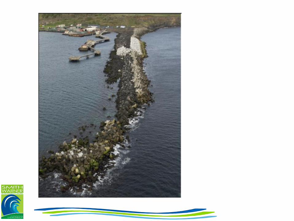
BARRIERS - REVETMENT

BARRIERS - SEAWALL
EM 1110-2-1100 (Part VI)
1 Jun 06
Types and Functions of Coastal Structures VI-2-11
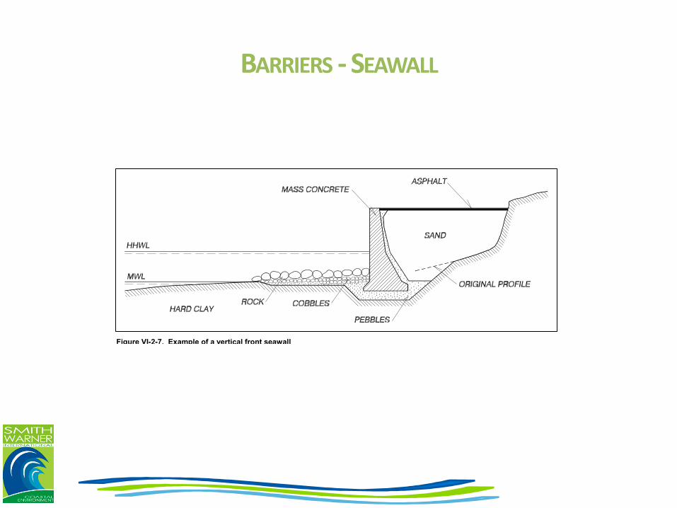
Figure VI-2-7. Example of a vertical front seawall
Figure VI-2-8. Typical beach configuration with groins
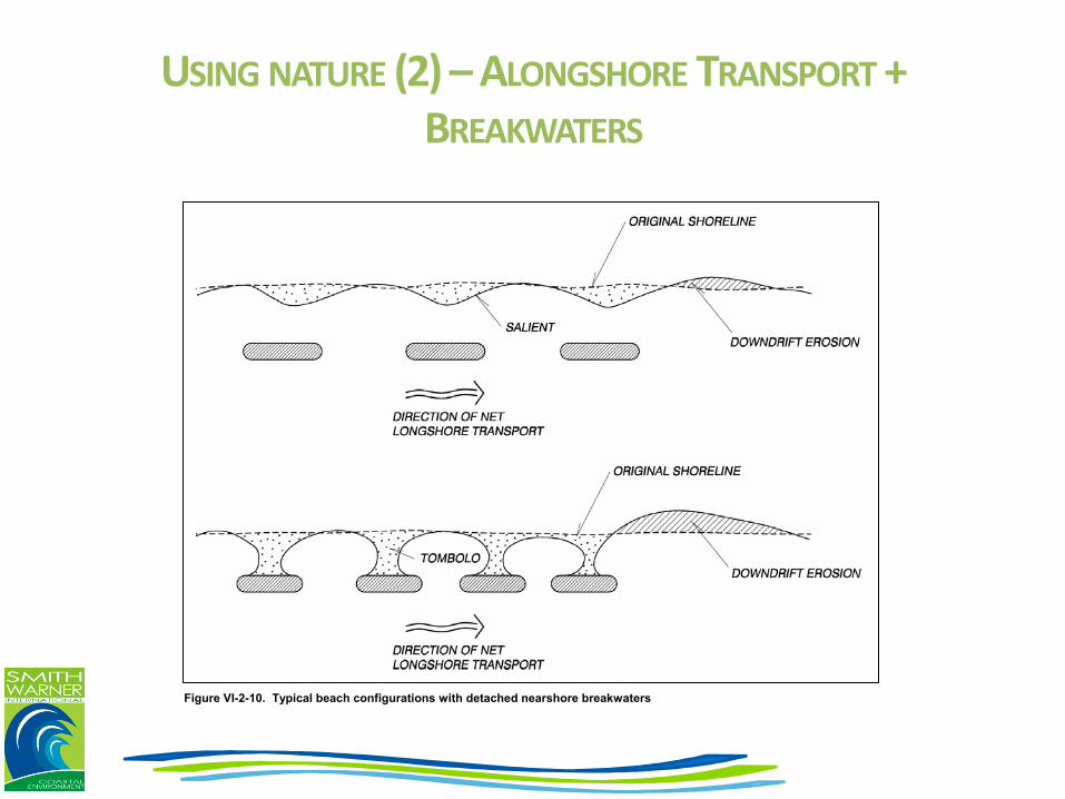
d. Detached breakwaters. Detached breakwaters are almost always built as rubble-mound structures.
Typical cross sections are as shown for the rubble-mound groin in Figure VI-2-9. Typical beach configu-
rations with detached nearshore breakwaters are shown in Figure VI-2-10. Whether or not the detached
breakwaters become attached to shore is a function of placement distance offshore. Tombolos are more likely
to form when breakwaters are constructed within the surf zone. The two examples of detached breakwaters
shown in Figure VI-2-10 serve different functions. See Part V-4 for functional design guidance on detached
breakwaters.

BREAKWATERS
EM 1110-2-1100 (Part VI)
1 Jun 06
Types and Functions of Coastal Structures VI-2-13
Figure VI-2-10. Typical beach configurations with detached nearshore breakwaters
Figure VI-2-11. Conventional multilayer rubble-mound breakwater
The front slope of the armor layer is in most cases straight. However, an S-shaped front or a front with a
horizontal berm might be used to increase the armor stability and reduce overtopping. For these types of
structures, optimization of the profiles might be difficult if there are large water level variations. Fig-
ure VI-2-12 illustrates these types of front profiles.
Overtopping can be reduced by a wave-wall superstructure as shown in Figure VI-2-13.


EM 1110-2-1100 (Part V)
1 Aug 08 (Change 2)
Shore Protection Projects V-3-73
Figure V-3-30. Westhampton Beach, New York, groin field and renourished beach, 1998 (courtesy
USAED, New York)
(d) Terminal groins. Groins on the updrift side of inlets can benefit nearby beach nourishment projects
by controlling (or gating) the amount entering (lost) to the inlet. These terminal structures also benefit
navigation projects by reducing the sediment rates within the inlet. They normally are impermeable and high
and long to prevent sand from being carried through, over, or around them. Eventually, they will fill and sand
bypassing around the end will be maintained. It should be noted that terminal groins are short compared with
the length of navigation jetties constructed to reduce wave heights for ships entering the inlet. Consequently,
the scale of interruption of normal, longshore sediment transport processes for ebb-and flood- tidal shoals
are far different for navigation jetties. Terminal groins fill quickly and do not have major impacts on ebb-
tidal shoals and normal, inlet, sand-passing processes. A successful terminal groin is that located on
the southern bank of Oregon Inlet, North Carolina. Design and monitoring details are found in Overton
et al. (1992); Dennis and Miller (1993); Miller, Dennis, and Wutkowski (1996); and Joyner,
EM 1110-2-1100 (Part V)
1 Aug 08 (Change 2)
V-3-62 Shore Protection Projects
Westhampton Beach, Long Island, New York, 18 Jan 1980 (courtesy USAED, New York)
Figure V-3-24. Rubble-mound groin, Westhampton Beach, New York
GROYNES + BEACH NOURISHMENT

USING NATURE – ALONGSHORE TRANSPORT + GROYNES
EM 1110-2-1100 (Part VI) 1 Jun 06
Types and Functions of Coastal Structures VI-2-11
Figure VI-2-7. Example of a vertical front seawall
Figure VI-2-8. Typical beach configuration with groins
d. Detached breakwaters. Detached breakwaters are almost always built as rubble-mound structures.
Typical cross sections are as shown for the rubble-mound groin in Figure VI-2-9. Typical beach configu-
rations with detached nearshore breakwaters are shown in Figure VI-2-10. Whether or not the detached
breakwaters become attached to shore is a function of placement distance offshore. Tombolos are more likely
to form when breakwaters are constructed within the surf zone. The two examples of detached breakwaters
shown in Figure VI-2-10 serve different functions. See Part V-4 for functional design guidance on detached
breakwaters.
USING NATURE (2) – ALONGSHORE TRANSPORT + BREAKWATERS
EM 1110-2-1100 (Part VI)
1 Jun 06
Types and Functions of Coastal Structures VI-2-13
Figure VI-2-10. Typical beach configurations with detached nearshore breakwaters
Figure VI-2-11. Conventional multilayer rubble-mound breakwater
The front slope of the armor layer is in most cases straight. However, an S-shaped front or a front with a
horizontal berm might be used to increase the armor stability and reduce overtopping. For these types of
structures, optimization of the profiles might be difficult if there are large water level variations. Fig-
ure VI-2-12 illustrates these types of front profiles.
Overtopping can be reduced by a wave-wall superstructure as shown in Figure VI-2-13.

OFFSHORE BREAKWATERS EM 1110-2-1100 (Part V)
1 Aug 08 (Change 2)
Shore Protection Projects V-3-47
Figure V-3-19. Breakwater construction and salients; two views of Presque Isle, Pennsylvania (from Mohr
1994)

SAND DUNES

DESIGN CONSIDERATIONS
• ARMOUR STABILITY
• RUN-UP AND OVERTOPPING
• SCOUR PROTECTION
• FAILURE MODES
ARMOUR STABILITY
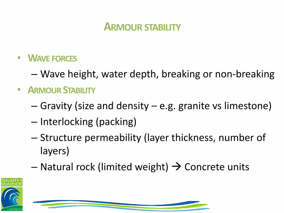
• WAVE FORCES
– Wave height, water depth, breaking or non-breaking
• ARMOUR STABILITY
– Gravity (size and density – e.g. granite vs limestone)
– Interlocking (packing)
– Structure permeability (layer thickness, number of layers)
– Natural rock (limited weight) Concrete units

PACKING OF BOULDERS
GRANITE VS. LIMESTONE
WAVE RUN-UP AND OVERTOPPING
– Safety of pedestrians, cars, infrastructure
– Inland flooding
– Can lead to structural failure

Q < 0.1 l/s/m for “aware” pedestrians


SCOUR PROTECTION
– Non-breaking wave forces high velocities
– Smaller armour stone sizes required
– Create an apron of immobile material

MODES OF FAILURE - BREAKWATER


EM 1110-2-1100 (Part VI)
1 Jun 06
Types and Functions of Coastal Structures VI-2-31
Figure VI-2-39. Toe instability on hard bottoms
Figure VI-2-40. Washout of underlayer material

EM 1110-2-1100 (Part VI)
1 Jun 06
Types and Functions of Coastal Structures VI-2-33
Figure VI-2-43. Scour due to overtopping
Figure VI-2-44. Toe erosion failure of rubble slope
Figure VI-2-45. Failure of sheet-pile toe wall


EM 1110-2-1100 (Part VI)
1 Jun 06
Types and Functions of Coastal Structures VI-2-43
Figure VI-2-64. Seaward overturning of gravity wall
Figure VI-2-65. Gravity wall settlement

SUMMARY
• RESOURCES
– CIRIA Rock Manual
– Coastal Engineering Manual
• PURPOSE OF COASTAL STRUCTURES
• DESIGN ASPECTS
• MODES OF FAILURE