Embed Size (px)
Citation preview
Introduction to Particle Accelerators: Part 2
Dr Graeme BurtLancaster University
New Frontier Challenges
Energy Frontier
Intensity Frontier
Brightness Frontier
Cockcroft PG Education 2015 M W Poole

Energy Frontier
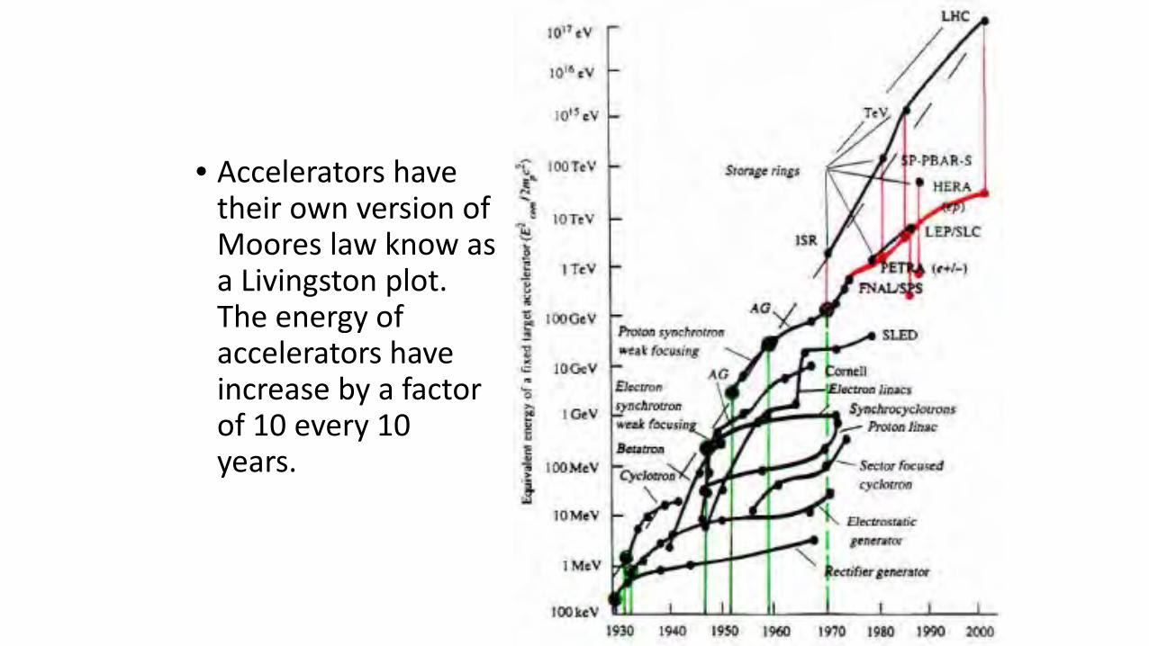
• Accelerators have their own version of Moores law know as a Livingston plot. The energy of accelerators have increase by a factor of 10 every 10 years.
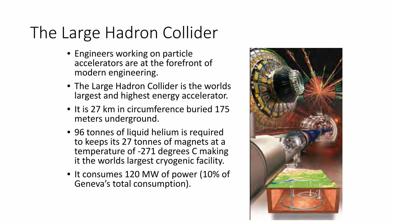
The Large Hadron Collider• Engineers working on particle
accelerators are at the forefront of modern engineering.
• The Large Hadron Collider is the worlds largest and highest energy accelerator.
• It is 27 km in circumference buried 175 meters underground.
• 96 tonnes of liquid helium is required to keeps its 27 tonnes of magnets at a temperature of -271 degrees C making it the worlds largest cryogenic facility.
• It consumes 120 MW of power (10% of Geneva’s total consumption).
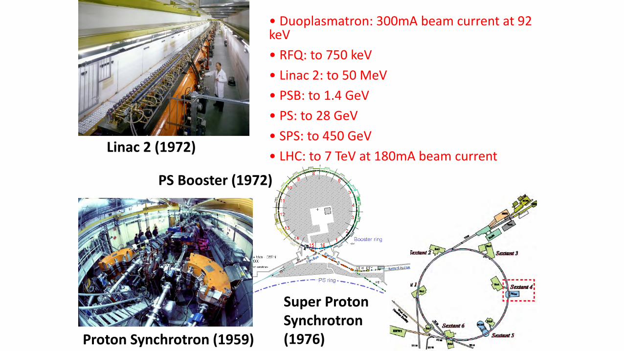
Linac 2 (1972)
PS Booster (1972)
Proton Synchrotron (1959)
Super Proton Synchrotron (1976)
• Duoplasmatron: 300mA beam current at 92 keV• RFQ: to 750 keV• Linac 2: to 50 MeV• PSB: to 1.4 GeV• PS: to 28 GeV• SPS: to 450 GeV• LHC: to 7 TeV at 180mA beam current
Limits to Proton Synchrotron Energy
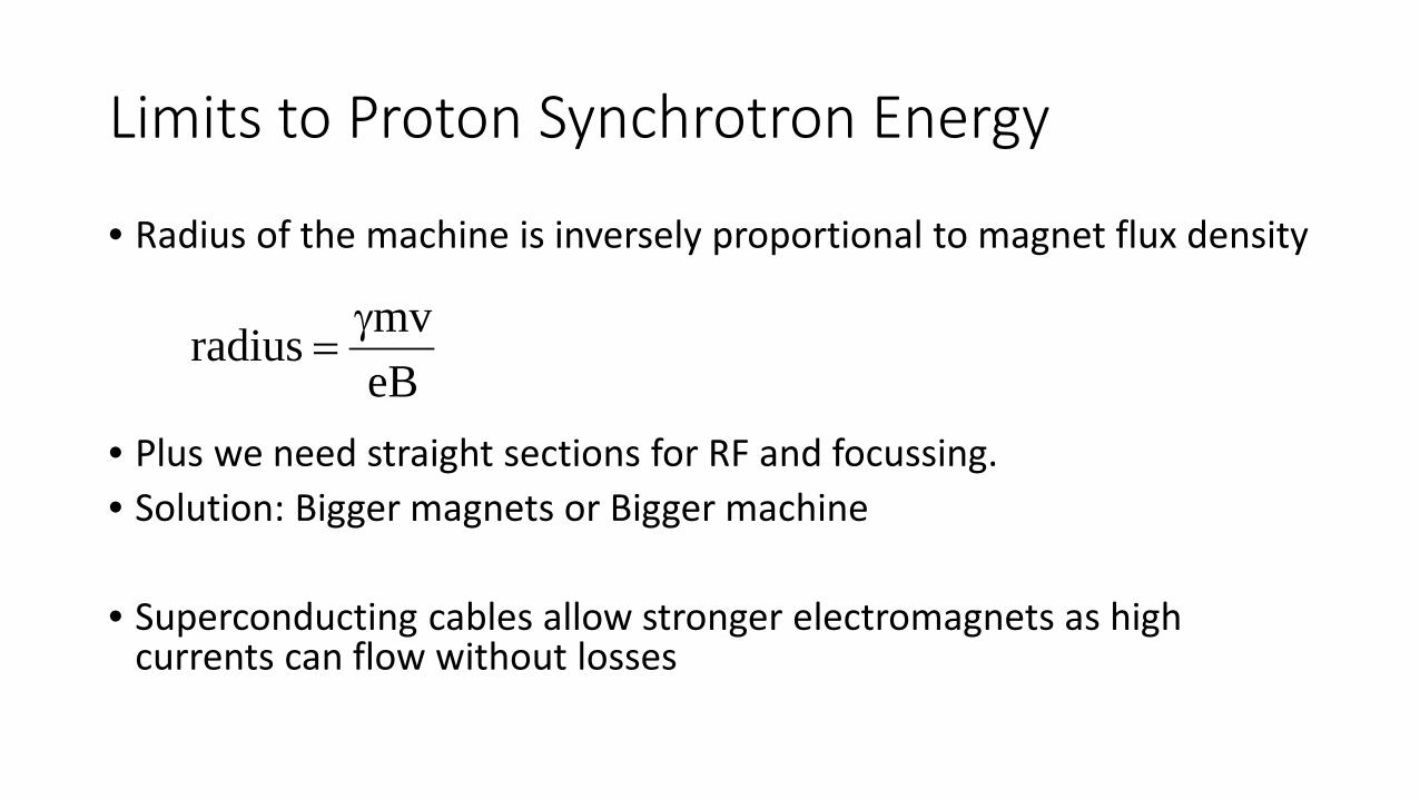
• Radius of the machine is inversely proportional to magnet flux density
• Plus we need straight sections for RF and focussing.• Solution: Bigger magnets or Bigger machine
• Superconducting cables allow stronger electromagnets as high currents can flow without losses
eBmvradius γ
=
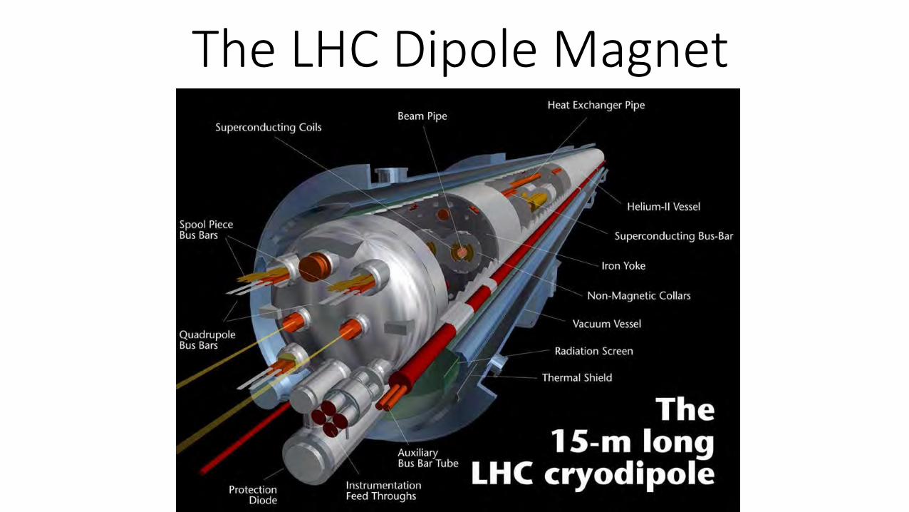
The LHC Dipole Magnet
Thermodynamic Critical Field• When electrons condence into cooper pairs the superconducting state
becomes more ordered than the normal conducting state and hence the free energy is lower.
• When an excternal magnetic field is applied to the superconductor, supercurrents flow to cancel the field and hence the free energy increases.
• When the external field rises to such a level, Hc, that the superconducting state and normal conducting state have an equal amount of free energy the states are in equilibrium.
• When the external field reaches Hc all the flux enters the superconductor. This is known as the thermodynamic critical field. It is around 200 mT for Nb.
• This also leads to a critical current density.
11
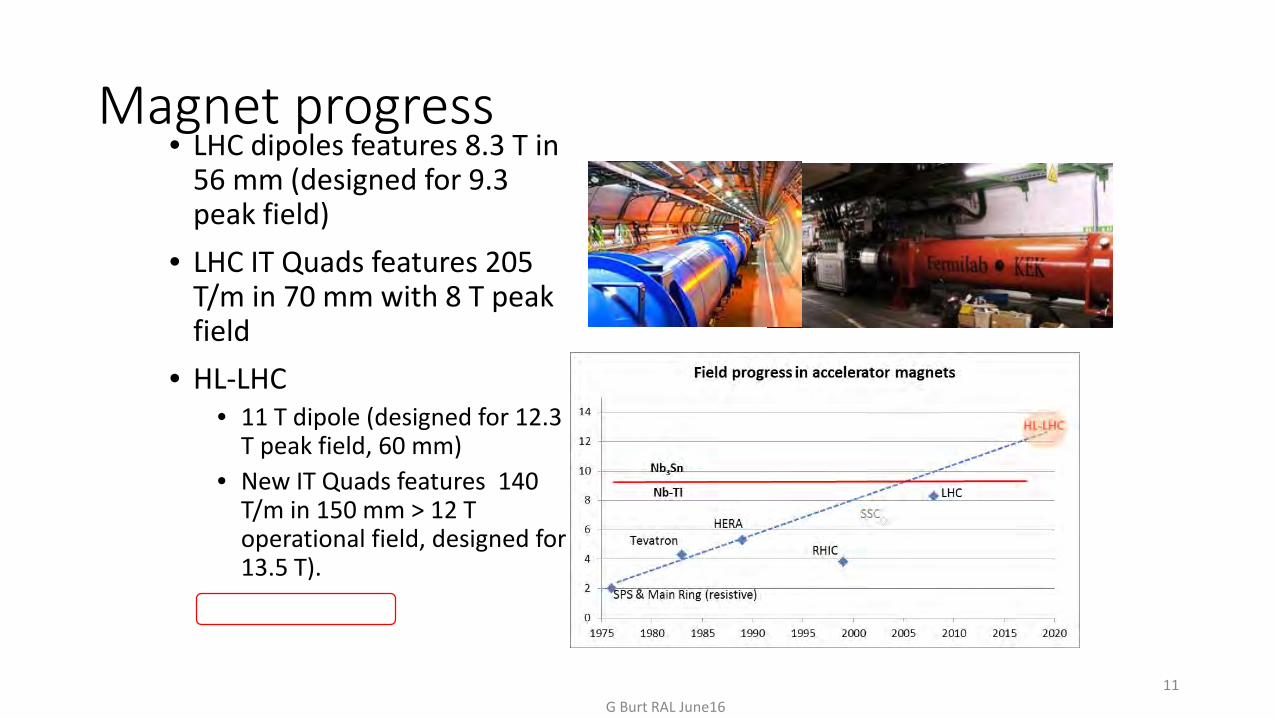
Magnet progress• LHC dipoles features 8.3 T in
56 mm (designed for 9.3 peak field)
• LHC IT Quads features 205 T/m in 70 mm with 8 T peak field
• HL-LHC • 11 T dipole (designed for 12.3
T peak field, 60 mm)• New IT Quads features 140
T/m in 150 mm > 12 T operational field, designed for 13.5 T).
G Burt RAL June16
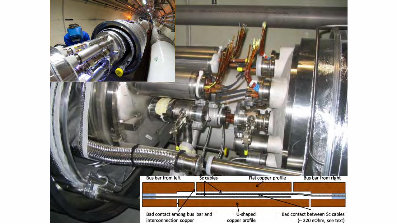
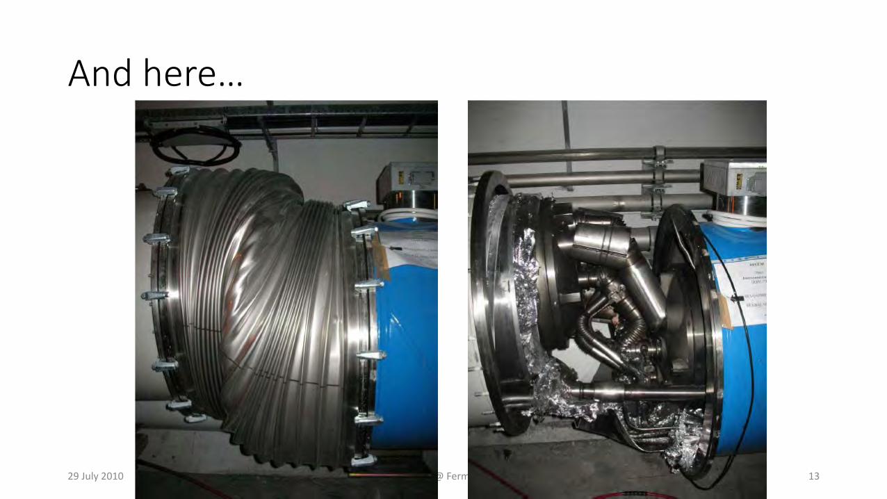
And here…
29 July 2010 L Rossi @ Fermilab 13
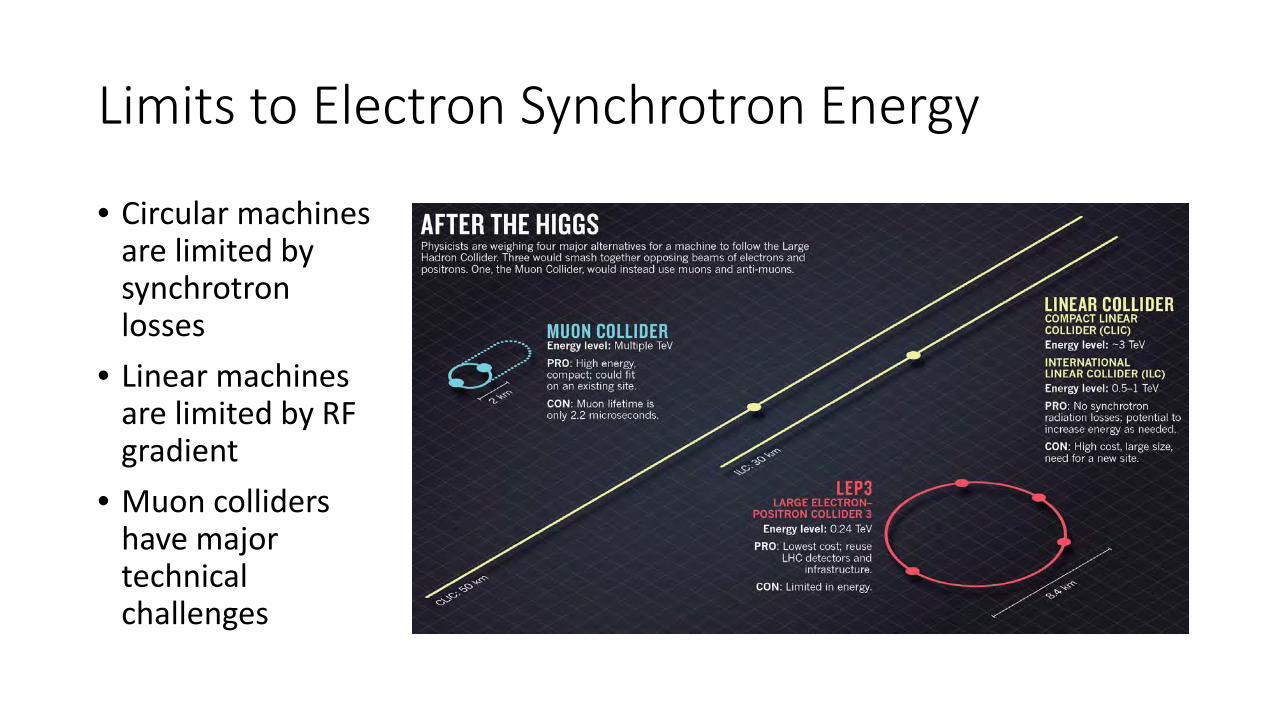
Limits to Electron Synchrotron Energy
• Circular machines are limited by synchrotron losses
• Linear machines are limited by RF gradient
• Muon colliders have major technical challenges
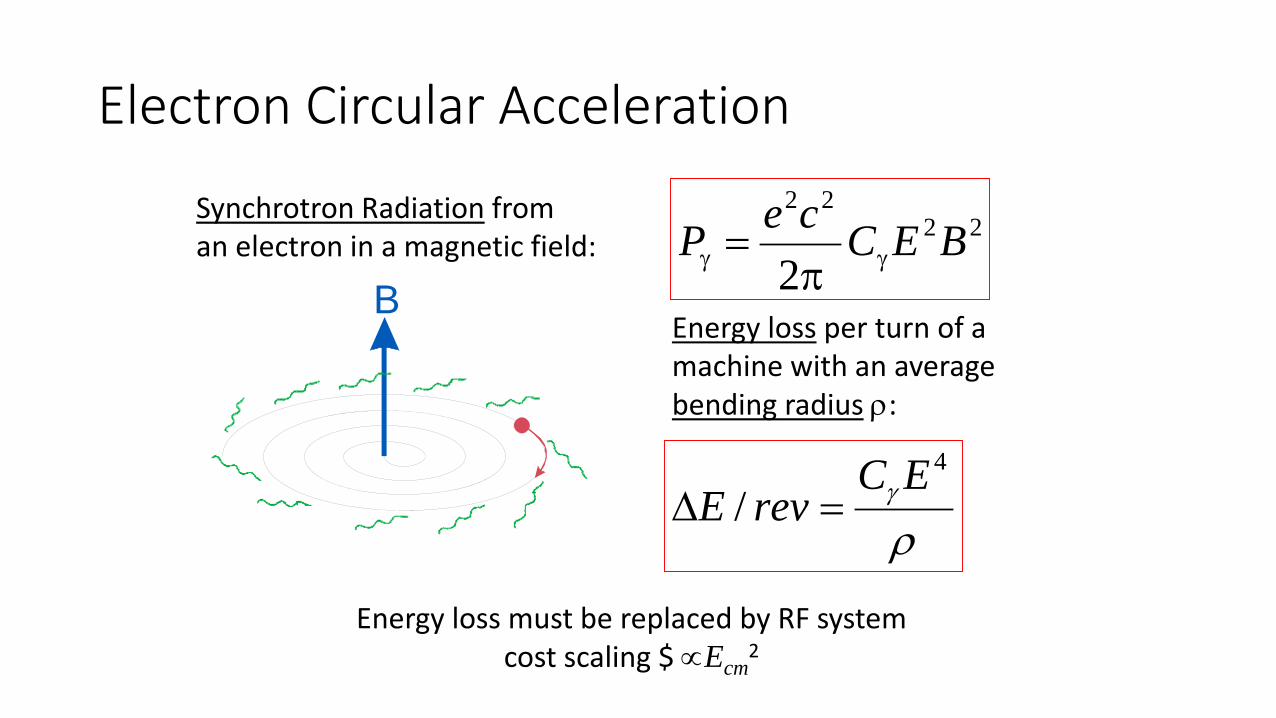
Electron Circular Acceleration
B
Synchrotron Radiation froman electron in a magnetic field:
2222
2BECceP γγ π
=
ργ
4
/EC
revE =∆
Energy loss per turn of a machine with an average bending radius ρ:
Energy loss must be replaced by RF systemcost scaling $ ∝Ecm
2
Running costs
• There is a need for high efficient and reliable power sources when looking at the feasibility of future projects based on large accelerators and the sustainability of high power machines.
• FCC has high power requirements of 100MW CW• This means we need 800 Million kW-hr• At 5p per kW-hr that’s an electricity bill of £40 Million per year
(probably can be negotiated cheaper)• That’s not including losses due to efficiency• FCC will likely have power requirements greater than all of
Manchester.
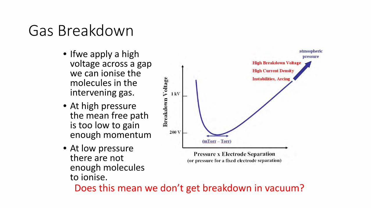
Gas Breakdown• Ifwe apply a high
voltage across a gap we can ionise the molecules in the intervening gas.
• At high pressure the mean free path is too low to gain enough momentum
• At low pressure there are not enough molecules to ionise.Does this mean we don’t get breakdown in vacuum?
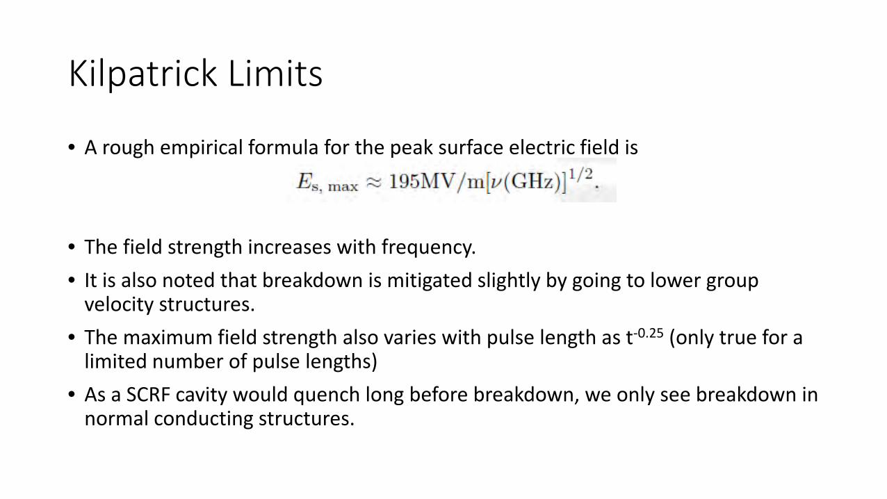
Kilpatrick Limits
• A rough empirical formula for the peak surface electric field is
• The field strength increases with frequency.• It is also noted that breakdown is mitigated slightly by going to lower group
velocity structures.• The maximum field strength also varies with pulse length as t-0.25 (only true for a
limited number of pulse lengths)• As a SCRF cavity would quench long before breakdown, we only see breakdown in
normal conducting structures.
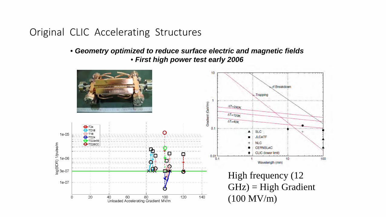
• Geometry optimized to reduce surface electric and magnetic fields• First high power test early 2006
Original CLIC Accelerating Structures
High frequency (12 GHz) = High Gradient (100 MV/m)
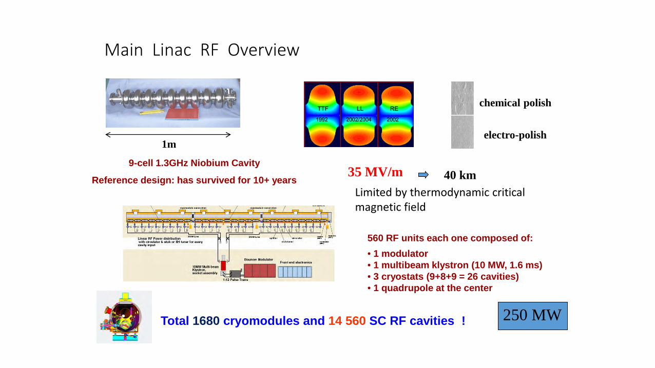
Main Linac RF Overview
560 RF units each one composed of:• 1 modulator• 1 multibeam klystron (10 MW, 1.6 ms)• 3 cryostats (9+8+9 = 26 cavities)• 1 quadrupole at the center
Total 1680 cryomodules and 14 560 SC RF cavities !
1m
9-cell 1.3GHz Niobium Cavity
Reference design: has survived for 10+ years35 MV/m 40 km
chemical polish
electro-polish
250 MW
Limited by thermodynamic critical magnetic field
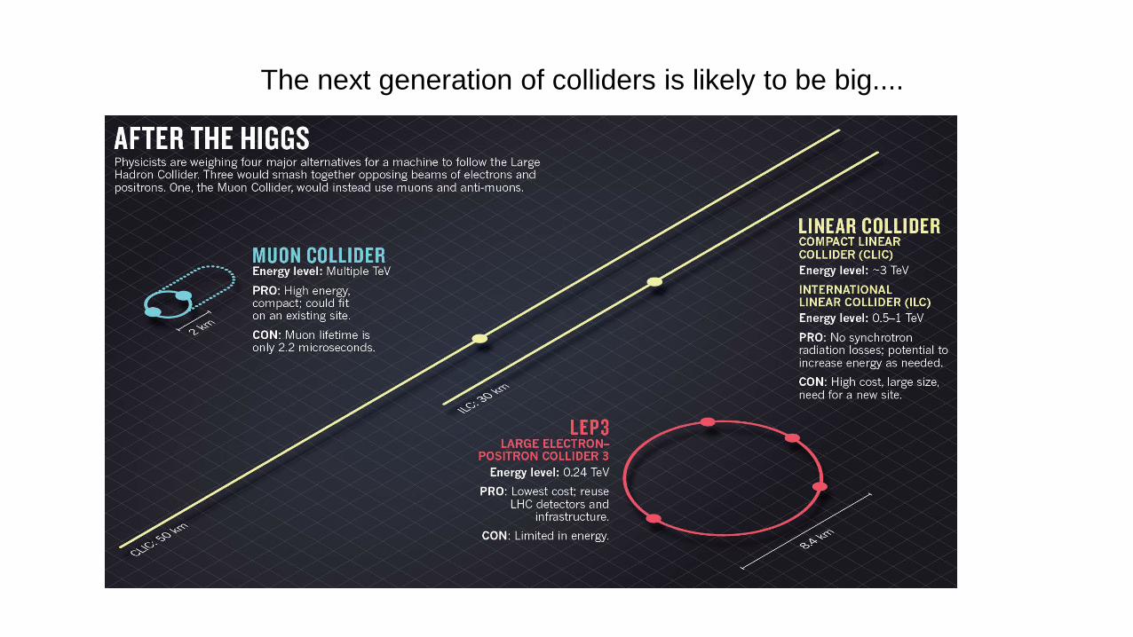
The next generation of colliders is likely to be big....
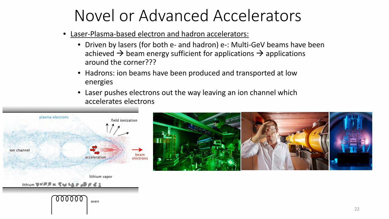
Novel or Advanced Accelerators• Laser-Plasma-based electron and hadron accelerators:
• Driven by lasers (for both e- and hadron) e-: Multi-GeV beams have been achieved beam energy sufficient for applications applications around the corner???
• Hadrons: ion beams have been produced and transported at low energies
• Laser pushes electrons out the way leaving an ion channel which accelerates electrons
22
Laser Plasma Accelerators Challenges• Limited interaction length due to phase slippage between the laser and the beam. This limited energy per
stage.
• Shot-to-shot stability is of the percent level on energy, charge, direction
• Efficiency is at least one or two order of magnitude less than conventional sources (around 1% if that). For a 1 TeV collider at CERN the required power would dwarf the rest of Geneva (roughly 10 times the entire energy budget of Geneva) and would potentially require several new dedicated power stations.
• Rep-rate is limited by material heating to sub-1Hz, this would limit luminosity.
• Laser efficiency and rep-rate could be increased by future laser technology by using optical amplification or locking millions of fibre lasers
• Reaching higher energies requires bigger lasers than are currently available or by staging
• Staging is difficult due to the variation in beam properties and difficulties in injecting both beam and laser23
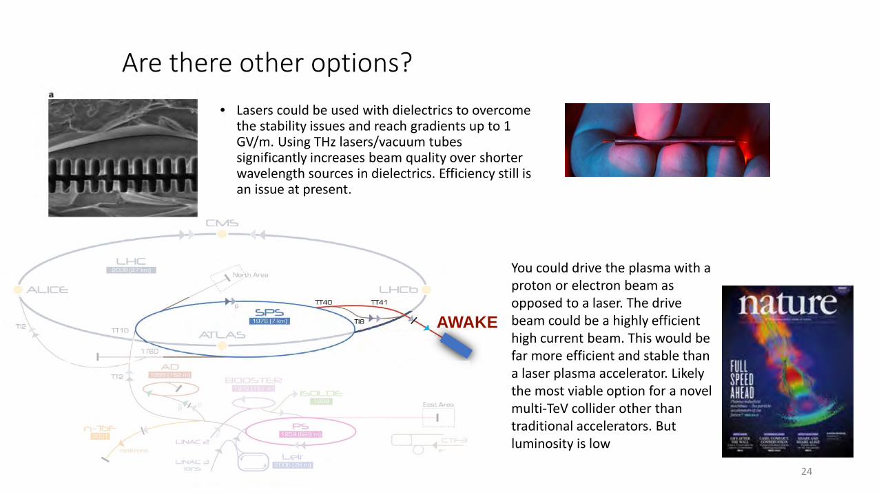
Are there other options?• Lasers could be used with dielectrics to overcome
the stability issues and reach gradients up to 1 GV/m. Using THz lasers/vacuum tubes significantly increases beam quality over shorter wavelength sources in dielectrics. Efficiency still is an issue at present.
24
AWAKE
You could drive the plasma with a proton or electron beam as opposed to a laser. The drive beam could be a highly efficient high current beam. This would be far more efficient and stable than a laser plasma accelerator. Likely the most viable option for a novel multi-TeV collider other than traditional accelerators. But luminosity is low

Brightness frontier
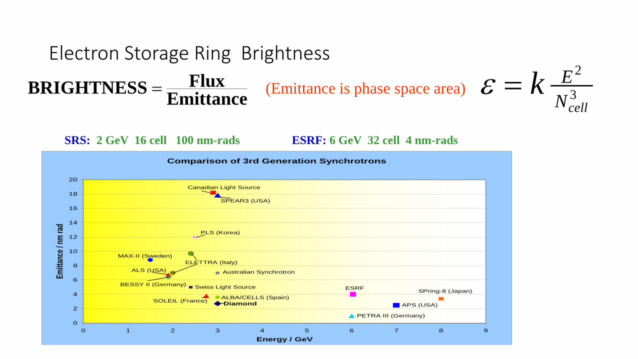
Electron Storage Ring Brightness
EmittanceFluxBRIGHTNESS = 3
2
cellNEk=ε
SRS: 2 GeV 16 cell 100 nm-rads ESRF: 6 GeV 32 cell 4 nm-rads
(Emittance is phase space area)
Comparison of 3rd Generation Synchrotrons
Diamond
Swiss Light Source
APS (USA)
PETRA III (Germany)
ESRF
Canadian Light Source
SPring-8 (Japan)
ELETTRA (Italy)
Australian SynchrotronALS (USA)
SOLEIL (France)
SPEAR3 (USA)
BESSY II (Germany)
MAX-II (Sweden)
ALBA/CELLS (Spain)
PLS (Korea)
0
2
4
6
8
10
12
14
16
18
20
0 1 2 3 4 5 6 7 8 9
Energy / GeV
Emitta
nce /
nm ra
d
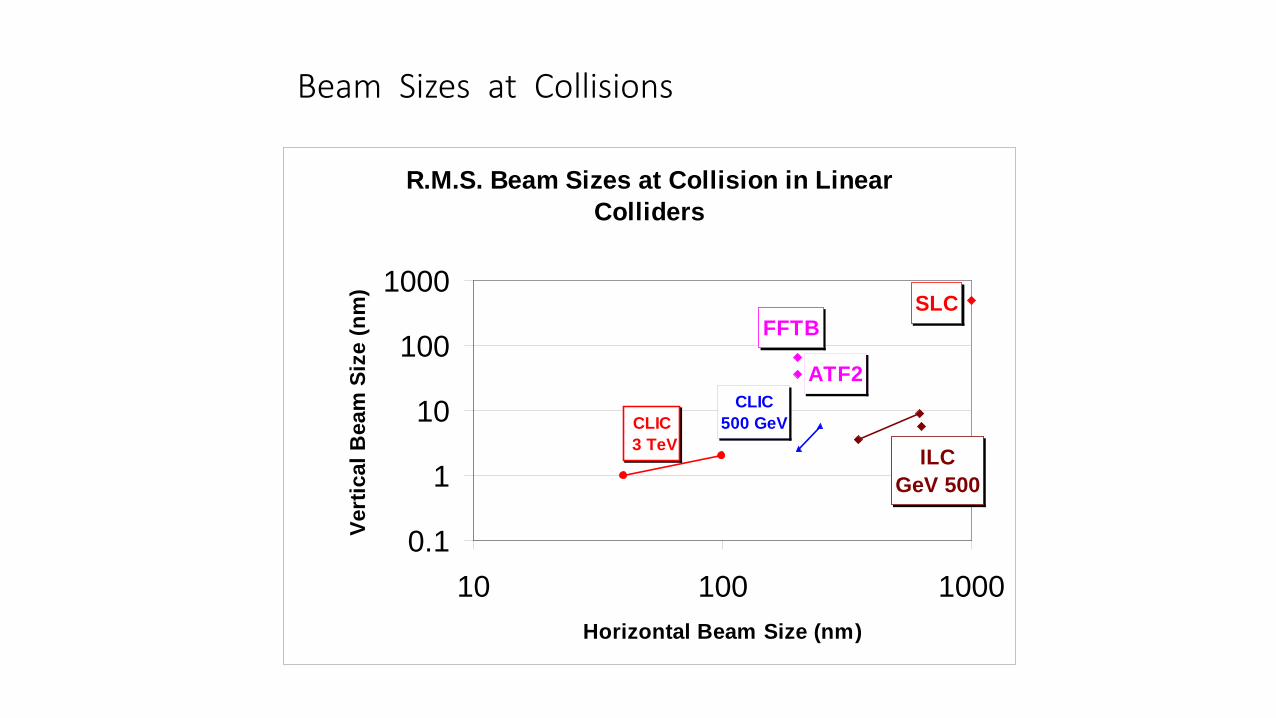
Beam Sizes at Collisions
R.M.S. Beam Sizes at Collision in Linear Colliders
ATF2
SLCFFTB
ILCGeV 500
CLIC500 GeVCLIC
3 TeV
0.1
1
10
100
1000
10 100 1000Horizontal Beam Size (nm)
Vert
ical
Bea
m S
ize
(nm
)
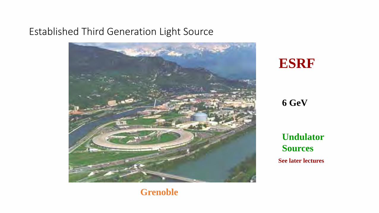
Established Third Generation Light Source
ESRF
Grenoble
6 GeV
UndulatorSources
See later lectures
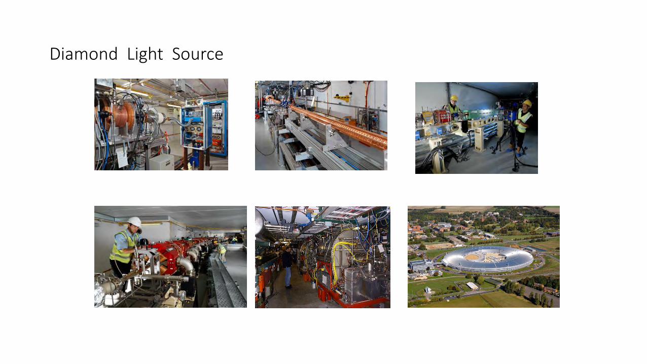
Diamond Light Source
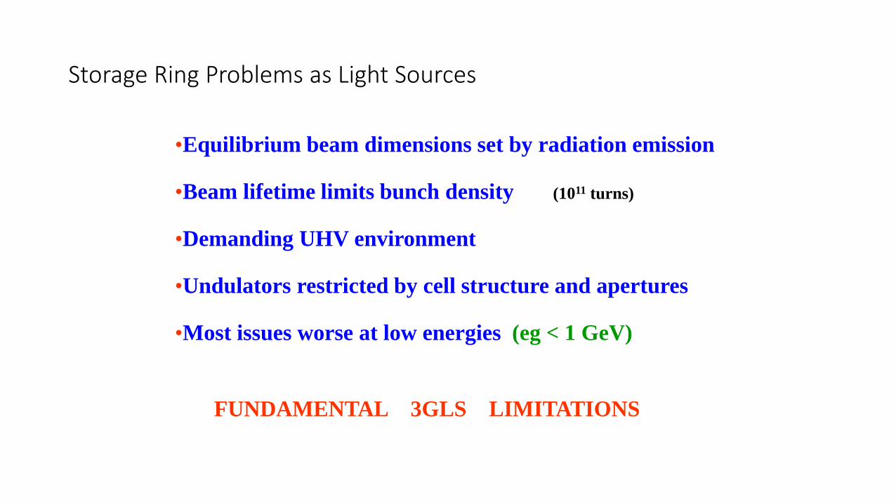
Storage Ring Problems as Light Sources
•Equilibrium beam dimensions set by radiation emission
•Beam lifetime limits bunch density (1011 turns)
•Demanding UHV environment
•Undulators restricted by cell structure and apertures
•Most issues worse at low energies (eg < 1 GeV)
FUNDAMENTAL 3GLS LIMITATIONS
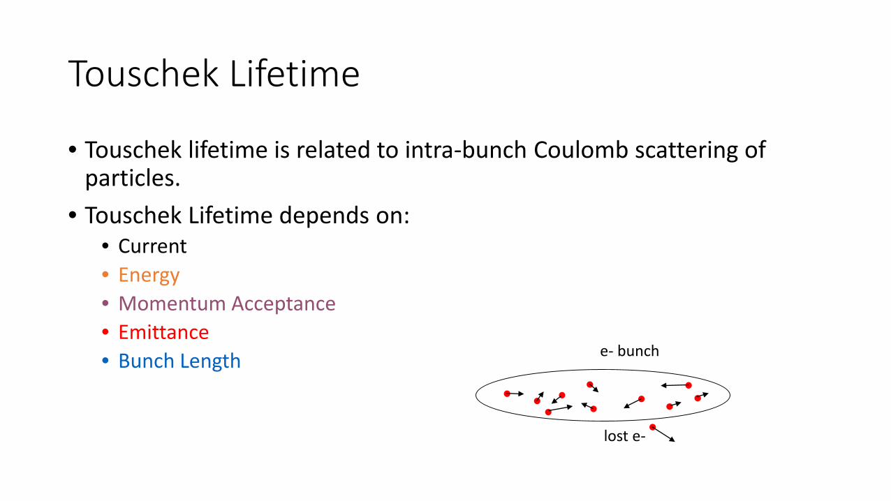
Touschek Lifetime
• Touschek lifetime is related to intra-bunch Coulomb scattering of particles.
• Touschek Lifetime depends on:• Current• Energy• Momentum Acceptance• Emittance• Bunch Length e- bunch
lost e-
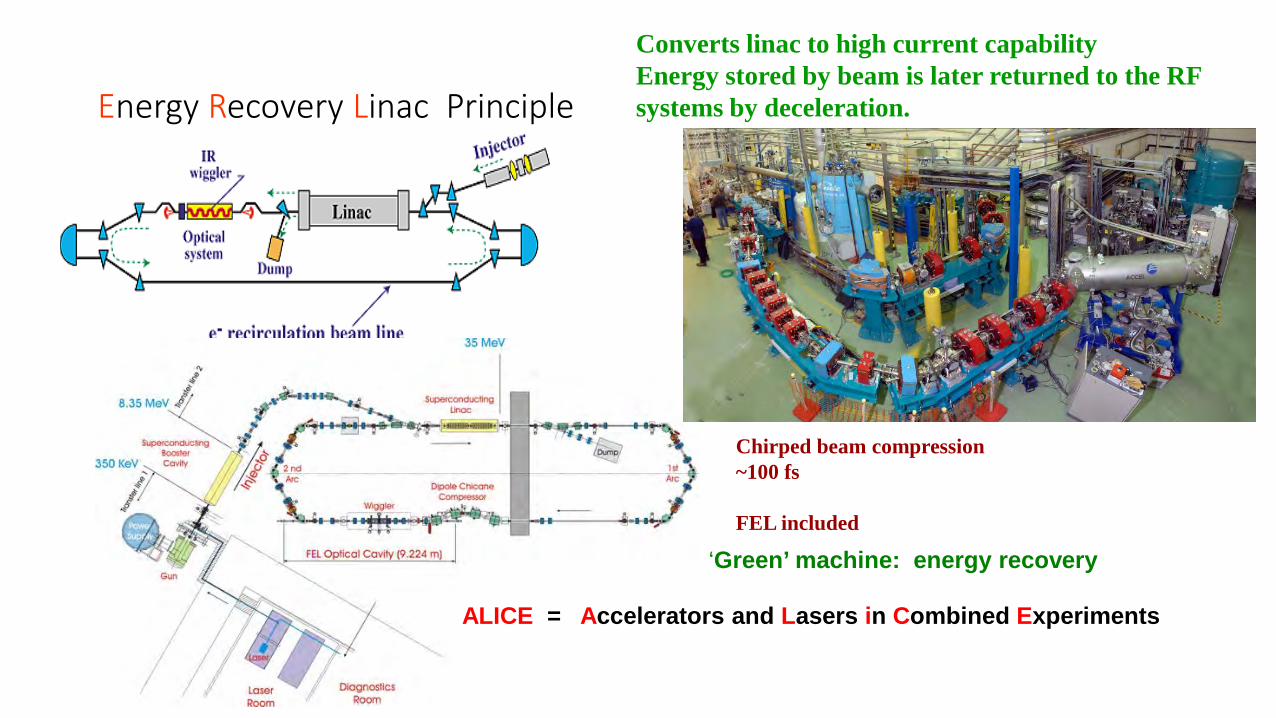
Energy Recovery Linac Principle
Converts linac to high current capabilityEnergy stored by beam is later returned to the RF systems by deceleration.
Chirped beam compression~100 fs
FEL included
‘Green’ machine: energy recovery
ALICE = Accelerators and Lasers in Combined Experiments
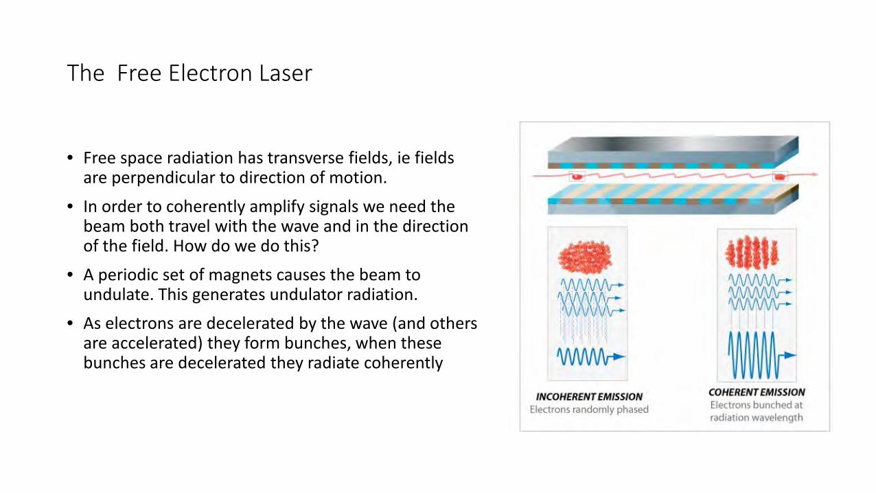
The Free Electron Laser
• Free space radiation has transverse fields, ie fields are perpendicular to direction of motion.
• In order to coherently amplify signals we need the beam both travel with the wave and in the direction of the field. How do we do this?
• A periodic set of magnets causes the beam to undulate. This generates undulator radiation.
• As electrons are decelerated by the wave (and others are accelerated) they form bunches, when these bunches are decelerated they radiate coherently
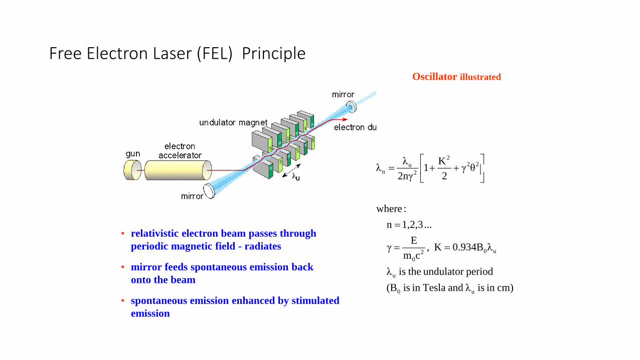
Free Electron Laser (FEL) Principle
cm)in is λ and Teslain is (B periodundulator theis λ
λ0.934BK ,cm
E γ
... 1,2,3n :where
θγ2
K12nγλ λ
u0
u
u020
222
2u
n
==
=
++=
• relativistic electron beam passes through periodic magnetic field - radiates
• mirror feeds spontaneous emission back onto the beam
• spontaneous emission enhanced by stimulated emission
Oscillator illustrated
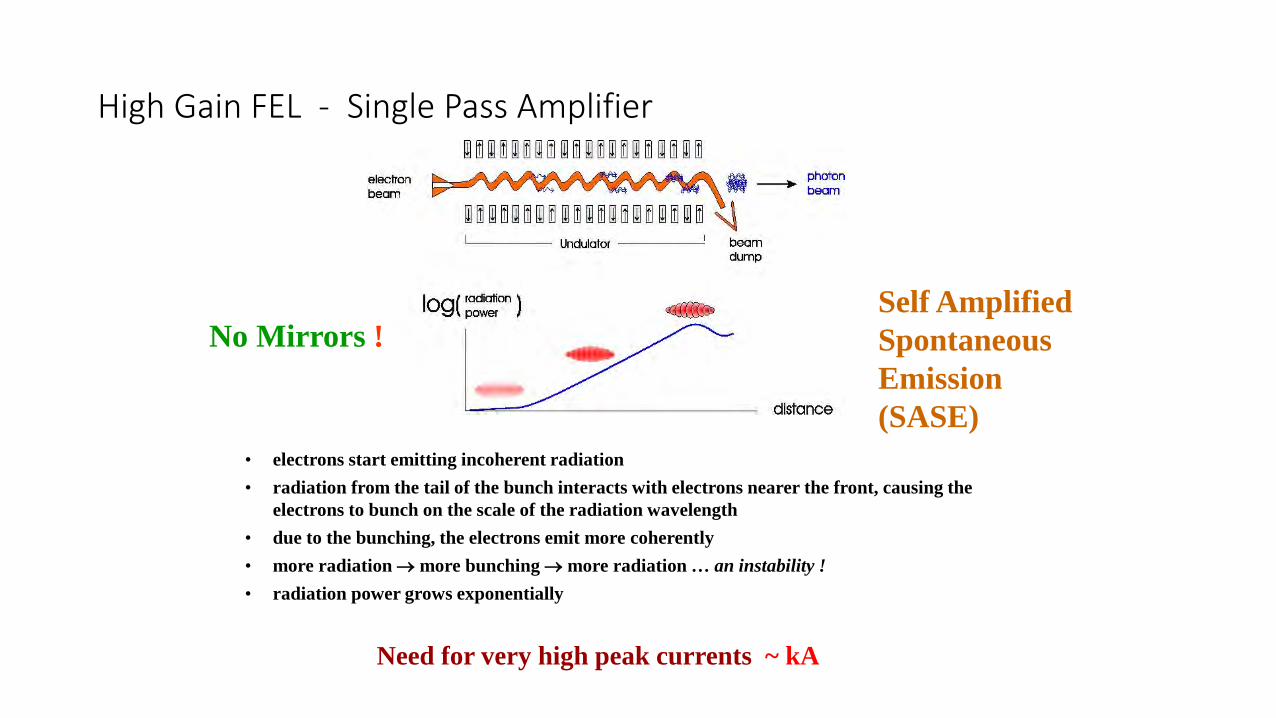
High Gain FEL - Single Pass Amplifier
No Mirrors !
Need for very high peak currents ~ kA
• electrons start emitting incoherent radiation• radiation from the tail of the bunch interacts with electrons nearer the front, causing the
electrons to bunch on the scale of the radiation wavelength• due to the bunching, the electrons emit more coherently• more radiation → more bunching → more radiation … an instability !• radiation power grows exponentially
Self Amplified Spontaneous Emission (SASE)
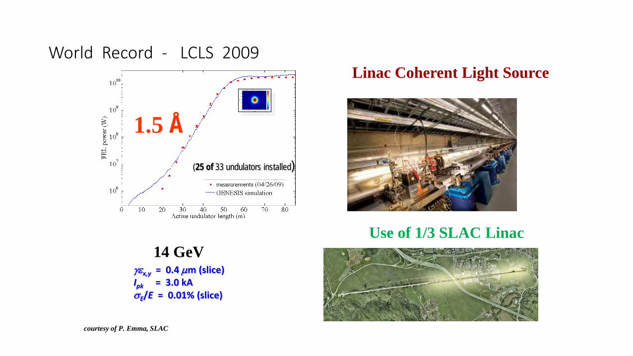
γεx,y = 0.4 µm (slice)Ipk = 3.0 kAσE/E = 0.01% (slice)
(25 of 33 undulators installed)
courtesy of P. Emma, SLAC
1.5 Å
World Record - LCLS 2009
Use of 1/3 SLAC Linac14 GeV
Linac Coherent Light Source
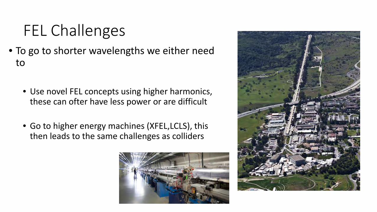
FEL Challenges• To go to shorter wavelengths we either need
to
• Use novel FEL concepts using higher harmonics, these can ofter have less power or are difficult
• Go to higher energy machines (XFEL,LCLS), this then leads to the same challenges as colliders
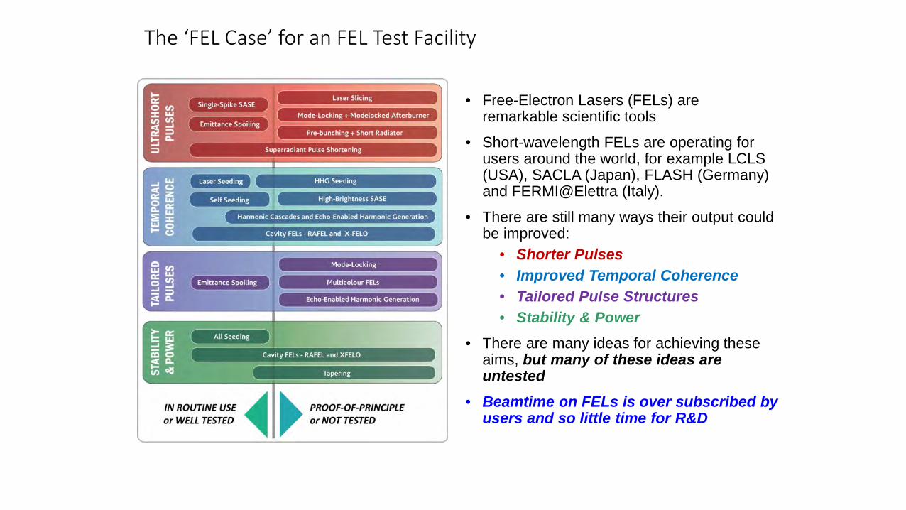
The ‘FEL Case’ for an FEL Test Facility
• Free-Electron Lasers (FELs) are remarkable scientific tools
• Short-wavelength FELs are operating for users around the world, for example LCLS (USA), SACLA (Japan), FLASH (Germany) and FERMI@Elettra (Italy).
• There are still many ways their output could be improved:
• Shorter Pulses• Improved Temporal Coherence• Tailored Pulse Structures• Stability & Power
• There are many ideas for achieving these aims, but many of these ideas are untested
• Beamtime on FELs is over subscribed by users and so little time for R&D
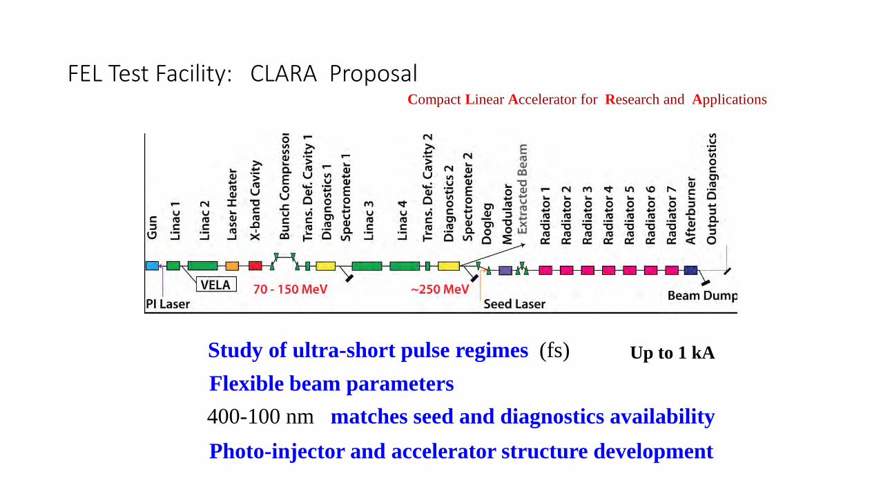
FEL Test Facility: CLARA ProposalCompact Linear Accelerator for Research and Applications
Study of ultra-short pulse regimes (fs)Flexible beam parameters400-100 nm matches seed and diagnostics availabilityPhoto-injector and accelerator structure development
Up to 1 kA
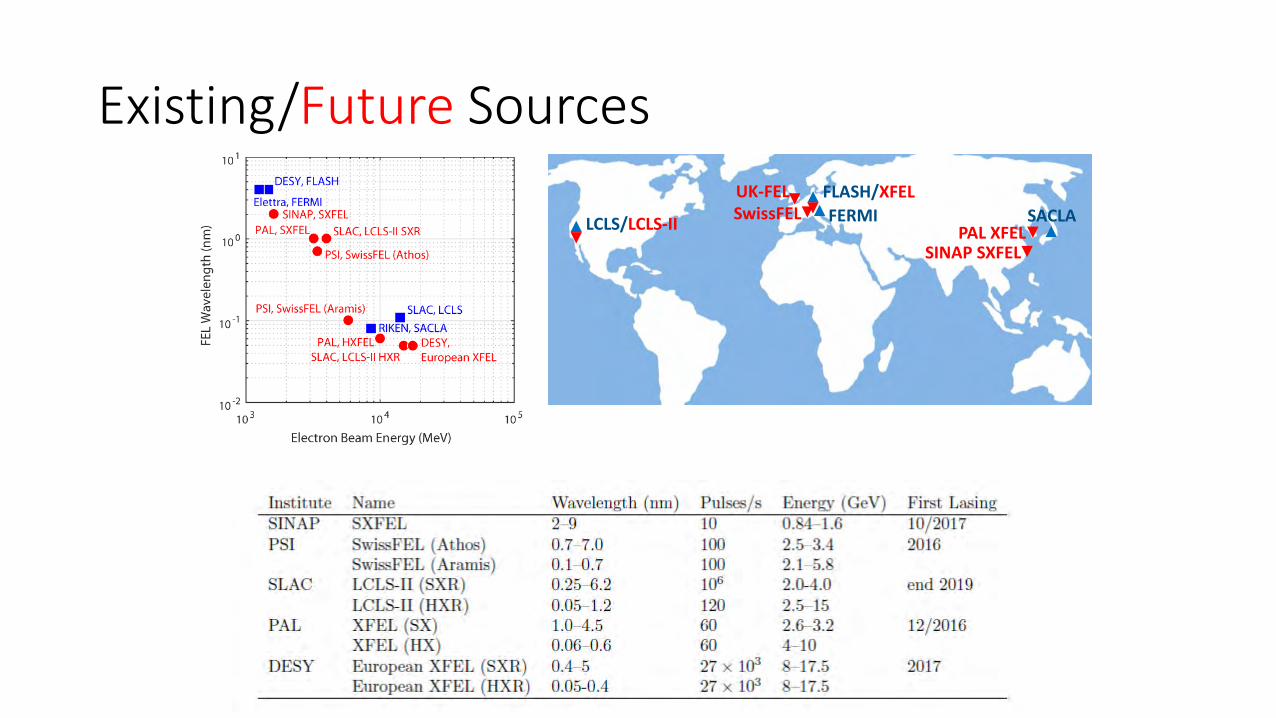
Existing/Future Sources
LCLS/LCLS-II
FLASH/XFELFERMI SACLASwissFEL
PAL XFELSINAP SXFEL
UK-FEL
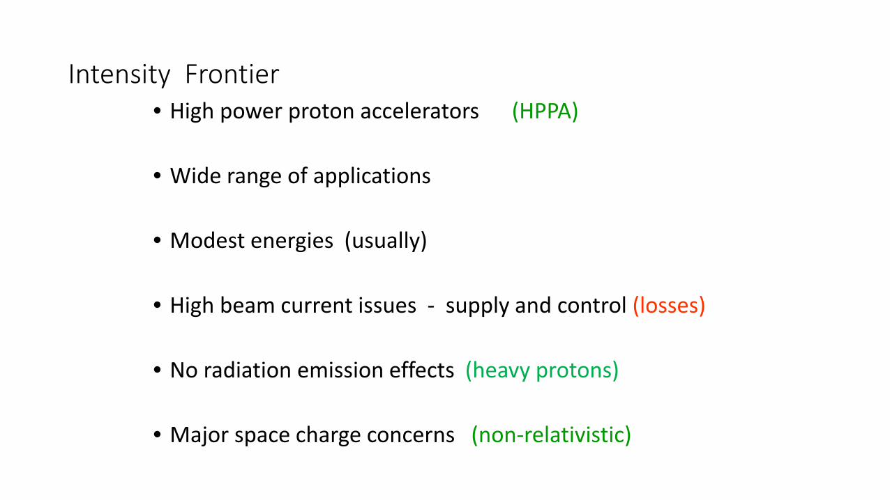
Intensity Frontier• High power proton accelerators (HPPA)
• Wide range of applications
• Modest energies (usually)
• High beam current issues - supply and control (losses)
• No radiation emission effects (heavy protons)
• Major space charge concerns (non-relativistic)
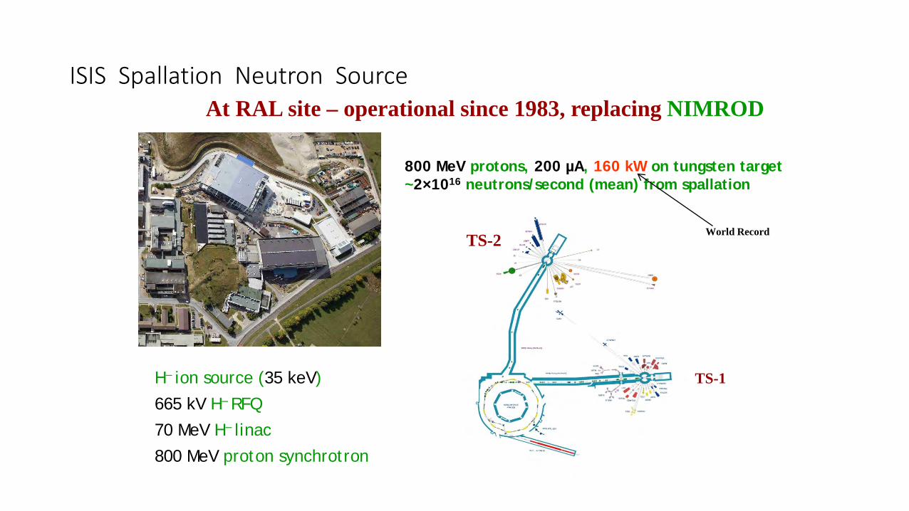
800 MeV protons, 200 µA, 160 kW on tungsten target~2×10¹⁶ neutrons/second (mean) from spallation
ISIS Spallation Neutron SourceAt RAL site – operational since 1983, replacing NIMROD
H– ion source (35 keV)665 kV H– RFQ70 MeV H– linac800 MeV proton synchrotron
TS-2
TS-1
World Record
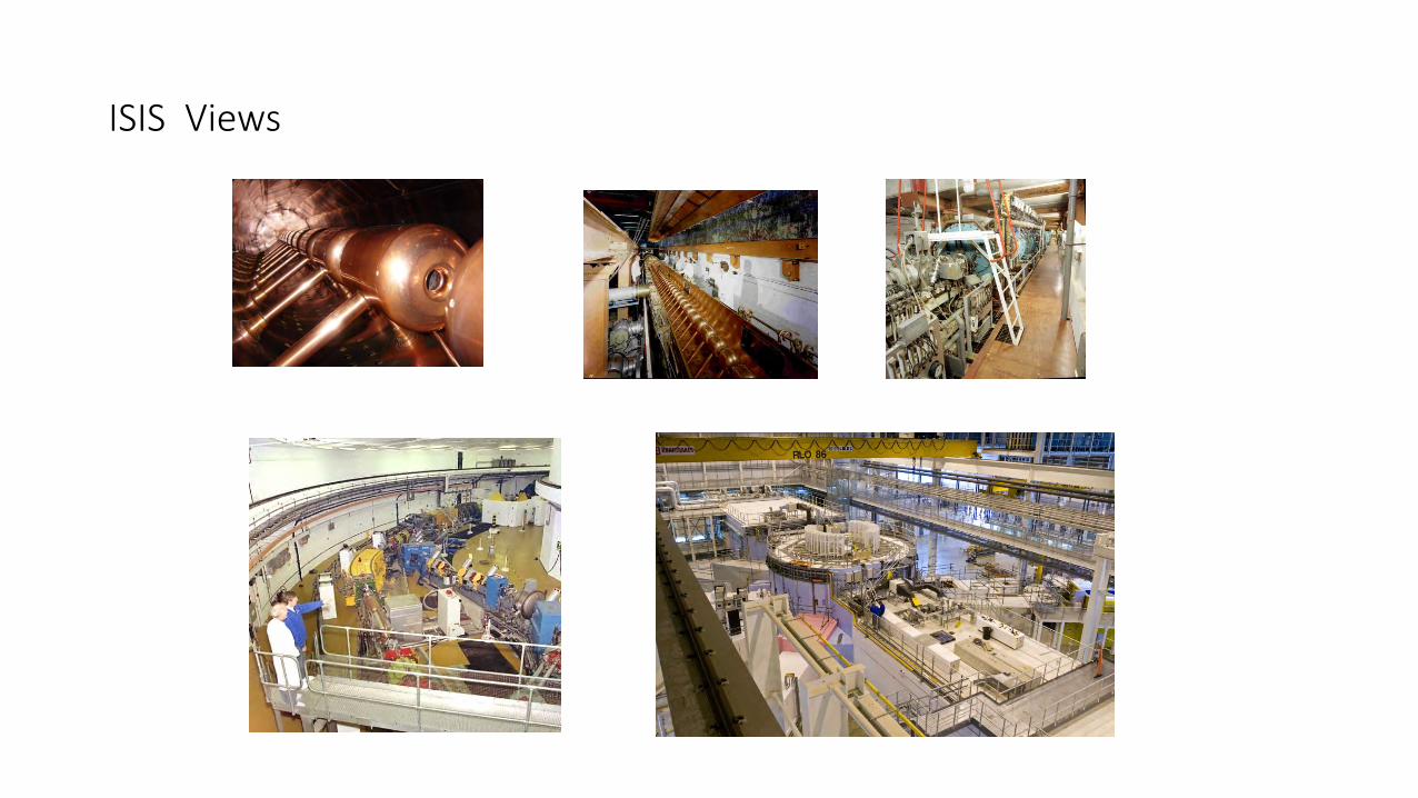
ISIS Views
Intensity Challenges
• Capture and Acceleration at low energy, needs strong focussing (lots of magnets) and different types of accelerating structures matched to the particle velocity.
• High duty cycles (long pulses, and high rep rates) need Superconducting RF to reduce RF losses.
• High power on Targets need liquid metal or high temperatures.• Beam losses (damage and activation)• Space charge (repulsion between protons) blows the beam appart so
strong focussing required
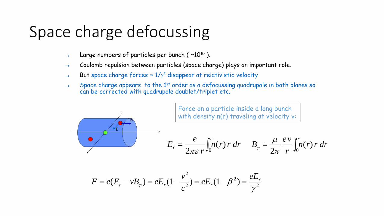
Space charge defocussing→ Large numbers of particles per bunch ( ~1010 ). → Coulomb repulsion between particles (space charge) plays an important role.→ But space charge forces ~ 1/γ2 disappear at relativistic velocity→ Space charge appears to the 1st order as a defocussing quadrupole in both planes so
can be corrected with quadrupole doublet/triplet etc.
∫=r
r drrrnr
eE0
)(2πε ∫=
rdrrrn
rveB
0)(
2πµ
ϕ
Force on a particle inside a long bunch with density n(r) traveling at velocity v:
22
2
2
)1()1()(γ
βϕr
rrreEeE
cveEvBEeF =−=−=−=
E
B
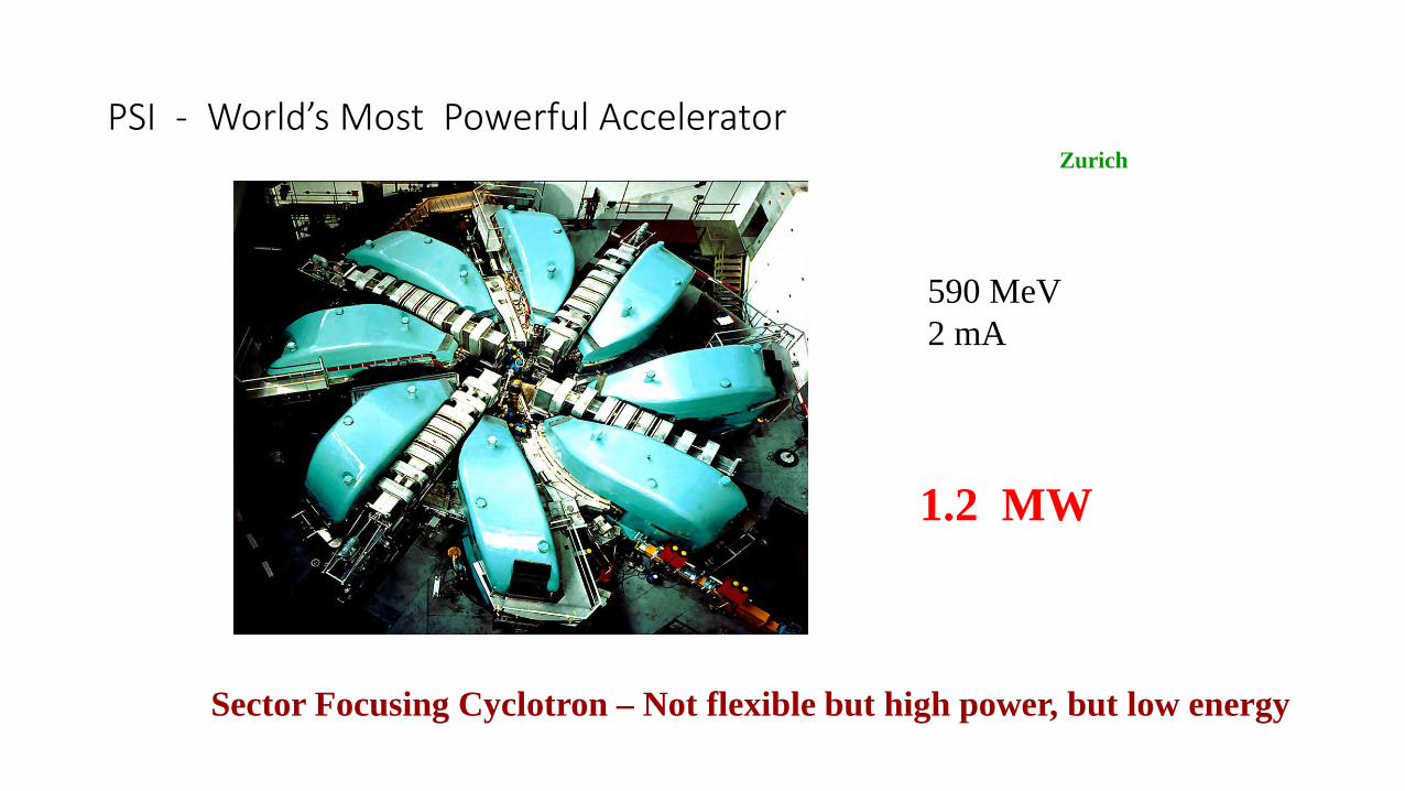
PSI - World’s Most Powerful Accelerator
590 MeV2 mA
1.2 MW
Sector Focusing Cyclotron – Not flexible but high power, but low energy
Zurich
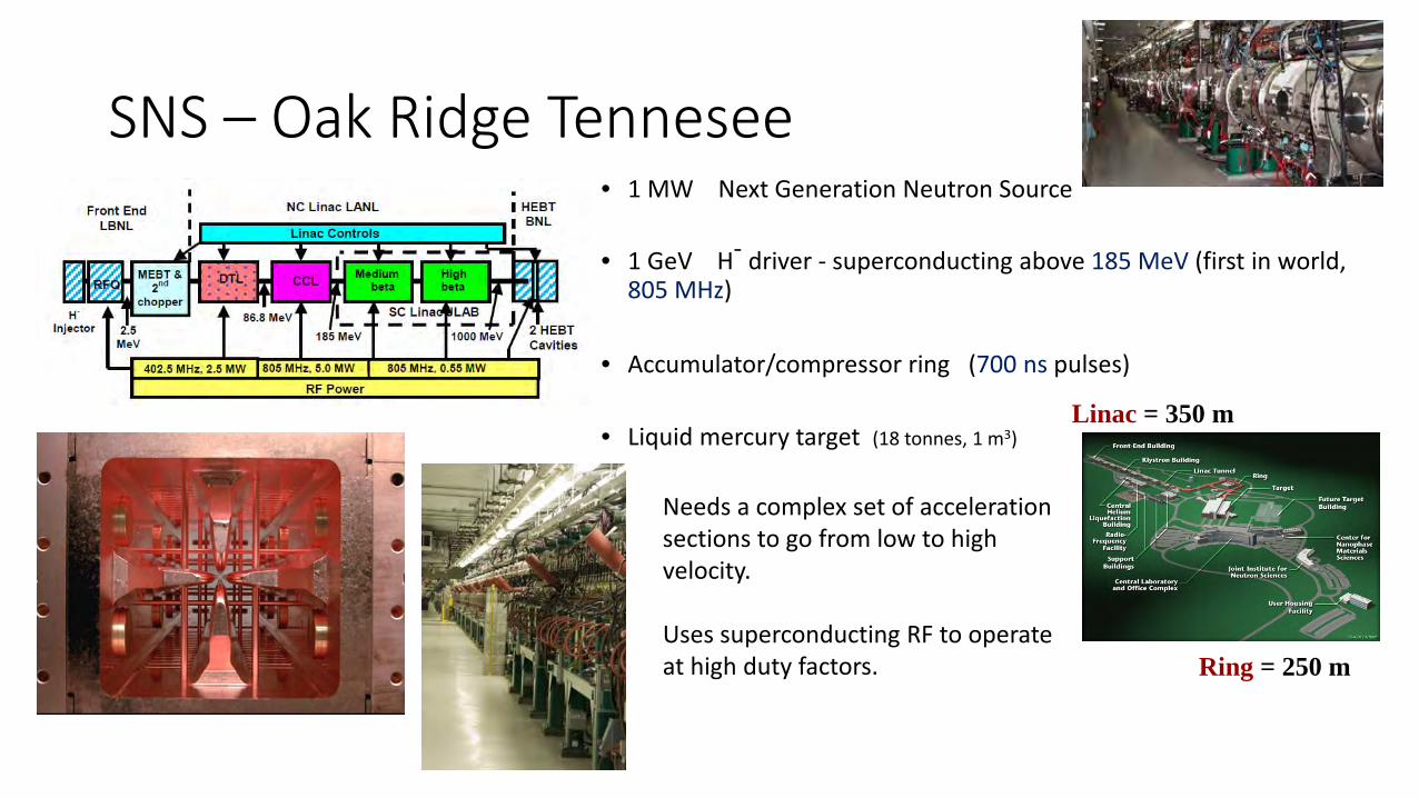
SNS – Oak Ridge Tennesee• 1 MW Next Generation Neutron Source
• 1 GeV H- driver - superconducting above 185 MeV (first in world, 805 MHz)
• Accumulator/compressor ring (700 ns pulses)
• Liquid mercury target (18 tonnes, 1 m3)
Needs a complex set of acceleration sections to go from low to high velocity.
Uses superconducting RF to operate at high duty factors.
Linac = 350 m
Ring = 250 m
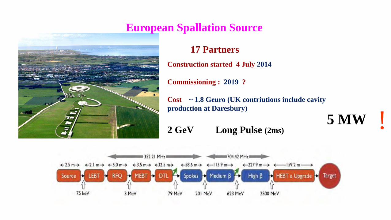
17 PartnersConstruction started 4 July 2014
Commissioning : 2019 ?
Cost ~ 1.8 Geuro (UK contriutions include cavity production at Daresbury)
European Spallation Source
5 MW2 GeV Long Pulse (2ms) !
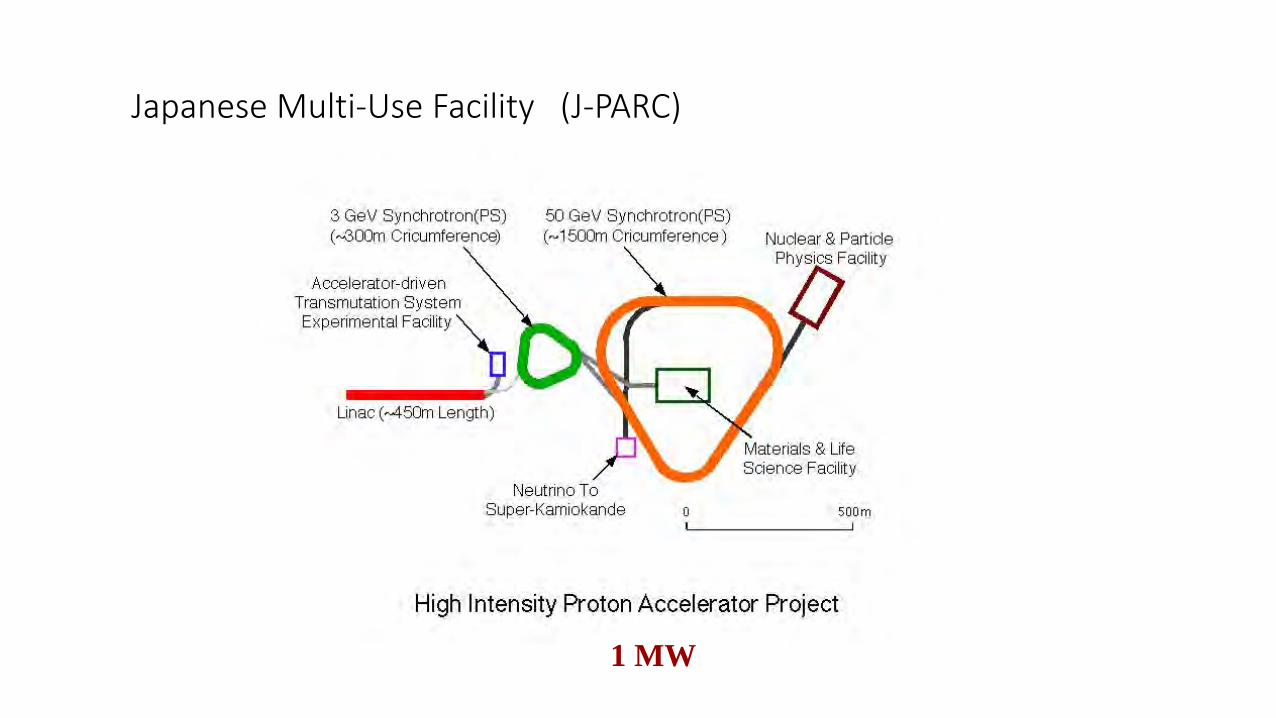
Japanese Multi-Use Facility (J-PARC)
1 MW
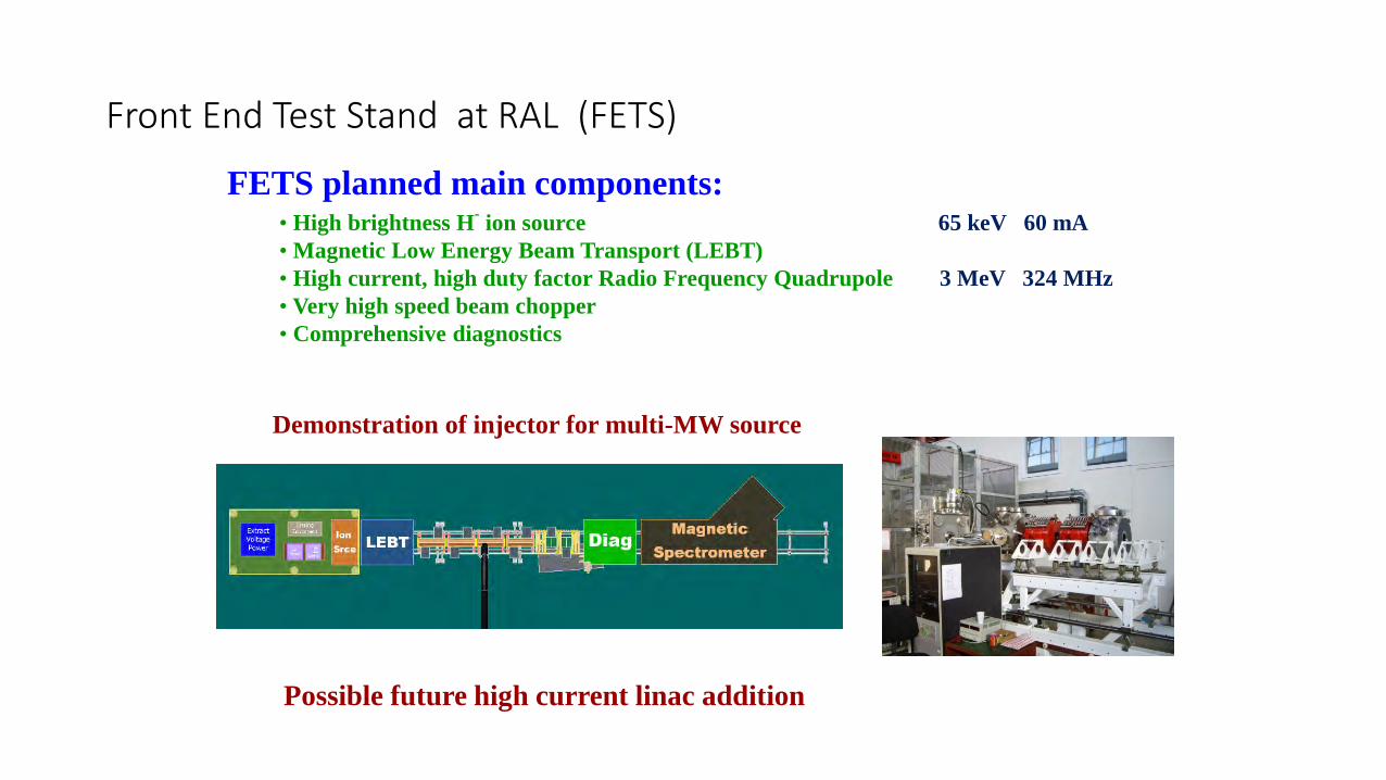
FETS planned main components:• High brightness H- ion source 65 keV 60 mA• Magnetic Low Energy Beam Transport (LEBT)• High current, high duty factor Radio Frequency Quadrupole 3 MeV 324 MHz • Very high speed beam chopper• Comprehensive diagnostics
Front End Test Stand at RAL (FETS)
Demonstration of injector for multi-MW source
Possible future high current linac addition
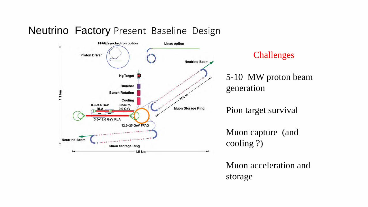
Neutrino Factory Present Baseline Design
Challenges
5-10 MW proton beam generation
Pion target survival
Muon capture (and cooling ?)
Muon acceleration and storage
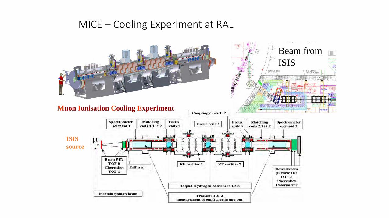
MICE – Cooling Experiment at RAL
Muon Ionisation Cooling Experiment
ISISsource
Beam from ISIS