Embed Size (px)
Citation preview

Introduction to semiconductor
technology

Outline
– 7 Field effect transistors
• MOS transistor ”current equation"
• MOS transistor channel mobility
• Substrate bias effect
• 7 Bipolar transistors
• Introduction
• Minority carrier distribution and terminal currents
• Ebers Moll
• 2nd-order effects

N-Channel MOS-transistor ”current
equation"
The moving charges
in the channel
Both fixed and
moving charge
carriers Differences in work function
and charges in the oxide
Qs=Qn+Qd
Löser ut Qn

N-Channel MOS-transistor ”current
equation"
Neglecting the voltage
dependence of Qd (x)
VT=VFB+2F+Qd(x)/Ci
JFET
Resistivity
(cm)
Z
2h
dx
dV
ID R
U
R
dVI x
D
N-Channel MOS-transistor ”current
equation"
For the MOS channel applies:
dx
dVZxQEZxQxvZxQI x
nnnnnd )()()()(
N-Channel MOS-transistor ”current
equation"
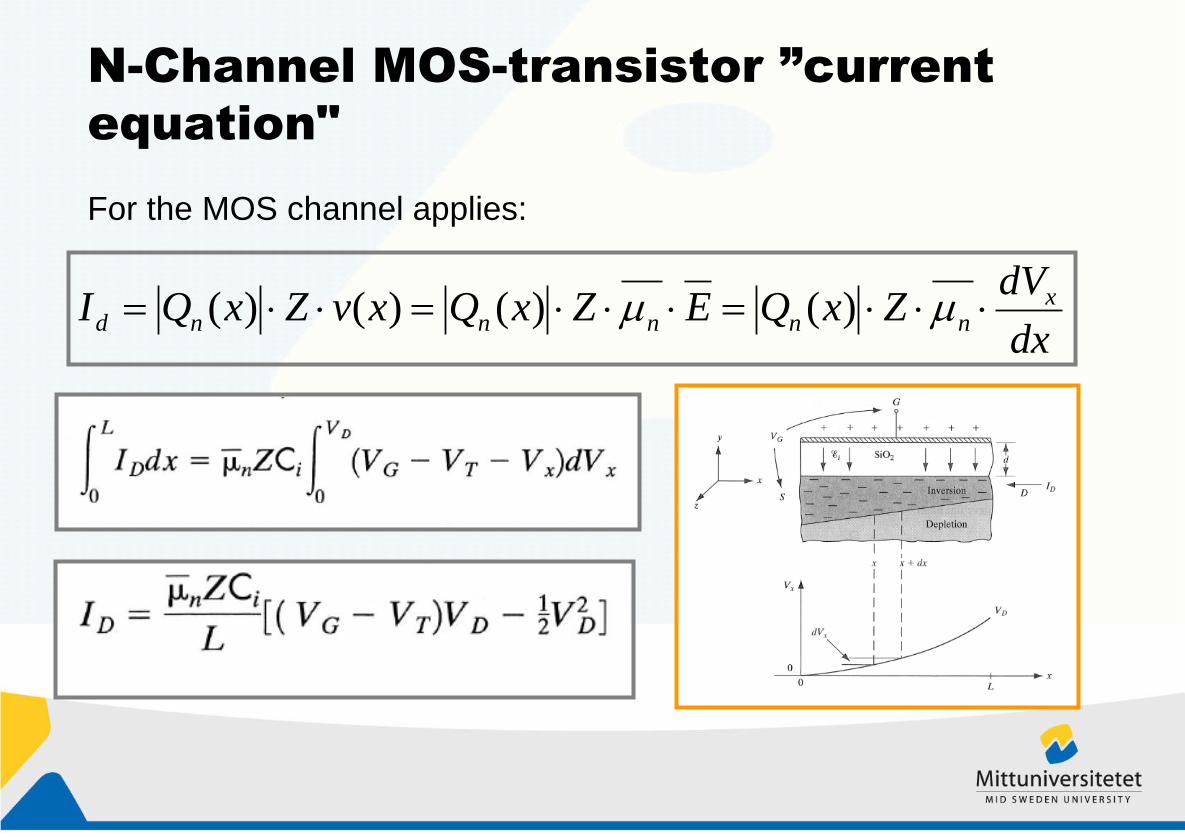
”pust”
The conductivity in the linear part can be described by
VD<<VG-VT

N-Channel MOS-transistor ”current
equation"
In the saturated region applies:

N-Channel MOS-transistor ”current
equation"
Transconductance in saturerad region:

MOS transistor channel mobility
The effective electric field
according to the enclosed
charging according to the
"gauss theorem"
Electron
hole

MOS transistor channel mobility
Mobility degrading factor

MOS transistor channel mobility

Substrate bias effect
The substrate has previously been connected to the source terminal. In some cases, a potential arise between the source and the substrate. One example is the integrated circuits in which the source electrode must be kept insulated from the substrate. A number of transistors can then be attached optionally, without interfering. Note the substrate must be reverse biased relative to the source and drain

Substrate bias effect
If VB>>2F (0.6V)
MOS capacitance at
strong inversion

Bipolar transistor, introduction
a) A diode with lighting controllable diode!
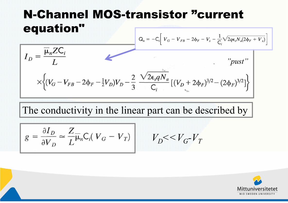
Bipolar transistor, introduction (pnp)
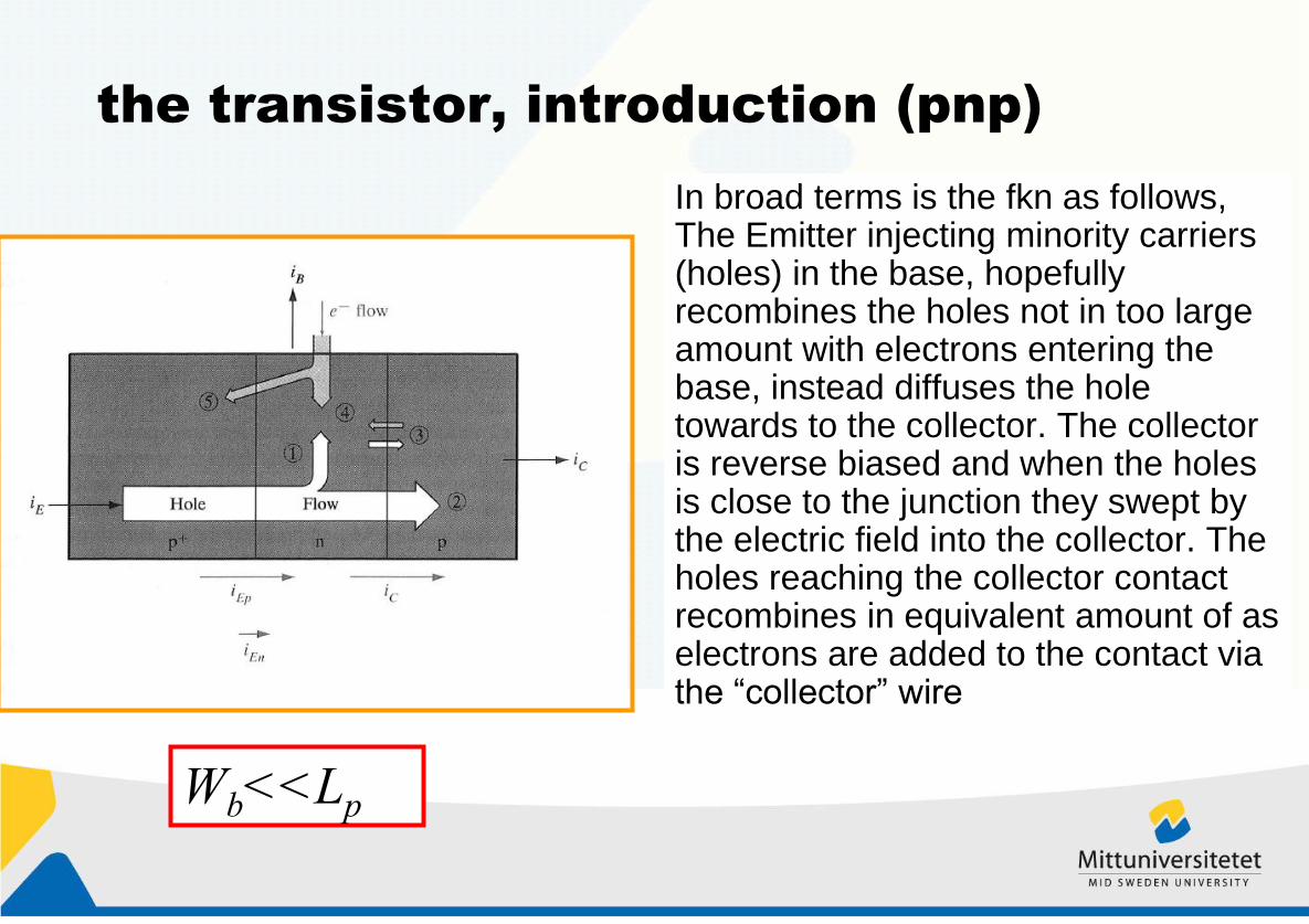
the transistor, introduction (pnp)
In broad terms is the fkn as follows, The Emitter injecting minority carriers (holes) in the base, hopefully recombines the holes not in too large amount with electrons entering the base, instead diffuses the hole towards to the collector. The collector is reverse biased and when the holes is close to the junction they swept by the electric field into the collector. The holes reaching the collector contact recombines in equivalent amount of as electrons are added to the contact via the “collector” wire
Wb<<Lp

the transistor, introduction, terminal
currents and parameters
Base transport factor
Emitter injection efficiency
Hole current
Current transfer
ratio
Current amplification
factor

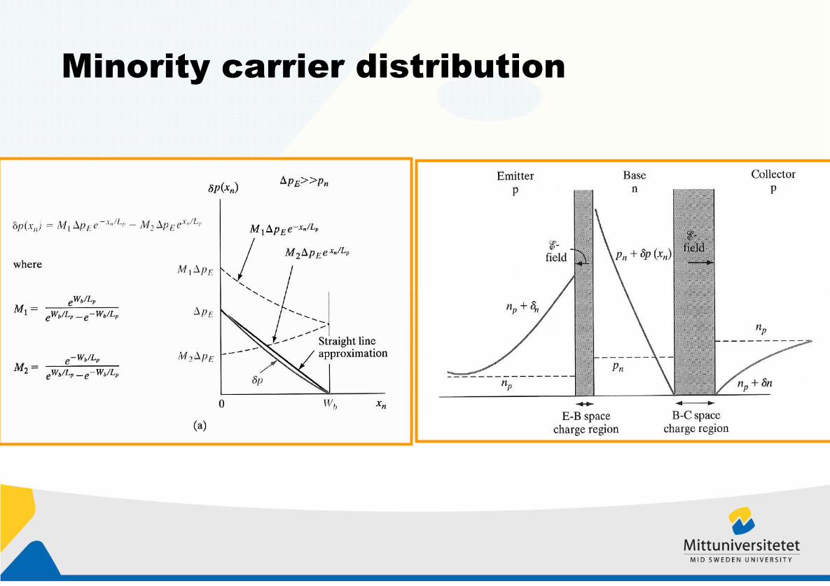
Minority carrier distribution and
terminal currents (pnp)
Some simplifications and assumptions:
• Holes diffuse from emitter to collector "no drift in base“
• Emitter current consists only of hole current
• No saturation in the collector current
• A dimensional analysis
• Currents and voltages are in the "steady state"-no change

Minority carrier distribution (pnp)
Emitter diode is forward
biased and the collector-diode
is reversed biased, which
results in:

Minority carrier distribution (pnp)
Possible to solve the distribution of
hole concentration in the base (see 4-34b)
The solution for hole in
the base region
Constraints

Minority carrier distribution
The solution gives C1 and C2
Hole distribution in the base
Minority carrier distribution

Terminal currents
From EQ. 4-22b, hole
current in the base
Emitter current
Collector current
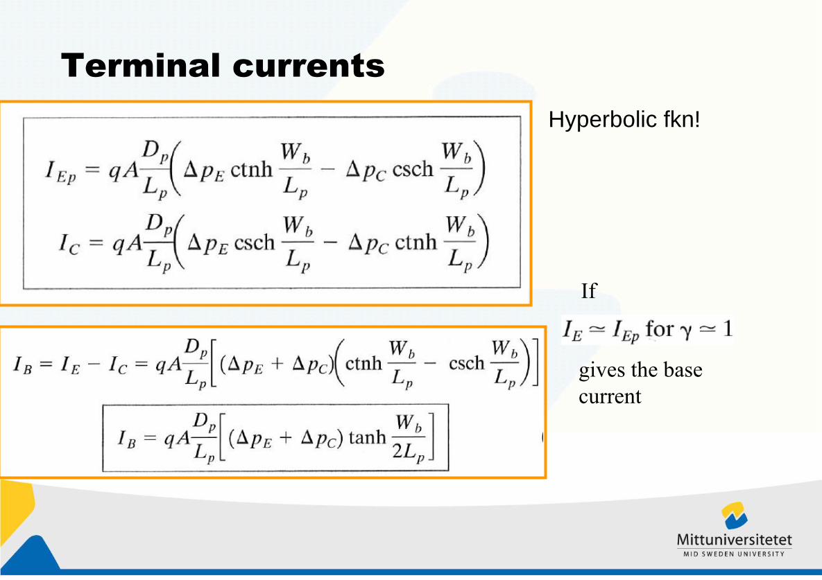
Terminal currents
Hyperbolic fkn!
gives the base
current
If

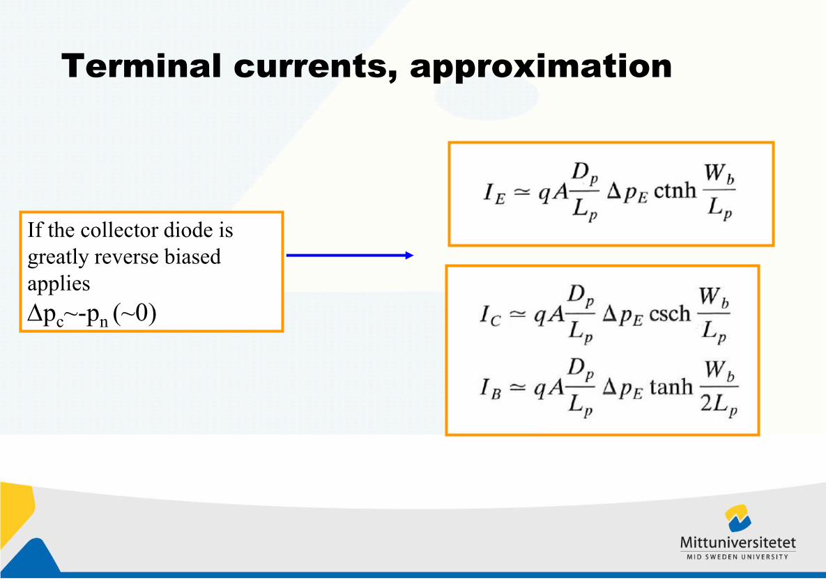
Terminal currents, approximation
If the collector diode is
greatly reverse biased
applies
pc~-pn (~0)
Terminal currents, approximation
If the collector diode is
greatly reverse biased
applies
pc~-pn (~0)

Terminal currents, approximation
Wb/Lp<<1
Use two terms from the
serie
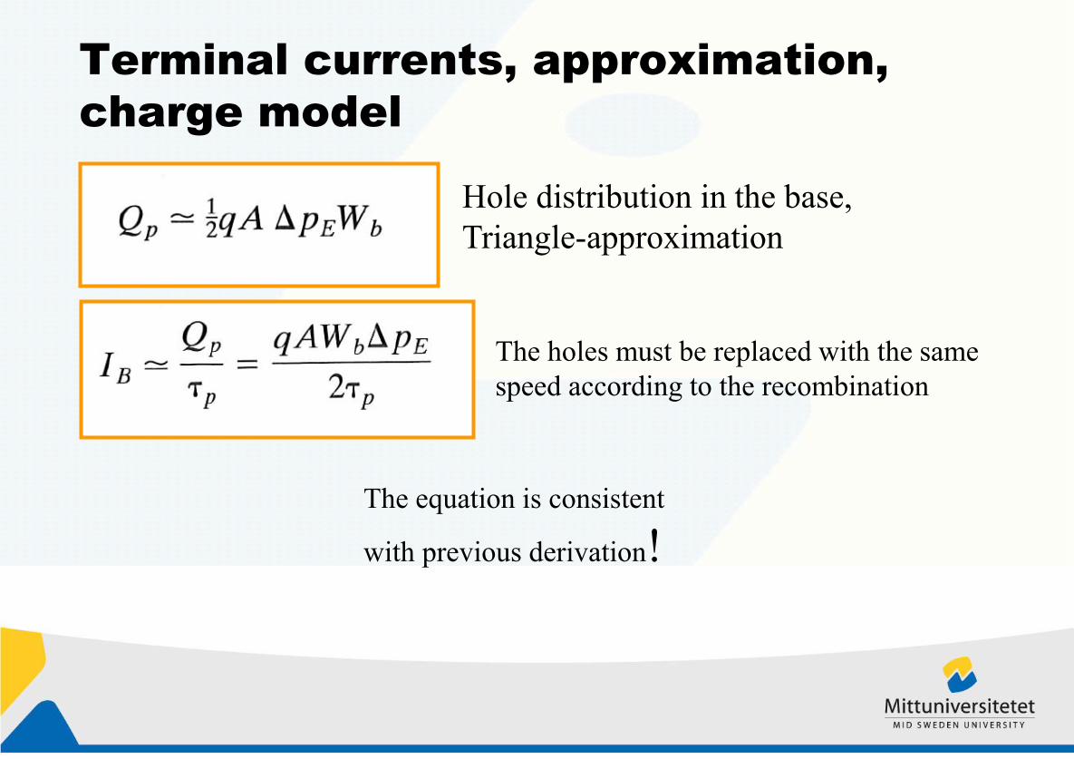
Terminal currents, approximation,
charge model
Hole distribution in the base,
Triangle-approximation
The holes must be replaced with the same
speed according to the recombination
The equation is consistent
with previous derivation!

Emitter-injection factor, base-
transport factor
Emitter current consists of holes-injection
and electron-injection charges only if=1
For <1 ;

Ebers-Moll Equations coupled diode
model, overview

2nd-order effects, doping profile base
The base is not homogeneously doped but instead has a
decreasing doping profile! The doping profile creates an electric
field
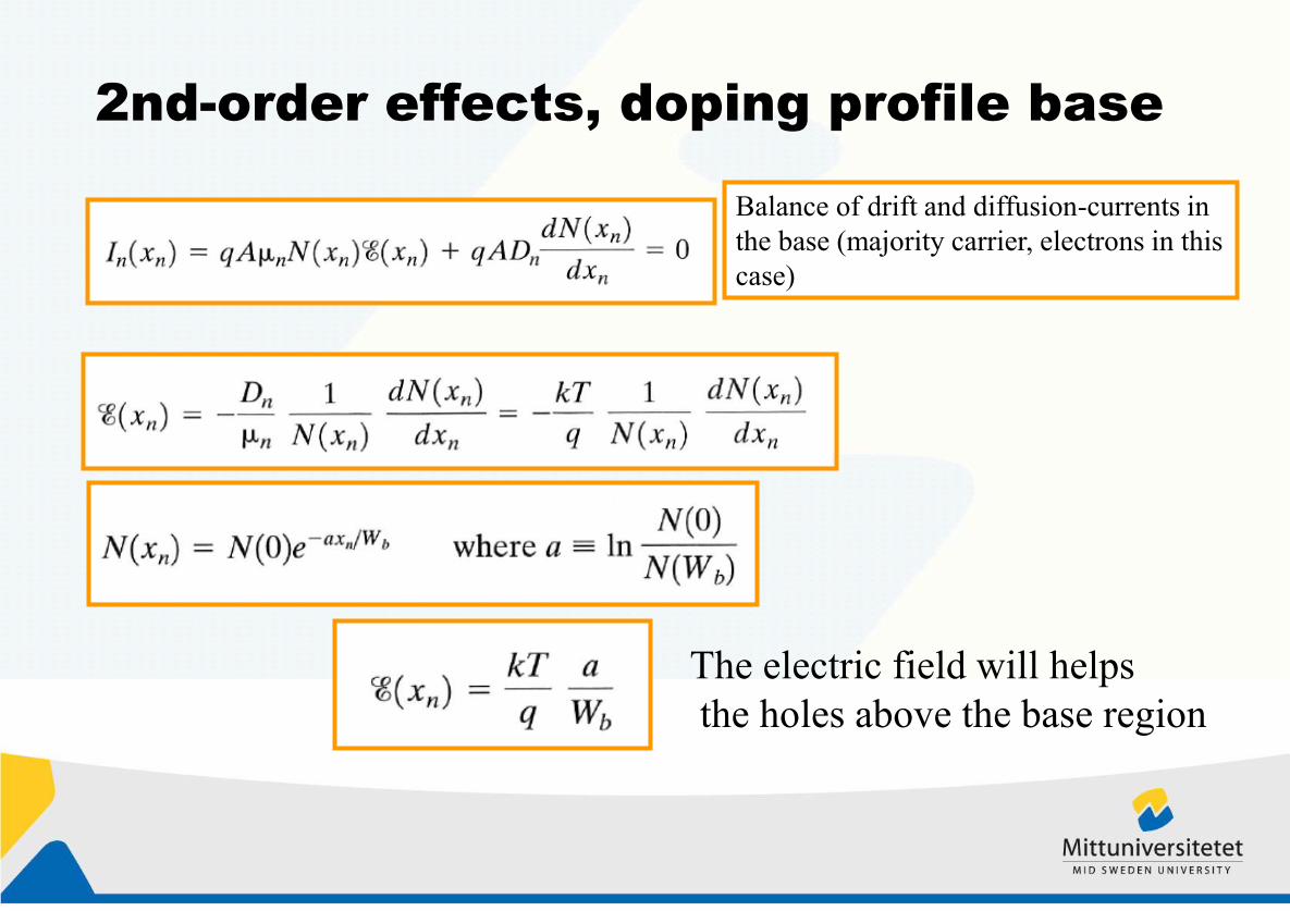
2nd-order effects, doping profile base
Balance of drift and diffusion-currents in
the base (majority carrier, electrons in this
case)
The electric field will helps
the holes above the base region
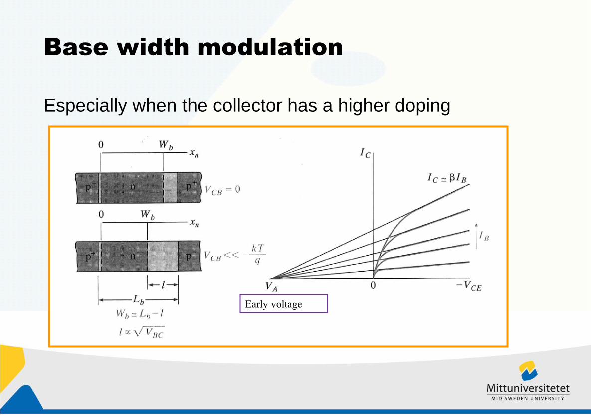
Base width modulation
Especially when the collector has a higher doping
Early voltage

Avalanche breakthrough in collector
base diode

current gain factor decreases with
higher currents
•Pga
•High injection in emitter-diode
•Minority carrier concentration is
approaching the majority carrier
concentration, n = 2 in the diode
equation and current does not
increase as fast
•Kirk effect
–Free charge carrier (as hole) as
they injected in the base collector
diode, increases the concentration
on the n-side and reduces the
concentration on the p-side. As a
result, the transition moves
instantaneously, as well as the
base transport time increases
Free
injected
holes