Embed Size (px)
Citation preview

INVESTIGATING THE EFFECT OF THE ORTHOTROPICPROPERTY OF PIEZOELECTRIC PVDF
S. Sokhanvar, A. Zabihollah, R Sedaghati
Department ofMechanical and Industrial EngineeringConcordia University
1455 de Maisonneuve Blvd. WestMontreal, Quebec H3G IM8, CANADA
[email protected], [email protected]
Received August 2006, Accepted March 2007No. 06-CSME-40, E.I.C. Accession 2959
ABSTRACTThe applications of the piezoelectric PolyvinylideneFluoride, PVDF, integrated with the bearns, plates, and
membranes, performing as sensor, actuator or combination have been received considerable attention in the recentyears. However, not much work has been reported on the influence of the PVDF's orthotropic behavior, particularlythe effect of the orientation of the PVDF fihn in the host structure, on the performance of the system. In the presentstudy, the effect of the piezoelectric PVDF fihn orientation on the output voltage, the actuation force, and thedynamic response ofthe integrated structures has been studied using the finite element method. In the sensory mode,the difference between the output voltages obtained from the biaxial piezoelectric PVDF fihn and uniaxial one,when the orientation of the fihn varies from 0 to 90 degree, is investigated. In each case the proportion contnbutions
. of the involved piezoelectric coefficients including d31 , dn and d33 are studied. Alternatively, in the actuation
mode, the effect of orthotropic behavior of the actuator on the nodal displacements has been taken intoconsideration. The influence ofthe material orthotropic property ofthe transducer onthe free undamped response ofthe system is also investigated. Moreover an effective Young's modulus and effective Poisson ratio for the uniaxialPVDF fihn has been introduced using an optimization procedure to minimize the error caused by isotropicassumption ofuniaxial PVDF fihn.
RECHERCHE SUR L'EFFET DE LA PROPRIETE ORTHOTROPEDU PVDF PIEZOELECTRIQUE
RESUMEAu cours des demieres annees, une attention toute particuliere a ete portee a l'application de polyfluorure devinylidene piezoelectrique (PVDF) integrl! aux poutres, plaques et membranes et agissant comme capteur, actuateurou connexion. Cependant, it y a .tres peu de travaux de recherche qui ont ete presentes sur l'infIuence ducomportement orthotrope du PVDF sur la performance du systeme, et plus particulierement sur l'effet del'orientation de la pellicule de PVDF dans la structure. La presente etude, qui a ete realisee al'aide de la methodedes elements fmis, porte sur l'effet de I'orientation de la pellicule de PVDF piezoelectrique sur la tension de sortie,la force motrice et la reponse dynamique des structures integrees. En mode sensoriel, une etude a ete faite sur ladifference entre les tensions de sortie obtenues apartir d'une pellicule de PVDF piezoelectrique biaxe et uniaxelorsque que I'orientation de la pellicule varie entre 0 et 90 degre. Dans chaque cas, les contributionsproportionnelles des coefficients piezoelectriques impliques, incluant d31, d32 et d33, ont egalement ete etudiees.En mode action, I'effet du comportement orthotrope de I'actuateur sur les deplacements nodaux a ere pris enconsideration. L'influence de la propriete orthotrope du mareriau du transducteur sur la reponse non amortie dusysteme a aussi ete examinee. De plus, un module de Young et un coefficient de Poisson effectifs pour la pelliculede PVDF uuiaxe ont ete introduits en utilisant une methode d'optimisation afin de minimiser les erreurs causees parI'hypothese d'une pellicule de PVDF uuiaxe isotrope.· .
Tra1l1laclions ofthe CSME Ide la SCGM Vol. 31, No. 1,2007 III

--------------------_.--- -_...•_-
1. INTRODUCTION
._---
Since 1970's, when the enhanced piezoelectricity of PolyVinyHdene DiFluoride, PVDF, wasachieved [1], due to its combined merits of high elasticity, high processing capacity, and highpiezoelectricity, the investigation on its properties and applications has been increasingly grown.
The successful applications ofPVDF in beams, plates, and membranes for the vibrationcontrol [2, 3], damage detection or structure health monitoring [4, 5], shape and motion control[6], force and pulse sensing applications [7], among many others are increasingly reported in theliterature. However, the orthotropic properties of PVDF and their influence on the performanceofthe constructed systems are often overlooked. The discrepancy observed between few reportedvalues for the material properties of the ·orthotropic PVDF, which has root in dissimilarmechanical and electrical production process, is one of the obstacles in considering theanisotropic properties of the piezoelectric PVDF in the studies. Various electrical andmechanical properties for the uniaxial and biaxial PVDF film are reported by differentmanufacturers are given in Table 1 [8-10].
Table 1. PVDF properties reported by manufacturers. Piezoelectric and Elastic coefficients aregiven in pC/ N and GPa respectively. The d'h' represents the hydrostatic piezoelectric
coefficient.Uniaxial PVDF Biaxial PVDF
d31 d'2 d" d3l• En E22 E" d,! =d'2 d" En =E22
Piezoflex 14 2 -34 -18 2.5 2.1 0.9 - - -Goodfellow 18-20 2 -20 -6 1.8-2.7 1.7-2.7 - 8 15-16 2Piezotech 18 3 -20 - - - - 7 -24 -
Discrepancy between the reported piezoelectric properties is evident from Table 1. Furthermore,the material properties of PVDF have been measured using different techniques and used bydifferent researchers [11, 12]. Nevertheless, among the published data a satisfactory consistencyhas not yet been observed. In order to implement the numerical simulations, in the presentinvestigation the data measured and reported in reference [12] is adopted.
The piezoelectric PVDF, which is commonly prepared in the form of thin films, is a semicrystalline polymer with a crystal volume fraction of about 50-60 % after melt extrusion. Havingquenched at a temperature below 150°C, PVDF crystallizes in phase Cl. (or form II). As a result
. of a mechanical stretching normally up to four times ofinitial length [13] at about 60°C, the Cl.
phase film undergoes transition to the ~-phase (or form 1), which exhibits highly piezoelectricsensitivity [14]. Among four stable crystal structures at room temperature, a PVDF film in ~
phase, polarized at elevated temperatures, shows very strong piezoelectric and pyroelectricproperties. The mechanical stretch tends to align the I-axis of the crystals parallel to thestretching direction, giving the crystals the desired orientation. Then an induced electric fieldabove 100 V/fll1l under controlled temperature aligns the dipoles [15]. It seems that the field is
. more effective in aligning the dipoles during the mechanical processing stage in which thecrystals are reformed into oriented lamellae [16].
Transactions ofthe CSME Ide la SCGM Vol. 31, No.1. 2007 112
Although the above PVDP manufacturing method is popu1ar, it is not the only way of preparingthis piezoelectric polymer. Some other techniques such as spin coating, and types of depositionmethods are also investigated [17, 18], particu1arly in conjugation with the Micro-ElectroMechanical Systems, MEMS technology. However, due to the complexity of the in-house PVDPdepositions, the pre-manufactured PVDP in different applications including MEMS devices arefrequently reported [19-21]. .
In many applications the anisotropic characteristics of the .PVDP fihn might play animportant role or at least affect the accuracy ofthe results, therefore, it is necessary to investigatethe influence of the anisotropic behavior of PVDP on the voltage output in the sensing mode, onthe deflection in the actuation mode, and also on the frequency response ofthe system.As mentioned earlier, the piezoelectric PVDP is mostly manufactured in the thin fihn form withthe thickness between 9-110 JlIll. Due to the very small thickness of the PVDP fihn, in manyapplications the mechanical material properties in the thickness direction can be ignored.However, ignoring the in-plane anisotropic properties of the PVDP fihn may lead to erroneousresults. Although the transduction properties of PVDP in the principle direction are dominant,nevertheless, in many applications using beams, plates, and membranes the orientation of theforce with respect to the affixed PVDP film may vary. Therefore, a comprehensive knowledge ofthe performance of the piezoelectric system, when the applied force is not co-axial with thematerial principle axis, is required. In other words, in cases that both principle and transversedirections ofPVDP film might contribute in the output, the in-plane anisotropic properties of thePVDP film cannot be ignored.
In this research study, the anisotropic behavior of the PVDP film and particu1arly theeffect of the orientation of the PVDP film with respect to the problem's coordinate system areinvestigated. For the numerical simu1ations in this study, to avoid unnecessary complexity andconcentrating primarily on the PVDF film behavior, a cantilever beam equipped with thepiezoelectric PVDP film has been selected. To compare the influence of the mechanical andelectrical anisotropic properties, both biaxial and uniaxial piezoelectric PVDP films have beentaken into account. .
In the following, first general characteristics and governing constitutive equations of thePVDP films are briefly described. This is followed by. an abstract of the finite elementformulation. Finally illustrative numerical examples are presented to demonstrate the influenceof the PVDP orientation on both the sensing and actuation modes as well as on the dynamicresponse of the system.
2. THE CHARACTERIUSTICS OF THE PIEZOELECTRIC PVDF
The anisotropic behavior of the uniaxial PVDF film, indeed originates from the aforementionedprocess history, as the large degree of microscopic order resu1ting from the orientation reducesthe in plane I-axis randonmess and make the macroscopic piezoelectric behavior more consistentwith that ofthe mm2 point group crystal symmetry.
Of the thirty-two crystal classes, PVDF with mm2 symmetry is known to exhibit directpiezoelectricity with the permittivity, g (a 3 x 3matrix with nonzero component on diagonal),piezoelectric,d (a 3x6matrix with nonzero dl~,d24,d31>d32,d33)' and the stiffuess matrix, 8
(given for orthotropic material) [22]. Due to the production difficu1ties associated with the
Transactions ofthe CSME /de la SCGM Vol. 31. No. I, 2007 113
-- -------
orientation and polarization of the PVDF, it is commercially produced substantially in thin films.The uniaxial film is the result ofmechanical drawing of the film in one direction. Alternatively,stretching the film in both in-plane axes yields the biaxial PVDF film with lower but laterallyisotropic piezoelectric properties. Due to the remarkable difference between d3h the piezoelectriccoefficient in the I-axis direction, and d32, the coefficient in the 2-axis direction, whered32 '" d31/IO, the uniaxial PVDF film is used in length extensional mode (I-axis) in over 90% ofthe practical applications [23].
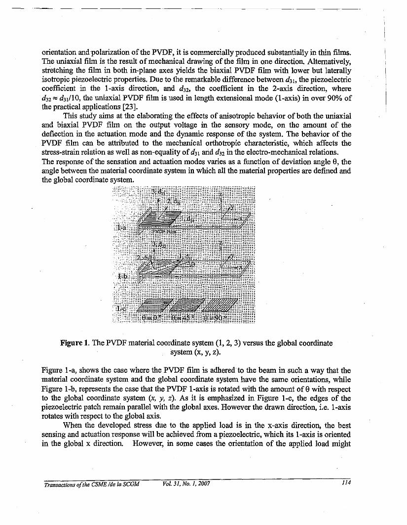
This study aims at the elaborating the effects of anisotropic behavior of both the uniaxialand biaxial PVDF film on the output voltage in the sensory mode, on the amount of thedeflection in the actuation mode and the dynamic response of the system. The behavior of thePVDF film can be attributed to the mechanical orthotropic characteristic, which affects thestress-strain relation as well as non-equality of d31 and d32 in the electro-mechanical relations.The response of the sensation and actuation modes varies as a function of deviation angle e, theangle between the material coordinate system in which all the material properties are defined andthe global coordinate system.
Figure 1. The PVDF material coordinate system (1, 2, 3) versus the global coordinatesystem (x, y, z).
Figure I-a, shows the case where the PVDF film is adhered to the beam in such a way that thematerial coordinate system and the global coordinate system have the same orientations, whileFigure I-b, represents the case that the PVDF I-axis is rotated with the amount ofewith respectto the global coordinate system (x, y, z). As it is emphasized in Figure I-c, the edges of thepiezoelectric patch remain parallel with the global axes. However the drawn direction, i.e. I-axisrotates with respect to the global axis.
When the developed stress due to the applied load is in the x-axis direction, the bestsensing and actuation response will be achieved from a piezoelectric, which its I-axis is orientedin the global x direction. However, in some cases the orientation of the applied load might
Transactions ofthe CSME Ide la SCGM Vol. 31, No.1, 2007 114
result in a two-dimensional stress profile and thus finding the best orientation to attach the.piezoelectric· film is important. The rotation between the material property and the globalcoordinate system can also occur inadvertently during the manufacturing phase of a sensor.Obviously by simply considering PVDF as an isotropic material, no alterations in the responsesin terms ofdeviation angle would be observed.
3. THE CONSTITUTIVE EQUATIONS
The linear constitutive equations for the orthotropic piezoelectric crystals in the principle
material coordinates assuming a constant temperature (i.e. IIT~O) are given by Reddy [24]:
{a} =[C]{e} -renE}{D} =[e]{e} -[g]{E}
(1)
(2)
where [C].x. is the stiffuess matrix, [e].x3 the piezoelectric coupling matrix, {e} 6xI the strain
field and [g]3x3 the permittivity matrix. The bar sign indicates the transformed quantities from
material axis to global axis which is obtained using [C] =[TO"r [cIT.], in which [TO" ] and [T,,]represent the transformation matrices corresponding to stress vector, a and strain vector 8.
{ahXl represents the stress vector, {DhXI the electric displacement and {EhXI the electric field.
The piezoelectric coupling matrices[e], (cjm2), and [il] ,( C / N), are related by [e] =[C][d] .
Equation (1) describes the inverse piezoelectric effect while Equation (2) describes the directpiezoelectric effect. It is noted that components of the stiffuess matrix [C].x. are functions of
deviation angle a . For instance the first and last components of [C].x. are described as:
C66 = 2(C16 - C26 )COs3 a ... sina + (Cn + C22 -2C12 -2C66)COs2 a sin2 a
+ 2(C26 - C16)COSa sin3 a +C66(COS4 a +sin4 a)
Due to the thiimess of the films, one can avoid the complexity ofa 3D analysis and still preservethe reasonable accuracy ofthe obtained results from the reduced in-plane formulation. Equations.(1) and (2) can be derived for 2-D plate element simply by neglecting stresses through thethickness and compute the resultant components for stiffuess matrix. Similarly a beam elementcan be obtained by considering ouly axial and transverse shear stress in Equation (1) andconsidering electrical displacement in thickness direction in Equation (2). For details regardingthe piezoelectric plate and beam elements one may consUlt the book written by Reddy [24].
Transactions ofthe CSME Ide 10 SCGM Vol. 31, No. 1,2007 llS

---...-- .._-- ---
4. FINITE ELEMENT FORMULATION
--.--
The mechanical response of the piezoelectric material with the coupled mechanical and electricalproperties is represented by the stress equation ofmotion [25]:
(3)
while the electrical response is described by the electrostatics equation for the conservation ofthe electric flux,
D., =0I, (4)
where p is the density, f is the body force, superscript dots represents time derivatives andsubscript commas represents differentiation with respect to space. Neglecting the body force andusing divergence theorem, the combined electro-mechanical response of the piezoelectricmaterial is determined as:
J(PUiOUi +uijoeij -D,oEJlV = Jt,ou,dI'+ JqolfldI'v r/ rp
(5)
where ui are the generalized displacements, t, are the surface tractions applied on the surface r,and q is the electrical charge applied on the surface r p of the piezoelectric material and V
represents the whole volume including the piezoelectric and substrate materials.As mentioned before, for the sake of simplicity, the finite element formulation is expressed for abeam model. It should be noted that the Equation (5) is a general equation and can be applied toobtain any kind ofelements. The displacement fields for a Kirchhoffbeam element are given by:
Owu(x,z,t)=uo(x,t)-z_o, w(x,z,t) =wo(x,t)ax (6)
where Uo(x) and wo(x) denote the displacements of the reference point at x, y and z axis,
respectively. The finite element matrix equation of the piezoelectric beam element can beobtained by implementing Equation (6) into Equation (5) and collecting the coefficients as:
[M O]{{~}}+[[KUU] [Ku~]l{{U}}={{F(t)}}o 0 {<I>} [K~u] [K~ ~ {<I>} (Q(t)}
(7)
where {U}={{u} {wlY and the submatrices [Kuu ], [K~u], [K~] indicate the elastic,
piezoelectric, and the permittivity matrices;. [M] is the mass matrix; {F} are the applied forces;
and {Q}are the applied voltages. From Equations (1), (2) and (5), one may realize that the
Transactions ofthe CSME Ide la SCGM Vol. 31, No.1. 2007 JJ6
submatrices [Kuu ], [K",u] and [K",,,,] are all functions ofdeviationanglee. Equation (7) can be
partitioned into .the sensing and actuating components as follows:
(8)
where the superscripts s and a indicate the partitioned submatrices in accordance with thesensing and actuating modes, respectively. The left hand side indicates the unknowndisplacement and voltage at the sensor and the right hand side represents the known appliedmechanical load and voltage on the actuator.
5. NUMERICAL EXAMPLES
In order to clarify the anisotropic behavior of the PVDF fibn governed by. the above-mentionedequations, in this section, the effects of orthotropic properties on a variety of the outputresponses have been investigated. An Aluminum cantilever beam with surface boundedsensor/actuator, as shown in Figure 1, is considered for the numerical simulations. In all thefollowing numerical results, the length and width of the beam are considered to be 0.245 m and0.0245 m, respectively. The thickness of the beam for the sensing mode is considered to be 2mm, while in the actuation mode it is varied to show the effect of the thickness ratio on the beamresponse. Both the uniaxial and biaxial 25-llm PVDF fibns are examined in the sensing as wellas the actuation mode.The stiffuess coefficients for unidirectional PVDF are{ell' Ct2 , C13 , C22 , C23 , C33 , CM> CSS ' C66 }={3.7, 1.47, 1.23, 3.2, 1.0, 1.51, 0.55, 0.59, 0.7} GPa
and the piezoelectric coefficients{dIS' d w d31' d 32 , d33 }={-27, -23, 18, 2, -20}xlO-t2 C/m2
•
The material properties ofAluminum are given as: E=70 GPa, v =0.30, p=2712 kg/m3•
The beam is meshed with 20 equal-length elements and PVDF fibn is bonded at the firstthree elements. In the sensing mode, a downward F=lO N point load is exerted at the tip while inthe actuation mode the applied voltage to the piezoelectric patch is 240 V and load is removed.
5.1. Sensing Mode: The Effect of Orientation on the"Output VoltageIn the following simulations, due to the firm adherence of the piezoelectric patch, it is
assumed that the strain in the PVDF fibn is the same. as the strain developed in the beam due tothe applied load. To show the difference between the isotropic (i.e. Biaxial PVDF) and theorthotropic (Uniaxial PVDF), simulations are carried out for both materials. In the followingtests, as illustrated in Figure 1, the deviation angle, the angle between the I-axis in materialcoordinate system and the x-axis in the global coordinate system, is varied from 0 to 90°.
5.1.1. Biaxial PVDFThe piezoelectric coefficients of the biaxial PVDF are equal in the I-axis and the
transverse direction, 2-axis. In other words, the ratio ofd3Jdn , for the biaxial PVDF fibn is
Transactions oflhe CSME Ide la SCGM Vol. 31. No.1. 2007 117
------~~------------ ---------
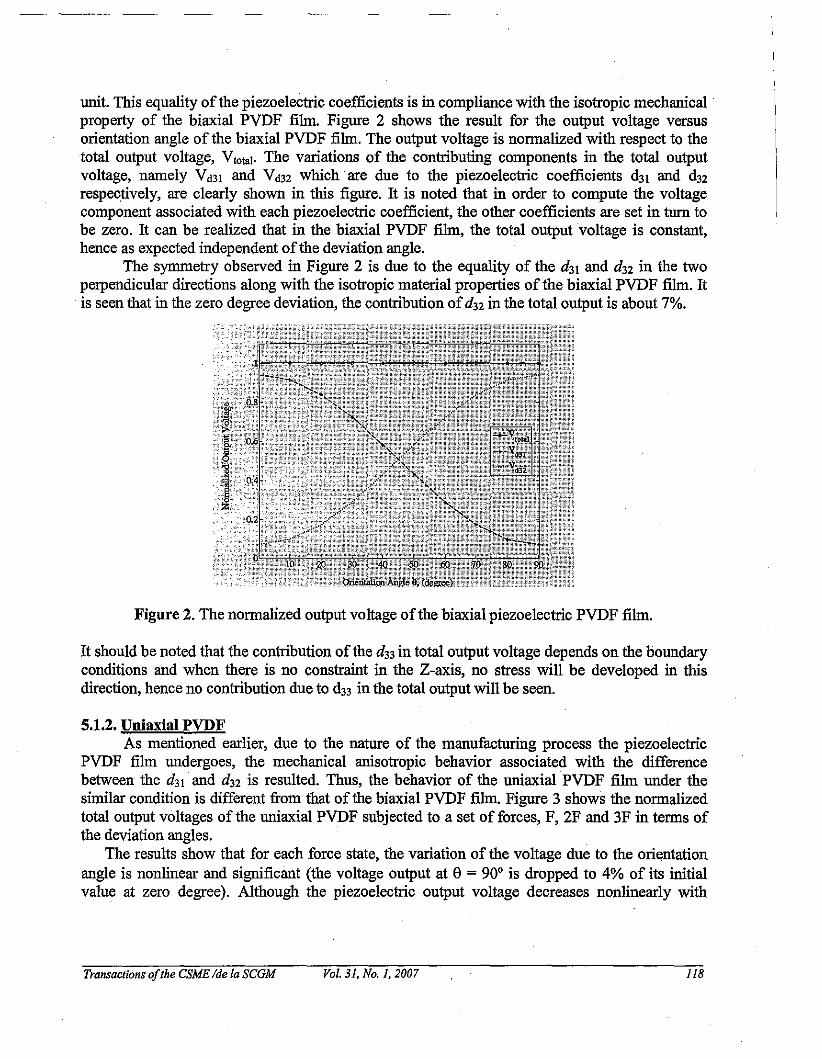
unit. This equality ofthe piezoelectric coefficients is in compliance with the isotropic mechanical .property of the biaxial PVDF film. Figure 2 shows the result for the output voltage versusorientation angle of the biaxial PVDF film. The output voltage is normalized with respect to thetotal output voltage, Vtolal • The variations of the contributing components in the total outputvoltage, namely Vd3l and Vd32 which are due to the piezoelectric coefficients d31 and d32respectively, are clearly shown in this figure. It is noted that in order to compute the voltagecomponent associated with each piezoelectric coefficient, the other coefficients are set in turn tobe zero. It can be realized that in the biaxial PVDF film, the total output voltage is constant,hence as expected independent of the deviation angle.
The symmetry observed in Figure 2 is due to the equality of the d31 and d 32 in the twoperpendicular directions along with the isotropic material properties of the biaxial PVDF film. Itis seen that in the zero degree deviation, the contribution ofd32 in the total output is about 7%.
Figure 2. The normalized output voltage ofthe biaxial piezoelectric PVDF film.
It should be noted that the contribution of the d33 in total output voltage depends on the boundaryconditions and when there is no constraint in the Z-axis, no stress will be developed in thisdirection, hence no contribution due to d33 in the total output will be seen.
5.1.2. Uniaxial PVDFM mentioned earlier, due to the nature of the manufacturing process the piezoelectric
PVDF film undergoes, the mechanical anisotropic behavior associated with the differencebetween the d31 and dn is resulted. Thus, the behavior of the uniaxial PVDF film under thesimilar condition is different from that of the biaxial PVDF film. Figure 3 shows the normalizedtotal output voltages of the uniaxial PVDF subjected to a set offorces, F, 2F and 3F in terms ofthe deviation angles.
The results show that for each force state, the variation of the voltage due to the orientationangle is nonlinear and significant (the voltage output at e = 900 is dropped to 4% of its initialvalue at zero degree). Although the piezoelectric output voltage decreases nonlinearly with
Transactions ofthe CSME Ide la SCGM Vol. 31, No. 1.2007 lIB
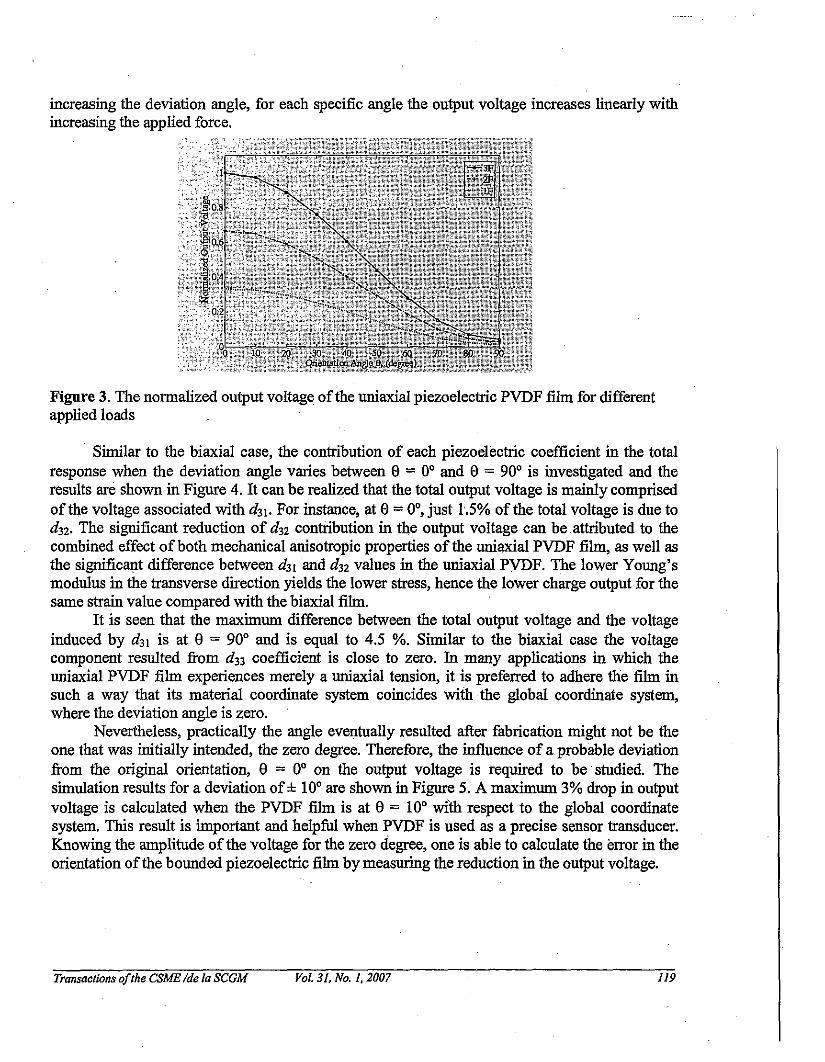
increasing the deviation angle, for each specific angle the output voltage increases linearly withincreasing the applied force. .
Figure 3. The normalized output voltage ofthe uniaxial piezoelectric PVDF fihn for differentapplied loads
. Similar to the biaxial case, the contribution of each piezoelectric coefficient in the totalresponse when the deviation angle varies between e = 0° and e = 90° is investigated and theresults are shown in Figure 4. It can be realized that the total output voltage is mainly comprisedof the voltage associated with d31. For instance, at e= 0°, just 1.5% of the total voltage is due tod 32• The significant reduction of d32 contribution in the output voltage can be attributed to thecombined effect of both mechanical anisotropic properties of the uniaxial PVDF fihn, as well asthe significant difference between d31 and d 32 values in the uniaxial PVDF. The lower Young'smodulus in the transverse direction yields the lower stress, hence the lower charge output for thesame strain value compared with the biaxial fihn.
It is seen that the maximum difference between the total output voltage and the voltageinduced by d31 is at e = 90° and is equal to 4.5 %. Similar to the biaxial case the voltagecomponent resulted from d33 coefficient is close to zero. In many applications in which theuniaxial PVDF fihn experiences merely a uniaxial tension, it is preferred to adhere the fihn insuch a way that its material coordinate system coincides with the global coordinate system,where the deviation angle is zero.
Nevertheless, practically the angle eventually resulted after fabrication might not be theone that was initially intended, the zero degree. Therefore, the influence of a probable deviationfrom the original orientation, e = 0° on the output voltage is required to be studied. Thesimulation results for a deviation of± 10° are shown in Figure 5. A maximum 3% drop in outputvoltage is calculated when the PVDF fihn is at e = 10° with respect to the global coordinatesystem. This result is important and helpful when PVDF is used as a precise sensor transducer.Knowing the amplitude ofthe voltage for the zero degree, one is able to calculate the error in theorientation ofthe bounded piezoelectric fihn by measuring the reduction in the output voltage.
Transactions ofthe CSME Ide la SCGM Vol. 31, No. 1,2007 119

Figure 4. The normalized output voltage of the uniaxial piezoelectric PVDF film versusdeviation angle.
Figure 5. Variation of the normalized output voltage ofuniaxial PVDF file versus ±10 degreedeviation angle
5.2. Actuation Mode: The Effect of Orientation on the DeflectionIn order to study the effect oforientation of the attached orthotropic PVDF actuator on the
tip deflection, a cantilever beam described in Section 5 is considered. In the actuation mode,similar to the sensing mode, the tip deflection is constant for all deviation angles when biaxialPVDF is used. However for the uniaxial PVDF, the tip deflection is a function of the deviationangle. On the other hand, the deflection values also depend on the geometries of the PVDF andthe beam. The variations of tip deflection versus rotation angle e= 0 to 90 ° and for the differentthickness ratios Hb/ H p (Hb is the thickness of the beam and Hp is the thickness of the PVDF)
are shown in Figure 6. It should be noted that Hb / Hp = 20 curve is used as the reference
normalized curve. It is observed that the maximum effect exists for the thinner beams (or thethicker PVDFfilms). For instance, whenHb/Hp = 20, the deflection at 90° drops to 12 % of itsinitial value at 0°. When the thickness of the PVDF film is much lower than the thickness of the
Transactions ofthe CSME Ide la SCGM Vol. 31, No.1. 2007 120

beam, the sensitivity to the deviation angle reduces remarkably. For example for Hb/Hp = 40,
the deflection at 90° is 10% of the 0° value. Therefore for some applications such as MEMS,where the thickness of the PVDF tihn and the beam could be of the same order ofmagnitude, thedeviation angle plays an important role. Similar performance in the sensing mode and in theactuation mode can be observed by comparing the graphs in Figures 3 and 6.
Figure 6. The normalized tip deflection of the beam versus the deviation angle of the uniaxialPVDFpatch.
5.3. Effect of Orientation on the Dynamic ResponseThe effect of the uniaxial PVDF tihn orientation on the free undamped vibration response,
using the similar cantilever beam and PVDF tihn explained in Section 5, is investigated. For freevibration response the equation (7) is reduced to
(9)
Considering U = Uoe-im, and substituting in Equation (9) leads to the following eigenvalue
problem:
(10)
where [K]=[Kuu]-[K~u][K~<I>rl[K~u]and ll.=w 2• As mentioned earlier the generalized
stiffuess [K] is a function of deviation angle e. Equation (10) has been solved for angles
e=0° - 90° and the variation of the normalized fundamental frequency (ratio of fundamentalfrequency at deviation angle to fundamental frequency at deviation angle of zero) with respect toply orientation angle for the PVDF layer is demonstrated in Figure 7.
Transactions ofthe CSME Ide la SCGM. Vol. 31, No.1, 2007 121
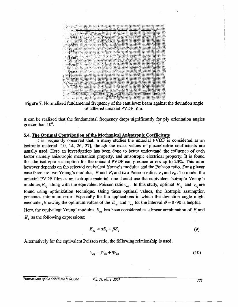
Figure 7. Nonnalized fundamental frequency ofthe cantilever beam against the deviation angleofadhered uniaxial PVDF film.
It can be realized that the fundamental frequency drops significantly for ply orientation anglesgreater than 100
•
5.4. The Optimal Coutribution of the Mechanical Anisotropic CoefficientsIt is frequently observed that in many studies the uniaxial PVDF is considered as an
isotropic material [10, 14, 26, 27], though the exact values of piezoelectric coefficients areusually used. Here an investigation has been. done to better understand the influence of eachfactor namely anisotropic mechanical property, and anisotropic electrical property. It is foundthat the isotropic assumption for the uniaxial PVDF can produce errors up to 20%. This errorhowever depends on the selected equivalent Young's modulus and the Poisson ratio. For a planarcase there are two Young's modulus, E, and E2 and two Poisson ratios V12 and V 21 • To model theuniaxial PVDF film as an isotropic material, one should use the equivalent isotropic Young'smodulus,Eeq along with the equivalent Poisson ratioveq' In this study, optimal Eeq and veqare
found using optimization technique. Using these optimal values, the isotropic assumptiongenerates miJ:rimum error. Especially for the applications in which the deviation angle mightencounter, knowing the optimum values of the Eeq and Veq for the interval e= 0 -90 is helpful.
Here, the equivalent Young' modulus Eeq has been considered as a linear combination of E1and
E 2 as the following expressions:
(9)
Alternatively for the equivalent Poisson ratio, the following relationship is used.
Tra~sactions ofthe CSME /de la SCGM Vol. 3J, No. J, 2007
(10)
J22
------------------- _ .. _ .. _------

The optimization problem is to determine the values of coefficients a,p,r,and 17 (design
variables) in order to minimize the error between the deflection obtained based on the set ofE"
E 2 , VI2 and V21 and the deflection calculated based on the equivalent Eeq and veq(objective
function). Logically the Equivalent Young's modulus must be less than El and greater than Ez.Thus the following constraint relationships for the Young's modulus and the Poisson ratiosshould be satisfied.
(11)
Therefore, the design variables a,P,r,17 are bounded in the interval [0, I].Since the deflection of cantilever beam is nonlinear in nature, the above optimization
problem is a nonlinear constraint problem. An optimization algorithm based on the finite elementformulation (analysis module) and the Sequential Quadratic Programming (SQP-optimizationmodule [28]) has been developed to find the optimal values ofcoefficients a, P, r, and 17.
The cantilever beam with surface bounded piezoelectric patches described in Section 5 isconsidered for numerical illustration. The optimum values for a,P,r,17 are determined and the
non-dimensional equivalent values for E,. and v,. are presented in Table 2. Close observation
of these results reveals that, to minimize the error for all angles, one may consider 95% of E,
and 5% ofE 2 and also 72% of VI2 and 28% of V2,.
Table 2. The equivalent material properties for different deviation angles.
PVDP orientation angle, e0 IS 30 45 60 75 90
a 0.8475 0.8495 0.8502 0.8499 0.8479 0.8482 0.8417B 0.1524 0.1505 0.1498 0.1500 0.1527 0.1517 . 0.1518y 0.00094 0.0000 0.00066 0.00064 0.00097 0.00078 0.02005n 0.99905 1.0000 0.99933 0.99936 0.99903 0.99921 0.97995
EeqIE! 0.95862 0.95923 0.95943 0.95927 0.95924 0.95881 0.95238
Veq IV!2 0.72574 0.72549 0.72566 0.72566 0.72575 0.72569 0.73099
Errorx 10-7 0.37 0.93 9.50 0.50 9.40 10.0 5.34
6. CONCLUSIONS
The influence of the sensor/actuator orientation on the system performance including outputvoltage in sensory mode, nodal displacements in the actuation mode and natural frequency hasbeen investigated. Both biaxial and uniaxial piezoelectric PVDP films have been considered inthis inve~tigation when the deviation angle changes between zero to 90 degree. The outcome ofthis study indicates the same descending trend in the response amplitude for all three sets ofsimulations, namely, sensation, actuation and fundamental natural frequency of the structure.
Transactions ofthe CSME Ide la SCGM Vol. 31, No.1, 2007 123

In the sensory mode the contributions of piezoelectric coefficients includingd31 ,d32 and d33
have been studied. It is observed that the output of the biaxial PVDF film is independent on thedeviation angle, hence is appropriate for the applications in which the constant output is requiredregardless of the force orientation. Conversely the output of the uniaxial PVDF film is highlydependent on the orientation angle. Having characterized the relationship between the deviationangle and the output response, one can compensate any attenuation due to probablemisalignment. Furthermore this can be potentially helpful to find the orientation of the appliedload in the force-position applications. To avoid computational complexity of the orthotropicmaterials, without sacrificing the accuracy of the problem, an investigation performed in order tofind the optimum equivalent isotropic properties. These equivalent properties (E..and veq )
minimize the output error for the whole range of deviation angles. The equivalent materialproperties have been determined through a formal optimization procedure. It has been observedthat considering 95% of axial and 5% of transverse material properties can provide resultssimilar to orthotropic one with negligible error. These data potentially could be useful whenuniaxial PVDF film is used and the orientation of the force respect to the film axes might vary,such as PVDF film attached to a membrane.
REFERENCES
1. Kawai, H., "The piezoelectricity ofPolyvVinylidene Fluoride", Jpn. J. Applied Physics,Vol. 8, 1969, pp. 975-6.
2. Pereira, D., Shankar, V. N., Sathiyanaarayan, S., Lakshmana, R. C. and Sivakumar, S.M., "Vibration control ofa cantilever beam using distributed PVDF actuator", Proc. ofSPIE-The Int. Society for Optical Engineering, Vol. 5062, No.2, 2002, pp. 598-604.
3. De Abreu, Gustavo, L. C. M., Riberio J. F. and Steffen Jr. V., "Digital optimal vibrationcontrol of a flexible structure containing piezoelectric elements", Proc. of the 2003ASME Design Engineering Technical Conferences and Computers and Information inEngineering Conference. Volume 5: 19th Bienuial Conference on Mechanical Vibration
. andNoise, pp.1739-1748.4. Wang, D. H. and Huang, S. L. "Health monitoring and diagnosis for flexible structures
with PVDF piezoelectric film sensor array", Journal of Intelligent Material Systems andStructures, VoUl, No.6, 2000, pp. 482-491.
5. Hurlebaus, S. and Gaul L., "Smart layer for damage diagnostics", Journal of IntelligentMaterial Systems and Structures, Vol. 15, No. 9-10, 2004, pp. 729-736.
6. Lee, Y. S., Elliott, S. J. and Ganrdonio, P. "Distributedfour-layer PVDF actuator/sensorarrangement for the control ofbeam motion", Proc. of SPIE - The International Societyfor Optical Engineering, Vol. 4326, 2001, pp. 284-294.
7. Sokhanvar, S., Packirisamy, M. and Dargahi, J., "A Novel PVDF Based Softness andPulse Sensor for Minimally Invasive Surgery", the Third IEEE International Conferenceon Sensors, Austria, 2004 , pp. 24-27.
8. Airmar Teclmology Corporation, New Hampshire 03055-4613 USA,http://www.airmar.com
9. Goodfellow, 237 Lancaster Avenue, Suite 252, DEVON PA, 19333-1594, USA,www.goodfellow.com
Transactions ofthe CSME Ide 10 SCGM Vol. 31, No.1, 2007 124
10. Ueberschlag, P., "PVDF piezoelectric polymer', Sensor Review, Vol. 21, No 2, 2001,pp.I18-125.
II. Vel, S. S. and Batra, R. C., "Three- Dimensional Analytical solution for hybridmultylayerdpiezoelectric plates", Transactions of ASME, Vol. 67,2000, pp. 558.
12. Yongrae, R. and Vasundara, V., "Characterization of all the elastic, dielectric, andpiezoelectric constants ofuniaxially oriented poled PVDFfilms", IEEE Transactions on
. Ultrasonics, Ferroe1ectrics, and Freq. Cont. , Vol. 49, No.6., 2002.13. Tasaka, S. and Miyata, S., "The origin ofPiezoelectricity in Poly (vinylidene Fluoride)",
Ferroe1ectrics, Vol. 32, pp 17-23.14. Lue, H., and Hanagud, S., "PVDFfilm sensor and its applications in Damage detection",
Journal ofAerospace Engineering, 1999, pp. 23-30.15. Bloomfield, P. E., "Production offerroelectric oriented PVDFfilms", J. Plastic Film and
Sheeting, Vol. 4, No.2, 1988, pp. 123-129.16. Yuhuan, x., "Ferroelectric Materials and their applications", North-Ho1and, 1991.17. Sakata, J. and Mochizuki, M., "Preparation of organic thin films by an electrospray
technique L Crystalforms and their orientation in Poly(Vinylidene Fluoride) films", ThinSolid Films, 195, 1991, pp 175-184.
18. Asahi, J. and Sakata; J., "Integrated pyroelectric infrared sensor using PVDF thin filmdeposited by electro-spray method", Mat. Res. Soc. Symp. Proc.Vol.31O, 1993, pp 79-84.
19. Binnie, T. D., "An Integrated 16*16 PVDF Pyroelectric Sensor Array", IEEETransactions on Ultrasonics, and Frequency Control, Vol. 47, No.6, 2000.
20. Weller, H. J., Setiadi D. and Binnie T. D., "Low-noise charge sensitive readout forpyroelectric sensor arrays using PVDF thin film", Sensors and Actuators, Vol. 85,2000,pp.267-274.
21. Spearritt, D. J., and Asokanthan, S. F., "Torsional vibration control of a jlexible beamusing laminated PVDF actuators", Journal of Sound and Vibration Vol. 193, No 5, 1996,pp 941-956.
22. Nye, J. F. ,"Physicalproperties ofcrystals", Oxford, 1960.23. Thompson, M. 1., "On the materialproperties and constitutive equations ofpiezoelectric
polyvinylidenejluoride (PVDF)", PhD thesis, Nov 2002, Drexel University.24. Reddy, J. N., "Mechanics of laminated comppsite plates: theory and analysis", CRC
Press Inc., 1997..25.IEEE Standards on Piezoelectricity, ANSIlIEEE Std.: 176-1987, The Institute of
Electrical and Electronic Engineers Inc.26. Dargahi, J., Parameswarp., M. and Payandeh, S., "Michromachined piezoelectric tactile
sensor for an endoscopic grasper- theory, fabrication and experiments", Journal ofMicroe1ectromechanica1 Systems, Vol. 9, No 3, 2000, pp 329-335.
27. Chen, S. H., Yao, G. F. and Huang, C.,"A new intelligent thin-shell element", SmartMater. Struct., Vol. 9, 2000, pp 10-18.
28. Arora, J. S., Introduction to Optimization Design, McGraw Hill, NewYork, 1989.
Transactions ofthe CSME Ide la SCGM Vol. 31, No.1, 2007 125