Embed Size (px)
Citation preview
ALCATEL VACUUM TECHNOLOGY FRANCE98, avenue de Brogny --- BP 206974009 ANNECY Cedex --- France
TEL. (33) 4 50 65 77 77FAX : (33) 4 50 65 77 89
IPUP A100 Instruction manual
Edition: 10Date: 09/00
Manual P/N 107782
Alcatel Vacuum Technology France --- IPUP A100 Instruction manual 1 / 2
IPUP A100
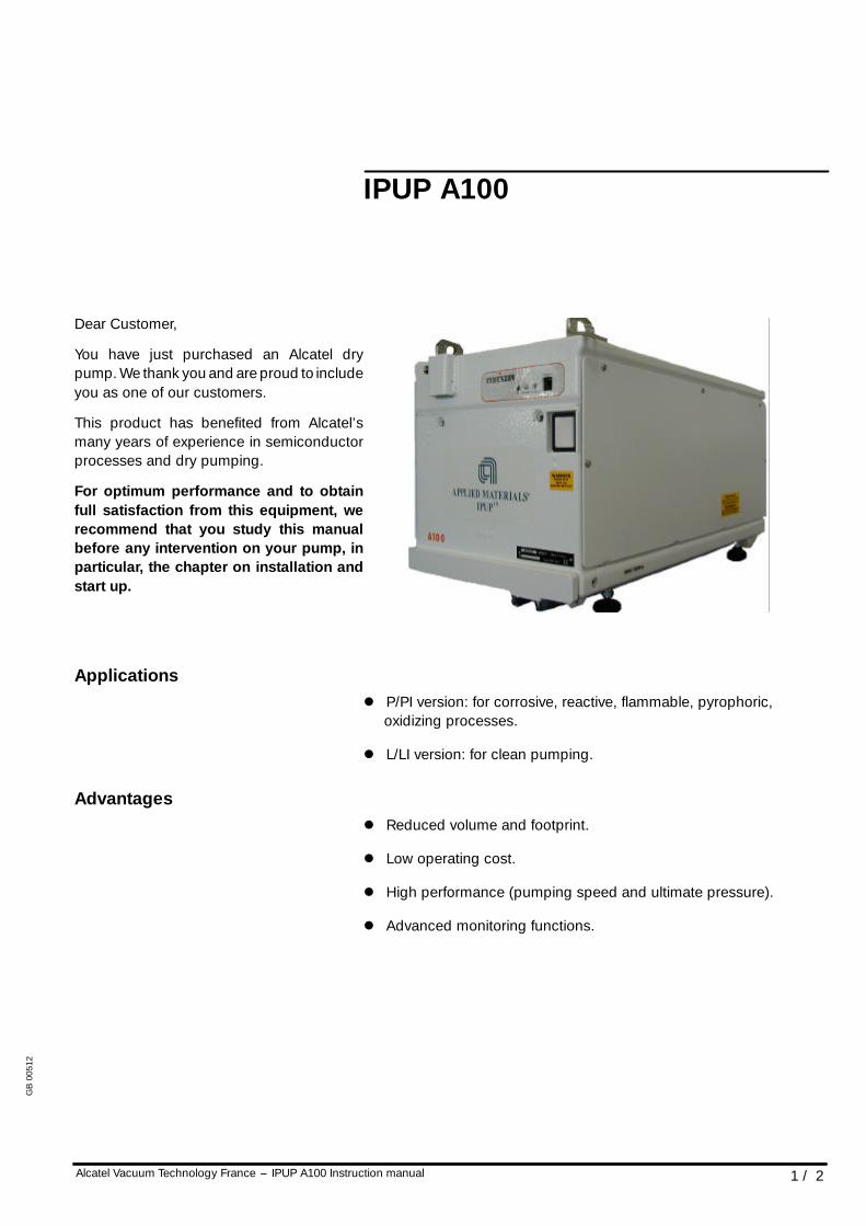
Dear Customer,
You have just purchased an Alcatel drypump. We thank you and are proud to includeyou as one of our customers.
This product has benefited from Alcatel’smany years of experience in semiconductorprocesses and dry pumping.
For optimum performance and to obtainfull satisfaction from this equipment, werecommend that you study this manualbefore any intervention on your pump, inparticular, the chapter on installation andstart up.
Applicationsl P/PI version: for corrosive, reactive, flammable, pyrophoric,
oxidizing processes.
l L/LI version: for clean pumping.
Advantagesl Reduced volume and footprint.
l Low operating cost.
l High performance (pumping speed and ultimate pressure).
l Advanced monitoring functions.
GB
0051
2
2 / 2 Alcatel Vacuum Technology France --- IPUP A100 Instruction manual
IPUP A100
Special featuresl Multi---stage Roots technology.
l Water---cooled motor.
Multi ---stage pump with rootstechnology
l Established technology.
Low noise and vibration
Genuine dry pumpl Total tightness with the environment.
Compact footprintl Reduced size 23.84 inches x 11.02 inches x 11.81 inches.
(605.5 mm x 280 mm x 300 mm).
Reduced cost of ownershipl Design for reliability.
l Reduced power consumption.
l Reduced water consumption.
l Reduced weight.
New control interfacel Amat SPI interface.
l Amat device net interface.
l RS 232/485 interface.
GB
0051
2
Contents
Alcatel Vacuum Technology France --- IPUP A100 Instruction manual 1 / 3
IPUP A100 instruction manual
IntroductionIPUP A100 operating principle A 10. . . . . . . . . . . . . . .
IPUP A100 description A 20. . . . . . . . . . . . . . . . . . . . .
IPUP A100 monitoring system A 30. . . . . . . . . . . . . . .
IPUP A100 technical characteristics A 40. . . . . . . . . .
Table of IPUP A100 part numbers A 50. . . . . . . . . . . .
CE marking certificate A 60. . . . . . . . . . . . . . . . . . . . .
SEMI S2 certificate A 70. . . . . . . . . . . . . . . . . . . . . . . .
Start upSafety instructions B 00. . . . . . . . . . . . . . . . . . . . . . . .
Unpacking / Handling / Storage B 10. . . . . . . . . . . . .
Positioning the pump in the pumping installation B 20
Connection to the cooling circuit B 30. . . . . . . . . . . . .
Inert gas purge connection (N2 connection) B 40. . . .
Electrical connection B 50. . . . . . . . . . . . . . . . . . . . . .
Amat smart pump interface connection B 60. . . . . . .
RS 232 or RS 485 link wiring B 70. . . . . . . . . . . . . . . .
Connection to the pumping circuit B 80. . . . . . . . . . .
OperationOperating mode C 10. . . . . . . . . . . . . . . . . . . . . . . . . .
Start up of the monitoring system C 20. . . . . . . . . . . .
Use of the monitoring system for pumpingoperation C 30. . . . . . . . . . . . . . . . . . . . . . . . . . . . . . .
Monitoring system parameters C 40. . . . . . . . . . . . . .
Monitoring system function tableIPUP A100P version C 50. . . . . . . . . . . . . . . . . . . . . . .
GB
0051
3
Contents
2 / 3 Alcatel Vacuum Technology France --- IPUP A100 Instruction manual
IPUP A100 instruction manual
Operation (cont’d)Monitoring system function tableIPUP A100L version C 51. . . . . . . . . . . . . . . . . . . . . . .
Gas purge and temperature according to thesemiconductor processes C 60. . . . . . . . . . . . . . . . . .
Saving and loading of pump configuration(with monitoring system) C 70. . . . . . . . . . . . . . . . . . . . .
Monitoring system setting for transport C 80. . . . . . .
Use of the serial link C 90. . . . . . . . . . . . . . . . . . . . . . .
TroubleshootingFirst level of troubleshooting D 10. . . . . . . . . . . . . . . . . .
Diagnosis and troubleshooting D 20. . . . . . . . . . . . . . . .
Message numbers D 30. . . . . . . . . . . . . . . . . . . . . . . . . .
Pump does not start.Hand held display module is not illuminated D 40. . . .
Pump does not start.IPUP A100 without hand held display module D 50. . .
Pump does not start.Hand held display module is illuminated D 60. . . . . . .
Pump does not start.Display is showing a message or an alarm D 70. . . . .
Fault message display.Facilities problem D 80. . . . . . . . . . . . . . . . . . . . . . . . . . .
Fault message display.Temperature problem D 90. . . . . . . . . . . . . . . . . . . . . . . .
Fault message display.Pressure problem D 100. . . . . . . . . . . . . . . . . . . . . . . . . . .
Fault message display.Maintenance problem D 110. . . . . . . . . . . . . . . . . . . . . . . .
Pump is running.No message D 120. . . . . . . . . . . . . . . . . . . . . . . . . . . . . . . .
GB
0051
3
!WARNING
!CAUTION
Contents
Alcatel Vacuum Technology France --- IPUP A100 Instruction manual 3 / 3
IPUP A100 instruction manual
Maintenance instructionsMaintenance frequency E 10. . . . . . . . . . . . . . . . . . . .
Shipping procedure for contaminated pumps E 20. .
Maintenance componentsN2 pressurization kit F 10. . . . . . . . . . . . . . . . . . . . . . . . .
AppendixIPUP A100 electrical block diagram G 10. . . . . . . . . . . .
Safety data sheet G 20. . . . . . . . . . . . . . . . . . . . . . . . . . .
Accessory part numbers G 30. . . . . . . . . . . . . . . . . . . . .
NOTE
Warnings are used when failure to observe instructions couldresult in injury or death.
Cautions are used when failure to observe instructions couldresult in significant damage to equipment and/or facilities.
GB
0051
3
Chapter A
Alcatel Vacuum Technology France --- IPUP A100 Instruction manual 1 / 1
IPUP A100 instruction manual
IntroductionIPUP A100 operating principle A 10. . . . . . . . . . . . . . .
IPUP A100 description A 20. . . . . . . . . . . . . . . . . . . . .
IPUP A100 monitoring system A 30. . . . . . . . . . . . . . .
IPUP A100 technical characteristics A 40. . . . . . . . . .
Table of IPUP A100 part numbers A 50. . . . . . . . . . . .
CE marking certificate A 60. . . . . . . . . . . . . . . . . . . . .
SEMI S2 certificate A 70. . . . . . . . . . . . . . . . . . . . . . . .
GB
0051
4
A 10
1 / 3Alcatel Vacuum Technology France --- IPUP A100 Instruction manual
IPUP A100 operating principle
DESIGN TO MINIMIZEPOTENTIEL RESIDUES
The equipment was designed to minimize potentiel residue deposits:
l by limiting the internal volumes that contain gas,
l by injecting N2 purge on each pump stage to dilute the processgas (P version only),
l by regulating the pump temperature and adjusting it to eachprocess in order to limit gas condensation (P version only),
l by integrating the silencer inside the pump to reduce by---productdeposition.
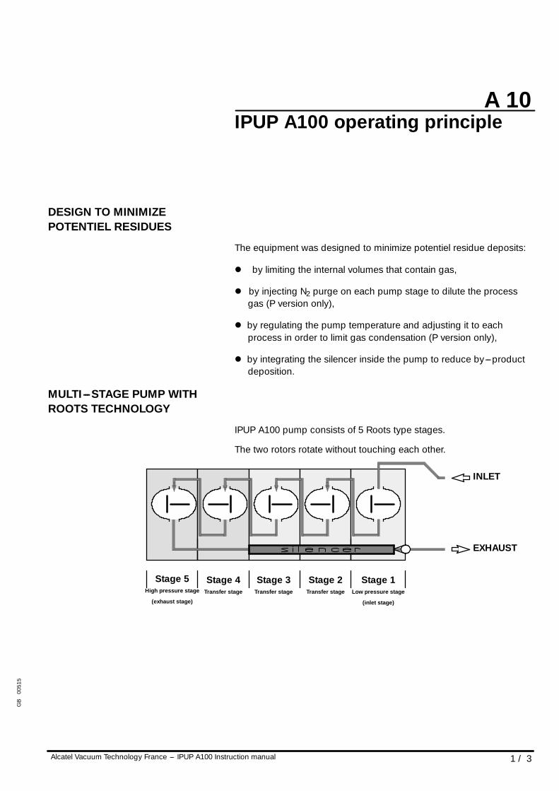
MULTI---STAGE PUMP WITHROOTS TECHNOLOGY
IPUP A100 pump consists of 5 Roots type stages.
The two rotors rotate without touching each other.
EXHAUST
INLET
Stage 5High pressure stage
(exhaust stage)
Stage 4Transfer stage
Stage 3Transfer stage
Stage 2Transfer stage
Stage 1Low pressure stage
(inlet stage)
GB
0051
5
A 10
2 / 3 Alcatel Vacuum Technology France --- IPUP A100 Instruction manual
IPUP A100 operating principle
TIGHTNESS WITH ENVIRONMENT
Tightness at low pressure sideThe pump is fitted with ball bearings lubricated with fluorinated grease.
An overpressure zone is created around the bearing by injecting aneutral gas.
The pressurization and the seals prevent pumped gases and powdersfrom migrating towards the bearings.
Neutral gas purging for the bearings is imperative for corrosiveprocesses.
Tightness at high pressure sideThe bearings are lubricated by splashing oil.
The oil trap is sealed from stage 5 by a trap and a deflector.
GB
0051
5
A 10
3 / 3Alcatel Vacuum Technology France --- IPUP A100 Instruction manual
IPUP A100 operating principle
TIGHTNESS WITH ENVIRONMENT(CONT’D)
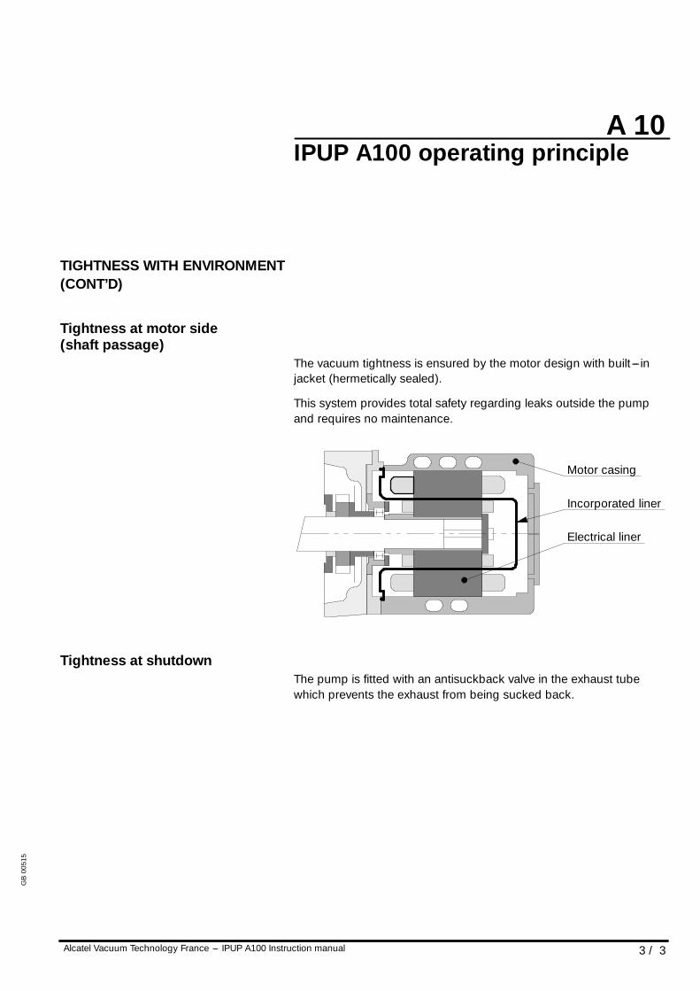
Tightness at motor side(shaft passage)
The vacuum tightness is ensured by the motor design with built --- injacket (hermetically sealed).
This system provides total safety regarding leaks outside the pumpand requires no maintenance.
Motor casing
Electrical liner
Incorporated liner
Tightness at shutdownThe pump is fitted with an antisuckback valve in the exhaust tubewhich prevents the exhaust from being sucked back.
GB
0051
5
A 20
1 / 3Alcatel Vacuum Technology France --- IPUP A100 Instruction manual
IPUP A100 description
IPUP A100 DESCRIPTION
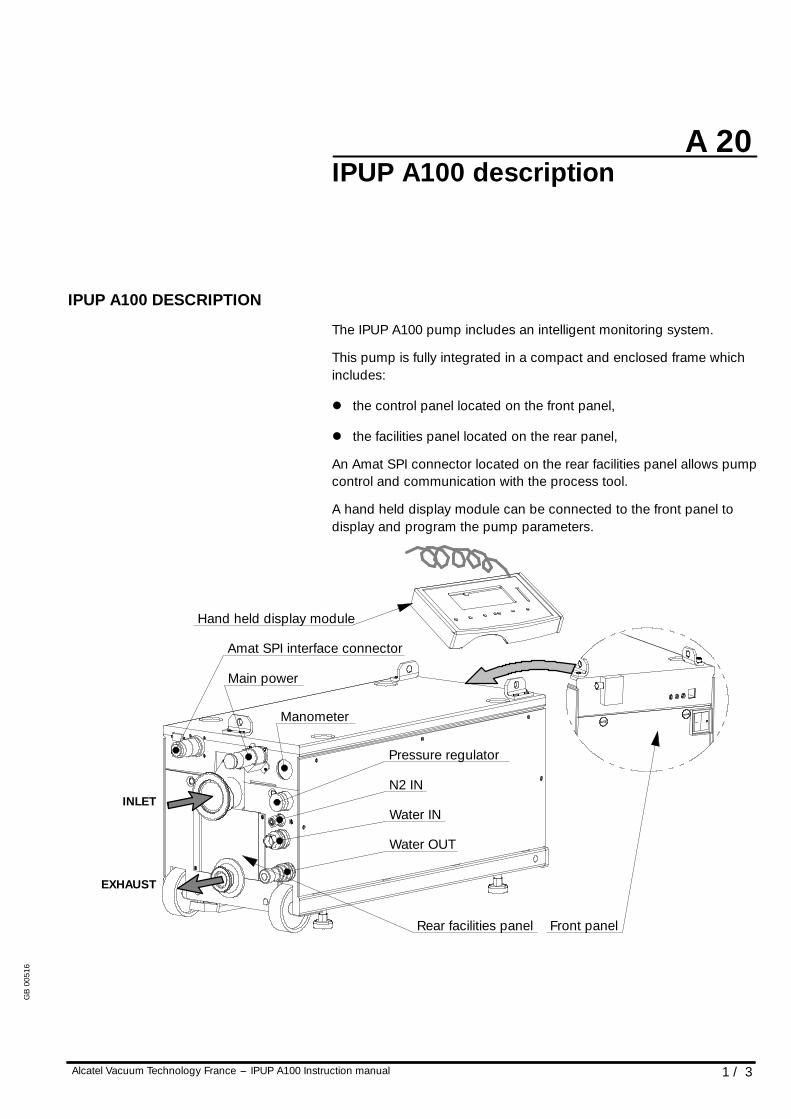
The IPUP A100 pump includes an intelligent monitoring system.
This pump is fully integrated in a compact and enclosed frame whichincludes:
l the control panel located on the front panel,
l the facilities panel located on the rear panel,
An Amat SPI connector located on the rear facilities panel allows pumpcontrol and communication with the process tool.
A hand held display module can be connected to the front panel todisplay and program the pump parameters.
EXHAUST
Rear facilities panel Front panel
Amat SPI interface connector
INLET
Hand held display module
Pressure regulator
N2 IN
Water IN
Water OUT
Main power
Manometer
GB
0051
6
A 20
2 / 3 Alcatel Vacuum Technology France --- IPUP A100 Instruction manual
IPUP A100 description
INTERNAL EQUIPMENT OF THEIPUP A100 PUMPS
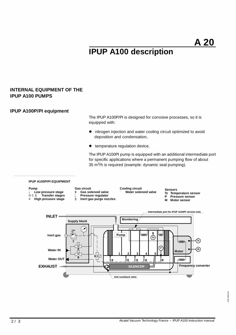
IPUP A100P/PI equipmentThe IPUP A100P/PI is designed for corrosive processes, so it isequipped with:
l nitrogen injection and water cooling circuit optimized to avoiddeposition and condensation,
l temperature regulation device.
The IPUP A100PI pump is equipped with an additional intermediate portfor specific applications where a permanent pumping flow of about35 m3/h is required (example: dynamic seal pumping).
P
IPUP A100P/PI EQUIPMENT
Pump¡ Low pressure stage©¢£ Transfer stages¤ High pressure stage
INLET
EXHAUST
Tc
M
21 3 4 56
9
9
7
Monitoring
Pump
Motor
Frequency converter
Anti suckback valve
Inert gas
Water IN
SILENCER
Supply block
Gas circuit¥ Gas solenoid valve¦ Pressure regulator§ Inert gas purge nozzles
Cooling circuit¨ Water solenoid valve
SensorsTc Temperature sensorP Pressure sensorM Motor sensor
Water OUT 88
Intermediate port for IPUP A100PI version only
Tc
8 8 8
GB
0051
6
A 20
3 / 3Alcatel Vacuum Technology France --- IPUP A100 Instruction manual
IPUP A100 description
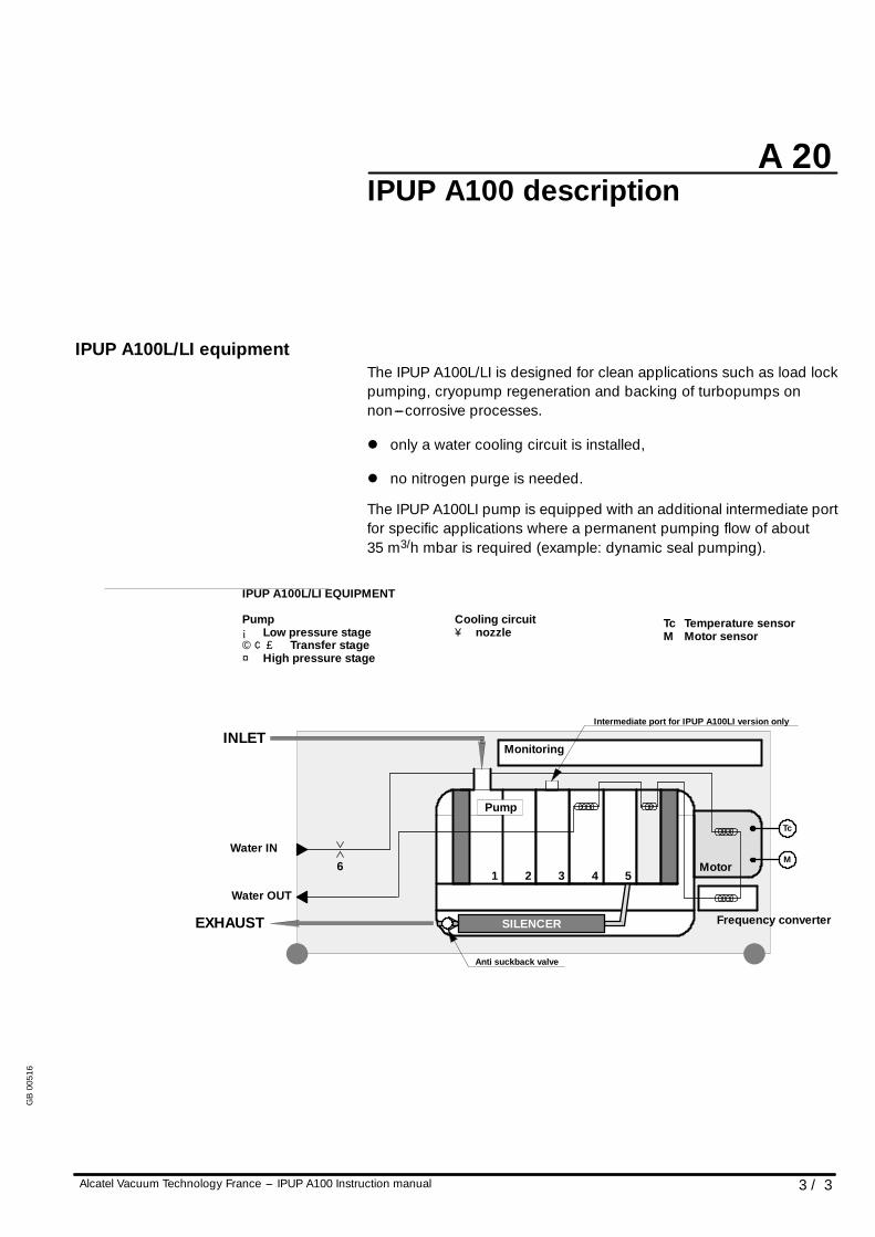
IPUP A100L/LI equipmentThe IPUP A100L/LI is designed for clean applications such as load lockpumping, cryopump regeneration and backing of turbopumps onnon---corrosive processes.
l only a water cooling circuit is installed,
l no nitrogen purge is needed.
The IPUP A100LI pump is equipped with an additional intermediate portfor specific applications where a permanent pumping flow of about35 m3/h mbar is required (example: dynamic seal pumping).
IPUP A100L/LI EQUIPMENT
Pump¡ Low pressure stage©¢£ Transfer stage¤ High pressure stage
EXHAUST
M
21 3 4 5
Monitoring
Motor
Frequency converter
Anti suckback valve
Water IN
Cooling circuit¥ nozzle
Tc Temperature sensorM Motor sensor
Water OUT
Pump
Intermediate port for IPUP A100LI version only
INLET
SILENCER
6
Tc
GB
0051
6
A 30
1 / 2Alcatel Vacuum Technology France --- IPUP A100 Instruction manual
IPUP A100 monitoring system
GENERAL
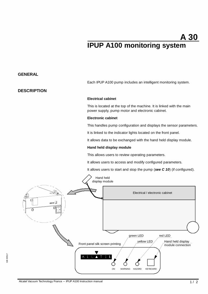
Each IPUP A100 pump includes an intelligent monitoring system.
DESCRIPTION
Electrical cabinet
This is located at the top of the machine. It is linked with the mainpower supply, pump motor and electronic cabinet.
Electronic cabinet
This handles pump configuration and displays the sensor parameters.
It is linked to the indicator lights located on the front panel.
It allows data to be exchanged with the hand held display module.
Hand held display module
This allows users to review operating parameters.
It allows users to access and modify configured parameters.
It allows users to start and stop the pump (see C 10) (if configured).
Electrical / electronic cabinet
Hand helddisplay module
ON WARNING HAZARD KEYBOARD
Hand held displaymodule connection
red LED
yellow LED
green LED
Front panel silk screen printing
GB
0051
7
A 30
Alcatel Vacuum Technology France --- IPUP A100 Instruction manual2 / 2
IPUP A100 monitoring system
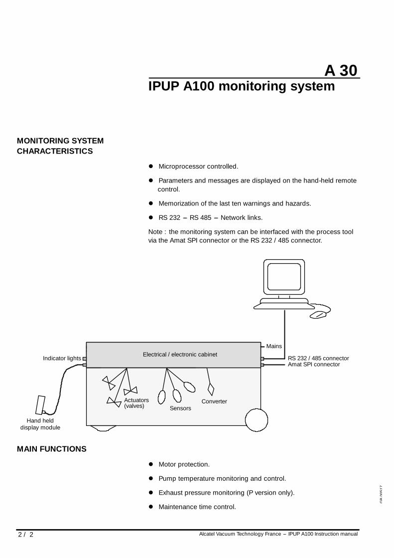
MONITORING SYSTEMCHARACTERISTICS
l Microprocessor controlled.
l Parameters and messages are displayed on the hand-held remotecontrol.
l Memorization of the last ten warnings and hazards.
l RS 232 --- RS 485 --- Network links.
Note : the monitoring system can be interfaced with the process toolvia the Amat SPI connector or the RS 232 / 485 connector.
Electrical / electronic cabinet
SensorsActuators(valves)
Indicator lights
Hand helddisplay module
Amat SPI connector
Mains
Converter
RS 232 / 485 connector
MAIN FUNCTIONS
l Motor protection.
l Pump temperature monitoring and control.
l Exhaust pressure monitoring (P version only).
l Maintenance time control.
GB
0051
7
A 40
Alcatel Vacuum Technology France --- IPUP A100 Instruction manual 1 / 9
IPUP A100 technical characteristics
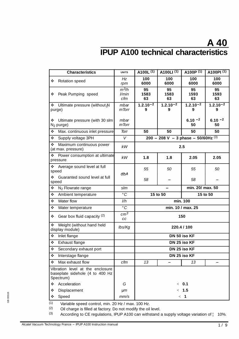
Characteristics UNITS A100L (1) A100LI (1) A100P (1) A100PI (1)
v Rotation speed Hzrpm
1006000
1006000
1006000
1006000
v Peak Pumping speedm3/hl/mincfm
951583
63
951583
63
951593
63
951593
63
v Ultimate pressure (without N2purge)
v Ultimate pressure (with 30 slmN2 purge)
mbarmTorr
mbarmTorr
1.2.10---2
91.2.10---2
91.2.10---2
9
6.10 ---2
50
1.2.10---2
9
6.10 ---2
50
v Max. continuous inlet pressure Torr 50 50 50 50
v Supply voltage 3PH V 200 -- 208 V -- 3 phase -- 50/60Hz (3)
v Maximum continuous power(at max. pressure) kW 2.5
v Power consumption at ultimatepressure kW 1.8 1.8 2.05 2.05
v Average sound level at fullspeed
dbA55 50 55 50speed
v Guaranted sound level at fullspeed
dbA58 --- 58 ---
v N 2 Flowrate range slm -- min. 20/ max. 50
v Ambient temperature ° C 15 to 50 15 to 50
v Water flow l/h min. 100
v Water temperature ° C min. 10 / max. 25
v Gear box fluid capacity (2) cm3
cc 150
v Weight (without hand helddisplay module) lbs/Kg 220.4 / 100
v Inlet flange DN 50 iso KF
v Exhaust flange DN 25 iso KF
v Secondary exhaust port DN 25 iso KF
v Interstage flange DN 25 iso KF
v Max exhaust flow cfm 13 --- 13 ---
Vibration level at the enclosurebaseplate sidehole (4 to 400 HzSpectrum)v Accelerationv Displacementv Speed
Gµm
mm/s
< 0.1< 1.5< 1
(1) Variable speed control, min. 20 Hz / max. 100 Hz.(2) Oil charge is filled at factory. Do not modify the oil level.(3) According to CE regulations, IPUP A100 can withstand a supply voltage variation of ¦ 10%.
GB
0051
8
A 40
2 / 9 Alcatel Vacuum Technology France --- IPUP A100 Instruction manual
IPUP A100 technical characteristics
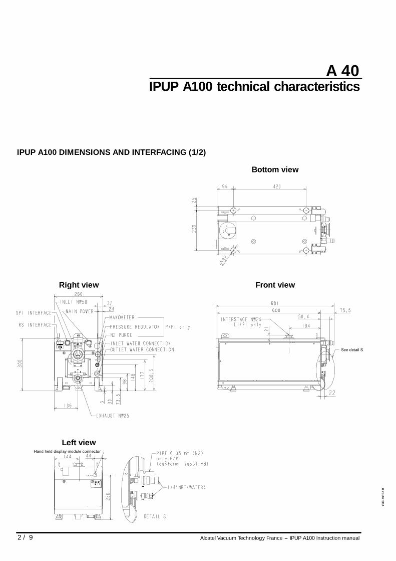
IPUP A100 DIMENSIONS AND INTERFACING (1/2)
Front view
Bottom view
Right view
Left viewHand held display module connector
See detail S
GB
0051
8
A 40
Alcatel Vacuum Technology France --- IPUP A100 Instruction manual 3 / 9
IPUP A100 technical characteristics
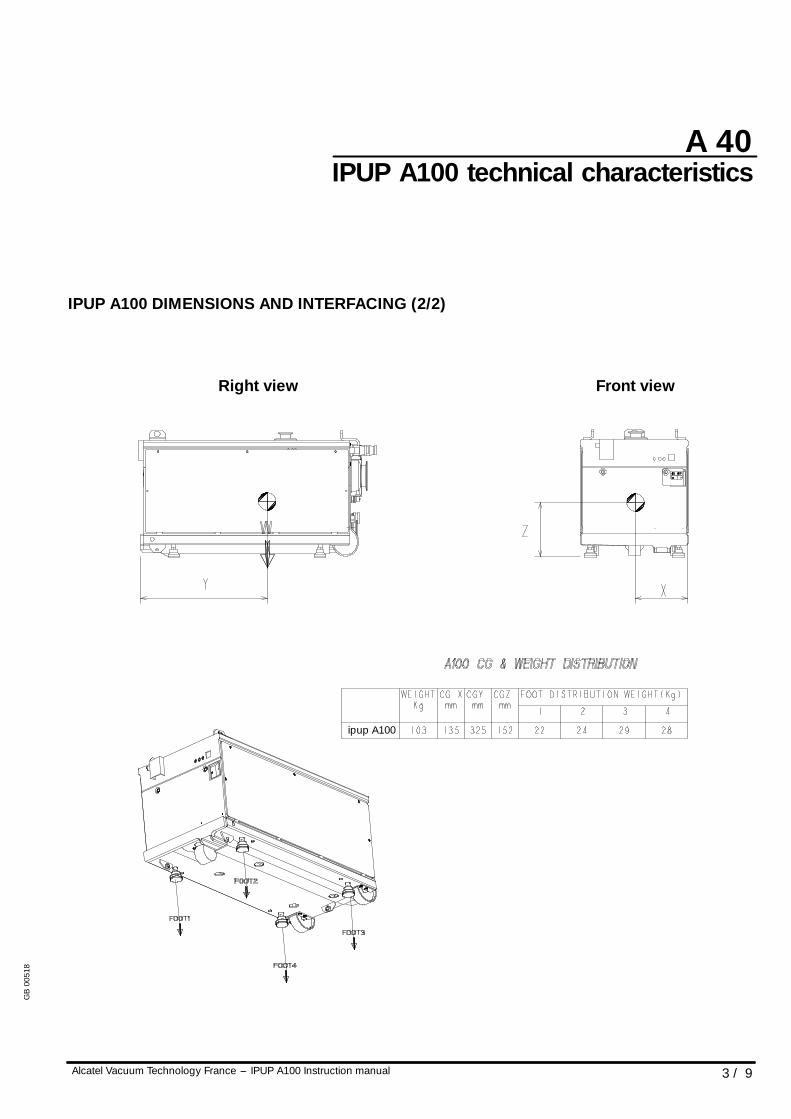
IPUP A100 DIMENSIONS AND INTERFACING (2/2)
Front viewRight view
ipup A100
GB
0051
8
A 40
4 / 9 Alcatel Vacuum Technology France --- IPUP A100 Instruction manual
IPUP A100 technical characteristics
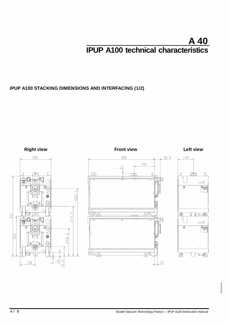
IPUP A100 STACKING DIMENSIONS AND INTERFACING (1/2)
Left viewFront viewRight view
GB
0051
8
A 40
Alcatel Vacuum Technology France --- IPUP A100 Instruction manual 5 / 9
IPUP A100 technical characteristics
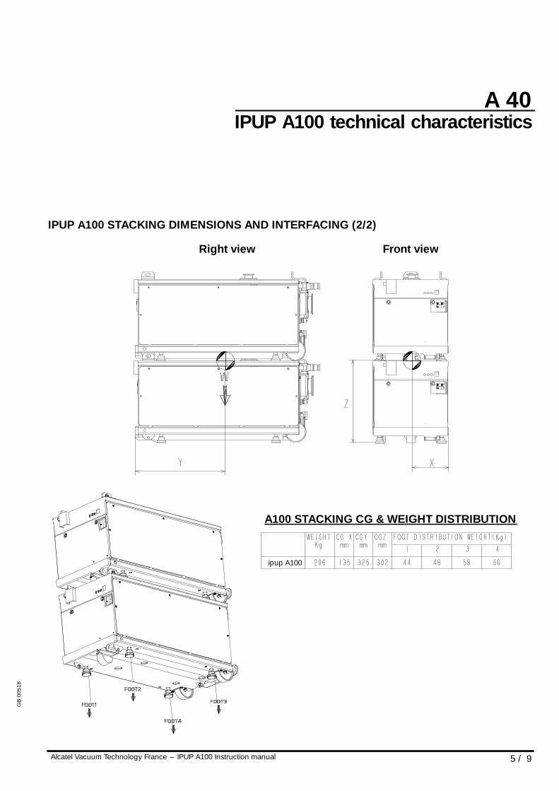
IPUP A100 STACKING DIMENSIONS AND INTERFACING (2/2)
Right view Front view
A100 STACKING CG & WEIGHT DISTRIBUTION
ipup A100
GB
0051
8
A 40
6 / 9 Alcatel Vacuum Technology France --- IPUP A100 Instruction manual
IPUP A100 technical characteristics
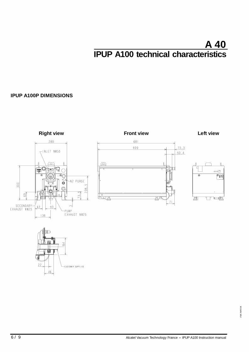
IPUP A100P DIMENSIONS
Front view Left viewRight view
GB
0051
8
A 40
Alcatel Vacuum Technology France --- IPUP A100 Instruction manual 7 / 9
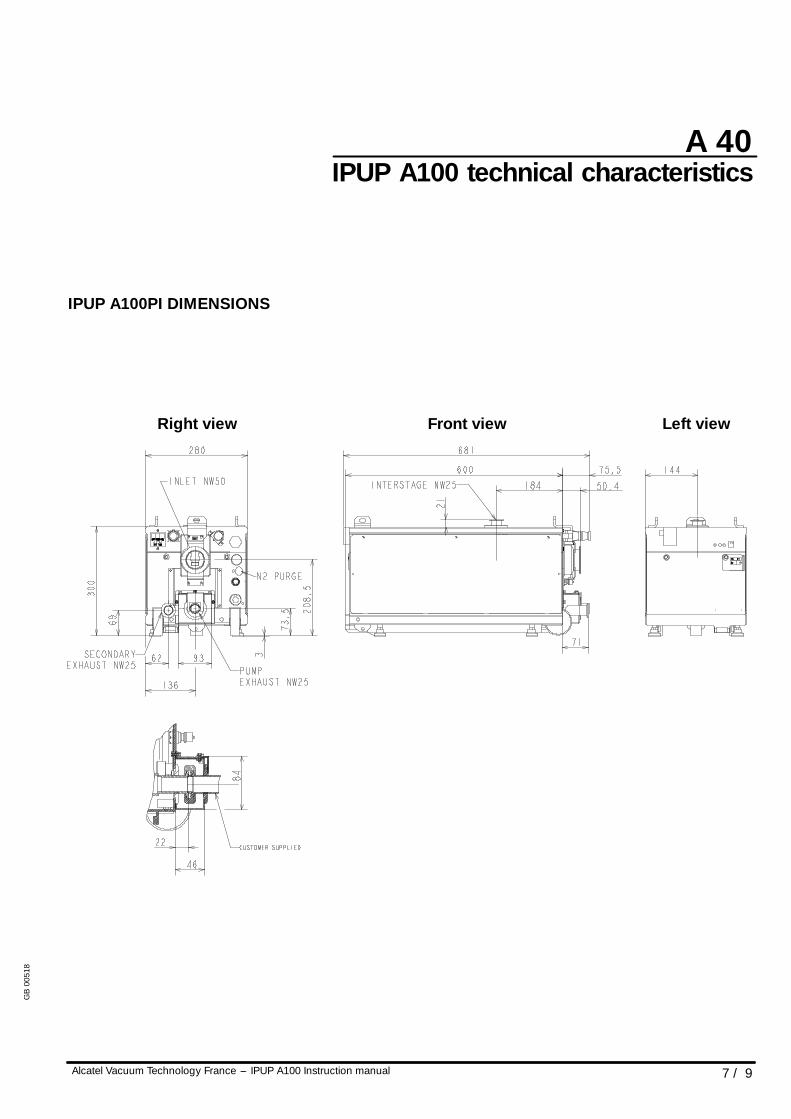
IPUP A100 technical characteristics
IPUP A100PI DIMENSIONS
Front view Left viewRight view
GB
0051
8
A 40
8 / 9 Alcatel Vacuum Technology France --- IPUP A100 Instruction manual
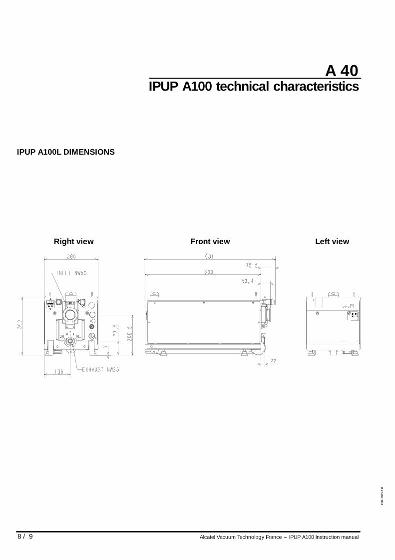
IPUP A100 technical characteristics
IPUP A100L DIMENSIONS
Front view Left viewRight view
GB
0051
8
A 40
Alcatel Vacuum Technology France --- IPUP A100 Instruction manual 9 / 9
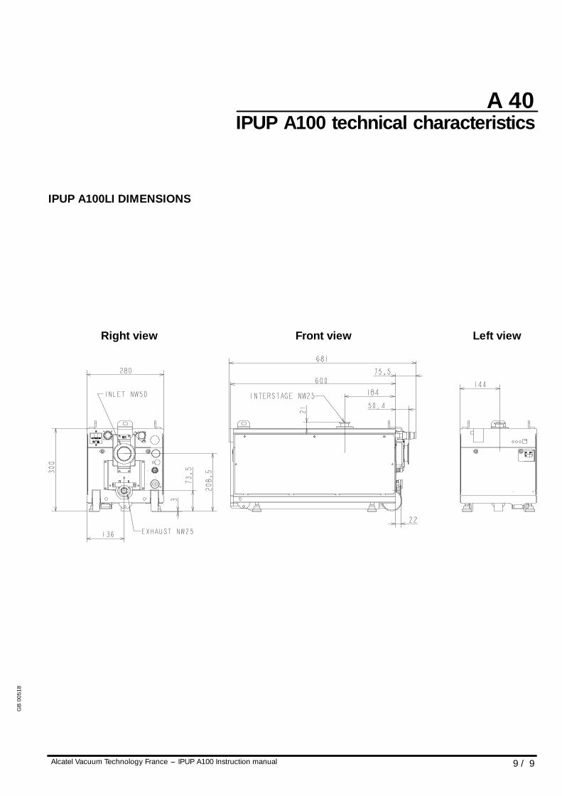
IPUP A100 technical characteristics
IPUP A100LI DIMENSIONS
Front view Left viewRight view
GB
0051
8
A 50
Alcatel Vacuum Technology France --- IPUP A100 Instruction manual 1 / 1
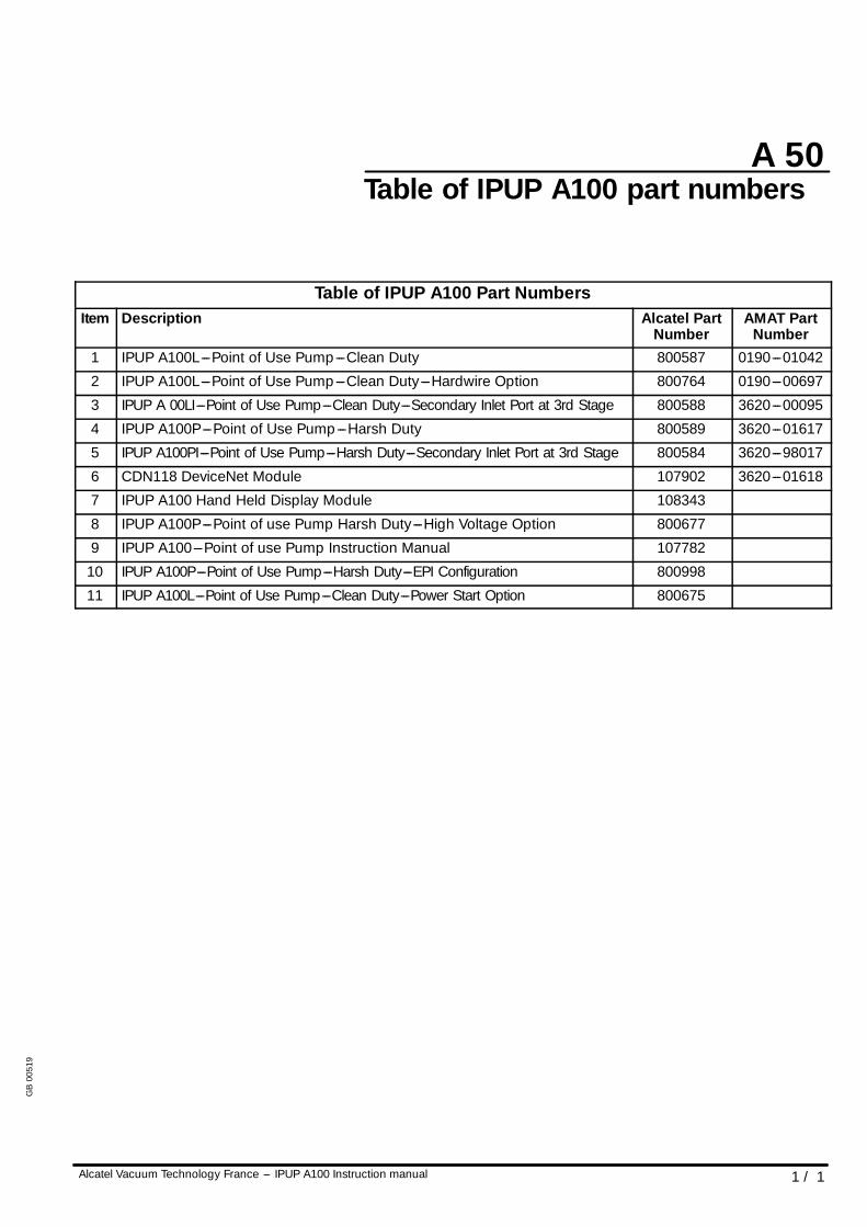
Table of IPUP A100 part numbers
Table of IPUP A100 Part NumbersItem Description Alcatel Part
NumberAMAT Part
Number1 IPUP A100L---Point of Use Pump---Clean Duty 800587 0190---01042
2 IPUP A100L---Point of Use Pump---Clean Duty---Hardwire Option 800764 0190---00697
3 IPUP A 00LI---Point of Use Pump---Clean Duty---Secondary Inlet Port at 3rd Stage 800588 3620---00095
4 IPUP A100P---Point of Use Pump---Harsh Duty 800589 3620---01617
5 IPUP A100PI---Point of Use Pump---Harsh Duty---Secondary Inlet Port at 3rd Stage 800584 3620---98017
6 CDN118 DeviceNet Module 107902 3620---01618
7 IPUP A100 Hand Held Display Module 108343
8 IPUP A100P---Point of use Pump Harsh Duty---High Voltage Option 800677
9 IPUP A100---Point of use Pump Instruction Manual 107782
10 IPUP A100P---Point of Use Pump---Harsh Duty---EPI Configuration 800998
11 IPUP A100L---Point of Use Pump---Clean Duty---Power Start Option 800675
GB
0051
9
A 60
Alcatel Vacuum Technology France --- IPUP A100 Instruction manual 1 / 1
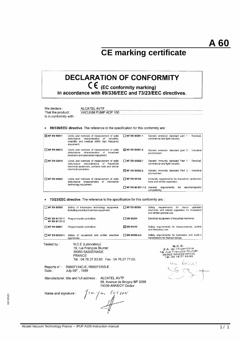
CE marking certificate
GB
0052
0
A 70
Alcatel Vacuum Technology France --- IPUP A100 Instruction manual 1 / 1
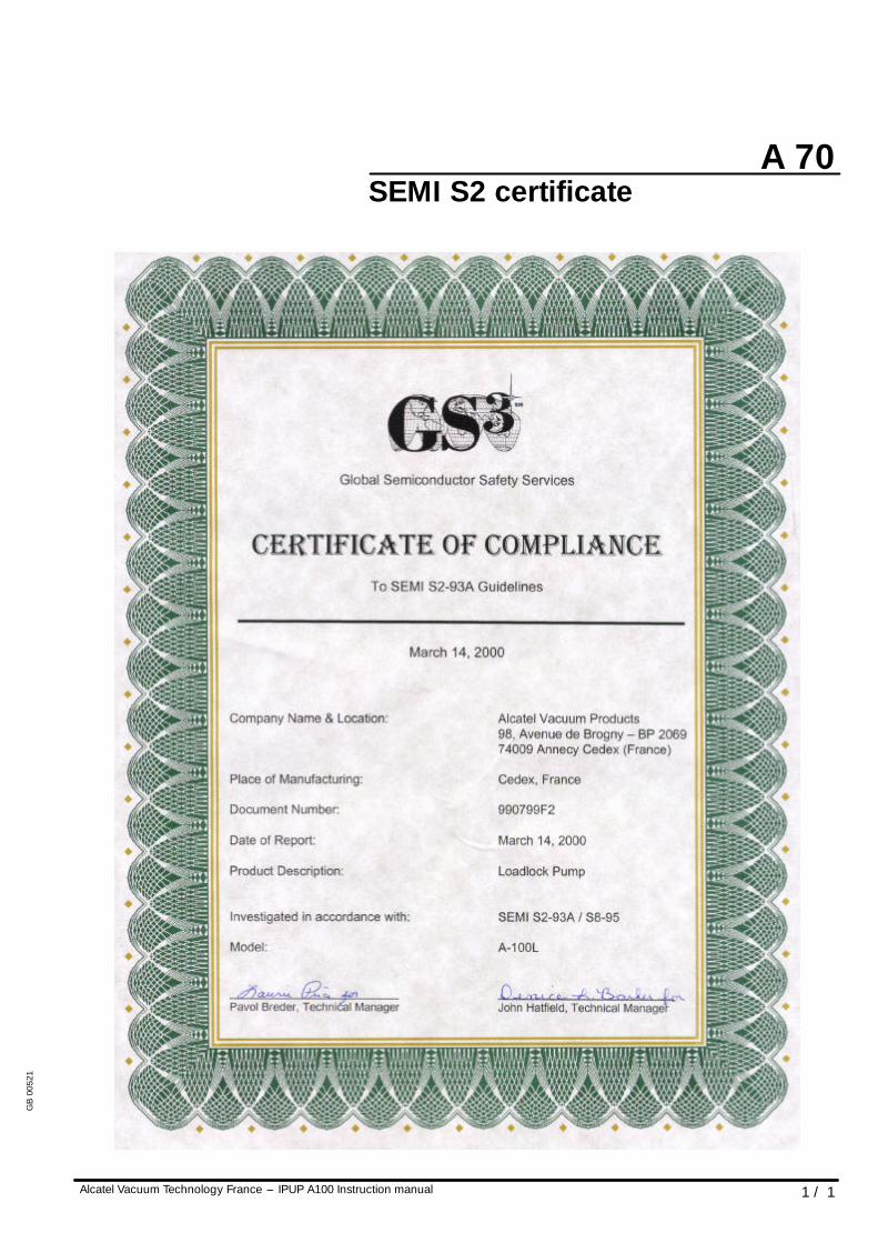
SEMI S2 certificate
GB
0052
1
Chapter B
Alcatel Vacuum Technology France --- IPUP A100 Instruction manual 1 / 1
IPUP A 100 instruction manual
Start upSafety instructions B 00. . . . . . . . . . . . . . . . . . . . . . . .
Unpacking / Handling / Storage B 10. . . . . . . . . . . . .
Positioning the pump in the pumping installation B 20
Connection to the cooling circuit B 30. . . . . . . . . . . . .
Inert gas purge connection (N2 connection) B 40. . . .
Electrical connection B 50. . . . . . . . . . . . . . . . . . . . . .
Amat smart pump interface connection B 60. . . . . . .
RS 232 or RS 485 link wiring B 70. . . . . . . . . . . . . . . .
Connection to the pumping circuit B 80. . . . . . . . . . .
GB
0052
2
WARNING
WARNING
B 00
1 / 4Alcatel Vacuum Technology France --- IPUP A100 Instruction manual
Safety instructions
GENERAL
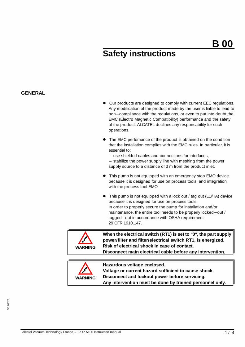
l Our products are designed to comply with current EEC regulations.Any modification of the product made by the user is liable to lead tonon---compliance with the regulations, or even to put into doubt theEMC (Electro Magnetic Compatibility) performance and the safetyof the product. ALCATEL declines any responsability for suchoperations.
l The EMC perfomance of the product is obtained on the conditionthat the installation complies with the EMC rules. In particular, it isessential to:--- use shielded cables and connections for interfaces,--- stabilize the power supply line with meshing from the powersupply source to a distance of 3 m from the product inlet.
l This pump is not equipped with an emergency stop EMO devicebecause it is designed for use on process tools and integrationwith the process tool EMO.
l This pump is not equipped with a lock out / tag out (LO/TA) devicebecause it is designed for use on process tools.In order to properly secure the pump for installation and/ormaintenance, the entire tool needs to be properly locked---out /tagged---out in accordance with OSHA requirement29 CFR.1910.147.
When the electrical switch (RT1) is set to “0“, the part supplypower/filter and filter/electrical switch RT1, is energized.Risk of electrical shock in case of contact.Disconnect main electrical cable before any intervention.
Hazardous voltage enclosed.Voltage or current hazard sufficient to cause shock.Disconnect and lockout power before servicing.Any intervention must be done by trained personnel only.
GB
0052
3
!WARNING
!WARNING
!WARNING
WARNING
B 00
Alcatel Vacuum Technology France --- IPUP A100 Instruction manual2 / 4
Safety instructions
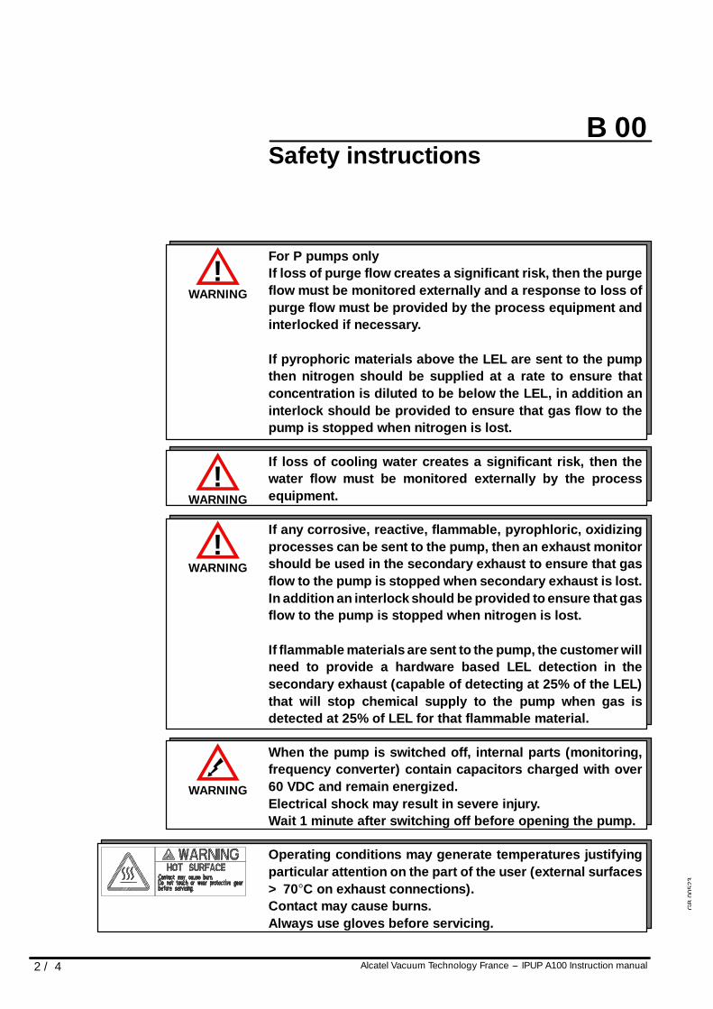
For P pumps onlyIf loss of purge flow creates a significant risk, then the purgeflow must be monitored externally and a response to loss ofpurge flow must be provided by the process equipment andinterlocked if necessary.
If pyrophoric materials above the LEL are sent to the pumpthen nitrogen should be supplied at a rate to ensure thatconcentration is diluted to be below the LEL, in addition aninterlock should be provided to ensure that gas flow to thepump is stopped when nitrogen is lost.
If loss of cooling water creates a significant risk, then thewater flow must be monitored externally by the processequipment.
If any corrosive, reactive, flammable, pyrophloric, oxidizingprocesses can be sent to the pump, then an exhaust monitorshould be used in the secondary exhaust to ensure that gasflow to the pump is stopped when secondary exhaust is lost.In addition an interlock should be provided to ensure that gasflow to the pump is stopped when nitrogen is lost.
If flammable materials are sent to the pump, the customer willneed to provide a hardware based LEL detection in thesecondary exhaust (capable of detecting at 25% of the LEL)that will stop chemical supply to the pump when gas isdetected at 25% of LEL for that flammable material.
When the pump is switched off, internal parts (monitoring,frequency converter) contain capacitors charged with over60 VDC and remain energized.Electrical shock may result in severe injury.Wait 1 minute after switching off before opening the pump.
Operating conditions may generate temperatures justifyingparticular attention on the part of the user (external surfaces> 70°C on exhaust connections).Contact may cause burns.Always use gloves before servicing.
GB
0052
3
!WARNING
B 00
3 / 4Alcatel Vacuum Technology France --- IPUP A100 Instruction manual
Safety instructions
l Alcatel has no control over the types of gases passing through thispump. Frequently, process gases are toxic, flammable, corrosive,explosive or otherwise reactive. Since these gases can causeserious injury or death, it is very important to plumb the exhaust ofthe pump to the facility’s hazardous gas exhaust system whichincorporates appropriate filters, scrubbers, etc., to insure that theexhaust meets all air regulations.
l Check that pump is correctly connected to the equipment(see B 50).
Safety interlockThe pump motor is protected against overload through thedrive ”start/stop” and enable control circuitry of the variablespeed controller. The drive start/stop includes solid statecomponents. If hazards due to accidental contact withmoving machinery or unintentional flow or liquid, gas orsolids exist, an additional hardwired stop circuit is requiredto remove AC input power to the drive.This interlock must never be overridden during installation,use or maintenance.Once activated power will be switch off and the pump will beput in a safe condition. When a fault occurs, the cause must becorrected before the fault can be cleared. It is required toswitch power off and on to clear the fault.
GB
0052
3
B 00
Alcatel Vacuum Technology France --- IPUP A100 Instruction manual4 / 4
Safety instructions
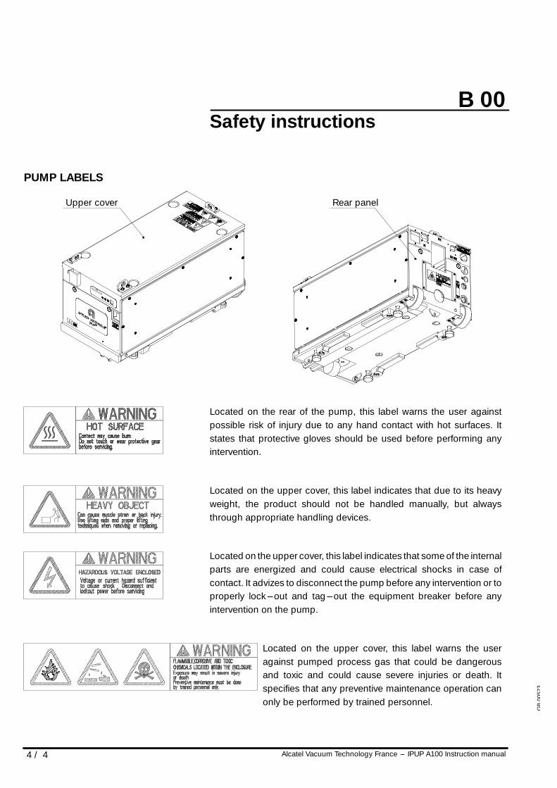
PUMP LABELS
Upper cover Rear panel
Located on the rear of the pump, this label warns the user againstpossible risk of injury due to any hand contact with hot surfaces. Itstates that protective gloves should be used before performing anyintervention.
Located on the upper cover, this label indicates that due to its heavyweight, the product should not be handled manually, but alwaysthrough appropriate handling devices.
Located on the upper cover, this label indicates that some of the internalparts are energized and could cause electrical shocks in case ofcontact. It advizes to disconnect the pump before any intervention or toproperly lock---out and tag---out the equipment breaker before anyintervention on the pump.
Located on the upper cover, this label warns the useragainst pumped process gas that could be dangerousand toxic and could cause severe injuries or death. Itspecifies that any preventive maintenance operation canonly be performed by trained personnel.
GB
0052
3
A
c
B
B 10
1 / 6Alcatel Vacuum Technology France --- IPUP A100 Instruction manual
Unpacking / Handling / Storage
PRECAUTIONS
l If the equipment has been damaged, take necessary steps with thecarrier and inform Alcatel, if necessary. In all cases, Alcatelrecommends that the packaging be kept, in the event that theequipment needs to be transported or put into prolonged storage.
l Risk of tilting: compliance with the EEC safety rules is guaranteed(normal range ± 10°). However, precautions should be taken againstthe risk of tilting during product handling, installation and operation.
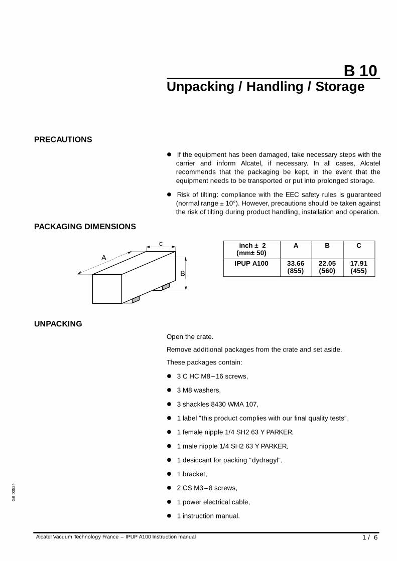
PACKAGING DIMENSIONS
inch ± 2(mm±50)
A B C
IPUP A100 33.66(855)
22.05(560)
17.91(455)
UNPACKINGOpen the crate.
Remove additional packages from the crate and set aside.
These packages contain:
l 3 C HC M8---16 screws,
l 3 M8 washers,
l 3 shackles 8430 WMA 107,
l 1 label ”this product complies with our final quality tests”,
l 1 female nipple 1/4 SH2 63 Y PARKER,
l 1 male nipple 1/4 SH2 63 Y PARKER,
l 1 desiccant for packing “dydragyl”,
l 1 bracket,
l 2 CS M3---8 screws,
l 1 power electrical cable,
l 1 instruction manual.
GB
0052
4
B 10
2 / 6 Alcatel Vacuum Technology France --- IPUP A100 Instruction manual
Unpacking / Handling / Storage
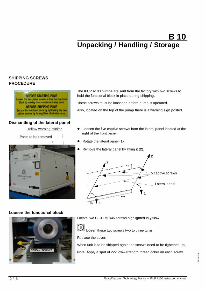
SHIPPING SCREWSPROCEDURE
The IPUP A100 pumps are sent from the factory with two screws tohold the functional block in place during shipping.
These screws must be loosened before pump is operated.
Also, located on the top of the pump there is a warning sign posted.
Dismantling of the lateral panell Loosen the five captive screws from the lateral panel located at the
right of the front panel.
l Rotate the lateral panel (1).
l Remove the lateral panel by lifting it (2).
5 captive screws
Lateral panel
1
2
2
1
Loosen the functional blockLocate two C CH M8x45 screws highlighted in yellow.
6loosen these two screws two to three turns.
Replace the cover.
When unit is to be shipped again the screws need to be tightened up.
Note: Apply a spot of 222 low---strength threadlocker on each screw.
Yellow warning sticker
Panel to be removed
Yellow screws
GB
0052
4
B 10
3 / 6Alcatel Vacuum Technology France --- IPUP A100 Instruction manual
Unpacking / Handling / Storage
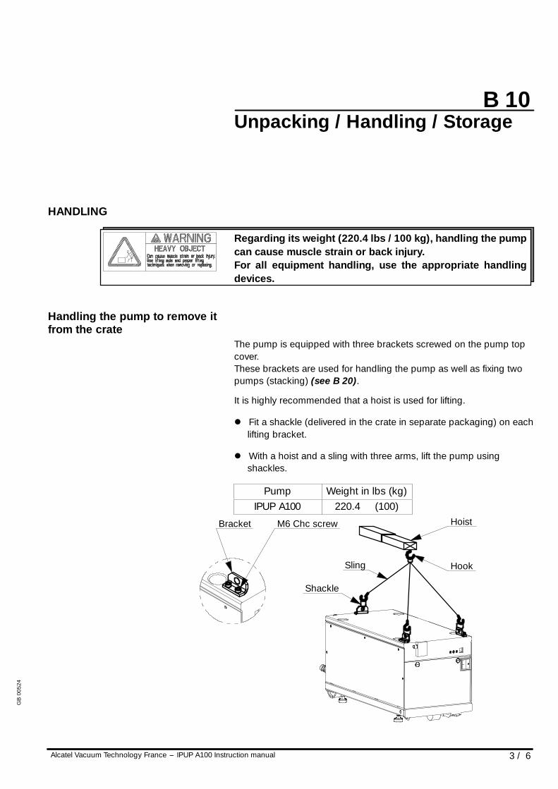
HANDLING
Regarding its weight (220.4 lbs / 100 kg), handling the pumpcan cause muscle strain or back injury.For all equipment handling, use the appropriate handlingdevices.
Handling the pump to remove itfrom the crate
The pump is equipped with three brackets screwed on the pump topcover.These brackets are used for handling the pump as well as fixing twopumps (stacking) (see B 20).
It is highly recommended that a hoist is used for lifting.
l Fit a shackle (delivered in the crate in separate packaging) on eachlifting bracket.
l With a hoist and a sling with three arms, lift the pump usingshackles.
Pump Weight in lbs (kg)IPUP A100 220.4 (100)
Bracket M6 Chc screw Hoist
Hook
Shackle
Sling
GB
0052
4
B 10
4 / 6 Alcatel Vacuum Technology France --- IPUP A100 Instruction manual
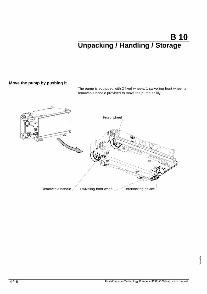
Unpacking / Handling / Storage
Move the pump by pushing itThe pump is equipped with 2 fixed wheels, 1 swivelling front wheel, aremovable handle provided to move the pump easily.
Fixed wheel
Swiveling front wheelRemovable handle Interlocking device
GB
0052
4
B 10
5 / 6Alcatel Vacuum Technology France --- IPUP A100 Instruction manual
Unpacking / Handling / Storage
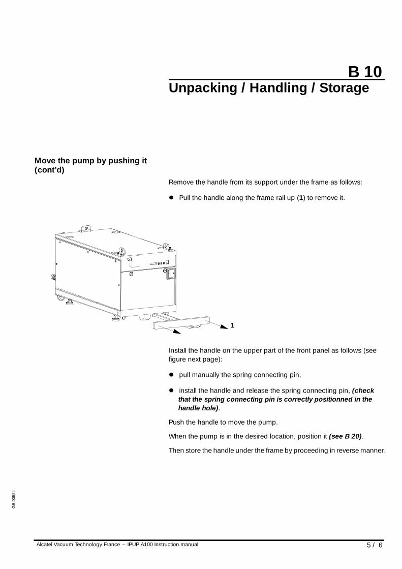
Move the pump by pushing it(cont’d)
Remove the handle from its support under the frame as follows:
l Pull the handle along the frame rail up (1) to remove it.
1
Install the handle on the upper part of the front panel as follows (seefigure next page):
l pull manually the spring connecting pin,
l install the handle and release the spring connecting pin, (checkthat the spring connecting pin is correctly positionned in thehandle hole).
Push the handle to move the pump.
When the pump is in the desired location, position it (see B 20).
Then store the handle under the frame by proceeding in reverse manner.
GB
0052
4
B 10
6 / 6 Alcatel Vacuum Technology France --- IPUP A100 Instruction manual
Unpacking / Handling / Storage
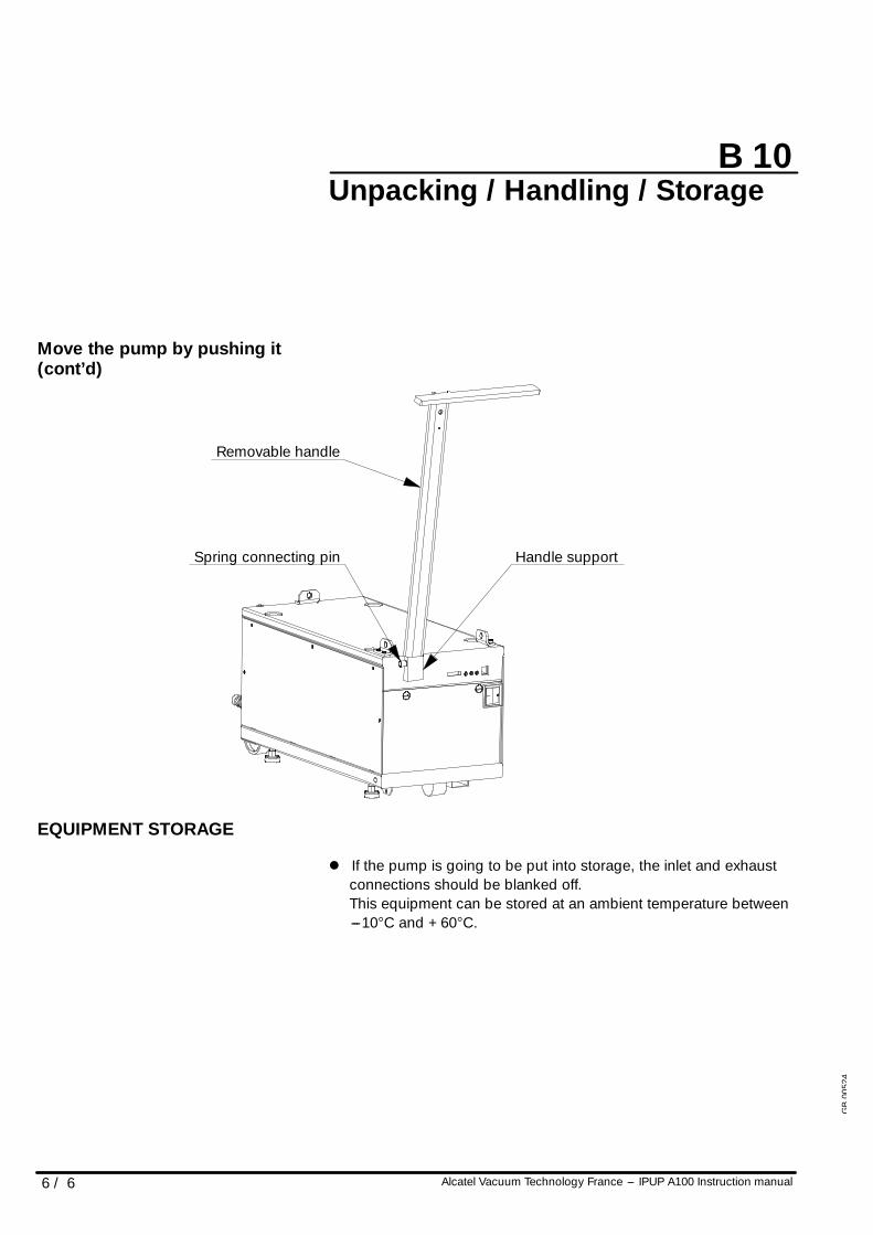
Move the pump by pushing it(cont’d)
Removable handle
Spring connecting pin Handle support
EQUIPMENT STORAGE
l If the pump is going to be put into storage, the inlet and exhaustconnections should be blanked off.This equipment can be stored at an ambient temperature between---10°C and +60°C.
GB
0052
4
B 20
1 / 3Alcatel Vacuum Technology France --- IPUP A100 Instruction manual
Positioning the pump in thepumping installation
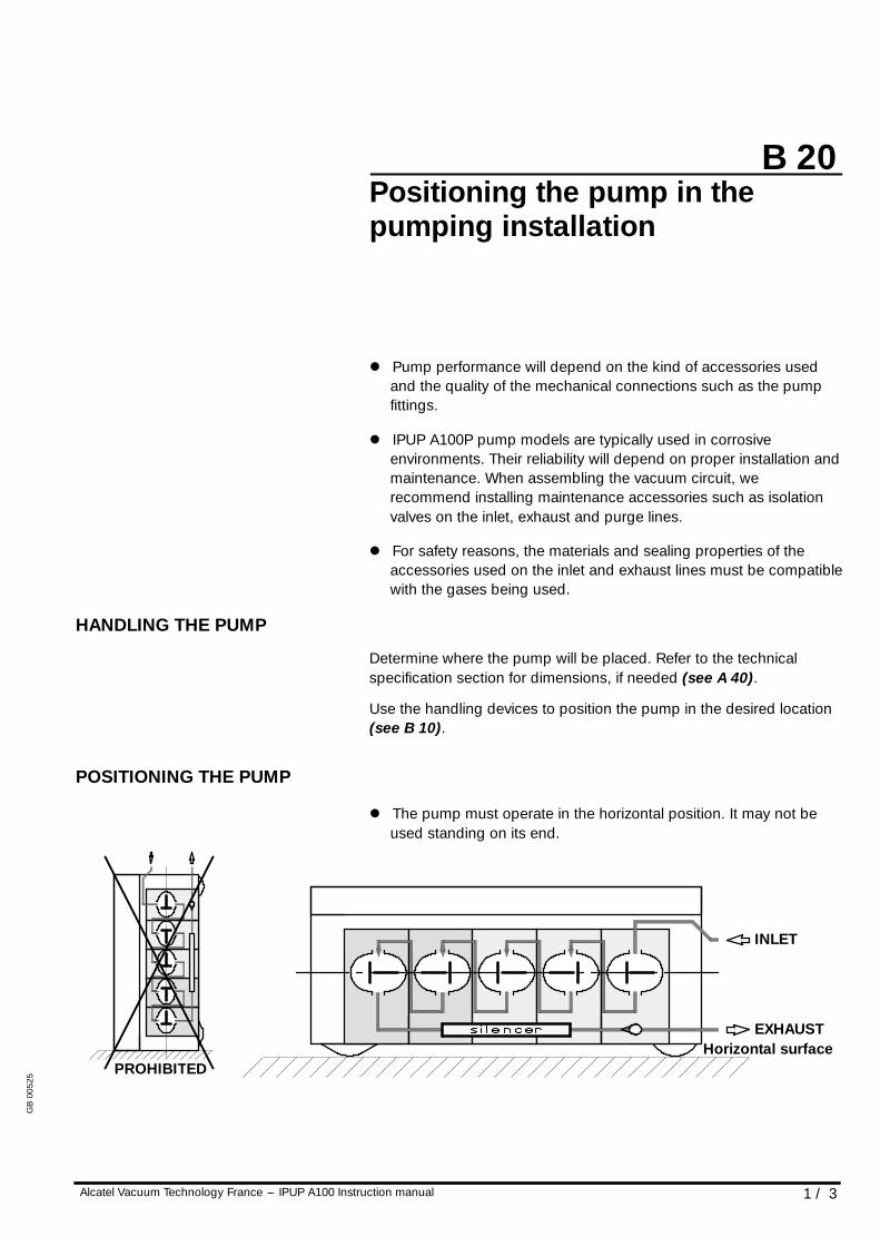
l Pump performance will depend on the kind of accessories usedand the quality of the mechanical connections such as the pumpfittings.
l IPUP A100P pump models are typically used in corrosiveenvironments. Their reliability will depend on proper installation andmaintenance. When assembling the vacuum circuit, werecommend installing maintenance accessories such as isolationvalves on the inlet, exhaust and purge lines.
l For safety reasons, the materials and sealing properties of theaccessories used on the inlet and exhaust lines must be compatiblewith the gases being used.
HANDLING THE PUMP
Determine where the pump will be placed. Refer to the technicalspecification section for dimensions, if needed (see A 40).
Use the handling devices to position the pump in the desired location(see B 10).
POSITIONING THE PUMP
l The pump must operate in the horizontal position. It may not beused standing on its end.
EXHAUST
INLET
PROHIBITEDHorizontal surface
GB
0052
5
B 20
2 / 3 Alcatel Vacuum Technology France --- IPUP A100 Instruction manual
Positioning the pump in thepumping installation
POSITIONING THE PUMP(CONT’D)
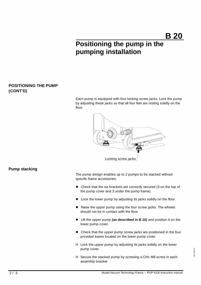
Each pump is equipped with four locking screw jacks. Lock the pumpby adjusting these jacks so that all four feet are resting solidly on thefloor.
Locking screw jacks
Pump stackingThe pump design enables up to 2 pumps to be stacked withoutspecific frame accessories.
l Check that the six brackets are correctly secured (3 on the top ofthe pump cover and 3 under the pump frame).
l Lock the lower pump by adjusting its jacks solidly on the floor.
l Raise the upper pump using the four screw jacks. The wheelsshould not be in contact with the floor.
l Lift the upper pump (as described in B 10) and position it on thelower pump cover.
l Check that the upper pump screw jacks are positioned in the fourprovided bases located on the lower pump cover.
H Lock the upper pump by adjusting its jacks solidly on the lowerpump cover.
H Secure the stacked pump by screwing a CHc M8 screw in eachassembly bracket
GB
0052
5
B 20
3 / 3Alcatel Vacuum Technology France --- IPUP A100 Instruction manual
Positioning the pump in thepumping installation
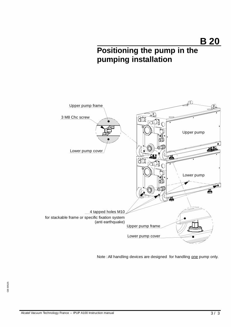
Upper pump frame
Lower pump cover
4 tapped holes M10for stackable frame or specific fixation system
(anti earthquake)
3 M8 Chc screw
Lower pump
Upper pump
Upper pump frame
Lower pump cover
Note :All handling devices are designed for handling one pump only.
GB
0052
5
B 30
1 / 2Alcatel Vacuum Technology France --- IPUP A100 Instruction manual
Connection to the cooling circuit
WATER CHARACTERISTICS
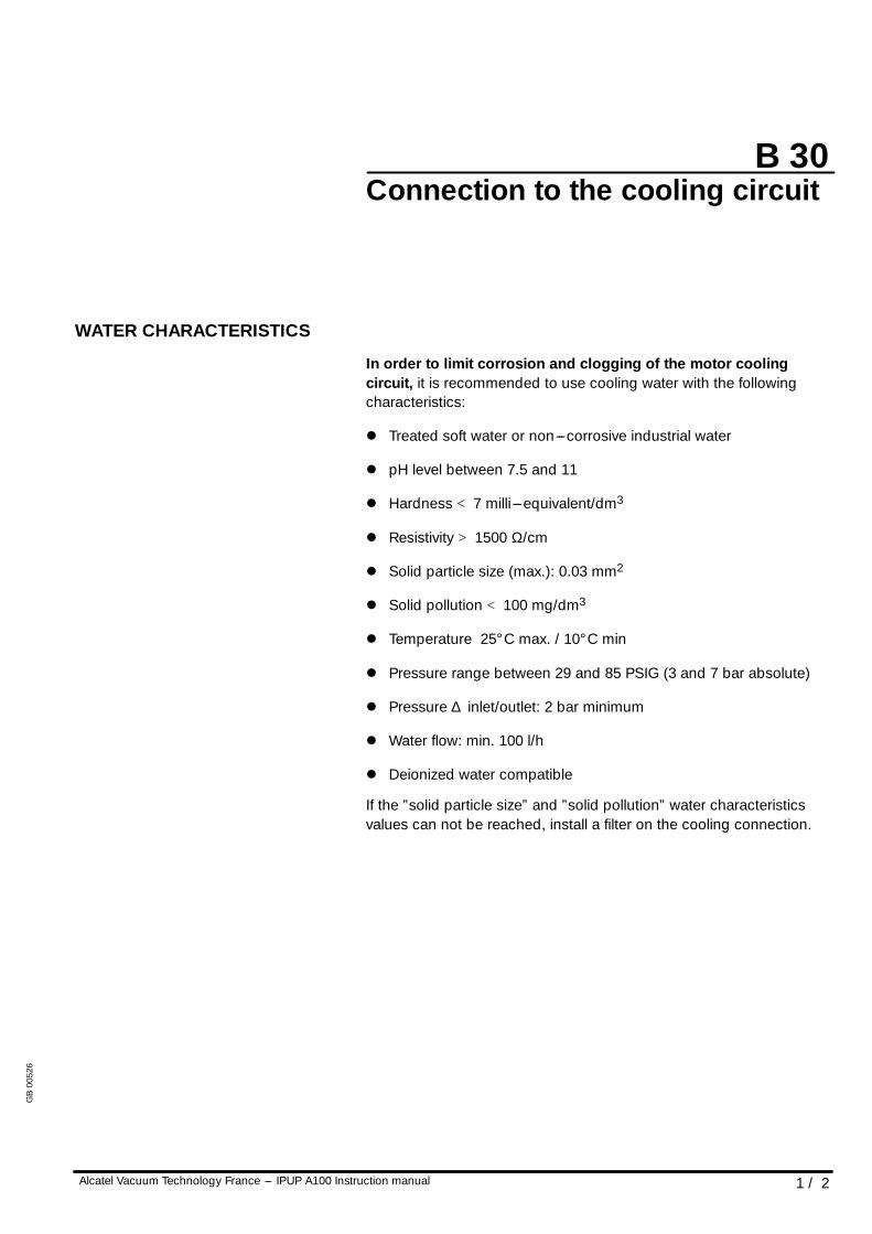
In order to limit corrosion and clogging of the motor coolingcircuit, it is recommended to use cooling water with the followingcharacteristics:
l Treated soft water or non---corrosive industrial water
l pH level between 7.5 and 11
l Hardness < 7 milli ---equivalent/dm3
l Resistivity > 1500 Ω/cm
l Solid particle size (max.): 0.03 mm2
l Solid pollution < 100 mg/dm3
l Temperature 25° C max. / 10° C min
l Pressure range between 29 and 85 PSIG (3 and 7 bar absolute)
l Pressure ∆ inlet/outlet: 2 bar minimum
l Water flow: min. 100 l/h
l Deionized water compatible
If the ”solid particle size” and ”solid pollution” water characteristicsvalues can not be reached, install a filter on the cooling connection.
GB
0052
6
B 30
2 / 2 Alcatel Vacuum Technology France --- IPUP A100 Instruction manual
Connection to the cooling circuit
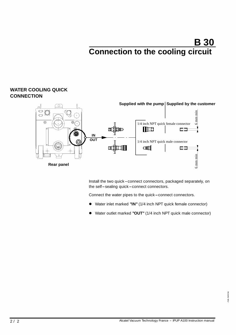
WATER COOLING QUICKCONNECTION
Rear panel
Supplied with the pump
1/4 inch NPT quick female connector
1/4 inch NPT quick male connectorOUTIN
6m
mm
in6
mm
min
Supplied by the customer
Install the two quick---connect connectors, packaged separately, onthe self---sealing quick---connect connectors.
Connect the water pipes to the quick---connect connectors.
l Water inlet marked ”IN” (1/4 inch NPT quick female connector)
l Water outlet marked ”OUT” (1/4 inch NPT quick male connector)
GB
0052
6
CAUTION!
B 40
Alcatel Vacuum Technology France --- IPUP A100 Instruction manual 1 / 2
Inert gas purge connection(N2 connection)
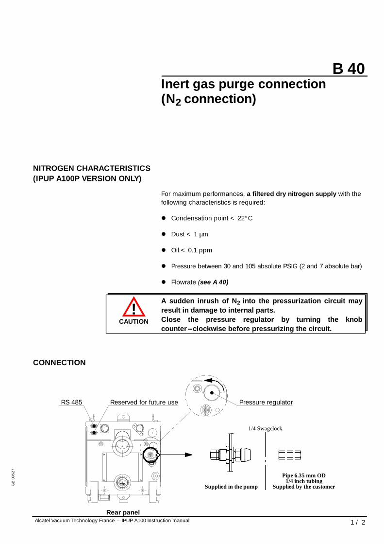
NITROGEN CHARACTERISTICS(IPUP A100P VERSION ONLY)
For maximum performances, a filtered dry nitrogen supply with thefollowing characteristics is required:
l Condensation point < 22° C
l Dust < 1 µm
l Oil < 0.1 ppm
l Pressure between 30 and 105 absolute PSIG (2 and 7 absolute bar)
l Flowrate (see A 40)
A sudden inrush of N2 into the pressurization circuit mayresult in damage to internal parts.Close the pressure regulator by turning the knobcounter--clockwise before pressurizing the circuit.
CONNECTION
1/4 Swagelock
Pipe 6.35 mm OD
Supplied in the pump
Rear panel
Pressure regulatorReserved for future useRS 485
1/4 inch tubingSupplied by the customerG
B00
527
B 40
2 / 2 Alcatel Vacuum Technology France --- IPUP A100 Instruction manual
Inert gas purge connection(N2 connection)
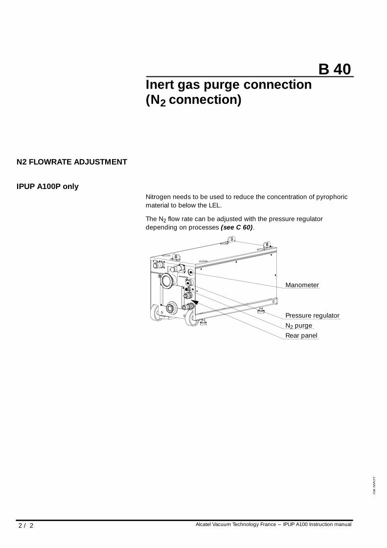
N2 FLOWRATE ADJUSTMENT
IPUP A100P onlyNitrogen needs to be used to reduce the concentration of pyrophoricmaterial to below the LEL.
The N2 flow rate can be adjusted with the pressure regulatordepending on processes (see C 60).
Rear panelN2 purgePressure regulator
Manometer
GB
0052
7
WARNING
WARNING
B 50
Alcatel Vacuum Technology France --- IPUP A100 Instruction manual 1 / 2
Electrical connection
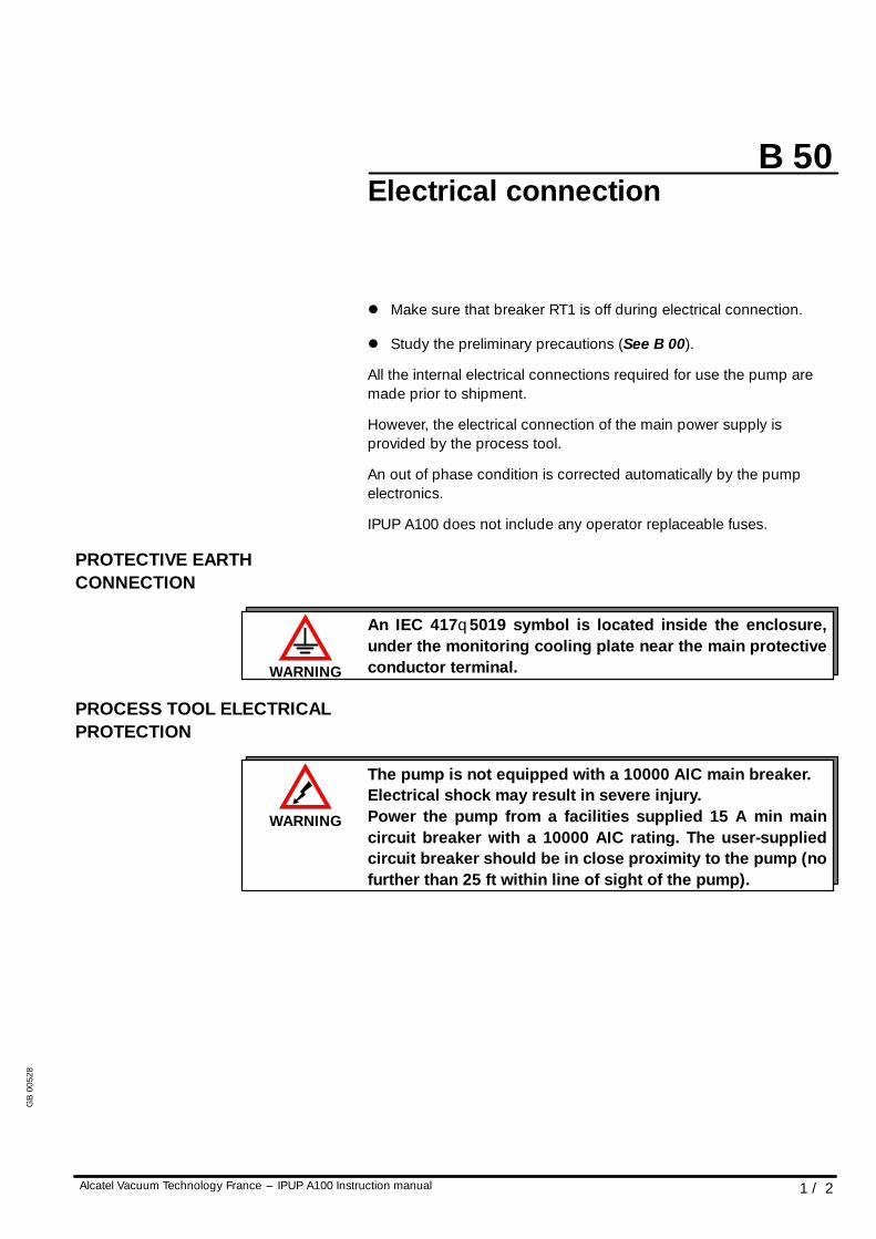
l Make sure that breaker RT1 is off during electrical connection.
l Study the preliminary precautions (See B 00).
All the internal electrical connections required for use the pump aremade prior to shipment.
However, the electrical connection of the main power supply isprovided by the process tool.
An out of phase condition is corrected automatically by the pumpelectronics.
IPUP A100 does not include any operator replaceable fuses.
PROTECTIVE EARTHCONNECTION
An IEC 417q5019 symbol is located inside the enclosure,under the monitoring cooling plate near the main protectiveconductor terminal.
PROCESS TOOL ELECTRICALPROTECTION
The pump is not equipped with a 10000 AIC main breaker.Electrical shock may result in severe injury.Power the pump from a facilities supplied 15 A min maincircuit breaker with a 10000 AIC rating. The user-suppliedcircuit breaker should be in close proximity to the pump (nofurther than 25 ft within line of sight of the pump).
GB
0052
8
B 50
2 / 2 Alcatel Vacuum Technology France --- IPUP A100 Instruction manual
Electrical connection
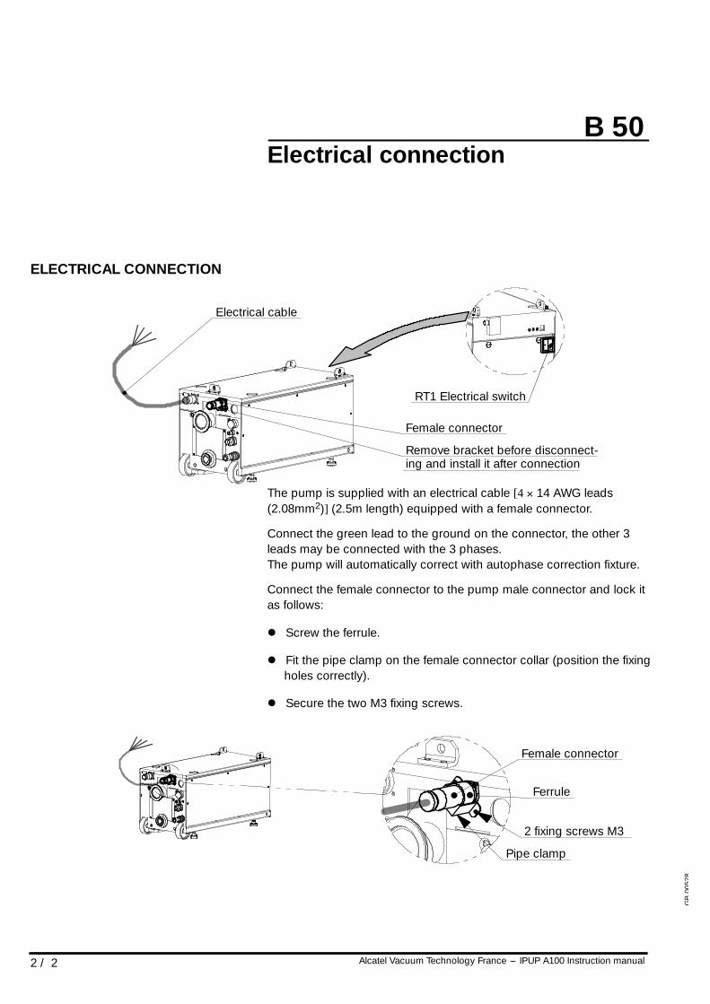
ELECTRICAL CONNECTION
Electrical cable
RT1 Electrical switch
Female connector
Remove bracket before disconnect-ing and install it after connection
The pump is supplied with an electrical cable [4 × 14 AWG leads(2.08mm2)] (2.5m length) equipped with a female connector.
Connect the green lead to the ground on the connector, the other 3leads may be connected with the 3 phases.The pump will automatically correct with autophase correction fixture.
Connect the female connector to the pump male connector and lock itas follows:
l Screw the ferrule.
l Fit the pipe clamp on the female connector collar (position the fixingholes correctly).
l Secure the two M3 fixing screws.
2 fixing screws M3
Pipe clamp
Female connector
Ferrule
GB
0052
8
CAUTION!
B 60
1 / 5Alcatel Vacuum Technology France --- IPUP A100 Instruction manual
Amat smart pump interfaceconnection
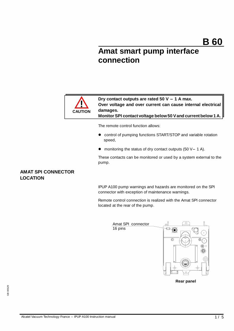
Dry contact outputs are rated 50 V -- 1 A max.Over voltage and over current can cause internal electricaldamages.Monitor SPI contact voltage below 50 V and current below 1 A.
The remote control function allows:
l control of pumping functions START/STOP and variable rotationspeed,
l monitoring the status of dry contact outputs (50 V--- 1 A).
These contacts can be monitored or used by a system external to thepump.
AMAT SPI CONNECTORLOCATION
IPUP A100 pump warnings and hazards are monitored on the SPIconnector with exception of maintenance warnings.
Remote control connection is realized with the Amat SPI connectorlocated at the rear of the pump.
Rear panel
Amat SPI connector16 pins
GB
0052
9
B 60
2 / 5 Alcatel Vacuum Technology France --- IPUP A100 Instruction manual
Amat smart pump interfaceconnection
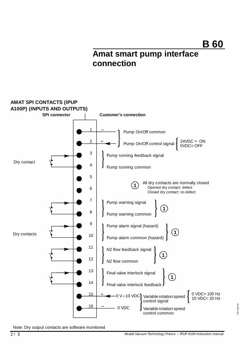
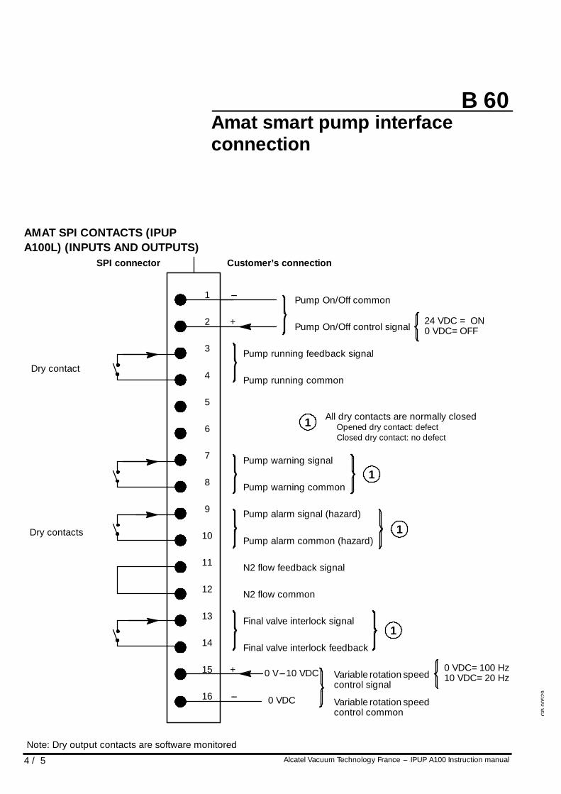
AMAT SPI CONTACTS (IPUPA100P) (INPUTS AND OUTPUTS)
0 V---10 VDC
0 VDC
Dry contacts
Dry contact
1
2
3
4
5
6
7
8
9
10
11
12
13
14
15
16
---
+
+
---
SPI connector Customer’s connection
Final valve interlock feedback
Pump On/Off common
Pump On/Off control signal
Pump running feedback signal
Pump running common
Pump warning signal
Pump warning common
Pump alarm signal (hazard)
Pump alarm common (hazard)
N2 flow feedback signal
N2 flow common
Final valve interlock signal
Variable rotation speedcontrol signal
Variable rotation speedcontrol common
24VDC = ON0VDC=OFF
0 VDC=100 Hz10 VDC=20 Hz
All dry contacts are normally closedOpened dry contact: defectClosed dry contact: no defect
1
1
1
1
1
Note: Dry output contacts are software monitored
GB
0052
9
B 60
3 / 5Alcatel Vacuum Technology France --- IPUP A100 Instruction manual
Amat smart pump interfaceconnection
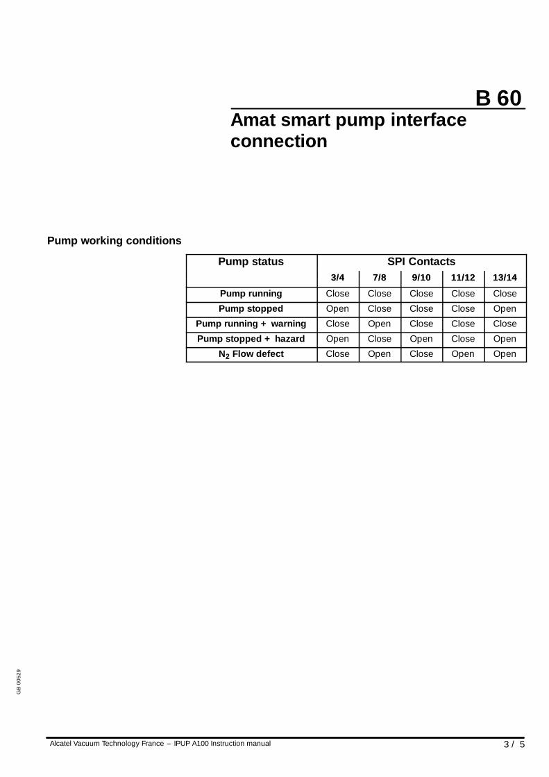
Pump working conditions
Pump status SPI ContactsPump status3/4 7/8 9/10 11/12 13/143/4 7/8 9/10 11/12 13/14
Pump running Close Close Close Close Close
Pump stopped Open Close Close Close Open
Pump running + warning Close Open Close Close Close
Pump stopped + hazard Open Close Open Close Open
N2 Flow defect Close Open Close Open Open
GB
0052
9
B 60
4 / 5 Alcatel Vacuum Technology France --- IPUP A100 Instruction manual
Amat smart pump interfaceconnection
AMAT SPI CONTACTS (IPUPA100L) (INPUTS AND OUTPUTS)
0 V---10 VDC
0 VDC
Dry contacts
Dry contact
1
2
3
4
5
6
7
8
9
10
11
12
13
14
15
16
---
+
+
---
SPI connector Customer’s connection
Final valve interlock feedback
Pump On/Off common
Pump On/Off control signal
Pump running feedback signal
Pump running common
Pump warning signal
Pump warning common
Pump alarm signal (hazard)
Pump alarm common (hazard)
N2 flow feedback signal
N2 flow common
Final valve interlock signal
Variable rotation speedcontrol signal
Variable rotation speedcontrol common
24 VDC = ON0 VDC=OFF
0 VDC=100 Hz10 VDC=20 Hz
All dry contacts are normally closedOpened dry contact: defectClosed dry contact: no defect
1
1
1
1
Note: Dry output contacts are software monitored
GB
0052
9
B 60
5 / 5Alcatel Vacuum Technology France --- IPUP A100 Instruction manual
Amat smart pump interfaceconnection
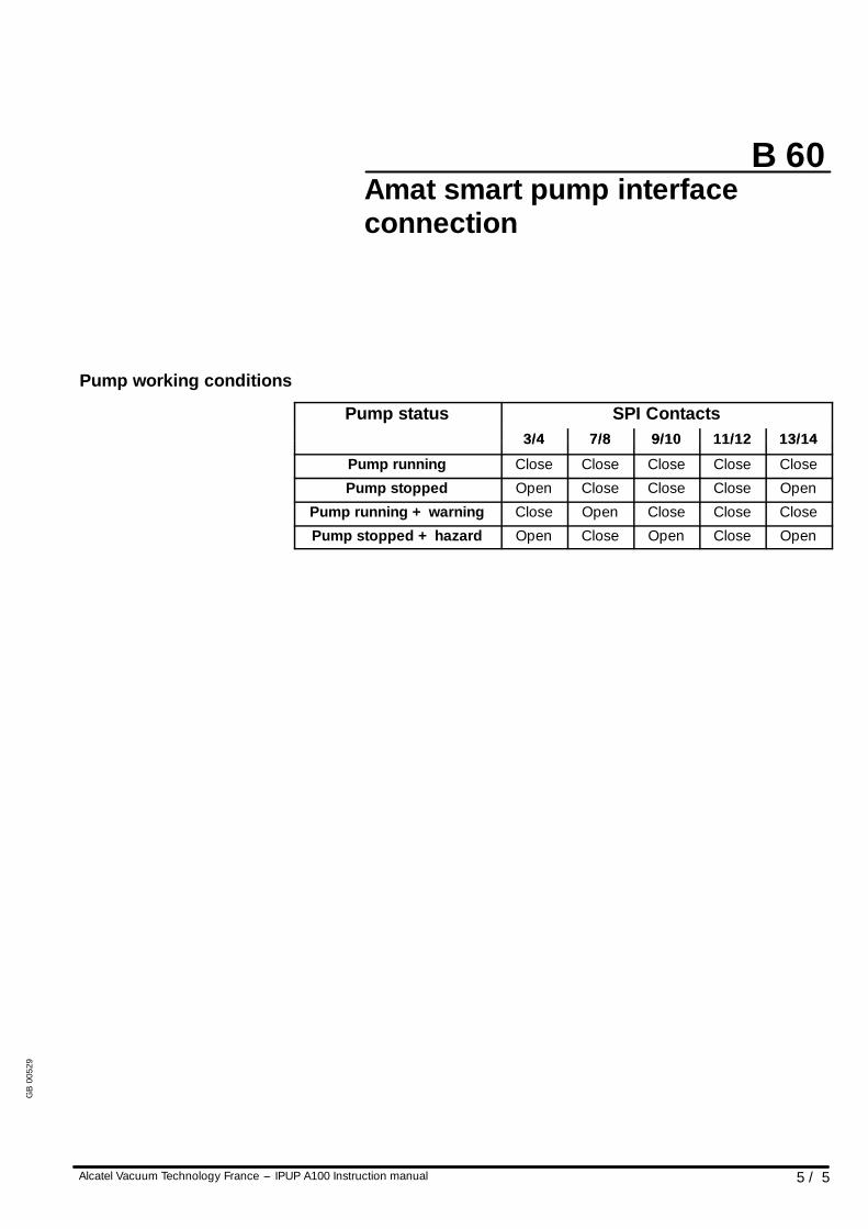
Pump working conditions
Pump status SPI ContactsPump status3/4 7/8 9/10 11/12 13/143/4 7/8 9/10 11/12 13/14
Pump running Close Close Close Close Close
Pump stopped Open Close Close Close Open
Pump running + warning Close Open Close Close Close
Pump stopped + hazard Open Close Open Close Open
GB
0052
9
B 70
1 / 1Alcatel Vacuum Technology France --- IPUP A100 Instruction manual
RS 232 or RS 485 link wiring
At first power---on, the user will find the initial factory---set configuration(see C 50).
The setting can be modified through the corresponding monitoringmenu (see C 90).
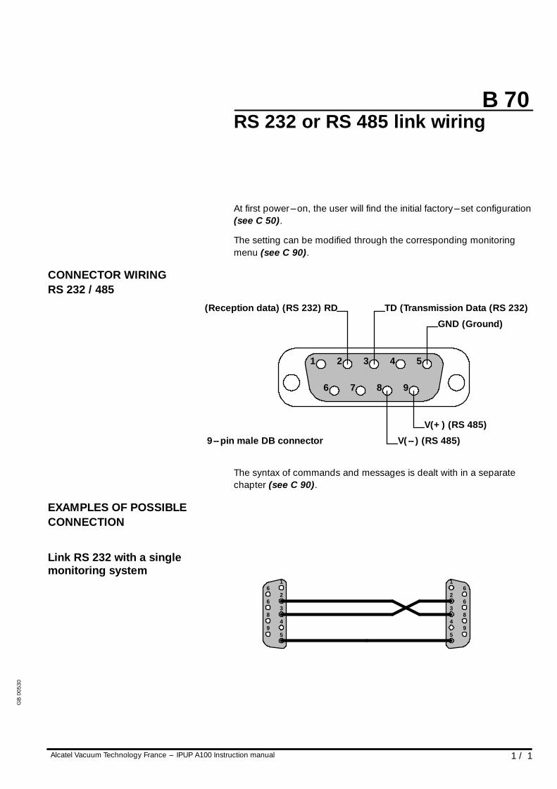
CONNECTOR WIRINGRS 232 / 485
6 7 8 9
2 3 4 51
(Reception data) (RS 232) RD TD (Transmission Data (RS 232)
GND (Ground)
V(+) (RS 485)
V(-- ) (RS 485)9--pin male DB connector
The syntax of commands and messages is dealt with in a separatechapter (see C 90).
EXAMPLES OF POSSIBLECONNECTION
Link RS 232 with a singlemonitoring system
6
6
8
9
2
3
4
5
16
6
8
9
2
3
4
5
1
GB
0053
0
!WARNING
B 80
1 / 1Alcatel Vacuum Technology France --- IPUP A100 Instruction manual
Connection to the pumpingcircuit
l Remove the plastic caps blocking the inlet and exhaust holes;these components prevent foreign bodies from entering the pumpduring transport and storage.
For safety reasons, any accessories connected to the inlet andexhaust must be made of materials compatible with pumped gases.
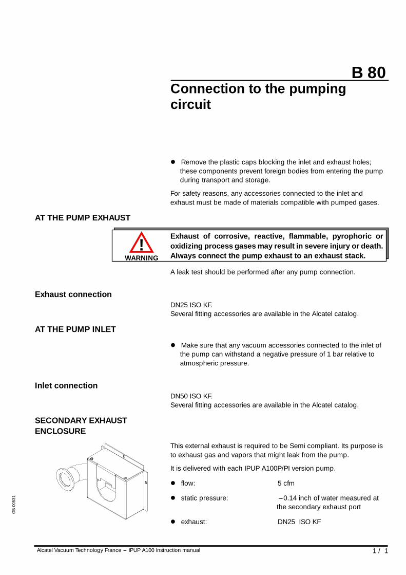
AT THE PUMP EXHAUST
Exhaust of corrosive, reactive, flammable, pyrophoric oroxidizing process gases may result in severe injury or death.Always connect the pump exhaust to an exhaust stack.
A leak test should be performed after any pump connection.
Exhaust connectionDN25 ISO KF.Several fitting accessories are available in the Alcatel catalog.
AT THE PUMP INLET
l Make sure that any vacuum accessories connected to the inlet ofthe pump can withstand a negative pressure of 1 bar relative toatmospheric pressure.
Inlet connectionDN50 ISO KF.Several fitting accessories are available in the Alcatel catalog.
SECONDARY EXHAUSTENCLOSURE
This external exhaust is required to be Semi compliant. Its purpose isto exhaust gas and vapors that might leak from the pump.
It is delivered with each IPUP A100P/PI version pump.
l flow: 5 cfm
l static pressure: ---0.14 inch of water measured atthe secondary exhaust port
l exhaust: DN25 ISO KF
GB
0053
1
Chapter C
Alcatel Vacuum Technology France --- IPUP A100 Instruction manual 1 / 1
IPUP A100 instruction manual
OperationOperating mode C 10. . . . . . . . . . . . . . . . . . . . . . . . . .
Start up of the monitoring system C 20. . . . . . . . . . . .
Use of the monitoring system for pumpingoperation C 30. . . . . . . . . . . . . . . . . . . . . . . . . . . . . . .
Monitoring system parameters C 40. . . . . . . . . . . . . .
Monitoring system function tableIPUP A100P version C 50. . . . . . . . . . . . . . . . . . . . . . .
Monitoring system function tableIPUP A100L version C 51. . . . . . . . . . . . . . . . . . . . . . .
Gas purge and temperature according to thesemiconductor processes C 60. . . . . . . . . . . . . . . . . .
Saving and loading of pump configuration(with monitoring system) C 70. . . . . . . . . . . . . . . . . . . . .
Monitoring system setting for transport C 80. . . . . . .
Use of the serial link C 90. . . . . . . . . . . . . . . . . . . . . . .
GB
0053
2
C 10
1 / 2Alcatel Vacuum Technology France --- IPUP A100 Instruction manual
Operating mode
DIFFERENT CONTROL MODESAccording to the monitoring configuration and wiring, the pump canbe:
l controlled remotely using the Amat SPI connector,
l controlled remotely by serial link (RS 232 / RS 485),
l controlled locally with a hand held display module by pressing thecontrol key (the star appears).
The pump can be equipped with a hand held display module,connected in front of the frame.
This hand held display module allows the user to:
l set / modify pump parameters,
l review operation parameters,
l start/stop the pump (POWER START and CONTROL REMOTEDISABLED)
l start/stop the N2 purge if parameters are configured.
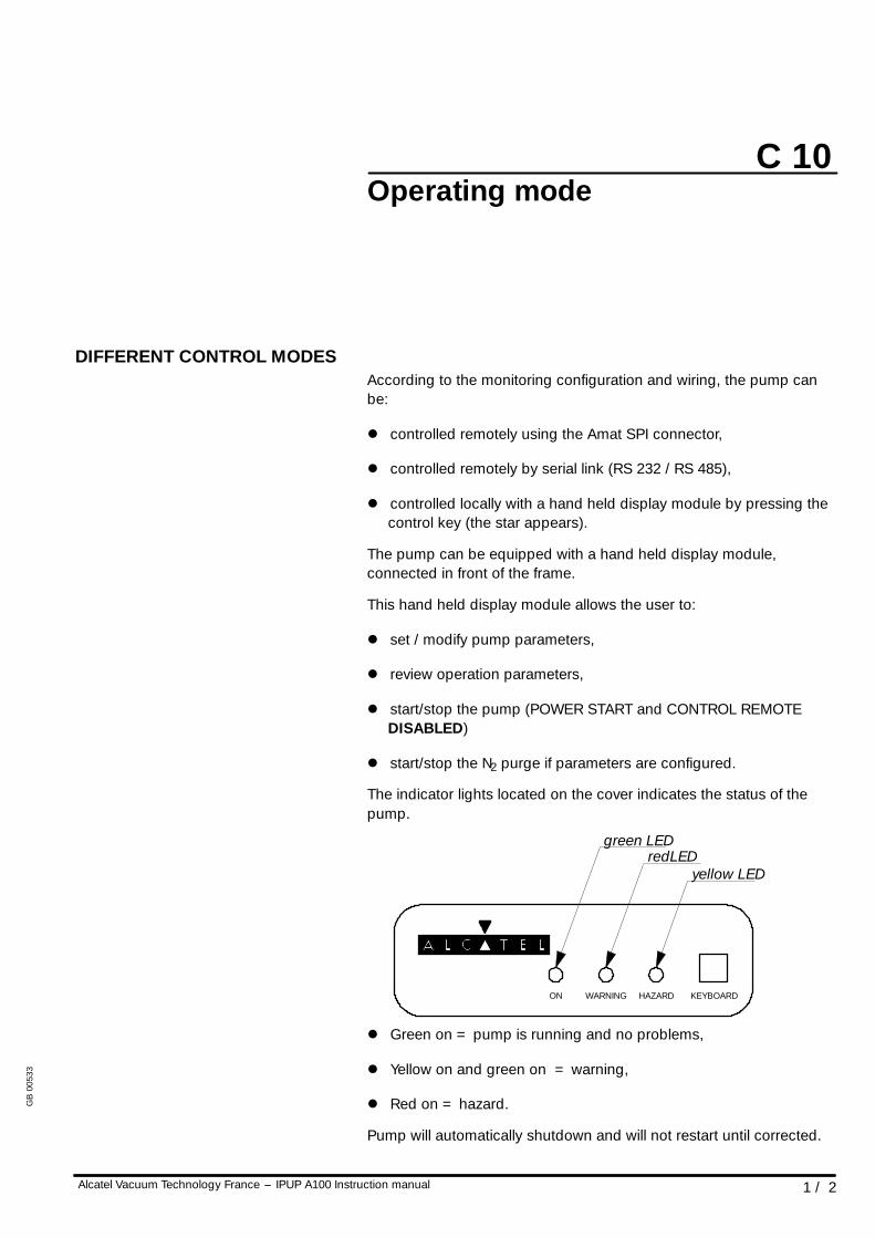
The indicator lights located on the cover indicates the status of thepump.
ON WARNING HAZARD KEYBOARD
redLEDyellow LED
green LED
l Green on = pump is running and no problems,
l Yellow on and green on = warning,
l Red on = hazard.
Pump will automatically shutdown and will not restart until corrected.
GB
0053
3
C 10
Alcatel Vacuum Technology France --- IPUP A100 Instruction manual2 / 2
Operating mode
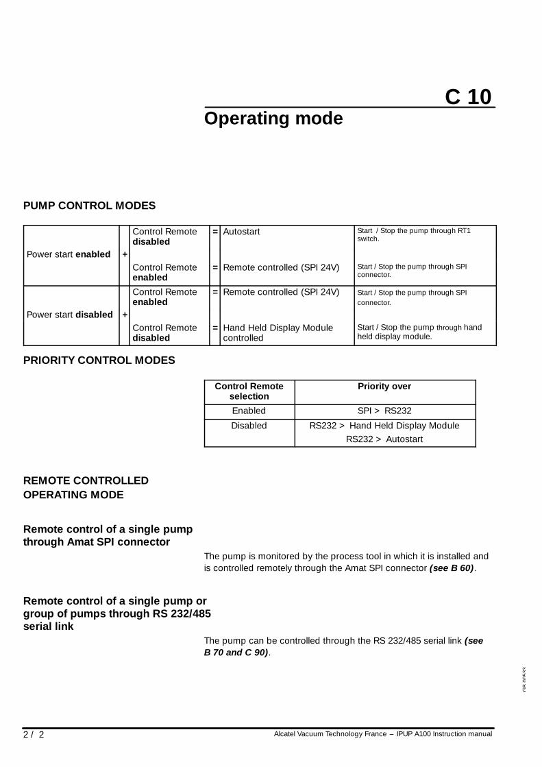
PUMP CONTROL MODES
Control Remotedisabled
= Autostart Start / Stop the pump through RT1switch.
Power start enabled +Power start enabled +Control Remoteenabled
= Remote controlled (SPI 24V) Start / Stop the pump through SPIconnector.
Control Remoteenabled
= Remote controlled (SPI 24V) Start / Stop the pump through SPIconnector.
Power start disabled +Power start disabled +Control Remotedisabled
= Hand Held Display Modulecontrolled
Start / Stop the pump through handheld display module.
PRIORITY CONTROL MODES
Control Remoteselection
Priority over
Enabled SPI > RS232
Disabled RS232 > Hand Held Display ModuleRS232 > Autostart
REMOTE CONTROLLEDOPERATING MODE
Remote control of a single pumpthrough Amat SPI connector
The pump is monitored by the process tool in which it is installed andis controlled remotely through the Amat SPI connector (see B 60).
Remote control of a single pump orgroup of pumps through RS 232/485serial link
The pump can be controlled through the RS 232/485 serial link (seeB 70 and C 90).
GB
0053
3
C 20
1 / 3Alcatel Vacuum Technology France --- IPUP A100 Instruction manual
Start up of the monitoring system
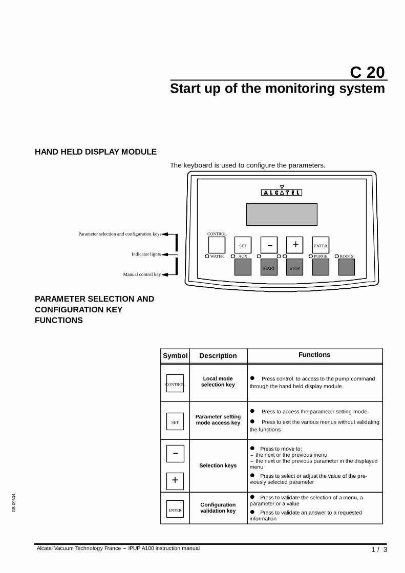
HAND HELD DISPLAY MODULEThe keyboard is used to configure the parameters.
WATER AUX
START STOP
PURGE ROOTS
SET -- + ENTER
CONTROLParameter selection and configuration keys
Indicator lights
Manual control key
PARAMETER SELECTION ANDCONFIGURATION KEYFUNCTIONS
Symbol Description Functions
CONTROLLocal mode
selection keyl Press control to access to the pump commandthrough the hand held display module
SETParameter settingmode access key
l Press to access the parameter setting mode
l Press to exit the various menus without validatingthe functions
--
+Selection keys
l Press to move to:--- the next or the previous menu--- the next or the previous parameter in the displayedmenu
l Press to select or adjust the value of the pre-viously selected parameter
ENTERConfigurationvalidation key
l Press to validate the selection of a menu, aparameter or a value
l Press to validate an answer to a requestedinformation
GB
0053
4
C 20
2 / 3 Alcatel Vacuum Technology France --- IPUP A100 Instruction manual
Start up of the monitoring system
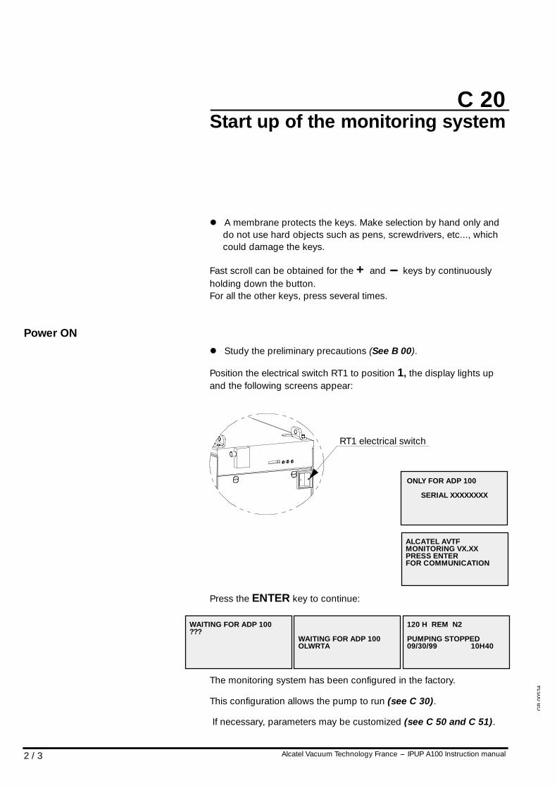
l A membrane protects the keys. Make selection by hand only anddo not use hard objects such as pens, screwdrivers, etc..., whichcould damage the keys.
Fast scroll can be obtained for the + and --- keys by continuouslyholding down the button.For all the other keys, press several times.
Power ONl Study the preliminary precautions (See B 00).
Position the electrical switch RT1 to position 1, the display lights upand the following screens appear:
ONLY FOR ADP 100
SERIAL XXXXXXXX
RT1 electrical switch
ALCATEL AVTFMONITORING VX.XXPRESS ENTERFOR COMMUNICATION
Press the ENTER key to continue:
WAITING FOR ADP 100???
WAITING FOR ADP 100OLWRTA
120 H REM N2
PUMPING STOPPED09/30/99 10H40
The monitoring system has been configured in the factory.
This configuration allows the pump to run (see C 30).
If necessary, parameters may be customized (see C 50 and C 51).
GB
0053
4
C 20
3 / 3Alcatel Vacuum Technology France --- IPUP A100 Instruction manual
Start up of the monitoring system
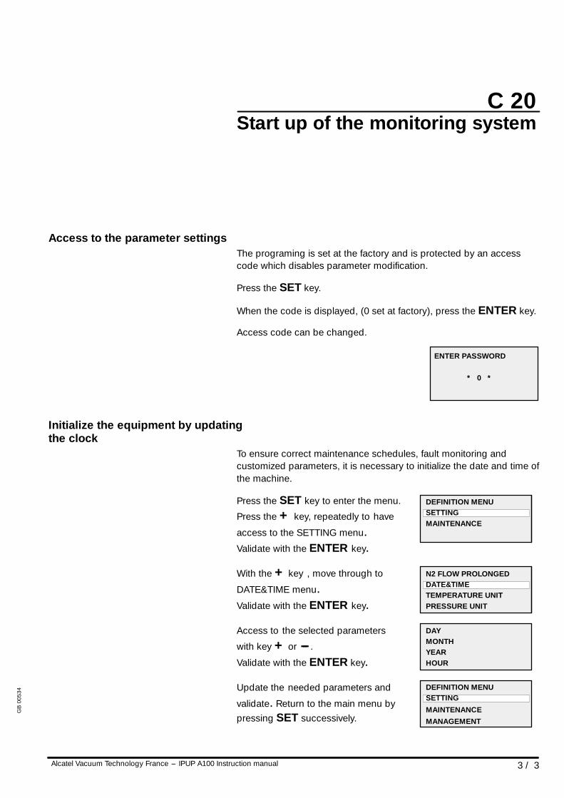
Access to the parameter settingsThe programing is set at the factory and is protected by an accesscode which disables parameter modification.
Press the SET key.
When the code is displayed, (0 set at factory), press the ENTER key.
Access code can be changed.
ENTER PASSWORD
* 0 *
Initialize the equipment by updatingthe clock
To ensure correct maintenance schedules, fault monitoring andcustomized parameters, it is necessary to initialize the date and time ofthe machine.
Press the SET key to enter the menu.
Press the + key, repeatedly to have
access to the SETTING menu.Validate with the ENTER key.
With the + key , move through to
DATE&TIME menu.Validate with the ENTER key.
Access to the selected parameters
with key + or --- .
Validate with the ENTER key.
Update the needed parameters and
validate. Return to the main menu bypressing SET successively.
DEFINITION MENUSETTINGMAINTENANCE
N2 FLOW PROLONGEDDATE&TIMETEMPERATURE UNITPRESSURE UNIT
DAYMONTHYEARHOUR
DEFINITION MENUSETTINGMAINTENANCEMANAGEMENT
GB
0053
4
C 30
1 / 3Alcatel Vacuum Technology France --- IPUP A100 Instruction manual
Use of the monitoring system forpumping operation
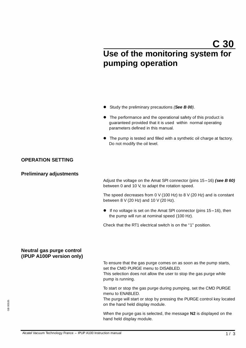
l Study the preliminary precautions (See B 00).
l The performance and the operational safety of this product isguaranteed provided that it is used within normal operatingparameters defined in this manual.
l The pump is tested and filled with a synthetic oil charge at factory.Do not modify the oil level.
OPERATION SETTING
Preliminary adjustmentsAdjust the voltage on the Amat SPI connector (pins 15---16) (see B 60)between 0 and 10 V, to adapt the rotation speed.
The speed decreases from 0 V (100 Hz) to 8 V (20 Hz) and is constantbetween 8 V (20 Hz) and 10 V (20 Hz).
l If no voltage is set on the Amat SPI connector (pins 15---16), thenthe pump will run at nominal speed (100 Hz).
Check that the RT1 electrical switch is on the “1” position.
Neutral gas purge control(IPUP A100P version only)
To ensure that the gas purge comes on as soon as the pump starts,set the CMD PURGE menu to DISABLED.This selection does not allow the user to stop the gas purge whilepump is running.
To start or stop the gas purge during pumping, set the CMD PURGEmenu to ENABLED.The purge will start or stop by pressing the PURGE control key locatedon the hand held display module.
When the purge gas is selected, the message N2 is displayed on thehand held display module.
GB
0053
5
C 30
2 / 3 Alcatel Vacuum Technology France --- IPUP A100 Instruction manual
Use of the monitoring system forpumping operation
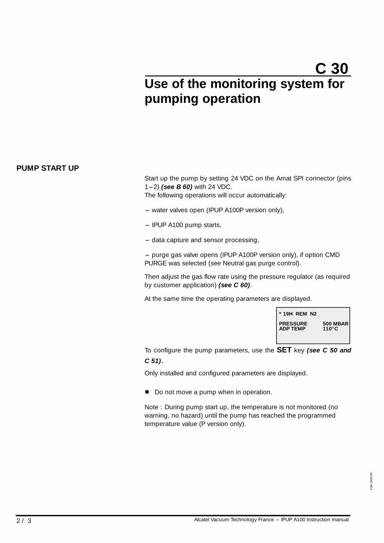
PUMP START UPStart up the pump by setting 24 VDC on the Amat SPI connector (pins1---2) (see B 60) with 24 VDC.The following operations will occur automatically:
--- water valves open (IPUP A100P version only),
--- IPUP A100 pump starts,
--- data capture and sensor processing,
--- purge gas valve opens (IPUP A100P version only), if option CMDPURGE was selected (see Neutral gas purge control).
Then adjust the gas flow rate using the pressure regulator (as requiredby customer application) (see C 60).
At the same time the operating parameters are displayed.
* 19H REM N2
PRESSUREADP TEMP
500 MBAR110° C
To configure the pump parameters, use the SET key (see C 50 andC 51).Only installed and configured parameters are displayed.
l Do not move a pump when in operation.
Note : During pump start up, the temperature is not monitored (nowarning, no hazard) until the pump has reached the programmedtemperature value (P version only).
GB
0053
5
C 30
3 / 3Alcatel Vacuum Technology France --- IPUP A100 Instruction manual
Use of the monitoring system forpumping operation
OPERATION MONITORING
During operation, the user is warned of an operating incident by:
--- One or several faults are displayed on the screen, in alternance withmonitoring parameters. When these faults are activated, themonitoring triggers the warning phase which is followed by the hazardphase. The period of time for these phases can be set.
--- Indicator lights on the front panel are illuminated.
--- Indicator lights on the hand held display module unit are illuminated.
--- The fault contacts on the Amat SPI connector at the rear of the pumpare open.
--- Pumping is stopped when an hazard threshold is reached.
A list of incidents is given in chapter D.
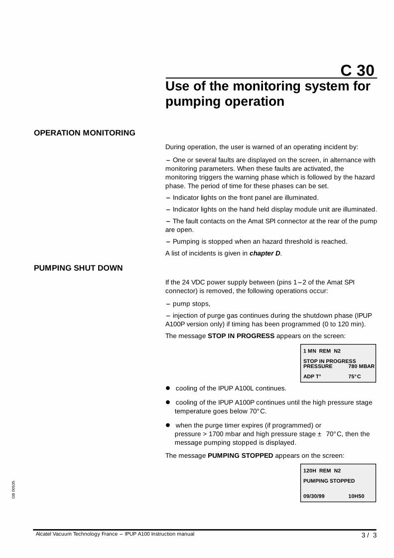
PUMPING SHUT DOWN
If the 24 VDC power supply between (pins 1---2 of the Amat SPIconnector) is removed, the following operations occur:
--- pump stops,
--- injection of purge gas continues during the shutdown phase (IPUPA100P version only) if timing has been programmed (0 to 120 min).
The message STOP IN PROGRESS appears on the screen:
1 MN REM N2
STOP IN PROGRESSPRESSURE
ADP T°
780 MBAR
75° C
l cooling of the IPUP A100L continues.
l cooling of the IPUP A100P continues until the high pressure stagetemperature goes below 70° C.
l when the purge timer expires (if programmed) orpressure > 1700 mbar and high pressure stage ± 70° C, then themessage pumping stopped is displayed.
The message PUMPING STOPPED appears on the screen:
120H REM N2
PUMPING STOPPED
09/30/99 10H50GB
0053
5
C 40
1 / 1Alcatel Vacuum Technology France --- IPUP A100 Instruction manual
Monitoring system parameters
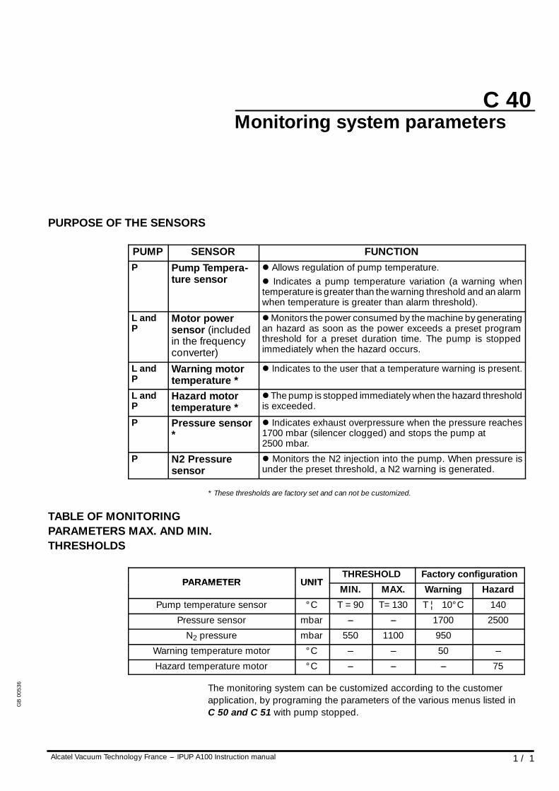
PURPOSE OF THE SENSORS
PUMP SENSOR FUNCTIONP Pump Tempera-
ture sensorl Allows regulation of pump temperature.l Indicates a pump temperature variation (a warning whentemperature is greater than the warning threshold and an alarmwhen temperature is greater than alarm threshold).
L andP
Motor powersensor (includedin the frequencyconverter)
l Monitors the power consumed by the machine by generatingan hazard as soon as the power exceeds a preset programthreshold for a preset duration time. The pump is stoppedimmediately when the hazard occurs.
L andP
Warning motortemperature *
l Indicates to the user that a temperature warning is present.
L andP
Hazard motortemperature *
l The pump is stopped immediately when the hazard thresholdis exceeded.
P Pressure sensor*
l Indicates exhaust overpressure when the pressure reaches1700 mbar (silencer clogged) and stops the pump at2500 mbar.
P N2 Pressuresensor
l Monitors the N2 injection into the pump. When pressure isunder the preset threshold, a N2 warning is generated.
* These thresholds are factory set and can not be customized.
TABLE OF MONITORINGPARAMETERS MAX. AND MIN.THRESHOLDS
PARAMETER UNITTHRESHOLD Factory configuration
PARAMETER UNITMIN. MAX. Warning Hazard
Pump temperature sensor ° C T =90 T=130 T ¦ 10° C 140
Pressure sensor mbar --- --- 1700 2500
N2 pressure mbar 550 1100 950
Warning temperature motor ° C --- --- 50 ---
Hazard temperature motor ° C --- --- --- 75
The monitoring system can be customized according to the customerapplication, by programing the parameters of the various menus listed inC 50 and C 51 with pump stopped.
GB
0053
6
C 50
1 / 4Alcatel Vacuum Technology France --- IPUP A100 Instruction manual
Monitoring system function tableIPUP A100P version
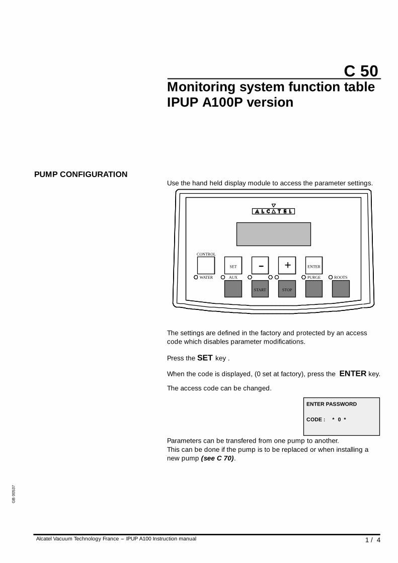
PUMP CONFIGURATIONUse the hand held display module to access the parameter settings.
WATER AUX
START STOP
PURGE ROOTS
SET -- + ENTER
CONTROL
The settings are defined in the factory and protected by an accesscode which disables parameter modifications.
Press the SET key .
When the code is displayed, (0 set at factory), press the ENTER key.
The access code can be changed.
ENTER PASSWORD
CODE : * 0 *
Parameters can be transfered from one pump to another.This can be done if the pump is to be replaced or when installing anew pump (see C 70).
GB
0053
7
CAUTION!
C 50
2 / 4 Alcatel Vacuum Technology France --- IPUP A100 Instruction manual
Monitoring system function tableIPUP A100P version
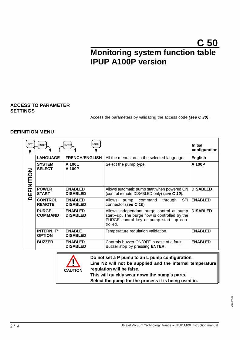
ACCESS TO PARAMETERSETTINGS
Access the parameters by validating the access code (see C 30).
DEFINITION MENU
SET ENTER ENTER ENTER Initialconfiguration
LANGUAGE FRENCH/ENGLISH All the menus are in the selected language. English
NIT
ION
SYSTEMSELECT
A 100LA 100P
Select the pump type. A 100P
DE
FIN
POWERSTART
ENABLEDDISABLED
Allows automatic pump start when powered ON(control remote DISABLED only) (see C 10).
DISABLED
DE
CONTROLREMOTE
ENABLEDDISABLED
Allows pump command through SPIconnector (see C 10).
ENABLED
PURGECOMMAND
ENABLEDDISABLED
Allows independant purge control at pumpstart ---up. The purge flow is controlled by thePURGE control key or pump start ---up con-trolled.
DISABLED
INTERN. T°OPTION
ENABLEDISABLED
Temperature regulation validation. ENABLED
BUZZER ENABLEDDISABLED
Controls buzzer ON/OFF in case of a fault.Buzzer stop by pressing ENTER.
ENABLED
Do not set a P pump to an L pump configuration.Line N2 will not be supplied and the internal temperatureregulation will be false.This will quickly wear down the pump’s parts.Select the pump for the process it is being used in.
GB
0053
7
C 50
3 / 4Alcatel Vacuum Technology France --- IPUP A100 Instruction manual
Monitoring system function tableIPUP A100P version
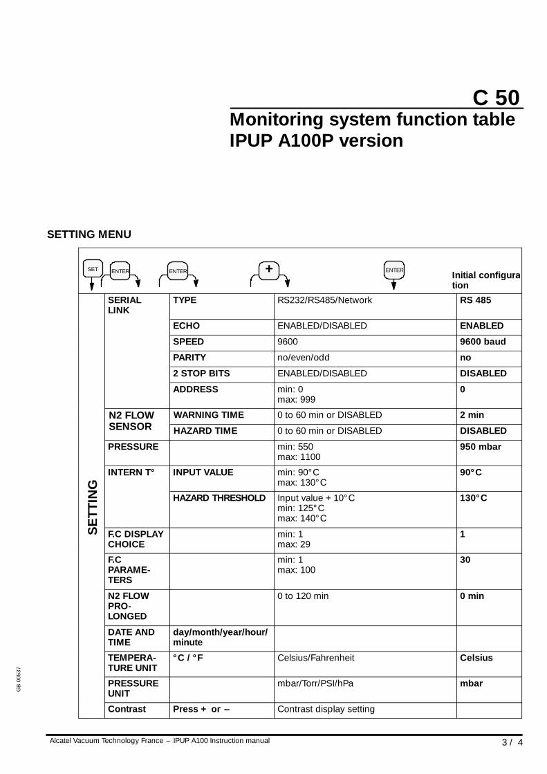
SETTING MENU
SET ENTER ENTER ENTER+ Initial configuration
SERIALLINK
TYPE RS232/RS485/Network RS 485
ECHO ENABLED/DISABLED ENABLED
SPEED 9600 9600 baud
PARITY no/even/odd no
2 STOP BITS ENABLED/DISABLED DISABLED
ADDRESS min: 0max: 999
0
N2 FLOWSENSOR
WARNING TIME 0 to 60 min or DISABLED 2 minN2 FLOWSENSOR HAZARD TIME 0 to 60 min or DISABLED DISABLED
PRESSURE min: 550max: 1100
950 mbar
NG
INTERN T° INPUT VALUE min: 90° Cmax: 130° C
90° C
SE
TTIN
G
HAZARD THRESHOLD Input value +10° Cmin: 125° Cmax: 140° C
130° C
SE
F.C DISPLAYCHOICE
min: 1max: 29
1
F.CPARAME-TERS
min: 1max: 100
30
N2 FLOWPRO-LONGED
0 to 120 min 0 min
DATE ANDTIME
day/month/year/hour/minute
TEMPERA-TURE UNIT
° C / ° F Celsius/Fahrenheit Celsius
PRESSUREUNIT
mbar/Torr/PSI/hPa mbar
Contrast Press + or -- Contrast display setting
GB
0053
7
C 50
4 / 4 Alcatel Vacuum Technology France --- IPUP A100 Instruction manual
Monitoring system function tableIPUP A100P version
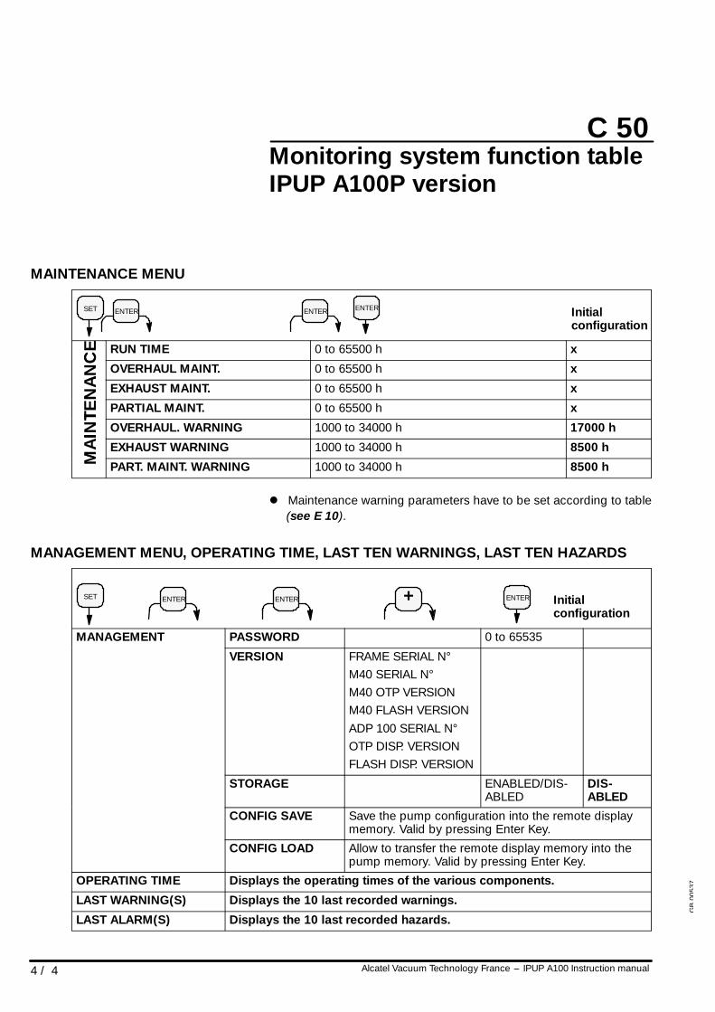
MAINTENANCE MENU
SET ENTER ENTER ENTER Initialconfiguration
CE RUN TIME 0 to 65500 h x
AN
C
OVERHAUL MAINT. 0 to 65500 h x
NA
N
EXHAUST MAINT. 0 to 65500 h x
TEN
PARTIAL MAINT. 0 to 65500 h x
INT
OVERHAUL. WARNING 1000 to 34000 h 17000 h
MA
I
EXHAUST WARNING 1000 to 34000 h 8500 h
M PART. MAINT. WARNING 1000 to 34000 h 8500 h
l Maintenance warning parameters have to be set according to table(see E 10).
MANAGEMENT MENU, OPERATING TIME, LAST TEN WARNINGS, LAST TEN HAZARDS
SET ENTER ENTER Initialconfiguration
ENTER+
MANAGEMENT PASSWORD 0 to 65535MANAGEMENT
VERSION FRAME SERIAL N°M40 SERIAL N°M40 OTP VERSIONM40 FLASH VERSIONADP 100 SERIAL N°OTP DISP. VERSIONFLASH DISP. VERSION
STORAGE ENABLED/DIS-ABLED
DIS-ABLED
CONFIG SAVE Save the pump configuration into the remote displaymemory. Valid by pressing Enter Key.
CONFIG LOAD Allow to transfer the remote display memory into thepump memory. Valid by pressing Enter Key.
OPERATING TIME Displays the operating times of the various components.
LAST WARNING(S) Displays the 10 last recorded warnings.
LAST ALARM(S) Displays the 10 last recorded hazards.
GB
0053
7
C 51
1 / 4Alcatel Vacuum Technology France --- IPUP A100 Instruction manual
Monitoring system function tableIPUP A100L version
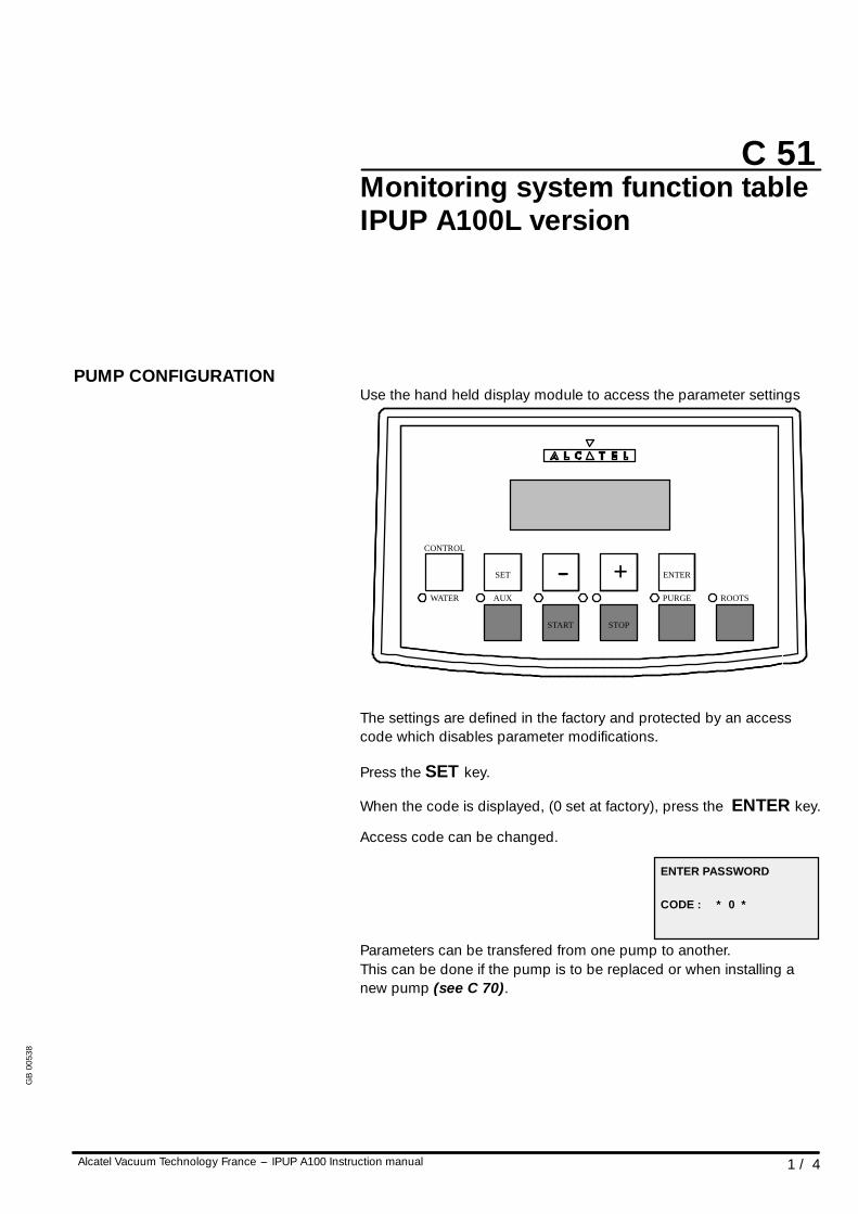
PUMP CONFIGURATIONUse the hand held display module to access the parameter settings
WATER AUX
START STOP
PURGE ROOTS
SET -- + ENTER
CONTROL
The settings are defined in the factory and protected by an accesscode which disables parameter modifications.
Press the SET key.
When the code is displayed, (0 set at factory), press the ENTER key.
Access code can be changed.
ENTER PASSWORD
CODE : * 0 *
Parameters can be transfered from one pump to another.This can be done if the pump is to be replaced or when installing anew pump (see C 70).
GB
0053
8
CAUTION!
C 51
2 / 4 Alcatel Vacuum Technology France --- IPUP A100 Instruction manual
Monitoring system function tableIPUP A100L version
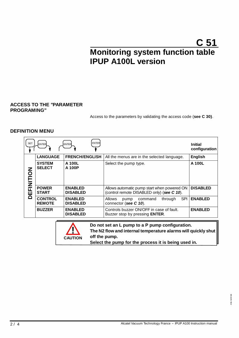
ACCESS TO THE ”PARAMETERPROGRAMING”
Access to the parameters by validating the access code (see C 30).
DEFINITION MENU
SET ENTER ENTER ENTER Initialconfiguration
LANGUAGE FRENCH/ENGLISH All the menus are in the selected language. English
NIT
ION
SYSTEMSELECT
A 100LA 100P
Select the pump type. A 100L
DE
FIN
POWERSTART
ENABLEDDISABLED
Allows automatic pump start when powered ON(control remote DISABLED only) (see C 10).
DISABLED
DE
CONTROLREMOTE
ENABLEDDISABLED
Allows pump command through SPIconnector (see C 10).
ENABLED
BUZZER ENABLEDDISABLED
Controls buzzer ON/OFF in case of fault.Buzzer stop by pressing ENTER.
ENABLED
Do not set an L pump to a P pump configuration.The N2 flow and internal temperature alarms will quickly shutoff the pump.Select the pump for the process it is being used in.
GB
0053
8
C 51
3 / 4Alcatel Vacuum Technology France --- IPUP A100 Instruction manual
Monitoring system function tableIPUP A100L version
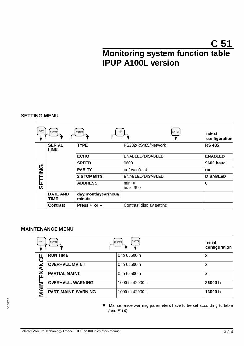
SETTING MENU
SET ENTER ENTER ENTER+ Initialconfiguration
SERIALLINK
TYPE RS232/RS485/Network RS 485
ECHO ENABLED/DISABLED ENABLED
G
SPEED 9600 9600 baud
ING PARITY no/even/odd no
TTIN
2 STOP BITS ENABLED/DISABLED DISABLED
SE
T
ADDRESS min: 0max: 999
0
DATE ANDTIME
day/month/year/hour/minute
Contrast Press + or -- Contrast display setting
MAINTENANCE MENU
SET ENTER ENTER ENTER Initialconfiguration
CE RUN TIME 0 to 65500 h x
NA
NC
OVERHAUL MAINT. 0 to 65500 h x
TEN
A
PARTIAL MAINT. 0 to 65500 h x
AIN
TE OVERHAUL. WARNING 1000 to 42000 h 26000 h
MA
I
PART. MAINT. WARNING 1000 to 42000 h 13000 h
l Maintenance warning parameters have to be set according to table(see E 10).
GB
0053
8
C 51
4 / 4 Alcatel Vacuum Technology France --- IPUP A100 Instruction manual
Monitoring system function tableIPUP A100L version
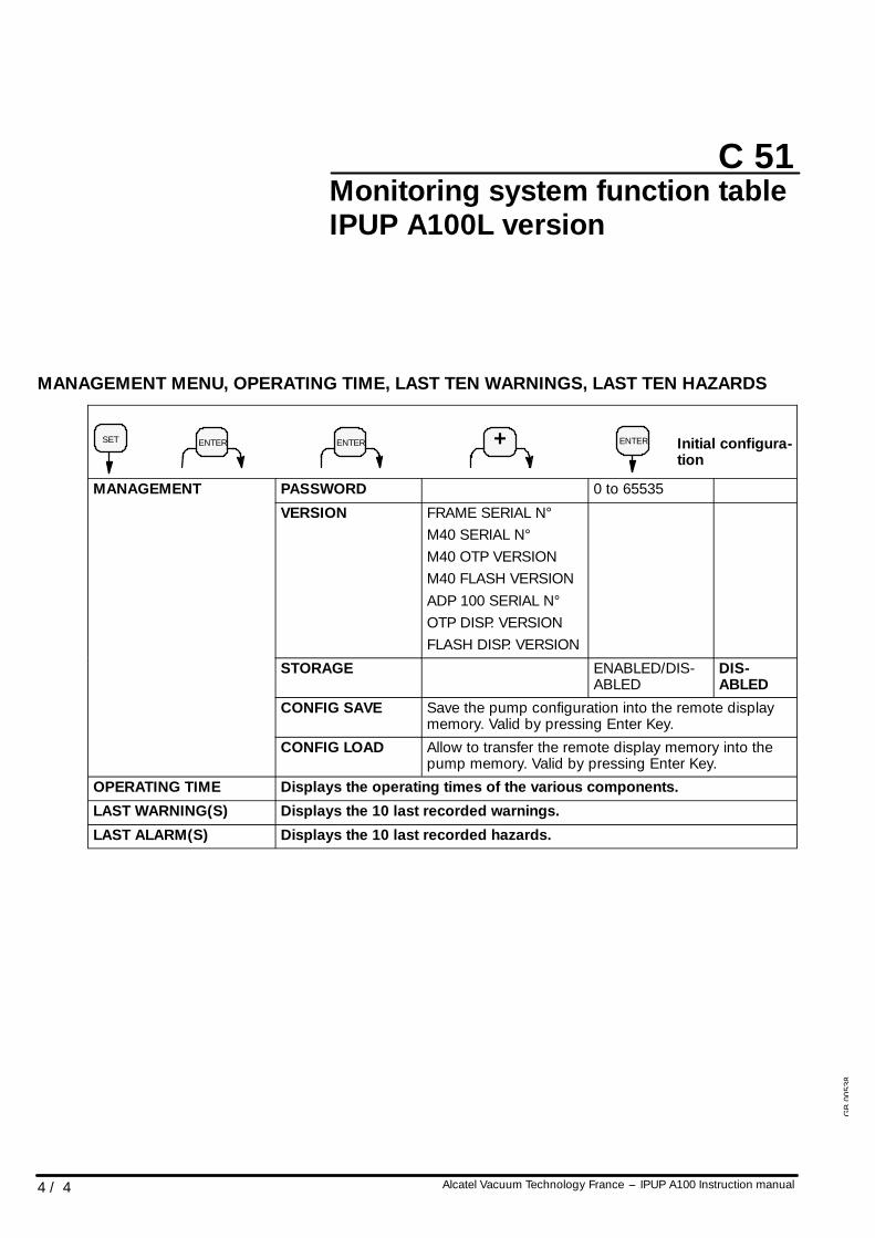
MANAGEMENT MENU, OPERATING TIME, LAST TEN WARNINGS, LAST TEN HAZARDS
SET ENTER ENTER Initial configura-tion
ENTER+
MANAGEMENT PASSWORD 0 to 65535MANAGEMENT
VERSION FRAME SERIAL N°M40 SERIAL N°M40 OTP VERSIONM40 FLASH VERSIONADP 100 SERIAL N°OTP DISP. VERSIONFLASH DISP. VERSION
STORAGE ENABLED/DIS-ABLED
DIS-ABLED
CONFIG SAVE Save the pump configuration into the remote displaymemory. Valid by pressing Enter Key.
CONFIG LOAD Allow to transfer the remote display memory into thepump memory. Valid by pressing Enter Key.
OPERATING TIME Displays the operating times of the various components.
LAST WARNING(S) Displays the 10 last recorded warnings.
LAST ALARM(S) Displays the 10 last recorded hazards.G
B00
538
C 60
1 / 1Alcatel Vacuum Technology France --- IPUP A100 Instruction manual
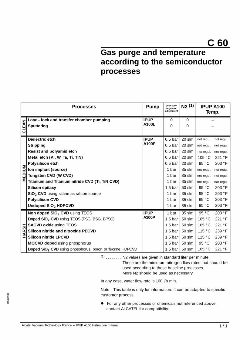
Gas purge and temperatureaccording to the semiconductorprocesses
Processes Pump pressureregulator
adjustmentN2 (1) IPUP A100
Temp.
CLE
AN Load-- lock and transfer chamber pumping
SputteringIPUPA100L
00
00
----
MED
IUM
Dielectric etchStrippingResist and polyamid etchMetal etch (Al, W, Ta, Ti, TiN)Polysilicon etchIon implant (source)Tungsten CVD (W CVD)Titanium and Titanium nitride CVD (Ti, TiN CVD)Silicon epitaxySiO2 CVD using silane as silicon sourcePolysilicon CVDUndoped SiO2 HDPCVD
IPUPA100P
0.5 bar0.5 bar0.5 bar0.5 bar0.5 bar1 bar1 bar1 bar
1.5 bar1 bar1 bar1 bar
20 slm20 slm20 slm20 slm20 slm35 slm35 slm35 slm50 slm35 slm35 slm35 slm
not regul.
not regul.
not regul.
105 ° C95 ° C
not regul.
not regul.
not regul.
95 ° C95 ° C95 ° C95 ° C
not regul.
not regul.
not regul.
221 ° F203 ° Fnot regul.
not regul.
not regul.
203 ° F203 ° F203 ° F203 ° F
HA
RS
H
Non doped SiO2 CVD using TEOSDoped SiO2 CVD using TEOS (PSG, BSG, BPSG)SACVD oxide using TEOSSilicon nitride and nitroxide PECVDSilicon nitride LPCVDMOCVD doped using phosphorusDoped SiO2 CVD using phosphorus, boron or fluorine HDPCVD
IPUPA100P
1 bar1.5 bar1.5 bar1.5 bar1.5 bar1.5 bar1.5 bar
35 slm50 slm50 slm50 slm50 slm50 slm50 slm
95 ° C105 ° C105 ° C115 ° C115 ° C95 ° C
105 ° C
203 ° F221 ° F221 ° F239 ° F239 ° F203 ° F221 ° F
(1) N2 values are given in standard liter per minute.. . . . . . . .These are the minimum nitrogen flow rates that should beused according to these baseline processes.More N2 should be used as necessary.
In any case, water flow rate is 100 l/h min.
Note : This table is only for information. It can be adapted to specificcustomer process.
l For any other processes or chemicals not referenced above,contact ALCATEL for compatibility.
GB
0053
9
CAUTION!
CAUTION!
C 70
1 / 1Alcatel Vacuum Technology France --- IPUP A100 Instruction manual
Saving and loading of pumpconfiguration (with monitoringsystem)
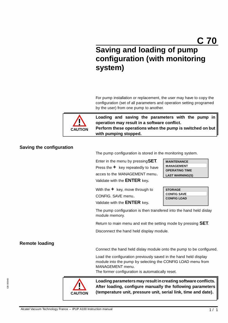
For pump installation or replacement, the user may have to copy theconfiguration (set of all parameters and operation setting programedby the user) from one pump to another.
Loading and saving the parameters with the pump inoperation may result in a software conflict.Perform these operations when the pump is switched on butwith pumping stopped.
Saving the configurationThe pump configuration is stored in the monitoring system.
Enter in the menu by pressingSET.
Press the + key repeatedly to have
acces to the MANAGEMENT menu.Validate with the ENTER key.
With the + key, move through to
CONFIG. SAVE menu.Validate with the ENTER key.The pump configuration is then transfered into the hand held dislaymodule memory.
Return to main menu and exit the setting mode by pressing SET.
Disconnect the hand held display module.
Remote loadingConnect the hand held dislay module onto the pump to be configured.
Load the configuration previously saved in the hand held displaymodule into the pump by selecting the CONFIG LOAD menu fromMANAGEMENT menu.The former configuration is automatically reset.
Loading parameters may result in creating software conflicts.After loading, configure manually the following parameters(temperature unit, pressure unit, serial link, time and date).
MANAGEMENTMAINTENANCE
OPERATING TIME
LAST WARNING(S)
STORAGECONFIG SAVECONFIG LOAD
GB
0054
0
C 80
1 / 1Alcatel Vacuum Technology France --- IPUP A100 Instruction manual
Monitoring system setting fortransport
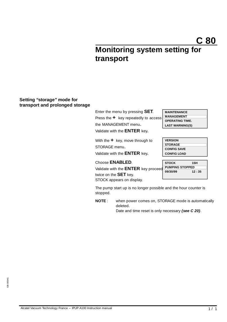
Setting “storage” mode fortransport and prolonged storage
Enter the menu by pressing SET.
Press the + key repeatedly to access
the MANAGEMENT menu.Validate with the ENTER key.
With the + key, move through to
STORAGE menu.Validate with the ENTER key.
Choose ENABLED.
Validate with the ENTER key proceedtwice on the SET key.STOCK appears on display.
The pump start up is no longer possible and the hour counter isstopped.
NOTE : when power comes on, STORAGE mode is automaticallydeleted.Date and time reset is only necessary (see C 20).
MAINTENANCEMANAGEMENTOPERATING TIME.LAST WARNING(S)
VERSIONSTORAGECONFIG SAVECONFIG LOAD
STOCK 15HPUMPING STOPPED09/30/99 12 : 35
GB
0054
1
C 90
1 / 6Alcatel Vacuum Technology France --- IPUP A100 Instruction manual
Use of the serial link
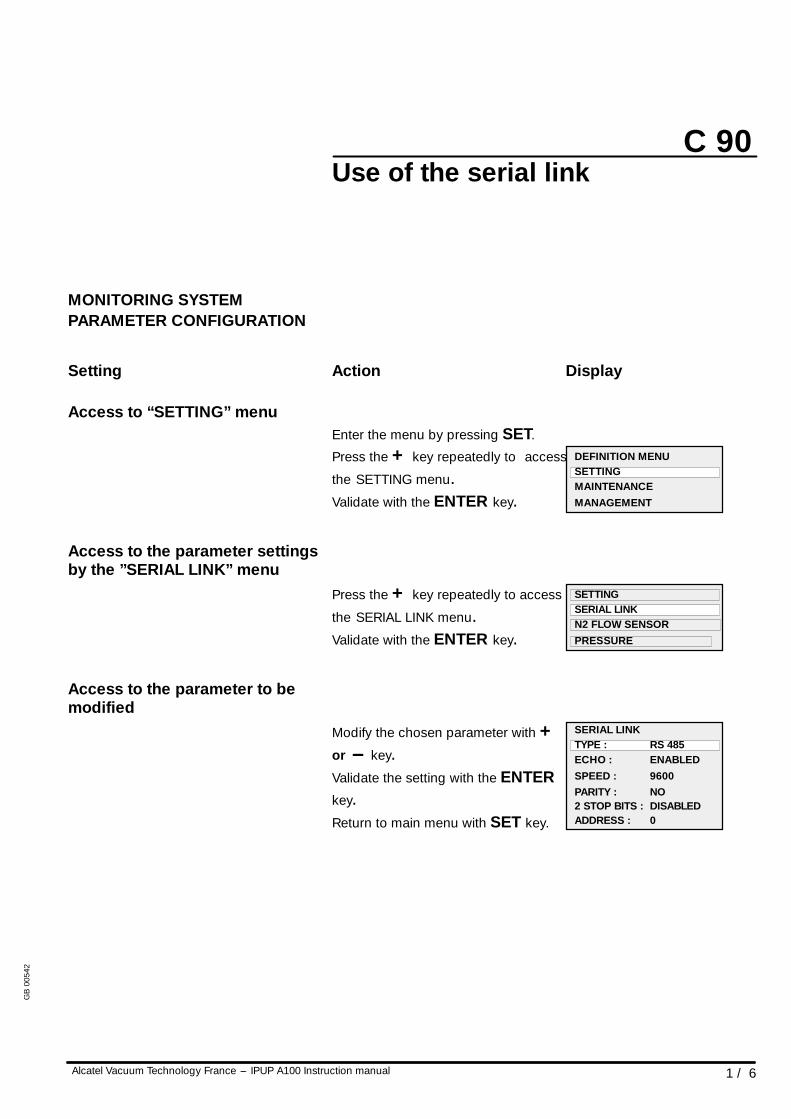
MONITORING SYSTEMPARAMETER CONFIGURATION
Setting Action Display
Access to “SETTING” menuEnter the menu by pressing SET.
Press the + key repeatedly to access
the SETTING menu.Validate with the ENTER key.
Access to the parameter settingsby the ”SERIAL LINK” menu
Press the + key repeatedly to access
the SERIAL LINK menu.Validate with the ENTER key.
Access to the parameter to bemodified
Modify the chosen parameter with +or --- key.Validate the setting with the ENTERkey.Return to main menu with SET key.
DEFINITION MENUSETTINGMAINTENANCEMANAGEMENT
SETTINGSERIAL LINKN2 FLOW SENSORPRESSURE
2 STOP BITS : DISABLED
SERIAL LINKTYPE : RS 485ECHO : ENABLEDSPEED : 9600PARITY : NO
ADDRESS : 0
GB
0054
2
C 90
2 / 6 Alcatel Vacuum Technology France --- IPUP A100 Instruction manual
Use of the serial link
CONTROLLING THE UNITPUMPING USING THE SERIALLINK
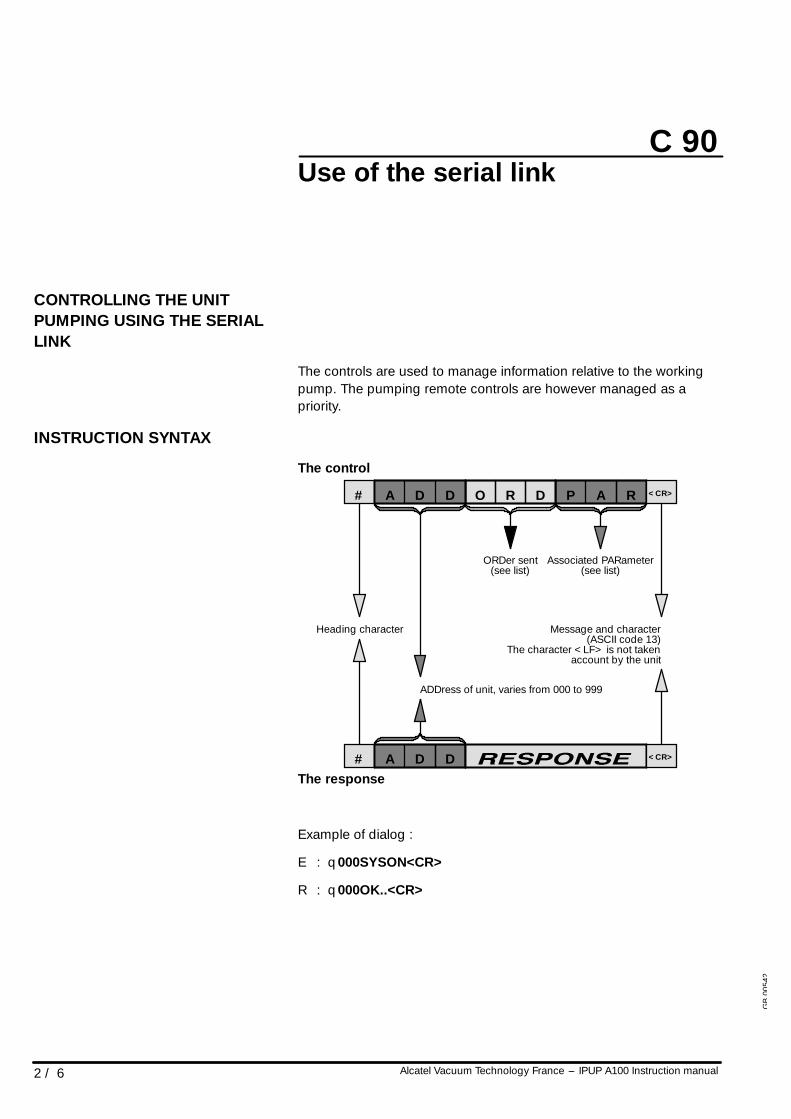
The controls are used to manage information relative to the workingpump. The pumping remote controls are however managed as apriority.
INSTRUCTION SYNTAX
The control
# O R D P A RA D D
ADDress of unit, varies from 000 to 999
ORDer sent Associated PARameter
<CR>
# A D D <CR>
(see list) (see list)
Heading character Message and character(ASCII code 13)
The character <LF> is not takenaccount by the unit
The response
Example of dialog :
E : q000SYSON<CR>
R : q000OK..<CR>
GB
0054
2
C 90
3 / 6Alcatel Vacuum Technology France --- IPUP A100 Instruction manual
Use of the serial link
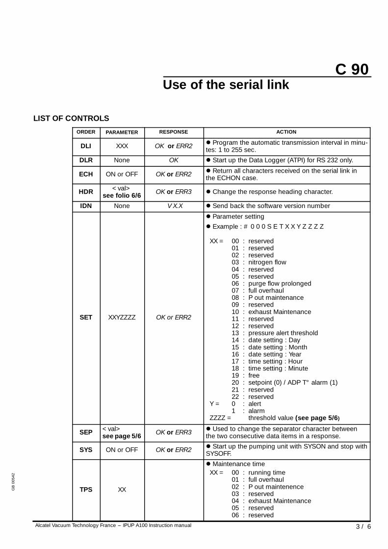
LIST OF CONTROLS
ORDER PARAMETER RESPONSE ACTION
DLI XXX OK or ERR2 l Program the automatic transmission interval in minu-tes: 1 to 255 sec.
DLR None OK l Start up the Data Logger (ATPI) for RS 232 only.
ECH ON or OFF OK or ERR2 l Return all characters received on the serial link inthe ECHON case.
HDR <val>see folio 6/6 OK or ERR3 l Change the response heading character.
IDN None V X.X l Send back the software version number
SET XXYZZZZ OK or ERR2
l Parameter settingl Example : # 0 0 0 S E T X X Y Z Z Z Z
XX = 00 : reserved01 : reserved02 : reserved03 : nitrogen flow04 : reserved05 : reserved06 : purge flow prolonged07 : full overhaul08 : P out maintenance09 : reserved10 : exhaust Maintenance11 : reserved12 : reserved13 : pressure alert threshold14 : date setting : Day15 : date setting : Month16 : date setting : Year17 : time setting : Hour18 : time setting : Minute19 : free20 : setpoint (0) / ADP T° alarm (1)21 : reserved22 : reserved
Y = 0 : alert1 : alarm
ZZZZ = threshold value (see page 5/6)
SEP <val>see page 5/6 OK or ERR3 l Used to change the separator character between
the two consecutive data items in a response.
SYS ON or OFF OK or ERR2 l Start up the pumping unit with SYSON and stop withSYSOFF.
TPS XX
l Maintenance timeXX = 00 : running time
01 : full overhaul02 : P out maintenence03 : reserved04 : exhaust Maintenance05 : reserved06 : reserved
GB
0054
2
C 90
4 / 6 Alcatel Vacuum Technology France --- IPUP A100 Instruction manual
Use of the serial link
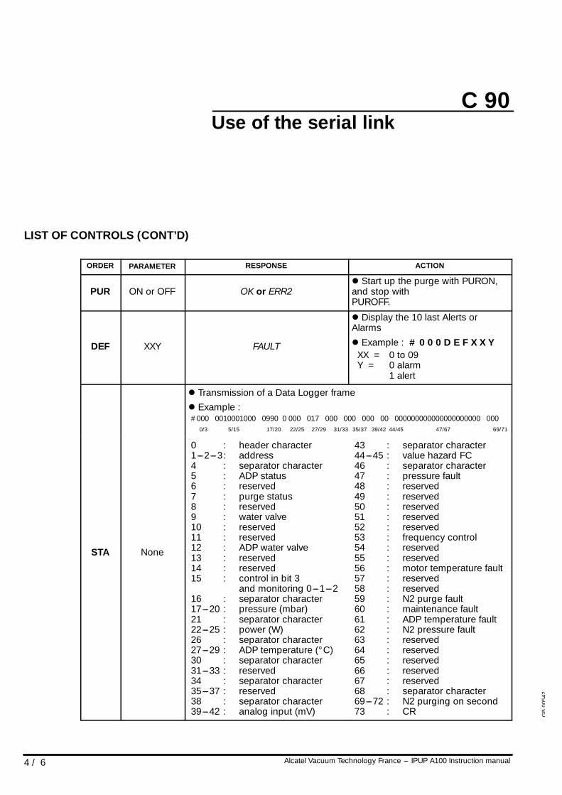
LIST OF CONTROLS (CONT’D)
ORDER PARAMETER RESPONSE ACTION
PUR ON or OFF OK or ERR2l Start up the purge with PURON,and stop withPUROFF.
DEF XXY FAULT
l Display the 10 last Alerts orAlarmsl Example : # 0 0 0 D E F X X Y
XX = 0 to 09Y = 0 alarm
1 alert
l Transmission of a Data Logger framel Example :#000 0010001000 0990 0 000 017 000 000 000 00 000000000000000000000 000
0/3 5/15 17/20 22/25 27/29 31/33 35/37 39/42 44/45 47/67 69/71
STA None
0 : header character1---2---3: address4 : separator character5 : ADP status6 : reserved7 : purge status8 : reserved9 : water valve10 : reserved11 : reserved12 : ADP water valve13 : reserved14 : reserved15 : control in bit 3
and monitoring 0---1---216 : separator character17---20 : pressure (mbar)21 : separator character22---25 : power (W)26 : separator character27---29 : ADP temperature (° C)30 : separator character31---33 : reserved34 : separator character35---37 : reserved38 : separator character39---42 : analog input (mV)
43 : separator character44---45 : value hazard FC46 : separator character47 : pressure fault48 : reserved49 : reserved50 : reserved51 : reserved52 : reserved53 : frequency control54 : reserved55 : reserved56 : motor temperature fault57 : reserved58 : reserved59 : N2 purge fault60 : maintenance fault61 : ADP temperature fault62 : N2 pressure fault63 : reserved64 : reserved65 : reserved66 : reserved67 : reserved68 : separator character69---72 : N2 purging on second73 : CR G
B00
542
C 90
5 / 6Alcatel Vacuum Technology France --- IPUP A100 Instruction manual
Use of the serial link
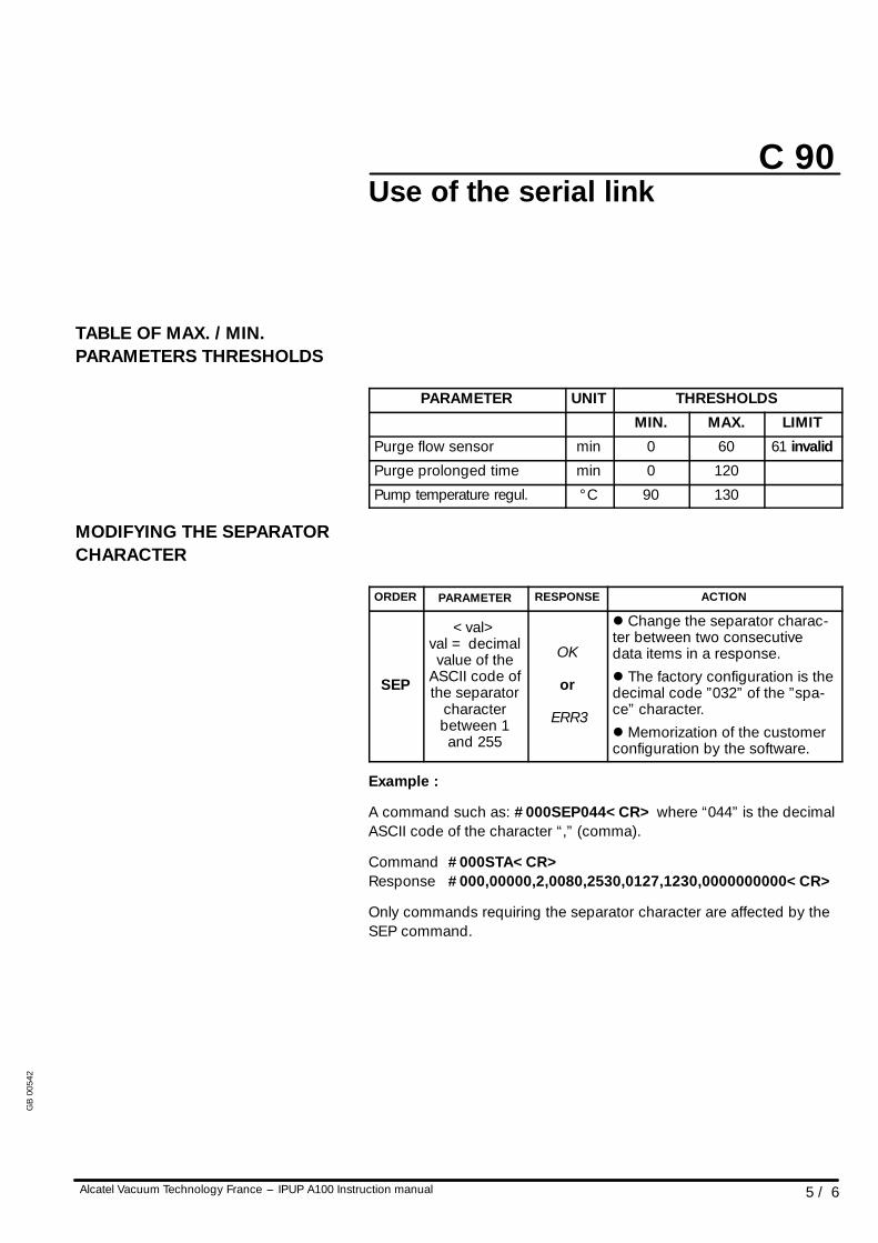
TABLE OF MAX. / MIN.PARAMETERS THRESHOLDS
PARAMETER UNIT THRESHOLDS
MIN. MAX. LIMIT
Purge flow sensor min 0 60 61 invalid
Purge prolonged time min 0 120
Pump temperature regul. ° C 90 130
MODIFYING THE SEPARATORCHARACTER
ORDER PARAMETER RESPONSE ACTION
SEP
<val>val = decimalvalue of the
ASCII code ofthe separator
characterbetween 1and 255
OK
or
ERR3
l Change the separator charac-ter between two consecutivedata items in a response.l The factory configuration is thedecimal code ”032” of the ”spa-ce” character.l Memorization of the customerconfiguration by the software.
Example :
A command such as: #000SEP044<CR> where “044” is the decimalASCII code of the character “,” (comma).
Command #000STA<CR>Response #000,00000,2,0080,2530,0127,1230,0000000000<CR>
Only commands requiring the separator character are affected by theSEP command.
GB
0054
2
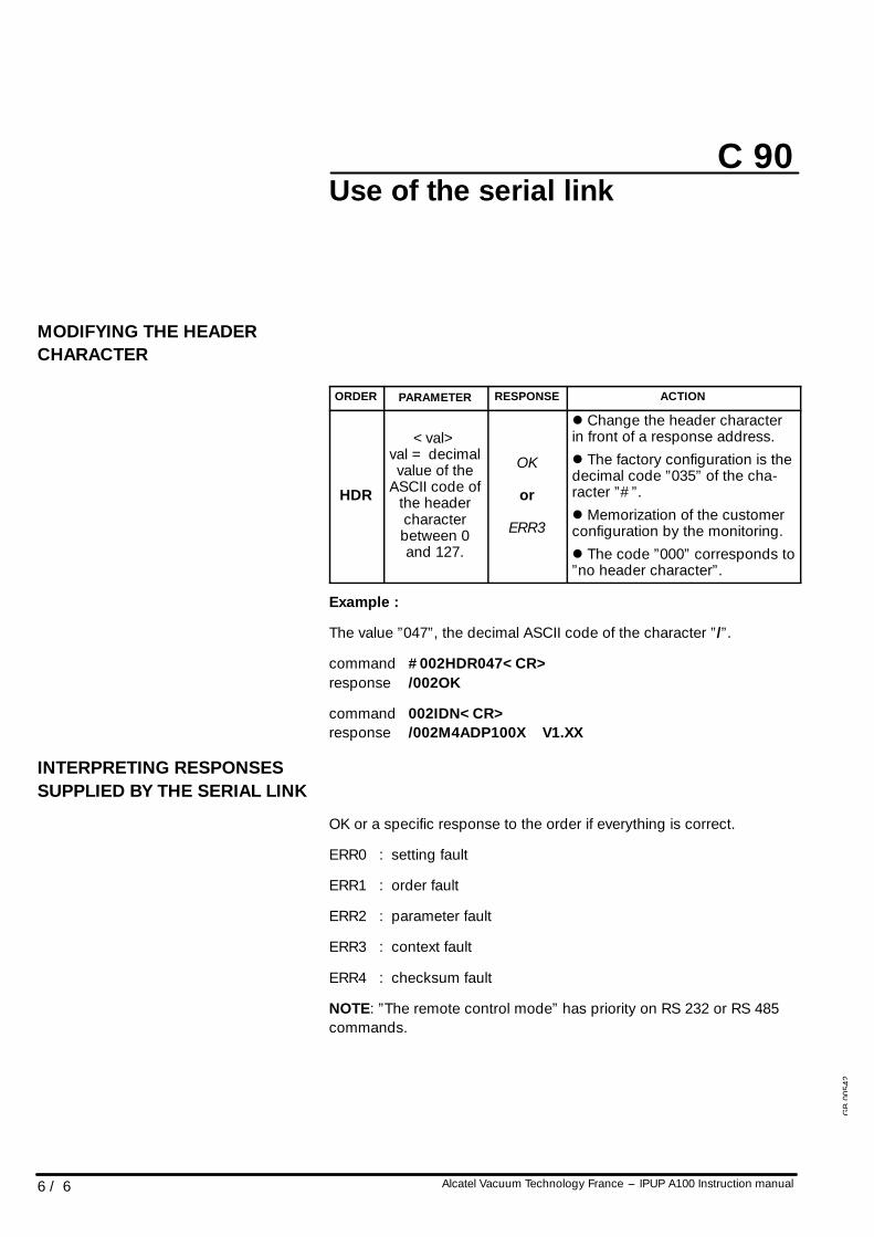
C 90
6 / 6 Alcatel Vacuum Technology France --- IPUP A100 Instruction manual
Use of the serial link
MODIFYING THE HEADERCHARACTER
ORDER PARAMETER RESPONSE ACTION
HDR
<val>val = decimalvalue of the
ASCII code ofthe headercharacterbetween 0and 127.
OK
or
ERR3
l Change the header characterin front of a response address.l The factory configuration is thedecimal code ”035” of the cha-racter ”#”.l Memorization of the customerconfiguration by the monitoring.l The code ”000” corresponds to”no header character”.
Example :
The value ”047”, the decimal ASCII code of the character ”/”.
command #002HDR047<CR>response /002OK
command 002IDN<CR>response /002M4ADP100X V1.XX
INTERPRETING RESPONSESSUPPLIED BY THE SERIAL LINK
OK or a specific response to the order if everything is correct.
ERR0 : setting fault
ERR1 : order fault
ERR2 : parameter fault
ERR3 : context fault
ERR4 : checksum fault
NOTE: ”The remote control mode” has priority on RS 232 or RS 485commands.
GB
0054
2
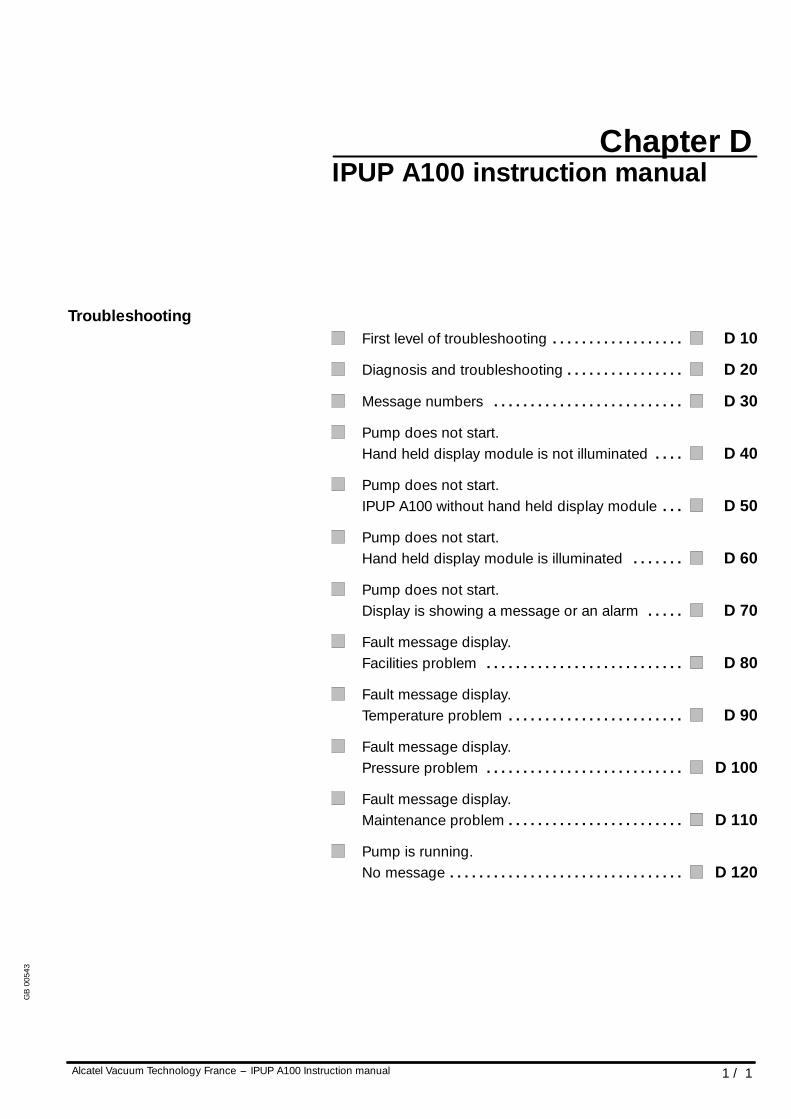
Chapter D
Alcatel Vacuum Technology France --- IPUP A100 Instruction manual 1 / 1
IPUP A100 instruction manual
TroubleshootingFirst level of troubleshooting D 10. . . . . . . . . . . . . . . . . .
Diagnosis and troubleshooting D 20. . . . . . . . . . . . . . . .
Message numbers D 30. . . . . . . . . . . . . . . . . . . . . . . . . .
Pump does not start.Hand held display module is not illuminated D 40. . . .
Pump does not start.IPUP A100 without hand held display module D 50. . .
Pump does not start.Hand held display module is illuminated D 60. . . . . . .
Pump does not start.Display is showing a message or an alarm D 70. . . . .
Fault message display.Facilities problem D 80. . . . . . . . . . . . . . . . . . . . . . . . . . .
Fault message display.Temperature problem D 90. . . . . . . . . . . . . . . . . . . . . . . .
Fault message display.Pressure problem D 100. . . . . . . . . . . . . . . . . . . . . . . . . . .
Fault message display.Maintenance problem D 110. . . . . . . . . . . . . . . . . . . . . . . .
Pump is running.No message D 120. . . . . . . . . . . . . . . . . . . . . . . . . . . . . . . .
GB
0054
3
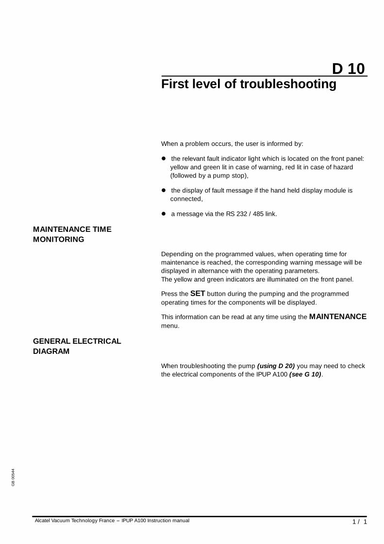
D 10
1 / 1Alcatel Vacuum Technology France --- IPUP A100 Instruction manual
First level of troubleshooting
When a problem occurs, the user is informed by:
l the relevant fault indicator light which is located on the front panel:yellow and green lit in case of warning, red lit in case of hazard(followed by a pump stop),
l the display of fault message if the hand held display module isconnected,
l a message via the RS 232 / 485 link.
MAINTENANCE TIMEMONITORING
Depending on the programmed values, when operating time formaintenance is reached, the corresponding warning message will bedisplayed in alternance with the operating parameters.The yellow and green indicators are illuminated on the front panel.
Press the SET button during the pumping and the programmedoperating times for the components will be displayed.
This information can be read at any time using the MAINTENANCEmenu.
GENERAL ELECTRICALDIAGRAM
When troubleshooting the pump (using D 20) you may need to checkthe electrical components of the IPUP A100 (see G 10).
GB
0054
4
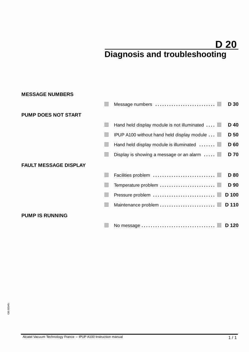
D 20
1 / 1Alcatel Vacuum Technology France --- IPUP A100 Instruction manual
Diagnosis and troubleshooting
MESSAGE NUMBERS
Message numbers D 30. . . . . . . . . . . . . . . . . . . . . . . . . .
PUMP DOES NOT START
Hand held display module is not illuminated D 40. . . .
IPUP A100 without hand held display module D 50. . .
Hand held display module is illuminated D 60. . . . . . .
Display is showing a message or an alarm D 70. . . . .
FAULT MESSAGE DISPLAY
Facilities problem D 80. . . . . . . . . . . . . . . . . . . . . . . . . . .
Temperature problem D 90. . . . . . . . . . . . . . . . . . . . . . . .
Pressure problem D 100. . . . . . . . . . . . . . . . . . . . . . . . . . .
Maintenance problem D 110. . . . . . . . . . . . . . . . . . . . . . . .
PUMP IS RUNNING
No message D 120. . . . . . . . . . . . . . . . . . . . . . . . . . . . . . . .
GB
0054
5
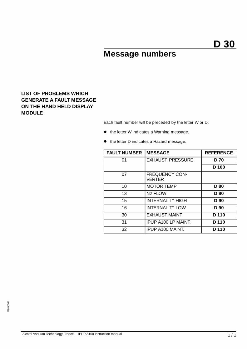
D 30
1 / 1Alcatel Vacuum Technology France --- IPUP A100 Instruction manual
Message numbers
LIST OF PROBLEMS WHICHGENERATE A FAULT MESSAGEON THE HAND HELD DISPLAYMODULE
Each fault number will be preceded by the letter W or D:
l the letter W indicates a Warning message.
l the letter D indicates a Hazard message.
FAULT NUMBER MESSAGE REFERENCE01 EXHAUST. PRESSURE D 7001 EXHAUST. PRESSURE
D 10007 FREQUENCY CON-
VERTER10 MOTOR TEMP D 8013 N2 FLOW D 8015 INTERNAL T° HIGH D 9016 INTERNAL T° LOW D 9030 EXHAUST MAINT. D 11031 IPUP A100 LP MAINT. D 11032 IPUP A100 MAINT. D 110
GB
0054
6
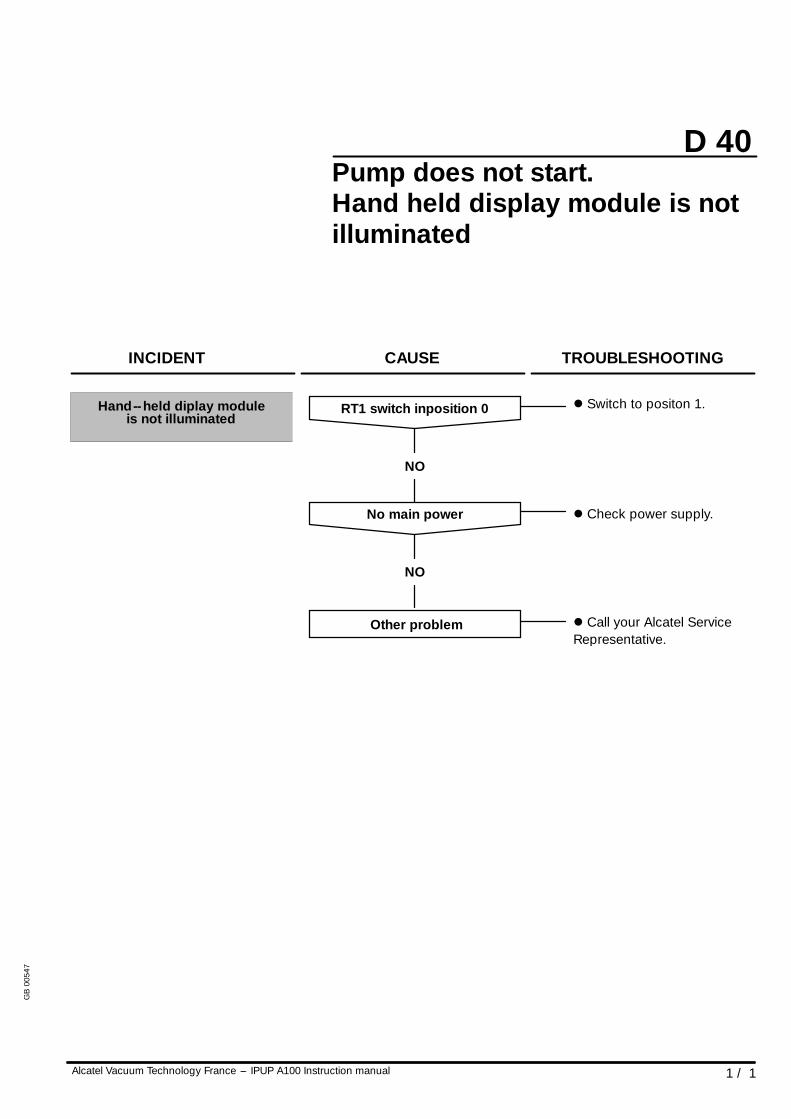
D 40
1 / 1Alcatel Vacuum Technology France --- IPUP A100 Instruction manual
Pump does not start.Hand held display module is notilluminated
NO
RT1 switch inposition 0 l Switch to positon 1.Hand--held diplay moduleis not illuminated
INCIDENT CAUSE TROUBLESHOOTING
NO
No main power l Check power supply.
Other problem l Call your Alcatel ServiceRepresentative.
GB
0054
7
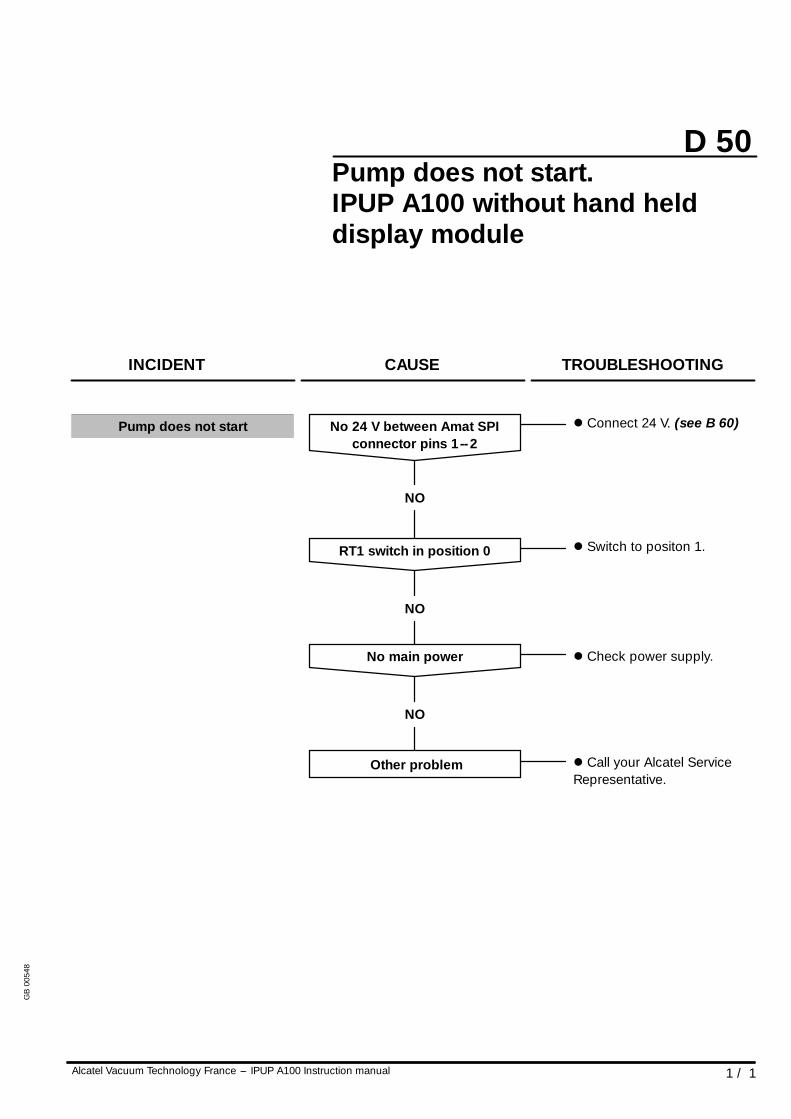
D 50
1 / 1Alcatel Vacuum Technology France --- IPUP A100 Instruction manual
Pump does not start.IPUP A100 without hand helddisplay module
NO
No 24 V between Amat SPIconnector pins 1--2
l Connect 24 V. (see B 60)
INCIDENT CAUSE TROUBLESHOOTING
NO
No main power l Check power supply.
NO
RT1 switch in position 0 l Switch to positon 1.
Other problem l Call your Alcatel ServiceRepresentative.
Pump does not start
GB
0054
8
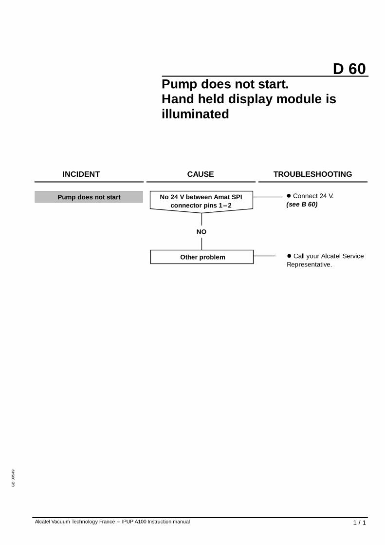
D 60
1 / 1Alcatel Vacuum Technology France --- IPUP A100 Instruction manual
Pump does not start.Hand held display module isilluminated
NO
INCIDENT CAUSE TROUBLESHOOTING
No 24 V between Amat SPIconnector pins 1--2
l Connect 24 V.(see B 60)
Other problem l Call your Alcatel ServiceRepresentative.
Pump does not start
GB
0054
9
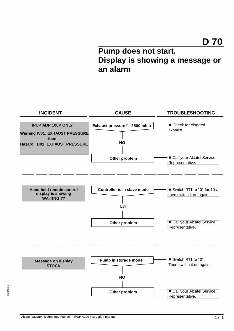
D 70
1 / 1Alcatel Vacuum Technology France --- IPUP A100 Instruction manual
Pump does not start.Display is showing a message oran alarm
Warningthen
Hazard D01: EXHAUST PRESSURE
W01: EXHAUST PRESSURE
NO
Hand held remote controldisplay is showing
Message on displaySTOCK
WAITING ??
INCIDENT CAUSE TROUBLESHOOTING
NO
Exhaust pressure ² 2500 mbar l Check for cloggedexhaust
Other problem l Call your Alcatel ServiceRepresentative.
NO
Controller is in slave mode l Switch RT1 to ”0” for 10s,then switch it on again.
Other problem l Call your Alcatel ServiceRepresentative.
NO
Pump in storage mode l Switch RT1 to ”0”.Then switch it on again.
Other problem l Call your Alcatel ServiceRepresentative.
IPUP ADP 100P ONLY
GB
0055
0
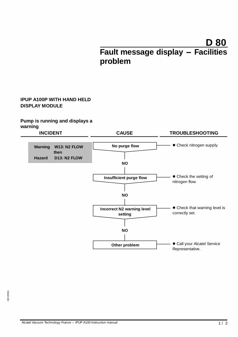
D 80
1 / 2Alcatel Vacuum Technology France --- IPUP A100 Instruction manual
Fault message display --- Facilitiesproblem
IPUP A100P WITH HAND HELDDISPLAY MODULE
Pump is running and displays awarning
Warningthen
INCIDENT CAUSE TROUBLESHOOTING
NO
No purge flow l Check nitrogen supply.
NO
Insufficient purge flow l Check the setting ofnitrogen flow.
Other problem l Call your Alcatel ServiceRepresentative.
Hazard D13: N2 FLOW
W13: N2 FLOW
NO
Incorrect N2 warning levelsetting
l Check that warning level iscorrectly set.
GB
0055
1
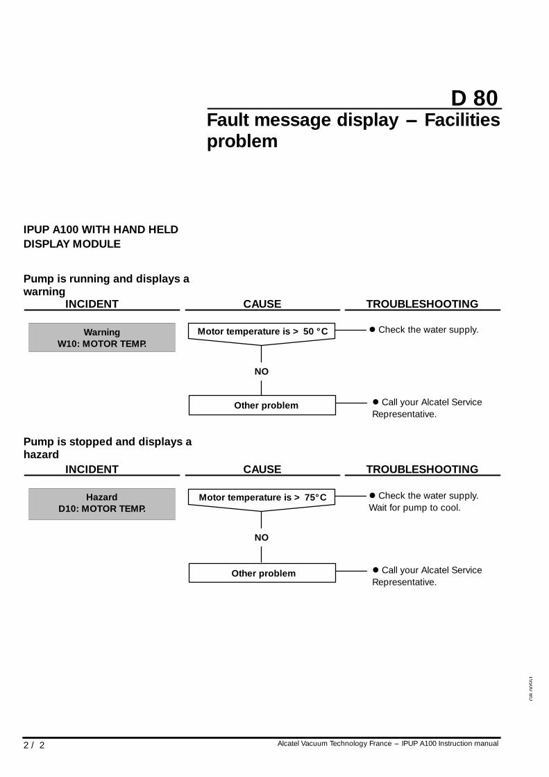
D 80
2 / 2 Alcatel Vacuum Technology France --- IPUP A100 Instruction manual
Fault message display --- Facilitiesproblem
IPUP A100 WITH HAND HELDDISPLAY MODULE
Pump is running and displays awarning
NO
Motor temperature is > 50 ° CWarningW10: MOTOR TEMP.
INCIDENT CAUSE TROUBLESHOOTING
Other problem l Call your Alcatel ServiceRepresentative.
l Check the water supply.
Pump is stopped and displays ahazard
HazardD10: MOTOR TEMP.
INCIDENT CAUSE TROUBLESHOOTING
NO
Motor temperature is > 75° C l Check the water supply.Wait for pump to cool.
Other problem l Call your Alcatel ServiceRepresentative.
GB
0055
1
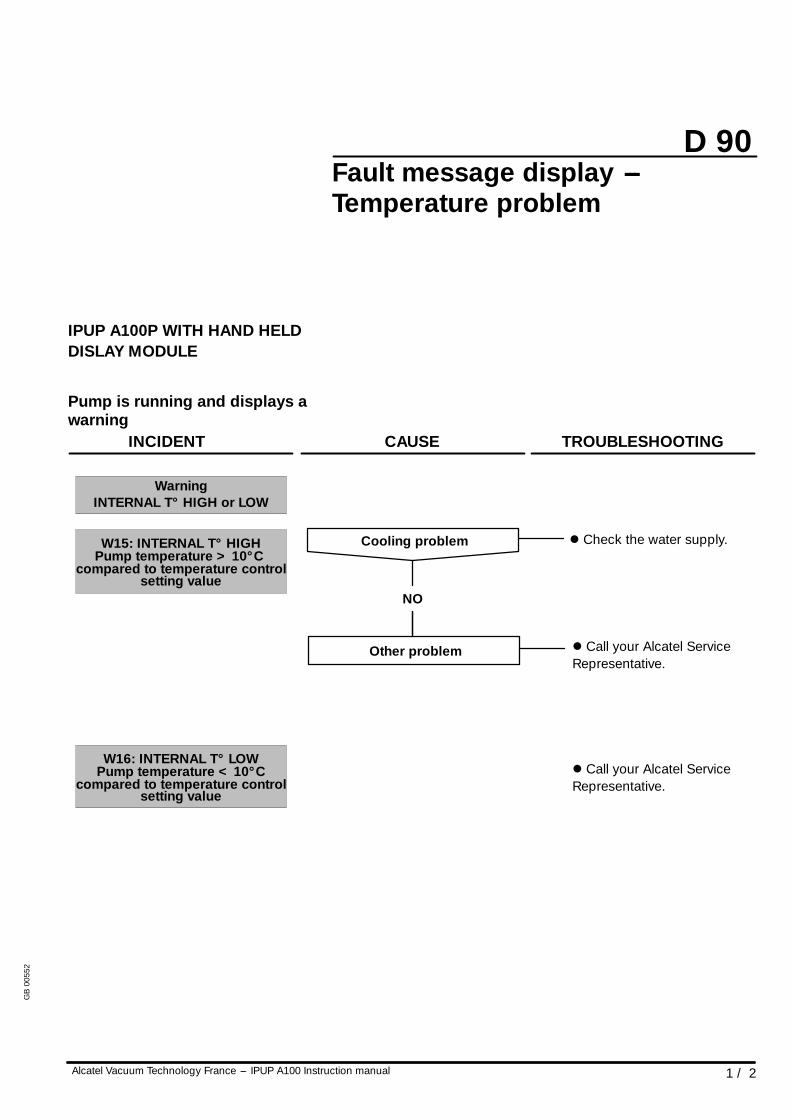
D 90
1 / 2Alcatel Vacuum Technology France --- IPUP A100 Instruction manual
Fault message display ---Temperature problem
IPUP A100P WITH HAND HELDDISLAY MODULE
Pump is running and displays awarning
l Check the water supply.W15: INTERNAL T° HIGH
Pump temperature < 10° Ccompared to temperature control
Pump temperature > 10° Ccompared to temperature control
WarningINTERNAL T° HIGH or LOW
INCIDENT CAUSE TROUBLESHOOTING
NO
Cooling problem
l Call your Alcatel ServiceRepresentative.
setting value
setting value
W16: INTERNAL T° LOW
Other problem l Call your Alcatel ServiceRepresentative.
GB
0055
2
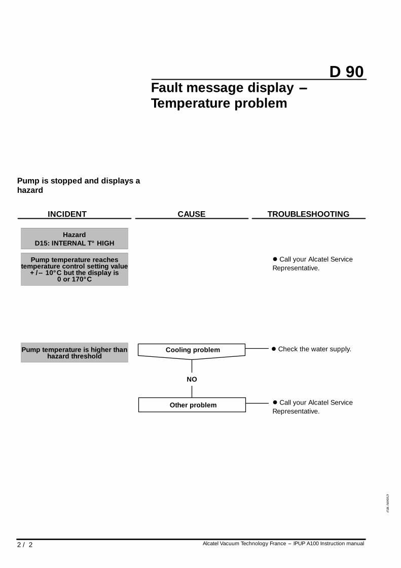
D 90
2 / 2 Alcatel Vacuum Technology France --- IPUP A100 Instruction manual
Fault message display ---Temperature problem
Pump is stopped and displays ahazard
l Check the water supply.Pump temperature is higher thanhazard threshold
Pump temperature reachestemperature control setting value
HazardD15: INTERNAL T° HIGH
+/-- 10° C but the display is0 or 170° C
INCIDENT CAUSE TROUBLESHOOTING
l Call your Alcatel ServiceRepresentative.
NO
Cooling problem
Other problem l Call your Alcatel ServiceRepresentative.
GB
0055
2
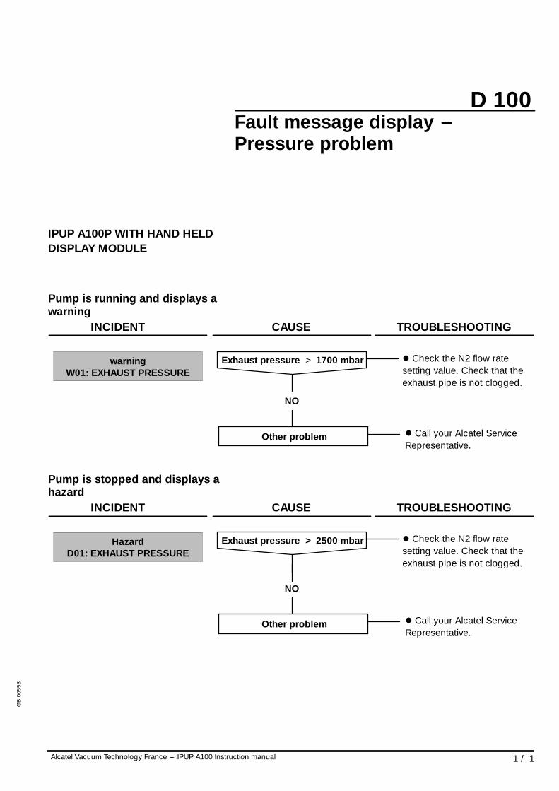
D 100
1 / 1Alcatel Vacuum Technology France --- IPUP A100 Instruction manual
Fault message display ---Pressure problem
IPUP A100P WITH HAND HELDDISPLAY MODULE
Pump is running and displays awarning
warningW01: EXHAUST PRESSURE
INCIDENT CAUSE TROUBLESHOOTING
NO
Exhaust pressure > 1700 mbar l Check the N2 flow ratesetting value. Check that theexhaust pipe is not clogged.
Other problem l Call your Alcatel ServiceRepresentative.
Pump is stopped and displays ahazard
HazardD01: EXHAUST PRESSURE
INCIDENT CAUSE TROUBLESHOOTING
NO
Exhaust pressure > 2500 mbar l Check the N2 flow ratesetting value. Check that theexhaust pipe is not clogged.
Other problem l Call your Alcatel ServiceRepresentative.
GB
0055
3
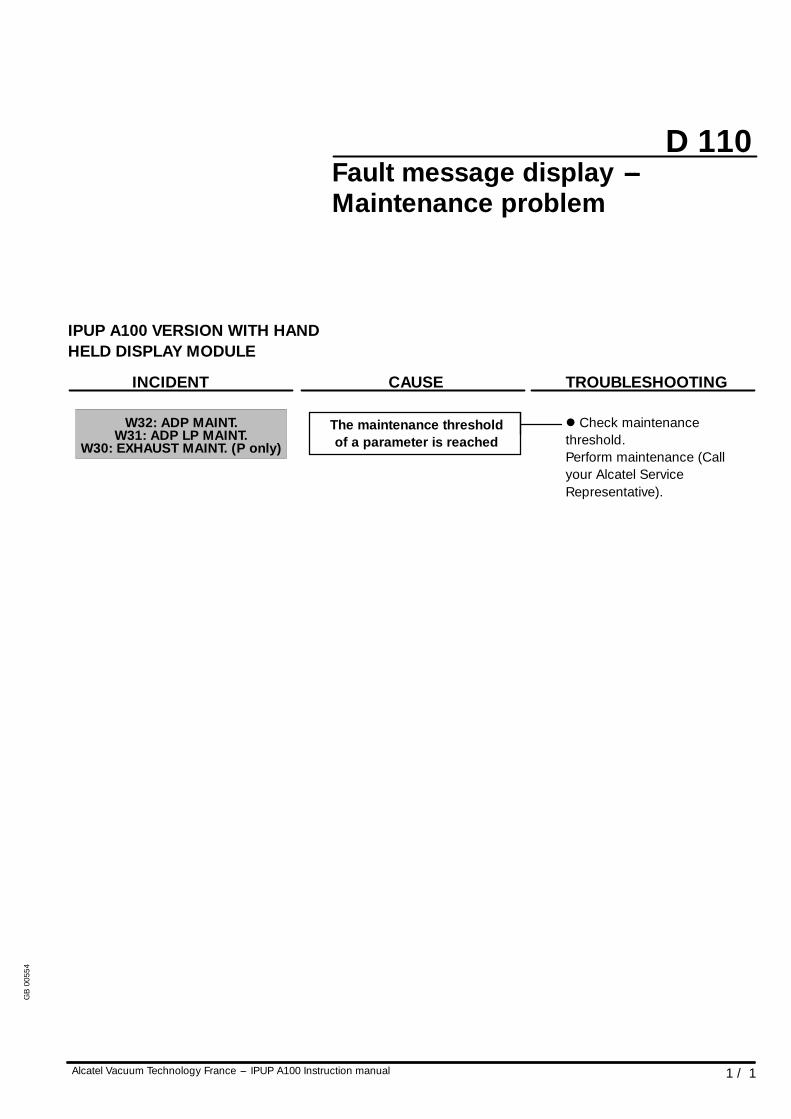
D 110
1 / 1Alcatel Vacuum Technology France --- IPUP A100 Instruction manual
Fault message display ---Maintenance problem
IPUP A100 VERSION WITH HANDHELD DISPLAY MODULE
W32: ADP MAINT.W31: ADP LP MAINT.
W30: EXHAUST MAINT. (P only)
INCIDENT CAUSE TROUBLESHOOTING
The maintenance thresholdof a parameter is reached
l Check maintenancethreshold.Perform maintenance (Callyour Alcatel ServiceRepresentative).
GB
0055
4
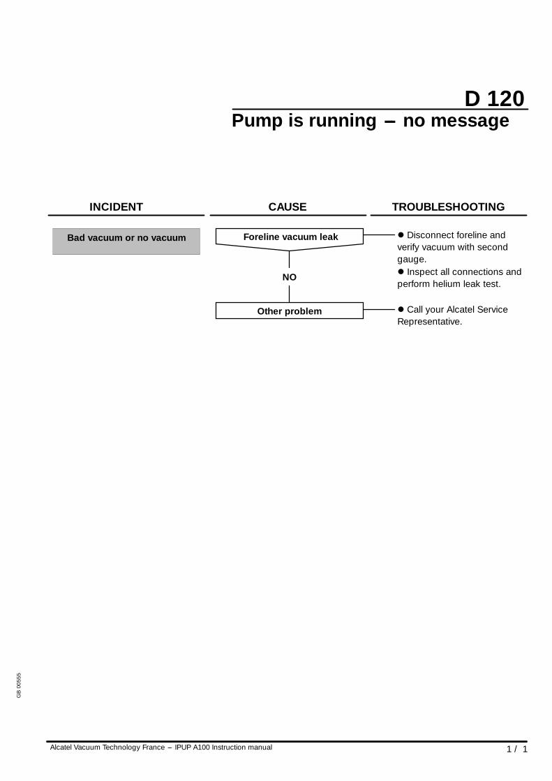
D 120
1 / 1Alcatel Vacuum Technology France --- IPUP A100 Instruction manual
Pump is running --- no message
Bad vacuum or no vacuum
INCIDENT CAUSE TROUBLESHOOTING
Other problem l Call your Alcatel ServiceRepresentative.
NO
Foreline vacuum leak l Disconnect foreline andverify vacuum with secondgauge.l Inspect all connections andperform helium leak test.
GB
0055
5
Chapter E
Alcatel Vacuum Technology France --- IPUP A100 Instruction manual 1 / 1
IPUP A100 instruction manual
Maintenance instructionsMaintenance frequency E 10. . . . . . . . . . . . . . . . . . . .
Shipping procedure for contaminated pumps E 20. .
GB
0055
6
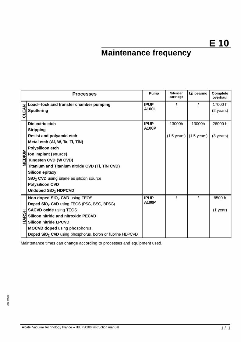
E 10
1 / 1Alcatel Vacuum Technology France --- IPUP A100 Instruction manual
Maintenance frequency
Processes Pump Silencercartridge
Lp bearing Completeoverhaul
CLE
AN Load-- lock and transfer chamber pumping
SputteringIPUPA100L
/ / 17000 h(2 years)
MED
IUM
Dielectric etchStrippingResist and polyamid etchMetal etch (Al, W, Ta, Ti, TiN)Polysilicon etchIon implant (source)Tungsten CVD (W CVD)Titanium and Titanium nitride CVD (Ti, TiN CVD)Silicon epitaxySiO2 CVD using silane as silicon sourcePolysilicon CVDUndoped SiO2 HDPCVD
IPUPA100P
13000h
(1.5 years)
13000h
(1.5 years)
26000 h
(3 years)
HA
RS
H
Non doped SiO2 CVD using TEOSDoped SiO2 CVD using TEOS (PSG, BSG, BPSG)SACVD oxide using TEOSSilicon nitride and nitroxide PECVDSilicon nitride LPCVDMOCVD doped using phosphorusDoped SiO2 CVD using phosphorus, boron or fluorine HDPCVD
IPUPA100P
/ / 8500 h
(1 year)
Maintenance times can change according to processes and equipment used.
GB
0055
7
!WARNING
!WARNING
E 20
1 / 5Alcatel Vacuum Technology France --- IPUP A100 Instruction manual
Shipping procedure forcontaminated pumps
Before shipping any pumps, remember to blow out the water line,purge the functional block with N2 and pressurize with dry nitrogen.
Remaining process gases in the pump may cause severeinjury or death.Before removing the pump, continue N2 flow from theprocess tool for 30 min. (see C 50) page 3/4 for programminginstructions.Nitrogen pressure and flow rate should be identical to theprogrammed values during process.
During pump removal, operator could be in contact withprocess residues on the exhaust which could cause severeinjury or death.Ask your safety department for instructions according to thelocal statements.
Procedure for emptying the watercircuit
As the water circuit is equipped with water valve (normaly closed),emptying operation must be done when the pump is running (sovalves are opened).
Prepare a flexible pipe (A) with a 1/4 inch quick male connector (to beconnected to compressed air circuit) and another flexible pipe (B) witha 1/4 inch female connector.
Disconnect inlet and outlet water fittings on the pump.
Connect pipe (A) on the pump, at location ”Water Out” and place theother end of the pipe in a vessel (total water volume will be less thanone litre).
Connect pipe (B) at location of ”Water In” and connect the other endto a compressed air circuit (2 to 5 bars).
When the water is filled out, quickly stop the pump and disconnectpipes (A) and (B).
D This operation must be performed quickly, because without anywater cooling the pump will overheat after a few minutes and will bein warning/hazard mode.
GB
0055
8
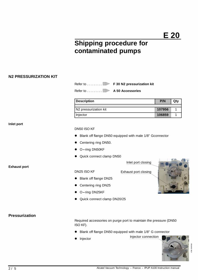
E 20
2 / 5 Alcatel Vacuum Technology --- France --- IPUP A100 Instruction manual
Shipping procedure forcontaminated pumps
N2 PRESSURIZATION KIT
Refer to F 30 N2 pressurization kit. . . . . . . . .
Refer to A 50 Accessories. . . . . . . . .
Description P/N Qty
N2 pressurization kit 107956 1
Injector 106859 1
Inlet portDN50 ISO KF
l Blank off flange DN50 equipped with male 1/8” Gconnector
l Centering ring DN50.
l O---ring DN50KF
l Quick connect clamp DN50
Exhaust portDN25 ISO KF
l Blank off flange DN25
l Centering ring DN25
l O---ring DN25KF
l Quick connect clamp DN20/25
PressurizationRequired accessories on purge port to maintain the pressure (DN50ISO KF).
l Blank off flange DN50 equipped with male 1/8” G connector
l Injector
Inlet port closing
Exhaust port closing
Injector connection
GB
0055
8
!WARNING
E 20
3 / 5Alcatel Vacuum Technology France --- IPUP A100 Instruction manual
Shipping procedure forcontaminated pumps
ROUGH DECONTAMINATIONPROCEDURE
The pump must be disconnected from its installation and isolatedelectrically.
Install the pump under a suction hood.It must remain there throughout the operation.
General sweepingFit the DN 50 blank off flange with anti---suckback valve on the inletconnector.
Sweep with dry nitrogen using the injector at an absolute pressure of1.1 to 1.5 bar for 30 minutes.
Stop the nitrogen flow.
Pressurize the pumpBlank off the outlet port.
Pressurize the pump with dry nitrogen to an absolute pressure of 1.1bar using the injector.
GB
0055
8
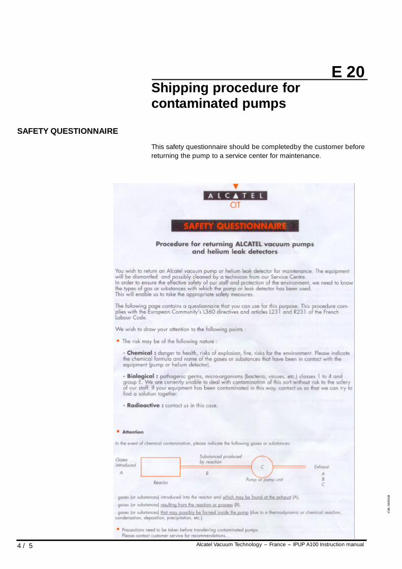
E 20
4 / 5 Alcatel Vacuum Technology --- France --- IPUP A100 Instruction manual
Shipping procedure forcontaminated pumps
SAFETY QUESTIONNAIRE
This safety questionnaire should be completedby the customer beforereturning the pump to a service center for maintenance.
GB
0055
8
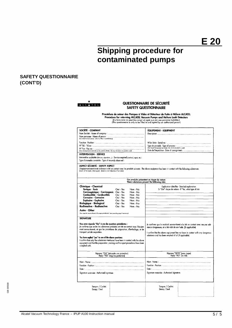
E 20
5 / 5Alcatel Vacuum Technology France --- IPUP A100 Instruction manual
Shipping procedure forcontaminated pumps
SAFETY QUESTIONNAIRE(CONT’D)
GB
0055
8
Chapter F
Alcatel Vacuum Technology France --- IPUP A100 Instruction manual 1 / 1
IPUP A100 instruction manual
Maintenance componentsN2 pressurization kit F 10. . . . . . . . . . . . . . . . . . . . . . . . .
GB
0055
9
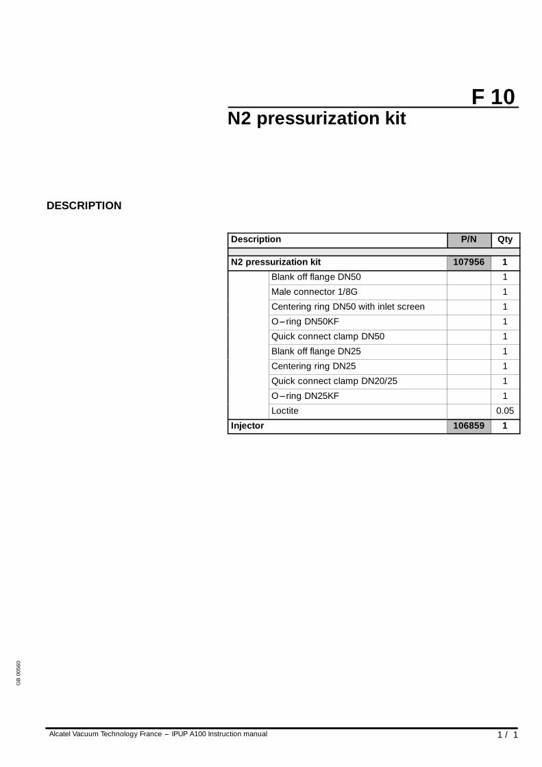
F 10
1 / 1Alcatel Vacuum Technology France --- IPUP A100 Instruction manual
N2 pressurization kit
DESCRIPTION
Description P/N Qty
N2 pressurization kit 107956 1
Blank off flange DN50 1
Male connector 1/8G 1
Centering ring DN50 with inlet screen 1
O---ring DN50KF 1
Quick connect clamp DN50 1
Blank off flange DN25 1
Centering ring DN25 1
Quick connect clamp DN20/25 1
O---ring DN25KF 1
Loctite 0.05
Injector 106859 1
GB
0056
0
Chapter G
Alcatel Vacuum Technology France --- IPUP A100 Instruction manual 1 / 1
IPUP A100 instruction manual
AppendixIPUP A100 electrical block diagram G 10. . . . . . . . . . . .
Safety data sheet G 20. . . . . . . . . . . . . . . . . . . . . . . . . . .
Accessory part numbers G 30. . . . . . . . . . . . . . . . . . . . .
GB
0056
1
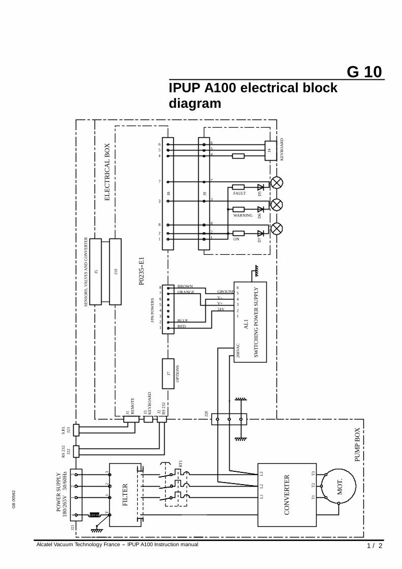
G 10
Alcatel Vacuum Technology France --- IPUP A100 Instruction manual 1 / 2
IPUP A100 electrical blockdiagram
T1T2
T3
L1L2
L3
208V
AC
1
65432
ON
WARNING
24VV+V--GROUND
FAULT
RS
232
OPT
ION
S
KEY
BO
AR
D
REM
OTE
123
REDBLUE
3
8
21
45678
ORANGEBROWN
3
8
21
7
456
7
456
12
34
12
3T
PUM
PB
OX
CO
NV
ERTE
R
SWIT
CH
ING
POW
ERSU
PPLY
D7
D6
J4
KEY
BO
AR
D
D5
RT1
FILT
ER
J2
J7
J3J1
J/P6
POW
ERS
J20
P023
5--E1
J9J8
POW
ERSU
PPLY
180/
265V
50/6
0Hz
RS
232
J22
J21
S.P.
I.J2
3
J5 J10
ELEC
TRIC
AL
BO
X
MO
T.
AL1
SEN
SOR
S,VA
LVES
AN
DC
ON
VER
TER
GB
0056
2
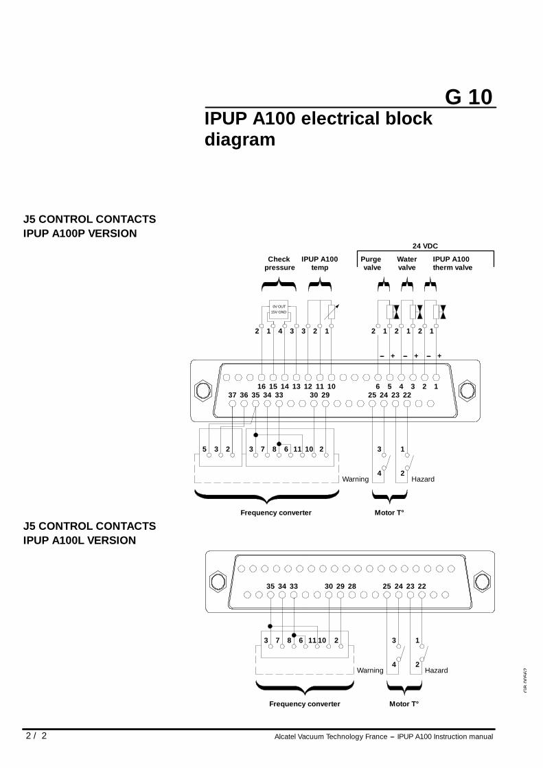
G 10
2 / 2 Alcatel Vacuum Technology France --- IPUP A100 Instruction manual
IPUP A100 electrical blockdiagram
J5 CONTROL CONTACTSIPUP A100P VERSION
625
+ --- + --- +
Watervalve
Purgevalve
IPUP A100therm valve
3 2 1222324
433 293034353637
1
Frequency converter
2
Motor T°
4 2
13283 7
1212
510111213141516
1
IPUP A100temp
233412
Checkpressure
24 VDC
---
HazardWarning
25 3
0V OUT15V GND
6 11 10
J5 CONTROL CONTACTSIPUP A100L VERSION
25 22232433 2930 283435
Frequency converter Motor T°
4 2
1321083 7
HazardWarning
6 11
GB
0056
2
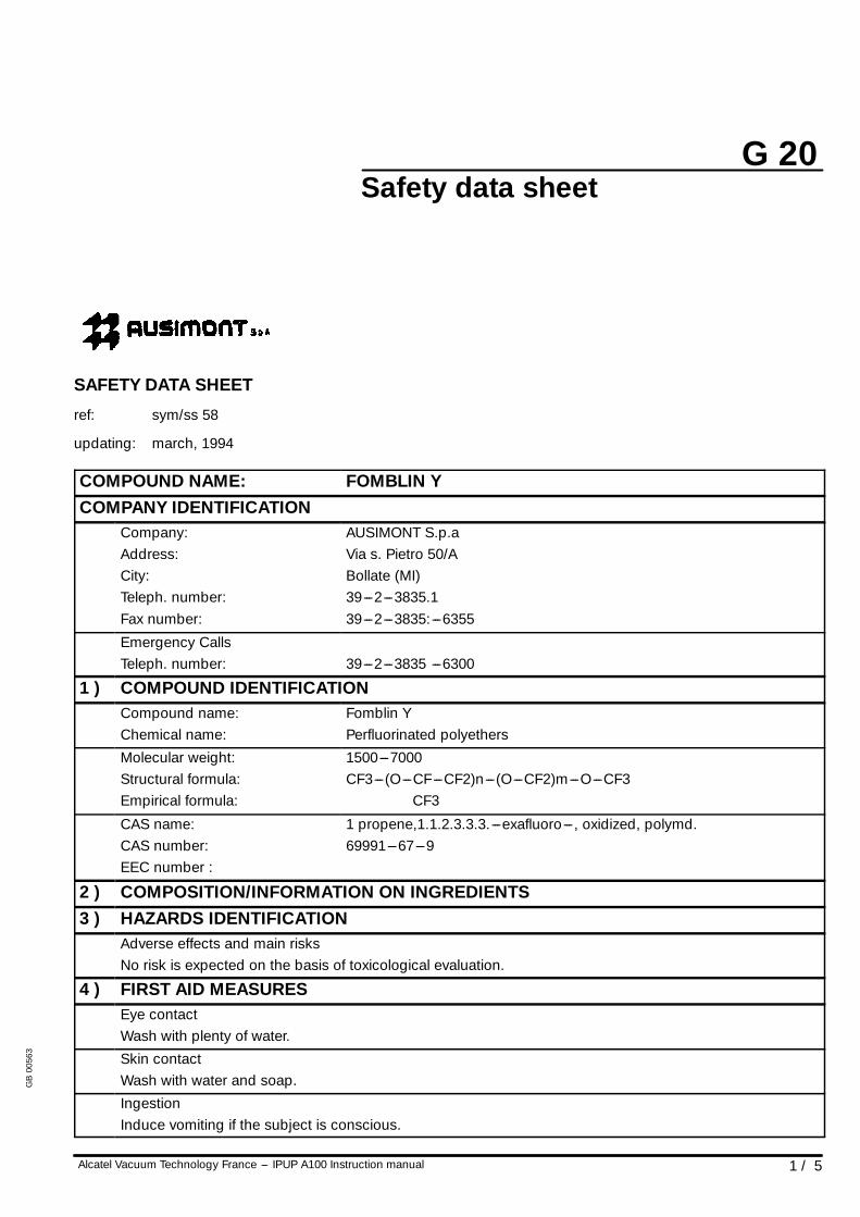
G 20
1 / 5Alcatel Vacuum Technology France --- IPUP A100 Instruction manual
Safety data sheet
SAFETY DATA SHEET
ref: sym/ss 58
updating: march, 1994
COMPOUND NAME: FOMBLIN YCOMPANY IDENTIFICATION
Company:Address:City:Teleph. number:Fax number:
AUSIMONT S.p.aVia s. Pietro 50/ABollate (MI)39---2---3835.139---2---3835:---6355
Emergency CallsTeleph. number: 39---2---3835 ---6300
1 ) COMPOUND IDENTIFICATIONCompound name:Chemical name:
Fomblin YPerfluorinated polyethers
Molecular weight:Structural formula:Empirical formula:
1500---7000CF3---(O---CF---CF2)n---(O---CF2)m---O---CF3
CF3
CAS name:CAS number:EEC number :
1 propene,1.1.2.3.3.3. ---exafluoro--- , oxidized, polymd.69991---67---9
2 ) COMPOSITION/INFORMATION ON INGREDIENTS3 ) HAZARDS IDENTIFICATION
Adverse effects and main risksNo risk is expected on the basis of toxicological evaluation.
4 ) FIRST AID MEASURESEye contactWash with plenty of water.Skin contactWash with water and soap.IngestionInduce vomiting if the subject is conscious.
GB
0056
3
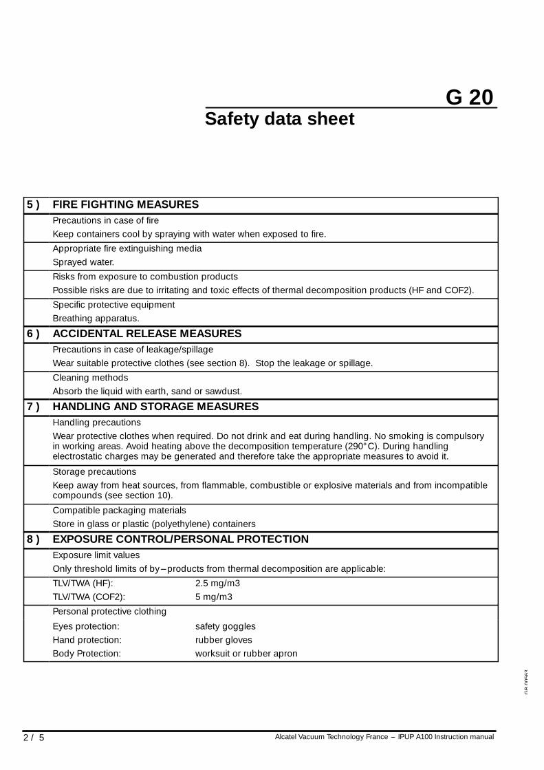
G 20
2 / 5 Alcatel Vacuum Technology France --- IPUP A100 Instruction manual
Safety data sheet
5 ) FIRE FIGHTING MEASURESPrecautions in case of fireKeep containers cool by spraying with water when exposed to fire.Appropriate fire extinguishing mediaSprayed water.Risks from exposure to combustion productsPossible risks are due to irritating and toxic effects of thermal decomposition products (HF and COF2).Specific protective equipmentBreathing apparatus.
6 ) ACCIDENTAL RELEASE MEASURESPrecautions in case of leakage/spillageWear suitable protective clothes (see section 8). Stop the leakage or spillage.Cleaning methodsAbsorb the liquid with earth, sand or sawdust.
7 ) HANDLING AND STORAGE MEASURESHandling precautionsWear protective clothes when required. Do not drink and eat during handling. No smoking is compulsoryin working areas. Avoid heating above the decomposition temperature (290° C). During handlingelectrostatic charges may be generated and therefore take the appropriate measures to avoid it.
Storage precautionsKeep away from heat sources, from flammable, combustible or explosive materials and from incompatiblecompounds (see section 10).
Compatible packaging materialsStore in glass or plastic (polyethylene) containers
8 ) EXPOSURE CONTROL/PERSONAL PROTECTIONExposure limit valuesOnly threshold limits of by---products from thermal decomposition are applicable:TLV/TWA (HF):TLV/TWA (COF2):
2.5 mg/m35 mg/m3
Personal protective clothing
Eyes protection:Hand protection:Body Protection:
safety gogglesrubber glovesworksuit or rubber apron
GB
0056
3
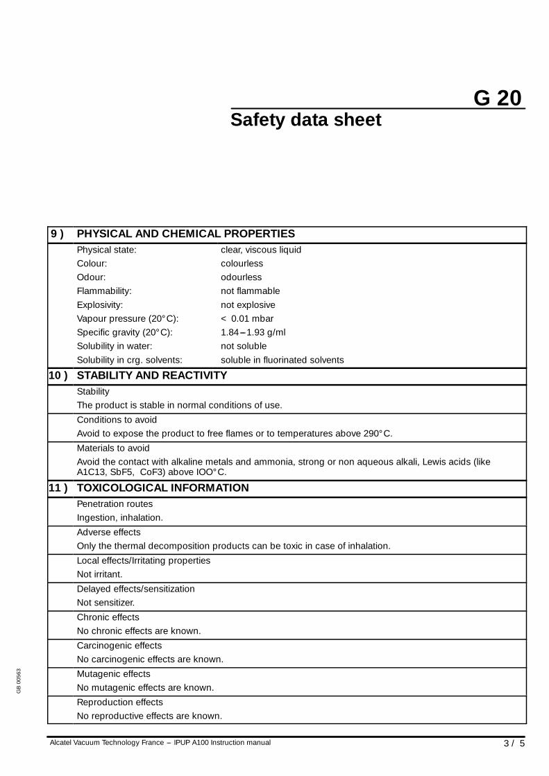
G 20
3 / 5Alcatel Vacuum Technology France --- IPUP A100 Instruction manual
Safety data sheet
9 ) PHYSICAL AND CHEMICAL PROPERTIESPhysical state:Colour:Odour:Flammability:Explosivity:Vapour pressure (20° C):Specific gravity (20° C):Solubility in water:Solubility in crg. solvents:
clear, viscous liquidcolourlessodourlessnot flammablenot explosive< 0.01 mbar1.84---1.93 g/mlnot solublesoluble in fluorinated solvents
10 ) STABILITY AND REACTIVITYStabilityThe product is stable in normal conditions of use.Conditions to avoidAvoid to expose the product to free flames or to temperatures above 290° C.Materials to avoidAvoid the contact with alkaline metals and ammonia, strong or non aqueous alkali, Lewis acids (likeA1C13, SbF5, CoF3) above IOO° C.
11 ) TOXICOLOGICAL INFORMATIONPenetration routesIngestion, inhalation.Adverse effectsOnly the thermal decomposition products can be toxic in case of inhalation.Local effects/Irritating propertiesNot irritant.Delayed effects/sensitizationNot sensitizer.Chronic effectsNo chronic effects are known.Carcinogenic effectsNo carcinogenic effects are known.Mutagenic effectsNo mutagenic effects are known.Reproduction effectsNo reproductive effects are known.
GB
0056
3
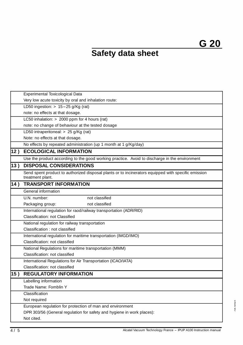
G 20
4 / 5 Alcatel Vacuum Technology France --- IPUP A100 Instruction manual
Safety data sheet
Experimental Toxicological DataVery low acute toxicity by oral and inhalation route:LD50 ingestion: > 15---25 g/Kg (rat)note: no effects at that dosage.LC50 inhalation: > 2000 ppm for 4 hours (rat)note: no change of behaviour at the tested dosageLD50 intraperitoneal: > 25 g/Kg (rat)Note: no effects at that dosage.No effects by repeated administration (up 1 month at 1 g/Kg/day)
12 ) ECOLOGICAL INFORMATIONUse the product according to the good working practice. Avoid to discharge in the environment
13 ) DISPOSAL CONSIDERATIONSSend spent product to authorized disposal plants or to incinerators equipped with specific emissiontreatment plant.
14 ) TRANSPORT INFORMATIONGeneral information
U.N. number:Packaging group:
not classifiednot classified
International regulation for raod/railway transportation (ADR/RID)Classification: not ClassifiedNational regulation for railway transportationClassification : not classifiedInternational regulation for maritime transportation (IMGD/IMO)Classification: not classifiedNational Regulations for maritime transportation (MMM)Classification: not classifiedInternational Regulations for Air Transportation (ICAO/IATA)Classification: not classified
15 ) REGULATORY INFORMATIONLabelling informationTrade Name: Fomblin YClassificationNot requiredEuropean regulation for protection of man and environmentDPR 303/56 (General regulation for safety and hygiene in work places):Not cited.
GB
0056
3
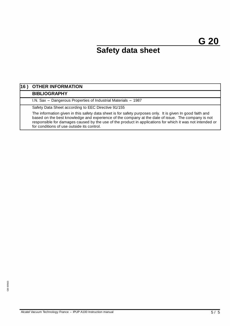
G 20
5 / 5Alcatel Vacuum Technology France --- IPUP A100 Instruction manual
Safety data sheet
16 ) OTHER INFORMATIONBIBLIOGRAPHYI.N. Sax --- Dangerous Properties of Industrial Materials --- 1987
Safety Data Sheet according to EEC Directive 91/155The information given in this safety data sheet is for safety purposes only. It is given In good faith andbased on the best knowledge and experience of the company at the date of issue. The company is notresponsible for damages caused by the use of the product in applications for which it was not intended orfor conditions of use outside its control.
GB
0056
3
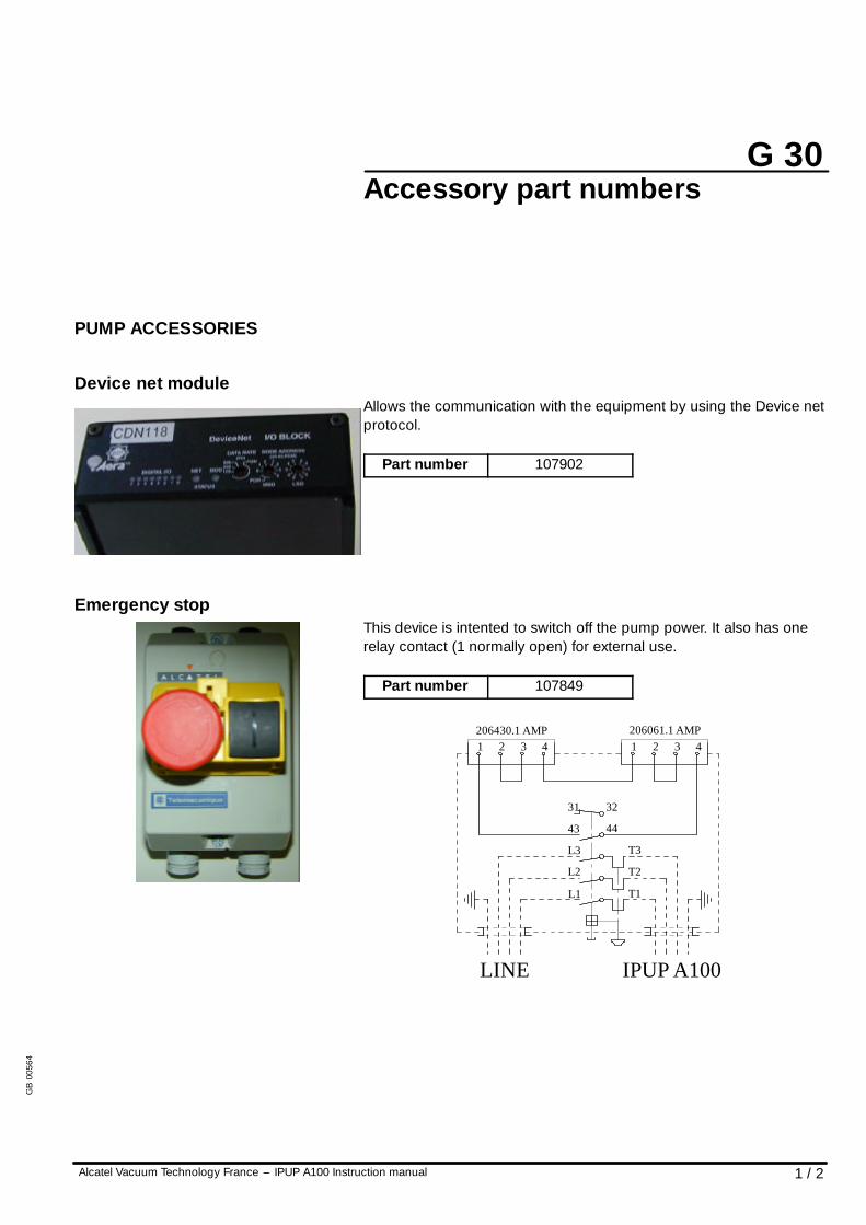
G 30
1 / 2Alcatel Vacuum Technology France --- IPUP A100 Instruction manual
Accessory part numbers
PUMP ACCESSORIES
Device net moduleAllows the communication with the equipment by using the Device netprotocol.
Part number 107902
Emergency stopThis device is intented to switch off the pump power. It also has onerelay contact (1 normally open) for external use.
Part number 107849
L1
L2
L3
43
31
T1
T2
T3
32
44
1 2 3 4206430.1 AMP
1 2 3 4206061.1 AMP
LINE IPUP A100
GB
0056
4
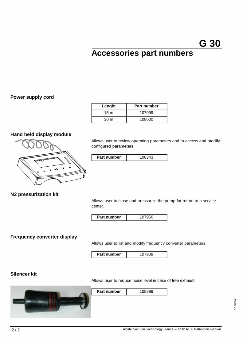
G 30
2 / 2 Alcatel Vacuum Technology France --- IPUP A100 Instruction manual
Accessories part numbers
Power supply cord
Lenght Part number
15 m 107999
30 m 108000
Hand held display moduleAllows user to review operating parameters and to access and modifyconfigured parameters.
Part number 108343
N2 pressurization kitAllows user to close and pressurize the pump for return to a servicecenter.
Part number 107956
Frequency converter displayAllows user to list and modify frequency converter parameters.
Part number 107909
Silencer kitAllows user to reduce noise level in case of free exhaust.
Part number 108599
GB
0056
4