Embed Size (px)
Citation preview

Disclosure to Promote the Right To Information
Whereas the Parliament of India has set out to provide a practical regime of right to information for citizens to secure access to information under the control of public authorities, in order to promote transparency and accountability in the working of every public authority, and whereas the attached publication of the Bureau of Indian Standards is of particular interest to the public, particularly disadvantaged communities and those engaged in the pursuit of education and knowledge, the attached public safety standard is made available to promote the timely dissemination of this information in an accurate manner to the public.
इंटरनेट मानक
“!ान $ एक न' भारत का +नम-ण”Satyanarayan Gangaram Pitroda
“Invent a New India Using Knowledge”
“प0रा1 को छोड न' 5 तरफ”Jawaharlal Nehru
“Step Out From the Old to the New”
“जान1 का अ+धकार, जी1 का अ+धकार”Mazdoor Kisan Shakti Sangathan
“The Right to Information, The Right to Live”
“!ान एक ऐसा खजाना > जो कभी च0राया नहB जा सकता है”Bhartṛhari—Nītiśatakam
“Knowledge is such a treasure which cannot be stolen”
“Invent a New India Using Knowledge”
है”ह”ह
IS/ISO 6621-2 (2003): Internal Combustion Engines - PistonRings, Part 2: Inspection Measuring Principles [TED 2:Automotive Primemovers]


IS/ISO 6621-2 : 2003(Superseding IS 12022 : 1987)
© BIS 2011
B U R E A U O F I N D I A N S T A N D A R D SMANAK BHAVAN, 9 BAHADUR SHAH ZAFAR MARG
NEW DELHI 110002
Hkkjrh; ekud
vkarfjd ngu baftu — fiLVu fjaxHkkx 2 fujh{k.k ekiu fl¼kar
Indian Standard
INTERNAL COMBUSTION ENGINES — PISTON RINGS PART 2 INSPECTION MEASURING PRINCIPLES
ICS 43.60.10
2011 Price Group 11N ovember

Automotive Primemovers, Transmission and Steering Systems and Internal Combustion EnginesSectional Committee, TED 2
NATIONAL FOREWORD
This Indian Standard (Part 2) which is identical with ISO 6621-2 : 2003 ‘Internal combustion engines —Piston rings — Part 2: Inspection measuring principles’ issued by the International Organization forStandardization (ISO) was adopted by the Bureau of Indian Standards on the recommendation of theAutomotive Primemovers, Transmission and Steering Systems and Internal Combustion EnginesSectional Committee and approval of the Transport Engineering Division Council.
This subject was first covered in IS 12022 : 1987 ‘Method of testing of quality characteristics ofpiston rings’. In order to harmonize the standard with the latest version of ISO Standard, the Committeedecided to adopt ISO Standard. With the publication of this standard IS 12022 : 1987 will be withdrawn.
The text of ISO Standard has been approved as suitable for publication as an Indian Standard withoutdeviations. Certain conventions are, however, not identical to those used in Indian Standards. Attentionis particularly drawn to the following:
a) Wherever the words ‘International Standard’ appear referring to this standard, they shouldbe read as ‘Indian Standard’.
b) Comma (,) has been used as a decimal marker while in Indian Standards, the currentpractice is to use a point (.) as the decimal marker.
In this adopted standard, reference appears to certain International Standards for which IndianStandards also exist. The corresponding Indian Standards which are to be substituted in their respectiveplaces are listed below along with their degree of equivalence for the editions indicated:
International Standard
ISO 4287 : 1997 Geometrical ProductSpecifications (GPS) — Surfacetexture: Profile method — Terms,definit ions and surface textureparameters
ISO 6621-1 : 2007 Internalcombustion engines — Piston rings— Part 1 : Vocabulary
Corresponding Indian Standard
IS 15262 : 2002 Geometrical ProductSpecifications (GPS) — Surfacetexture: Profile method — Terms,definit ions and surface textureparameters
IS/ISO 6621-1 : 2007 Internalcombustion engines — Piston rings:Part 1 Vocabulary
Degree of Equivalence
Identical
do
The technical committee has reviewed the provision of the following International Standard referredin this adopted standard and has decided that it is acceptable for use in conjunction with this standard:
International Standard Title
ISO 6507-3 Metallic material — Vickers hardness test — Part 3: Calibration of referenceblocks

1 Scope
This part of ISO 6621 specifies the principles to be used in the measuring for inspection purposes of piston rings for both reciprocating internal combustion engines and compressors working under analogous conditions. It is applicable to all such rings of a diameter u 200 mm.
2 Normative references
The following referenced documents are indispensable for the application of this document. For dated references, only the edition cited applies. For undated references, the latest edition of the referenced document (including any amendments) applies.
ISO 4287-1:1984, Surface roughness — Terminology — Part 1: Surface and its parameters
ISO 4287:1997, Geometrical Product Specifications (GPS) — Surface texture: Profile method — Terms, definitions and surface texture parameters
ISO 6507-3, Metallic materials — Vickers hardness test — Part 3: Calibration of reference blocks
ISO 6621-1, Internal combustion engines — Piston rings — Part 1: Vocabulary
3 Terms and definitions
For the purposes of this document, the terms and definitions given in ISO 6621-1 and in 4.2 apply.
4 Measuring principles
4.1 General measuring conditions
The following general conditions are applicable to all measuring principles, unless otherwise specified.
a) The ring shall rest on the reference plane in the free or open condition. No additional force shall be applied to load the ring on the reference plane, except when measuring unevenness in accordance with 4.2.19 or helix in accordance with 4.2.20.
b) Certain measurements are made with the ring in the closed condition in a gauge of nominal cylinder bore diameter. When orientated rings are measured in this way, they shall be so placed that the top side of the ring is towards the reference plane.
c) Measurements shall be made using instruments with a resolution not exceeding 10 % of the tolerance of the dimension being measured.
PART 2 INSPECTION MEASURING PRINCIPLES
INTERNAL COMBUSTION ENGINES — PISTON RINGS
Indian Standard
IS/ISO 6621-2 : 2003
1

2
4.2 Ring characteristics and their measurement
Characteristic/Definition Measuring principle/method
4.2.1 Ring width (in millimetres)
4.2.1.1 Parallel-sided rings, h1
distance between the sides at any particular point perpendicular to the reference plane measured in millimetres (see Figures 1 and 2)
Measure with spherical measuring probes, each of radius 1,5 mm ± 0,05 mm, exerting a measuring force of approximately 1 N (see Figure 3).
In the case of slotted oil rings, the measurement shall be made between the slots and not across them, i.e. across a solid portion of the ring cross section (see Figure 2).
Figure 1
Figure 2
Figure 3
4.2.1.2 Keystone rings, half-keystone rings, h3
distance between the sides at a distance a6 from the peripheral surface (see Figure 4), or, alternatively, width controlled by a6 at a specified width h3 (see Figure 6)
Method A
This method determines h3 for a specified value of a6 (see Figure 4).
Figure 4
IS/ISO 6621-2 : 2003
Characteristic/Definition Measuring principle/method
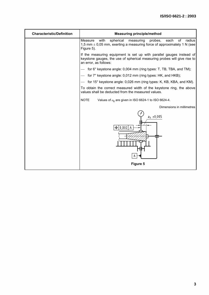
Measure with spherical measuring probes, each of radius 1,5 mm ± 0,05 mm, exerting a measuring force of approximately 1 N (seeFigure 5).
If the measuring equipment is set up with parallel gauges instead of keystone gauges, the use of spherical measuring probes will give rise to an error, as follows:
for 6° keystone angle: 0,004 mm (ring types: T, TB, TBA, and TM);
for 7° keystone angle: 0,012 mm (ring types: HK, and HKB);
for 15° keystone angle: 0,026 mm (ring types: K, KB, KBA, and KM).
To obtain the correct measured width of the keystone ring, the above values shall be deducted from the measured values.
NOTE Values of a6 are given in ISO 6624-1 to ISO 6624-4.
Dimensions in millimetres
Figure 5
IS/ISO 6621-2 : 2003
3

4
Characteristic/Definition Measuring principle/method
Method B This method determines a6 for a specified value of h3 (see Figure 4).
Measure with a flat face probe exerting a measuring force of approximately 1 N. The ring shall be placed between two sharp edged (radius u 0,01 mm) circular discs which are spaced apart at the specified gauge width h3 (see Figure 6). NOTE Values of h3 are given in ISO 6624-1 to ISO 6624-4.
Dimensions in millimetres
Figure 6
4.2.2 Radial wall thickness, a1 (in millimetres)
radial distance between the peripheral surface and the inside surface of the ring measured in millimetres (see Figure 7)
a) Measure radially between a flat measuring surface on the peripheral surface and a special measuring surface with a radius of approximately 4 mm on the bore using a measuring force of 3 N to 10 N (see Figure 8).
Figure 7
IS/ISO 6621-2 : 2003

Characteristic/Definition Measuring principle/method
Figure 8
b) Measure radially between cylindrical inserts or rollers of radius approximately 4 mm with a measuring force of 3 N to 10 N. The peripheral surface of the rollers shall be perpendicular to the reference plane.
The length of the rollers shall be greater than the axial ring width (see Figure 9).
Figure 9
4.2.3 Total free gap m, p (in millimetres)
chordal distance between the gap ends of the ring in a free unstressed state, measured at the centre line of the radial wall thickness measured in millimetres (see Figure 10); for rings with an internal notch for a peg — chordal distance marked as p in Figure 11
Measure with a steel rule to the nearest 0,25 mm.
Optionally, this feature may be measured with callipers.
Figure 10
IS/ISO 6621-2 : 2003
5

6
Characteristic/Definition Measuring principle/method
Figure 11
4.2.4 Closed gap, s1 (in millimetres)
distance between the gap ends of the ring measured at the narrowest point, which the ring would have when fitted in a gauge of nominal cylinder bore size (see Figure 12)
NOTE The closed gap s1 is related to the nominal diameter d1.
Measure in a bore gauge of nominal diameter using a wedge gauge or feeler gauges and using a measuring force of approximately 1 N (see Figure 12).
The diameter of the bore gauge shall comply with 10,001
1 0dd +
Correction shall be made for any deviation of the bore gauge from the nominal ring diameter.
Figure 12
IS/ISO 6621-2 : 2003

Characteristic/Definition Measuring principle/method
4.2.5 Tangential force, Ft (in newtons)
4.2.5.1 Single-piece rings (not recommended for rings d1 < 50 mm — see 4.2.6.)
force necessary to maintain the ring at the closed gap condition by means of a tangential pull on the ends of a circumferential metal tape or hoop (see Figures 13 and 14)
Tape method (see Figure 13)
Carry the encircling steel tape of thickness 0,08 mm to 0,10 mm around 10 mm diameter rollers set 20 mm apart (see Figure 13). In tightening the tape, close the ring to the point where the gap ends touch and then open to the closed-gap dimension previously measured. Then read off the ring force from the precision measuring scale. The gap of the ring shall be symmetrically disposed between the rollers.
An alternative method to set up the tangential loading of the force measuring instrument is using a solid disc of nominal bore diameter ± 0,005 mm to set up the length of the tape. Insert the gauge disc into the tape and adjust the tape length until the specified mean limit tangential force is indicated.
Key 1 measuring scale 2 diameter of roller = 10 mm
Figure 13
IS/ISO 6621-2 : 2003
7

8
Characteristic/Definition Measuring principle/method
Hoop method (see Figure 14)
Place the ring in a correctly sized hoop with its gap aligned to the gap of the hoop. Then close the hoop in a precision loading machine until the loading pins are at a predetermined distance apart at which point the hoop is precisely at the cylinder bore diameter appropriate to the ring (see Figure 14). Read the force from the display.
Key 1 measuring scale a Loading-pin spacing to suit machine.
Figure 14
Encircling tape method
A steel tape 0,08 mm to 0,1 mm in thickness encircles the ring crossing at the gap (see Figure 13).
The tape is tightened until the ring is closed to the closed gap previously measured. The ring force is then read off the precision measuring scale.
NOTE No vibration when measuring single-piece rings according to the three methods.
IS/ISO 6621-2 : 2003

Characteristic/Definition Measuring principle/method
4.2.5.2 Multi-piece rings
force which is necessary to maintain the ring at the closed gap condition by means of a tangential pull on the ends of a circumferential metal tape or hoop (see Figure 15)
NOTE Vibration is used to reduce friction during or prior to measurement.
For the measurement of coil-spring-loaded rings or similar rings where the spring is supported in the bore of the ring, the gap of the spring shall be positioned at 180° to the gap of the ring.
For the measurement of expander/segment oil-control rings, the ring assembly shall be mounted in a carrier simulating the piston-ring groove. The gap of the spring element shall be placed at 180° to the gap of the rails, both of which shall be in line. Choice of ring carrier type (see Table 1) to be decided between manufacturer and client.
For the measurement of a ring provided with a wavy spring, or other spring which is groove-root supported, the ring assembly shall be mounted in a carrier simulating the groove, the root diameter of which is equal to the mean diameter of the piston ring groove in which the ring will be used.
Tolerance on carrier root diameter ± 0,02 mm. The gap of the wavy spring shall be at 180° to the gap of the ring.
Key 1 measuring scale
Figure 15
Table 1 — Alternative ring carriers
Carrier groove mm
Type
Width Tolerance
I h1 + 0,01
II h1 + 0,02
III h1 + 0,03
0,020
+
where h1 = nominal ring width.
IS/ISO 6621-2 : 2003
9

10
Characteristic/Definition Measuring principle/method
Tape method with circumferential vibration
Procedures are identical to those used for single piece rings but an appropriate vibration shall be applied to the tape-loading mechanism to relieve forces of friction (see Figure 16). A suitable level is 40 Hz to 50 Hz at an amplitude of ± 0,15 mm.
Key 1 measuring scale a Vibration.
Figure 16
Encircling tape method with axial vibration
Procedures are identical to those used for the single-piece rings (encircling tape method) except that a carrier may be used and vibration (slapping) is applied to the encircled ring or encircled ring with carrier to reduce friction (see Figure 17). A suitable level of slapping is 1 to 3 times/s.
a Slapping.
Figure 17
IS/ISO 6621-2 : 2003

Characteristic/Definition Measuring principle/method
Hoop method with circumferential vibration Procedures are identical to those used for single-piece rings but an appropriate vibration shall be applied to the hoop loading mechanism to relieve all forces of friction (see Figure 18).
Key 1 measuring scale a Vibration. b Loading-pin spacing to suit machine.
Figure 18
IS/ISO 6621-2 : 2003
11

12
Characteristic/Definition Measuring principle/method
Tape or hoop method with axial vibration
Procedures are identical to those used for single-piece rings but an appropriate axial vibration shall be applied to the carrier which is simulating the ring groove to relieve forces of friction.
A suitable level of vibration is 420 Hz (≅ 25 000 cycles/min). The axial vibration shall have such an amplitude that the exerted force on the carrier will reach approximately ± 18 N (see Figure 19 — hoop method shown).
Key 1 measuring scale a Axial vibration. b Loading-pin spacing to suit machine.
Figure 19
Before tangential force measurements are made, rings shall be degreased and optionally lightly coated with thin machine oil.
Closed-gap measurements should be made immediately prior to measuring tangential force.
In order to improve consistency of measurement and particularly with coil-spring-loaded rings which have been oxided or phosphated, it is permissible to rotate the spring forwards and backwards to smooth the surface before carrying out measurements.
The manufacturer and client should agree on a suitable factor to take account of different machines, different locations and different operators.
NOTE The reproducibility of tangential-force measurements has not been high in the past but current machines using encircling tape and hoop methods give an overall reproducibility of the order of 10 %.
IS/ISO 6621-2 : 2003

Characteristic/Definition Measuring principle/method
4.2.6 Diametral force, Fd (in newtons)
force, acting diametrically at 90° to the gap, necessary to maintain the ring at the nominal diameter condition measured in the direction of the force (see Figure 20)
NOTE This method is applicable only to single-piece rings.
Measure in purpose-built machines which incorporate flat plates for closing the rings (see Figure 20).
Figure 20
4.2.7 Ovality, U (in millimetres)
difference between the mutually perpendicular diameters d3 and d4 when the ring is drawn to closed gap within a flexible tape
NOTE It may be either positive (d3 > d4) or negative (d3 < d4) (see Figure 21).
NOTE This method is applicable only to single-piece rings.
Measure with the ring drawn to its closed gap in a flexible steel tension tape or band of thickness 0,08 mm to 0,10 mm using a diametral measuring device exerting a measuring force of u 1 N (see Figure 21).
With the ring closed within the tape, it is an acceptable alternative to clamp it between plates and then remove the tape prior to measuring the diameters d3 and d4. However, clamping of the ring between plates is not applicable to oil control rings with slots.
Figure 21
IS/ISO 6621-2 : 2003
13

14
Characteristic/Definition Measuring principle/method
4.2.8 Point deflection, W (in millimetres)
deviation of the butt ends fromthe true circle when restrained in a gauge of nominal cylinder-bore diameter (see Figure 22)
Measure with a probe of spherical radius 1,5 mm ± 0,05 mm using a measuring force of approximately 1 N, with the ring mounted in a gauge of nominal cylinder-bore diameter relieved over the gauge angle, θ, (see Figure 22).
Point deflection W and the gauge angle θ shall be agreed between manufacturer and client.
The following gauge tolerances apply for this test:
angle θ : ± 1°
diameter: 10,0011 0
dd +
circularity: u 0,0001d1
Key 1 gauge
Figure 22
4.2.9 Light tightness (percentage of ring circumference)
ability of the peripheral surface of a ring when mounted in a gauge of nominal cylinder-bore diameter to exclude the passage of light (see Figure 23)
NOTE Areas of the ring showing pinpoint, burry or fuzzy light are considered light-tight.
Measure in a gauge equipped with a suitable light source and determine the percentage of the ring circumference which will allow light to pass (see Figure 23).
It is permissible to rotate the ring in the gauge to remove any slight surface roughness on the peripheral surface. Unless otherwise specified, examination and measurement should be made without magnification and with normal eyesight. It is important to avoid errors of parallax and to protect the viewer against stray light penetration.
IS/ISO 6621-2 : 2003

Characteristic/Definition Measuring principle/method
Luminance behind the ring shall be 400 lx to 1 500 lx above the ambient conditions. The following gauge tolerances apply for this test:
diameter: 10,0011 0
dd +
circularity: u 0,0001d1
Key 1 lamp
Figure 23
4.2.10 Taper on peripheral surface (in micrometres or degrees)
intentional angular deviation of the peripheral surface from a line perpendicular to the reference plane (see Figure 24)
NOTE In the case of the taper faced peripheral surface with partly cylindrical area, both measuring points have to be placed on the taper area.
Method A
Measure at the back of the ring perpendicular to the reference plane using flat faced probes exerting a force of approximately 1 N (see Figure 25).
The measurement recorded is the difference in radial dimension of the ring peripheral surface between two points, near the top and near the bottom, distance H apart. H shall be approximately two-thirds of the total axial width of the ring's peripheral surface and the recorded measurement may be converted to the taper angle in degrees or minutes.
Figure 24
IS/ISO 6621-2 : 2003
15

16
Characteristic/Definition Measuring principle/method
Figure 25
Method B
Place the ring on a reference plane and graph the peripheral surface of the back of the ring, perpendicular to the reference plane, using a profile recorder.
The magnification used shall be clearly indicated.
NOTE The same methods can be used to determine the unintentional taper which could be present on, for example, a nominally straight faced rectangular ring.
4.2.11 Barrel on peripheral surface, t2, t3 (in millimetres)
intentional convex deviation of the peripheral surface from a line perpendicular to the reference plane (see Figure 26 for symmetrical barrel and Figure 28 for asymmetrical barrel)
Method A
Measure at the back of the ring perpendicular to the reference plane using flat-faced probes exerting a force of approximately 1 N (see Figure 27).
The measurement recorded is the difference in radial dimension of the ring peripheral surface between two points — one at the peak of the barrel (at or near the centre line of the ring), and the second at a distance h8/2 from the centreline of the nominal ring width h1.
a Reference plane.
Figure 26
IS/ISO 6621-2 : 2003

Characteristic/Definition Measuring principle/method
Figure 27
Method B
Mount the ring on a reference plane and graph the peripheral surface of the back of the ring, perpendicular to the reference plane, using a profile recorder.
The magnification used shall be clearly indicated (recommended ratio between vertical and horizontal magnifications: 10 or 25).
NOTE The same methods can be used to determine the unintentional barrel which could be present on, for example, a nominally straight-faced rectangular ring.
Gauge width (h8) is for information only.
Key 1 mark a Reference plane.
Figure 28
IS/ISO 6621-2 : 2003
17

18
Characteristic/Definition Measuring principle/method
4.2.12 Land width, h4, h5 (in millimetres)
width of the land which theoretically should be in contact with the cylinder bore (see Figure 29)
Method A
For all forms of land (sharp edge, chamfered or radiused), measure with a measuring microscope or on a projector. The measurement shall be made only on the peripheral surface of the lands (see Figure 30).
Figure 29
Figure 30
Method B
For all forms of land, place the ring on a reference plane and graph the lands on a profile recorder.
The magnification used shall be clearly stated.
NOTE Land offset (see 4.2.13) can be included and obtained from this measurement at the back of the ring.
4.2.13 Land offset (in millimetres)
displacement of the two peripheral surfaces of a slotted or drilled oil control ring in relation to each other in a radial direction (see Figure 31)
Method A
Measure at the back of the ring from a line perpendicular to the reference plane (see Figure 31) using flat measuring probes exerting a force of approximately 1 N. The ring shall be loaded against the measuring instrument in the direction of and in the position of the force F (see Figure 32). The value of force F shall be in the range of 3 N to 5 N.
Figure 31
IS/ISO 6621-2 : 2003

Characteristic/Definition Measuring principle/method
Figure 32
Method B See 4.2.12, Method B.
4.2.14 Plating/coating thickness (in millimetres)
distance between the outer surface of the plating/coating and the surface of the base ring material connected with the different configurations of platings/coatings (see Figure 33)
Measure non-destructively in the middle of the width of plating/coating using a calibrated inductive thickness-measuring instrument. The calibration shall be made using a master ring being tested.
Suggested points for measuring are at the back of the ring and at 15 mm from each gap end.
The plating/coating thickness shall comply with the specification at any particular point of the peripheral surface.
a) fully faced
b) inlaid
c) semi-inlaid
Figure 33
IS/ISO 6621-2 : 2003
19

20
Characteristic/Definition Measuring principle/method
4.2.15 Nitrided case depth (in millimetres)
thickness of the surface layer with a hardness value W 700 HV 0,1 measured perpendicular to thering peripheral surface or side faces
Measure on prepared cross sections of the ring. Measure the micro-hardness HV 0,1 at various distances from the peripheral or side face surfaces. Recommended increments are 0,01/0,015/0,02.
The hardness values should be plotted against the perpendicular distance from the surface and the hardness characteristic curve drawn through the points in accordance with proper mathematical principles EXAMPLE 1 Nitrided case depth 0,05 mm (NT050) — see Figure 34.
EXAMPLE 2 Nitrided case depth 0,25 mm (NS020) — see Figure 35.
The diagrams in Figures 34 and 35 show typical shapes of hardness curves.
Key X measuring distance Y hardness
Figure 34
Key X measuring distance Y hardness
Figure 35
IS/ISO 6621-2 : 2003

Characteristic/Definition Measuring principle/method
The depth at which the hardness characteristic curve crosses the 700 HV 0,1 line is the case depth.
Measure hardness “HV 0,1” in accordance with the appropriate International Standard, i.e. ISO 6507-3, and using any suitable hardness measuring machine.
Suggested positions for establishing the cross-sections for the hardness measurements are at the back of the ring and at 15 mm from each gap end.
For thinner nitrided case depths, where it is impractical to apply the hardness measurement method (e.g. on expanders or segments), an alternative method (e.g. micro-analysis of the etched ring cross-section) may be agreed between manufacturer and client.
NOTE 1 Reliable non-destructive measuring principles for determining the “Nitrided case depth” of nitrided piston rings are not known up to now.
NOTE 2 Nitrided case depth has to fulfil the specification at any particular point of the peripheral surface and/or the ring side faces.
4.2.16 Keystone angle (in degrees)
angle enclosed by the two sides of the ring (see Figure 36); alternatively, sum of both side face angles, i.e. included angle
Method A
Measure in a true radial direction at the back of the ring the difference in ring width at two points of known distance apart using spherical probes each of radius 1,5 mm ± 0,05 mm exerting a force of approximately 1 N.
The keystone angle can then be calculated as the sum of both side angles (see Figure 37).
a Included angle.
Figure 36
Figure 37
IS/ISO 6621-2 : 2003
21
22
Characteristic/Definition Measuring principle/method
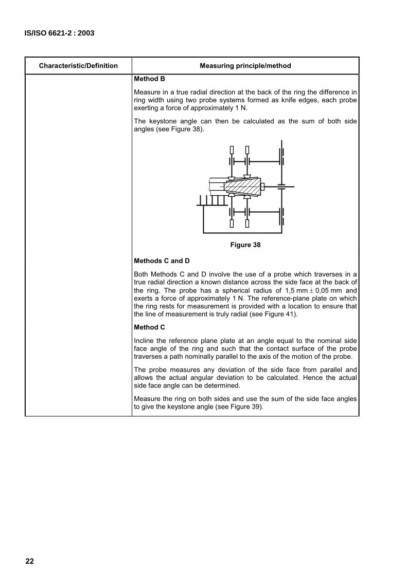
Method B
Measure in a true radial direction at the back of the ring the difference in ring width using two probe systems formed as knife edges, each probe exerting a force of approximately 1 N.
The keystone angle can then be calculated as the sum of both side angles (see Figure 38).
Figure 38
Methods C and D
Both Methods C and D involve the use of a probe which traverses in a true radial direction a known distance across the side face at the back of the ring. The probe has a spherical radius of 1,5 mm ± 0,05 mm and exerts a force of approximately 1 N. The reference-plane plate on which the ring rests for measurement is provided with a location to ensure that the line of measurement is truly radial (see Figure 41).
Method C
Incline the reference plane plate at an angle equal to the nominal side face angle of the ring and such that the contact surface of the probe traverses a path nominally parallel to the axis of the motion of the probe.
The probe measures any deviation of the side face from parallel and allows the actual angular deviation to be calculated. Hence the actual side face angle can be determined.
Measure the ring on both sides and use the sum of the side face angles to give the keystone angle (see Figure 39).
IS/ISO 6621-2 : 2003

Characteristic/Definition Measuring principle/method
Method D
Place the reference-plane plate parallel to the axis of motion of the probe and such that the ring side face lies at an angle to the reference plane equal to the nominal side face angle of the ring. The contact surface of the probe in traversing the side face describes the full movement equivalent to the side face angle: the latter can then be calculated directly.
Measure the ring on both sides and use the sum of the side face angles to give the keystone angle (see Figure 40).
a Side face horizontal. b Nominal angle of side face.
Figure 39
Figure 40
Key 1 reference-plane plate a Line of measurement.
Figure 41
IS/ISO 6621-2 : 2003
23

24
Characteristic/Definition Measuring principle/method
4.2.17 Obliqueness (in degrees)
unintentional deviation of the bisector of the keystone included angle from parallelism with the reference plane (see Figure 42)
NOTE Not applicable to rings with designed twist.
The measuring principles are identical to those for keystone angle, see 4.2.16.
When each side face angle is available, obliqueness is one half the difference between the two side face angles.
EXAMPLE 1 For a 15° included angle ring where one side is 7°40' and the other is 7°20', the obliqueness is 10'.
When the deviation from each side angle is available, the obliqueness is one half the sum of the two deviations.
EXAMPLE 2 Using Example 1, the two side face deviations are each 10' and therefore the obliqueness is 10'.
a Obliqueness.
Figure 42
4.2.18 Twist (in millimetres)
intentional torsional deviation of the section of the ring from the reference plane when the ring is restricted to nominal diameter (as in the case of asymmetrical rings such as those internally or externally stepped or bevelled) (see Figure 43)
Measure over a true radial gauge length the deviation of the ring side from a plane parallel to the reference plane, the ring being closed to nominal diameter in a bore gauge.
For non-keystone rings, measure at the back of the ring using a spherical probe of radius 1,5 mm ± 0,05 mm, exerting a force of approximately 1 N (see Figures 44 and 45).
a Top side. b Positive twist. c Negative twist.
Figure 43
IS/ISO 6621-2 : 2003

Characteristic/Definition Measuring principle/method
Dimensions in millimetres
a Top side. b Positive reading equals positive twist.
Figure 44
Dimensions in millimetres
a Top side. b Negative reading equals negative twist.
Figure 45
Twist for keystone rings is the difference in bottom side angle values measured free and confined at the back of the ring.
For the measurement of the twist, the ring shall be mounted into the gauge that the bearing running edge of the peripheral surface will be inside the gauge and not at the edge of the bore of the gauge.
NOTE Twist is measured as the linear deviation in distance from the reference plane over a gauge length of 2 mm or a minimum of 60 % of the available radial thickness.
See 4.2.16 for measuring keystone ring angles.
IS/ISO 6621-2 : 2003
25

26
Characteristic/Definition Measuring principle/method
4.2.19 Unevenness Ter, Teu
unintentional deviation of the sides of the ring from parallelism to the reference plane, i.e. twisted or dished rings (see Figures 46and 48)
NOTE Not applicable to rings with designed twist (see 4.2.18).
Measurement is as follows.
a) In the radial direction Trace radially across upper side of the ring (see Figure 47) with a probe of spherical radius 1,5 mm ± 0,05 mm exerting a force of approximately 1 N. The traces should be made centrally between the loaded points (see Figure 50). The unevenness measurement is defined in Figure 46. The largest of the four readings is taken as the measure of unevenness.
Figure 46
Figure 47
Figure 48 b) In the circumferential direction
Measure with a probe of spherical radius 1,5 mm ± 0,05 mm exerting a force of approximately 1 N on the upper side of the ring (see Figures 49 and 50), in the middle of the ring wall and centrally between the loaded points. The difference between the greatest and the least deflection is taken as the measure of the unevenness.
Load rings prior to measurement using 5 load points, one each side of the gap, one at 90°, one at 180° and one at 270°. In the case of slotted oil-control rings, load points and measurement areas shall be on the nearest available bridge and not over slot areas.
Use the following loads on each load point.
For rings < 80 mm diameter: 2,5 N.
For rings W 80 mm diameter: 5,0 N.
Figure 49
IS/ISO 6621-2 : 2003

Characteristic/Definition Measuring principle/method
Key
load points
measurement points
Figure 50
4.2.20 Helix (axial displacement of gap ends) (in millimetres)
displacement of the gap ends perpendicular to the reference plane (see Figure 51)
The gap end of the ring already in contact with the reference plane shall be loaded or clamped with a force, F, approximately 10 N. Measure the displacement of the adjacent gap end with a measuring microscope or magnifier.
The loading device or clamp shall be confined to within 15° of arc from the appropriate gap end.
Figure 51
4.2.21 Free flatness (in millimetres)
relationship between the ring in the free state and a plane parallel to its reference plane
The clean and dry ring shall drop freely of its own weight between vertical plates (see Figure 52).
The distance apart of the plates shall be equal to the maximum ring width plus the out-of-plane allowance shown below.
Table 2 — Out-of-plane-allowance Dimensions in millimetres
Ring diameter d1
Out-of-plane allowance max.
100 > d1 0,050
100 u d1 < 125 0,075
d1 W 125 0,100
NOTE For rings h1 u 1,5 mm, add 0,025 mm to the out-of-plane allowance.
IS/ISO 6621-2 : 2003
27

28
Characteristic/Definition Measuring principle/method
Figure 52
Surface plates
Size: greater than or equal to the largest free diameter of the ring.
Flatness: ± 0,0025 mm.
Roughness: Ra 0,25 µm.
Distance of plates: tolerance on spacing of plates shall be 0,010
+ mm.
4.2.22 Surface roughness Ra, Rz (in micrometres)
For the purposes of this part of ISO 6621, Rz is the preferred measurement parameter and shall be as specified in ISO 4287-1:1984, using the ten-point height measurement system.
NOTE 1 At present only surface roughness of the side faces is specified in the dimensional standards.
NOTE 2 In ISO 4287-1:1984, the Rz symbol was used to indicate the “ten-point height of irregularities”, but this was deleted from ISO 4287:1997. In some countries there are surface roughness measuring instruments in use which measure the former Rz parameter. Therefore, care must be taken when using existing technical documents and drawings because differences between results obtained with different types of instruments are not always negligibly small. Moreover, piston-ring manufacturers and their clients have up until now measured surface roughness using only the former Rz parameter. Until they have gained enough experience to enable them to switch to the new measurement, the ten-point height of irregularities will continue to be used.
See ISO 4287. Measure in accordance with ISO 4287 using any suitable profile measuring machine.
Measurement shall be based on the mean of three measured points at approximately 120° intervals.
NOTE For indications on drawings, see ISO 1302.
IS/ISO 6621-2 : 2003

Bibliography
[1] ISO 468, Surface roughness — Parameters, their values and general rules for specifying requirements
[2] ISO 1101, Geometrical Product Specifications (GPS) — Geometrical tolerancing — Tolerances of form, orientation, location and run-out
[3] ISO 1302, Geometrical Product Specifications (GPS) — Indication of surface texture in technical product documentation
[4] ISO 6622-1, Internal combustion engines — Piston rings — Part 1: Rectangular rings made of cast iron
[5] ISO 6622-2, Internal combustion engines — Piston rings — Part 2: Rectangular rings made of steel
[6] ISO 6623, Internal combustion engines — Piston rings — Scraper rings
[7] ISO 6624-1, Internal combustion engines — Piston rings — Part 1: Keystone rings made of cast iron
[8] ISO/TR 6624-2, Internal combustion engines — Piston rings — Part 2: Half keystone rings
[9] ISO 6624-3, Internal combustion engines — Piston rings — Part 3: Keystone rings made of steel
[10] ISO 6624-41), Internal combustion engines — Piston rings — Part 4: Half keystone rings made of steel
[11] ISO 6625, Internal combustion engines — Piston rings — Oil control rings
[12] ISO 6626, Internal combustion engines — Piston rings — Coil-spring-loaded oil control rings
[13] ISO 6626-2, Internal combustion engines — Piston rings — Part 2: Coil-spring-loaded oil control rings of narrow width made of cast iron
[14] ISO 6627, Internal combustion engines — Piston rings — Expander/segment oil-control rings
1) To be published.
IS/ISO 6621-2 : 2003
29

Bureau of Indian Standards
BIS is a statutory institution established under the Bureau of Indian Standards Act, 1986 to promoteharmonious development of the activities of standardization, marking and quality certification of goodsand attending to connected matters in the country.
Copyright
BIS has the copyright of all its publications. No part of these publications may be reproduced in any formwithout the prior permission in writing of BIS. This does not preclude the free use, in course of imple-menting the standard, of necessary details, such as symbols and sizes, type or grade designations.Enquiries relating to copyright be addressed to the Director (Publications), BIS.
Review of Indian Standards
Amendments are issued to standards as the need arises on the basis of comments. Standards are alsoreviewed periodically; a standard along with amendments is reaffirmed when such review indicates thatno changes are needed; if the review indicates that changes are needed, it is taken up for revision. Usersof Indian Standards should ascertain that they are in possession of the latest amendments or edition byreferring to the latest issue of ‘BIS Catalogue’ and ‘Standards: Monthly Additions’.
This Indian Standard has been developed from Doc No. : TED 2 (687).
Amendments Issued Since Publication______________________________________________________________________________________
Amendment No. Date of Issue Text Affected______________________________________________________________________________________
______________________________________________________________________________________
______________________________________________________________________________________
______________________________________________________________________________________
______________________________________________________________________________________
BUREAU OF INDIAN STANDARDSHeadquarters:
Manak Bhavan, 9 Bahadur Shah Zafar Marg, New Delhi 110002Telephones: 2323 0131, 2323 3375, 2323 9402 Website: www.bis.org.in
Regional Offices: Telephones
Central : Manak Bhavan, 9 Bahadur Shah Zafar Marg 2323 7617NEW DELHI 110002 2323 3841
Eastern : 1/14, C.I.T. Scheme VII M, V.I.P. Road, Kankurgachi 2337 8499, 2337 8561KOLKATA 700054 2337 8626, 2337 9120
Northern : SCO 335-336, Sector 34-A, CHANDIGARH 160022 260 3843260 9285
Southern : C.I.T. Campus, IV Cross Road, CHENNAI 600113 2254 1216, 2254 14422254 2519, 2254 2315
Western : Manakalaya, E9 MIDC, Marol, Andheri (East) 2832 9295, 2832 7858MUMBAI 400093 2832 7891, 2832 7892
Branches: AHMEDABAD. BANGALORE. BHOPAL. BHUBANESHWAR. COIMBATORE. DEHRADUN.FARIDABAD. GHAZIABAD. GUWAHATI. HYDERABAD. JAIPUR. KANPUR. LUCKNOW.NAGPUR. PARWANOO. PATNA. PUNE. RAJKOT. THIRUVANATHAPURAM. VISAKHAPATNAM.
Published by BIS, New Delhi
{{
{{{