Embed Size (px)
Citation preview
1
HI 98713
ISO Portable Turbidimeter
Instruction Manual
www.hannainst .com
2 3
TABLE OF CONTENTSTABLE OF CONTENTSTABLE OF CONTENTSTABLE OF CONTENTSTABLE OF CONTENTS
PREL IMINARY EXAMINATIONPRELIMINARY EXAMINATIONPRELIMINARY EXAMINATIONPRELIMINARY EXAMINATIONPRELIMINARY EXAMINATION
Please examine this product carefully. Make sure the instrument is not damaged. If any damagehas occurred during the shipment, please notify your dealer.
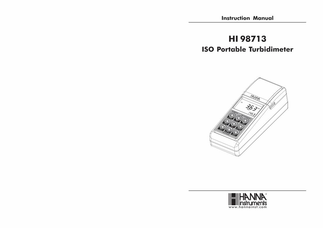
This HI 98713 Portable Turbidimeter is supplied complete with:
• Five Sample Cuvets and Caps
• Four Calibration Cuvets (HI 98713-11)
• Silicone Oil (HI 93703-58)
• Tissue for wiping the cuvets
• Five Tag holders with Tags (HI 920005)
• Batteries (4 pcs.)
• AC Adapter
• Instruction Manual
• Quick Reference Guide
• Instrument Quality Certificate
• Rigid carrying case
Note: Save all packing material until you are sure that the instrument works correctly. Anydefective item must be returned in the original packing with the supplied accessories.
HI 98713 is warranted for two years against defects in workmanship and materials when usedfor its intended purpose and maintained according to instructions. This warranty is limited torepair or replacement free of charge.Damage due to accidents, misuse, tampering or lack of prescribed maintenance is not covered.
If service is required, contact the dealer from whom you purchased the instrument. If underwarranty, report the model number, date of purchase, serial number and the nature of the failure.If the repair is not covered by the warranty, you will be notified of the charges incurred. If theinstrument is to be returned to Hanna Instruments, first obtain a Returned Goods Authorizationnumber from the Technical Service Department and then send it with shipping costs prepaid.When shipping any instrument, make sure it is properly packed for complete protection.
To validate your warranty, fill out and return the enclosed warranty card within 14 days from thedate of purchase.
WARRANTYWARRANTYWARRANTYWARRANTYWARRANTY
Dear Customer,Thank you for choosing a Hanna Instruments product. This manual will provide you with thenecessary information for correct use of the instrument.
Please read this instruction manual carefully before using the instrument.If you need additional technical information, do not hesitate to e-mail us at [email protected] see the back side of this manual for our worldwide sales and technical service contacts.
This instrument is in compliance with directives.
WARRANTY ........................................................................................................................................................... 2PRELIMINARY EXAMINATION .................................................................................................................................... 3GENERAL DESCRIPTION .......................................................................................................................................... 4TAG IDENTIFICATION SYSTEM .................................................................................................................................. 5ABBREVIATIONS .................................................................................................................................................... 5PRINCIPLE OF OPERATION ....................................................................................................................................... 6MEASUREMENT UNITS ............................................................................................................................................ 7FUNCTIONAL DESCRIPTION ...................................................................................................................................... 8SPECIFICATIONS ................................................................................................................................................... 11GENERAL TIPS FOR AN ACCURATE MEASUREMENT ................................................................................................... 12MEASUREMENT PROCEDURE ................................................................................................................................. 19CALIBRATION PROCEDURE .................................................................................................................................... 22LOGGING ............................................................................................................................................................ 26GOOD LABORATORY PRACTICE (GLP) ...................................................................................................................... 29SETUP ................................................................................................................................................................ 31LCD BACKLIGHT ................................................................................................................................................... 35TAG INSTALLATION ............................................................................................................................................... 35LED REPLACEMENT ............................................................................................................................................... 36BATTERIES MANAGEMENT .................................................................................................................................... 36PC INTERFACE ..................................................................................................................................................... 38ERROR CODES .................................................................................................................................................... 38ACCESSORIES ...................................................................................................................................................... 39RECOMMENDATIONS FOR USERS ........................................................................................................................... 39
4 5
HI 98713 is a high accuracy ISO compliant portable turbidimeter that benefits from Hanna’s yearsof experience as manufacturer of analytical instruments. The HI 98713 meets and exceeds therequirements of the ISO 7027 for water quality.
The instrument is specially designed for water quality measurements, providing a reliable andaccurate reading on low turbidity values.
The HI 98713 instrument measures the turbidity of a sample in the 0.00 to 1000 FNU (FormazinNephelometric Units) range. An effective algorithm calculates and converts the detectors output in FNU.
Depending on the measured probe and needed accuracy, normal measurement, continuousmeasurement, or signal averaging measurement can be selected.
The instrument is based on a state-of-the-art optical system, which guarantees accurate results. Theoptical system, consisting in an infrared LED and two detectors (scattered and transmitted light),assures long term stability and minimizes stray light and color interferences. It also compensates forvariations in intensity of the LED, minimizing the need of frequent calibration.
The 25 mm round cuvets made from special optical glass guarantee the repeatability and consistencyof the measurements.
Calibration can be easily performed at any time in two, three or four points (<0.1, 15, 100 and750 FNU-adjustable calibration points), using the supplied or user prepared standards.
HI 98713 has complete GLP (Good Laboratory Practice) functions that allows traceability of thecalibration conditions. The last calibration points, time and date can be checked at any time by asingle touch.
HI 98713 has a very user-friendly interface, with an easy to read, large LCD (Liquid Crystal Display).The displayed codes guide the user step by step with routine operation and through calibration.Confirmation and acoustic signals help the user during instrument operation.
The HI 98713 turbidimeter is a truly splash proof portable instrument. It is supplied with a rigidcarrying case that offers protection for harsh environments.
One battery set is enough for at least 1500 measurements. The battery charging percentage and lowbattery condition are displayed on the LCD to avoid unexpected battery failure. In order to save thebattery life, the instrument has an auto shut-off feature and will turn off after 15 minutes of non-use.
In addition, the instrument is equipped with backlight and the current time is continuously displayedon the LCD.
The instrument also provides a logging function. Up to 200 measurements can be stored in theinternal memory and consulted at any time. Data can be downloaded to a PC for storing or furtheranalysis through one of the two available ports: RS232 or USB.
For advanced field applications, the HI 98713 turbidimeter is equipped with Tag IdentificationSystem (TIS) that makes data collecting and management simpler than ever.
GENERAL DESCRIPTIONGENERAL DESCRIPTIONGENERAL DESCRIPTIONGENERAL DESCRIPTIONGENERAL DESCRIPTIONGENERAL DESCRIPTION TAG IDENTIFICATION SYSTEMTAG IDENTIFICATION SYSTEMTAG IDENTIFICATION SYSTEMTAG IDENTIFICATION SYSTEMTAG IDENTIFICATION SYSTEM
ABBREVIAT IONSABBREVIAT IONSABBREVIAT IONSABBREVIAT IONSABBREVIAT IONS
iButton®®®®® is registered Trademark of “MAXIM/DALLAS semiconductor Corp.”
Hanna is the first manufacturer of turbidity instruments that has decided to add the unique T.I.S.- Tag Identification System to our Portable Turbidimeters, to meet the more restrictive needs ofthe users and fit all advantages of this system to the turbidity measurements and data manage-ment.
The system is designed for scientific and industrial applications, or to prove during safety auditsand inspections that samples have been truly taken on pre-established locations.
The system is as easy to install as to operate. Just fix the so-called iButton® tags near yoursampling sites that need to be checked often, and with this the T.I.S. is setup. The tag containsa computer chip embedded in a durable stainless steel can. It is designed to withstand the harshenvironments, indoors or outdoors. The number of tags that can be installed is practicallyunlimited, because each tag has a unique identification code.
Immediately after tags installation you can start collecting data. Use the Portable Turbidimeter totake measurements and memorize the test result by pressing the Log-on-Demand key. Then, theinstrument will ask for the tag identification. Simply touching the iButton® with the matchingconnector on the Portable Turbidimeter does identify and authenticate logging, by storing theiButton® serial number, time and date stamp.
The power of the T.I.S. features resides in the PC application. Download all test data to your PCand use our HI 92000 Windows® compatible application software for further data management.You can sort or filter all your collected test data on different criteria like on a specific samplinglocation, parameter, date and time intervals, or fix range to filter measured values. The data canbe plotted in a graph, exported to other common Windows® applications or printed for reportingpurpose.
It is also possible to add new tags later on, thus increasing an already existing database. Eachtime the PC software recognizes a new added tag, it will ask for a description of the new samplinglocation.
FNU Formazin Nephelometric Units
LCD Liquid Crystal DisplayRTC Real Time ClockRH Relative HumidityTIS Tag Identification SystemID IdentificationISO International Standard Organization
6 7
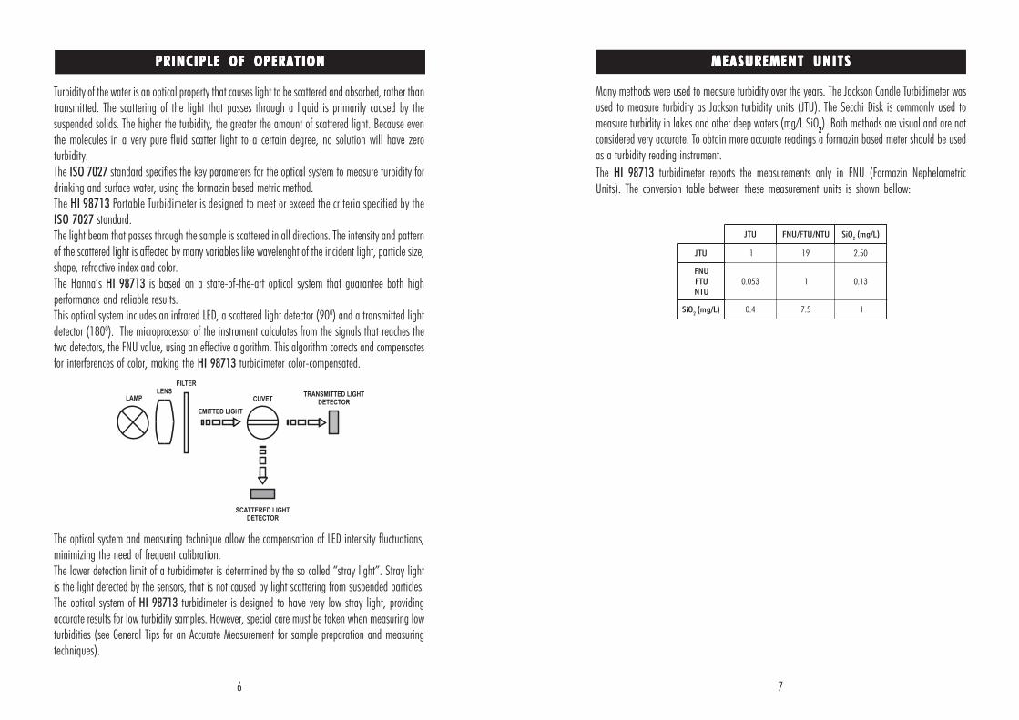
Turbidity of the water is an optical property that causes light to be scattered and absorbed, rather thantransmitted. The scattering of the light that passes through a liquid is primarily caused by thesuspended solids. The higher the turbidity, the greater the amount of scattered light. Because eventhe molecules in a very pure fluid scatter light to a certain degree, no solution will have zeroturbidity.The ISO 7027 standard specifies the key parameters for the optical system to measure turbidity fordrinking and surface water, using the formazin based metric method.The HI 98713 Portable Turbidimeter is designed to meet or exceed the criteria specified by theISO 7027 standard.The light beam that passes through the sample is scattered in all directions. The intensity and patternof the scattered light is affected by many variables like wavelenght of the incident light, particle size,shape, refractive index and color.The Hanna’s HI 98713 is based on a state-of-the-art optical system that guarantee both highperformance and reliable results.This optical system includes an infrared LED, a scattered light detector (900) and a transmitted lightdetector (1800). The microprocessor of the instrument calculates from the signals that reaches thetwo detectors, the FNU value, using an effective algorithm. This algorithm corrects and compensatesfor interferences of color, making the HI 98713 turbidimeter color-compensated.
The optical system and measuring technique allow the compensation of LED intensity fluctuations,minimizing the need of frequent calibration.The lower detection limit of a turbidimeter is determined by the so called “stray light”. Stray lightis the light detected by the sensors, that is not caused by light scattering from suspended particles.The optical system of HI 98713 turbidimeter is designed to have very low stray light, providingaccurate results for low turbidity samples. However, special care must be taken when measuring lowturbidities (see General Tips for an Accurate Measurement for sample preparation and measuringtechniques).
PRINCIPLE OF OPERATIONPRINCIPLE OF OPERATIONPRINCIPLE OF OPERATIONPRINCIPLE OF OPERATIONPRINCIPLE OF OPERATION MEASUREMENT UNITSMEASUREMENT UNITSMEASUREMENT UNITSMEASUREMENT UNITSMEASUREMENT UNITS
Many methods were used to measure turbidity over the years. The Jackson Candle Turbidimeter wasused to measure turbidity as Jackson turbidity units (JTU). The Secchi Disk is commonly used tomeasure turbidity in lakes and other deep waters (mg/L SiO
22222). Both methods are visual and are not
considered very accurate. To obtain more accurate readings a formazin based meter should be usedas a turbidity reading instrument.
The HI 98713 turbidimeter reports the measurements only in FNU (Formazin NephelometricUnits). The conversion table between these measurement units is shown bellow:
UTJ UTN/UTF/UNF OiS2
)L/gm(
UTJ 1 91 05.2
UNFUTFUTN
350.0 1 31.0
OiS2
)L/gm( 4.0 5.7 1
8 9
8) ON/OFF, press to turn the instrument ON/OFF. If no key is pressed for more than 15minutes, the instrument automatically shuts off.
9) GLP , press to enter/exit GLP feature. In SETUP it is used to increase the set values. In LogRecall it is used to select a newer record (scroll up).
10) AVG , press to set the average reading mode ON/OFF. In SETUP it is used to decrease theset values. In Log Recall it is used to select an older record (scroll down).
11) CAL, press to enter/exit calibration. During setup it is used to start/stop editing a parameter.
12) LIGHT, press to turn ON/OFF the backlight.
13) RCL, press to enter/exit viewing log content.
14) LOG/CFM, press to save the log records or to confirm the selected option.
15) READ , press to start a measurement. Press and hold READ to make a continuousmeasurement. In Log Recall it is used to see the content of a record. In GLP it is used tosee all available informations. In SETUP, during date or time editing, it is used to move thefocus on the next setting item.
16) SETUP/DEL, press to enter/exit setup. The DEL function is available in Log Recall to deleteone or all records. In GLP it is used to delete the user calibration.
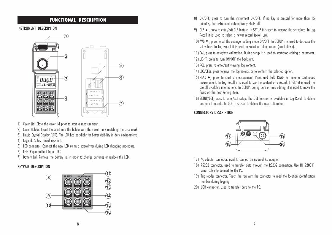
CONNECTORS DESCRIPTION
17) AC adapter connector, used to connect an external AC Adapter.
18) RS232 connector, used to transfer data through the RS232 connection. Use HI 920011serial cable to connect to the PC.
19) Tag reader connector. Touch the tag with the connector to read the location identificationnumber during logging.
20) USB connector, used to transfer data to the PC.
FUNCTIONAL DESCRIPTIONFUNCTIONAL DESCRIPTIONFUNCTIONAL DESCRIPTIONFUNCTIONAL DESCRIPTIONFUNCTIONAL DESCRIPTION
INSTRUMENT DESCRIPTION
1) Cuvet Lid. Close the cuvet lid prior to start a measurement.
2) Cuvet Holder. Insert the cuvet into the holder with the cuvet mark matching the case mark.
3) Liquid Crystal Display (LCD). The LCD has backlight for better visibility in dark environments.
4) Keypad. Splash proof resistant.
5) LED connector. Connect the new LED using a screwdriver during LED changing procedure.
6) LED. Replaceable infrared LED.
7) Battery Lid. Remove the battery lid in order to change batteries or replace the LED.
KEYPAD DESCRIPTION
10 11
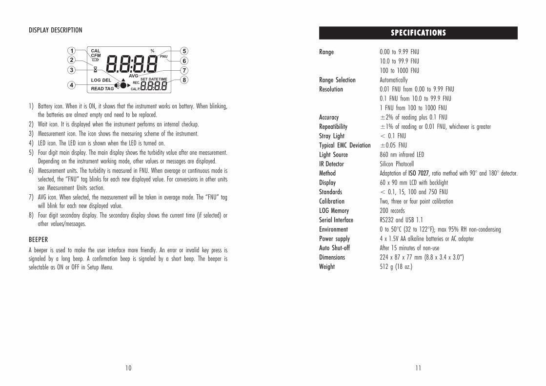
DISPLAY DESCRIPTION
1) Battery icon. When it is ON, it shows that the instrument works on battery. When blinking,the batteries are almost empty and need to be replaced.
2) Wait icon. It is displayed when the instrument performs an internal checkup.
3) Measurement icon. The icon shows the measuring scheme of the instrument.
4) LED icon. The LED icon is shown when the LED is turned on.
5) Four digit main display. The main display shows the turbidity value after one measurement.Depending on the instrument working mode, other values or messages are displayed.
6) Measurement units. The turbidity is measured in FNU. When average or continuous mode isselected, the “FNU” tag blinks for each new displayed value. For conversions in other unitssee Measurement Units section.
7) AVG icon. When selected, the measurement will be taken in average mode. The “FNU” tagwill blink for each new displayed value.
8) Four digit secondary display. The secondary display shows the current time (if selected) orother values/messages.
BEEPER
A beeper is used to make the user interface more friendly. An error or invalid key press issignaled by a long beep. A confirmation beep is signaled by a short beep. The beeper isselectable as ON or OFF in Setup Menu.
Range 0.00 to 9.99 FNU
10.0 to 99.9 FNU
100 to 1000 FNU
Range Selection Automatically
Resolution 0.01 FNU from 0.00 to 9.99 FNU
0.1 FNU from 10.0 to 99.9 FNU
1 FNU from 100 to 1000 FNU
Accuracy ±2% of reading plus 0.1 FNU
Repeatibility ±1% of reading or 0.01 FNU, whichever is greater
Stray Light < 0.1 FNU
Typical EMC Deviation ±0.05 FNU
Light Source 860 nm infrared LED
IR Detector Silicon Photocell
Method Adaptation of ISO 7027, ratio method with 90° and 180° detector.
Display 60 x 90 mm LCD with backlight
Standards < 0.1, 15, 100 and 750 FNU
Calibration Two, three or four point calibration
LOG Memory 200 records
Serial Interface RS232 and USB 1.1
Environment 0 to 50°C (32 to 122°F); max 95% RH non-condensing
Power supply 4 x 1.5V AA alkaline batteries or AC adapter
Auto Shut-off After 15 minutes of non-use
Dimensions 224 x 87 x 77 mm (8.8 x 3.4 x 3.0”)
Weight 512 g (18 oz.)
SPECIF ICATIONSSPECIF ICATIONSSPECIF ICATIONSSPECIF ICATIONSSPECIF ICATIONS
12 13
GENERAL TIPS FOR AN ACCURATE MEASUREMENTGENERAL TIPS FOR AN ACCURATE MEASUREMENTGENERAL TIPS FOR AN ACCURATE MEASUREMENTGENERAL TIPS FOR AN ACCURATE MEASUREMENTGENERAL TIPS FOR AN ACCURATE MEASUREMENT
CUVET
The cuvet is part of the optical system in all measurements. The light reaches the sample bypassing through the cuvet glass. As a result, the measurement can be affected by the glassimperfections, dirt, dust, scratches, or fingerprints present on the cuvet surface.
CUVET HANDLING
The cuvets should be free of scratches or cracks. Any cuvet with visible scratches will bediscarded. The cuvets should be periodically washed with acid. After washing, the cuvets shouldbe well rinsed many times with distilled or deionized water. Allow cuvets to air-dry and storethem for long periods of time with caps, to avoid dirt entering inside. Always handle the cuvetby touching only the cap or its top side (over the horizontal line).
Always store the cuvets in separate boxes or with separators between them to avoid scratches onthe surface.
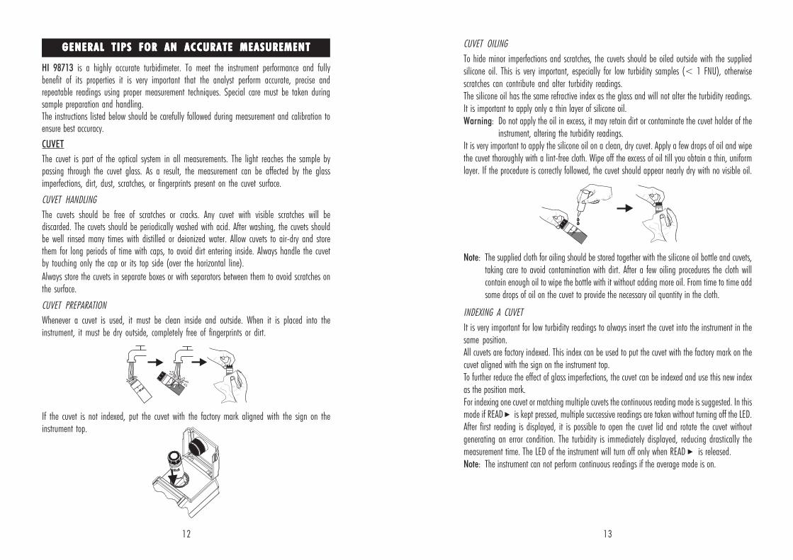
CUVET PREPARATION
Whenever a cuvet is used, it must be clean inside and outside. When it is placed into theinstrument, it must be dry outside, completely free of fingerprints or dirt.
If the cuvet is not indexed, put the cuvet with the factory mark aligned with the sign on theinstrument top.
HI 98713 is a highly accurate turbidimeter. To meet the instrument performance and fullybenefit of its properties it is very important that the analyst perform accurate, precise andrepeatable readings using proper measurement techniques. Special care must be taken duringsample preparation and handling.The instructions listed below should be carefully followed during measurement and calibration toensure best accuracy.
CUVET OILING
To hide minor imperfections and scratches, the cuvets should be oiled outside with the suppliedsilicone oil. This is very important, especially for low turbidity samples (< 1 FNU), otherwisescratches can contribute and alter turbidity readings.The silicone oil has the same refractive index as the glass and will not alter the turbidity readings.It is important to apply only a thin layer of silicone oil.Warning: Do not apply the oil in excess, it may retain dirt or contaminate the cuvet holder of the
instrument, altering the turbidity readings.It is very important to apply the silicone oil on a clean, dry cuvet. Apply a few drops of oil and wipethe cuvet thoroughly with a lint-free cloth. Wipe off the excess of oil till you obtain a thin, uniformlayer. If the procedure is correctly followed, the cuvet should appear nearly dry with no visible oil.
Note: The supplied cloth for oiling should be stored together with the silicone oil bottle and cuvets,taking care to avoid contamination with dirt. After a few oiling procedures the cloth willcontain enough oil to wipe the bottle with it without adding more oil. From time to time addsome drops of oil on the cuvet to provide the necessary oil quantity in the cloth.
INDEXING A CUVET
It is very important for low turbidity readings to always insert the cuvet into the instrument in thesame position.All cuvets are factory indexed. This index can be used to put the cuvet with the factory mark on thecuvet aligned with the sign on the instrument top.To further reduce the effect of glass imperfections, the cuvet can be indexed and use this new indexas the position mark.For indexing one cuvet or matching multiple cuvets the continuous reading mode is suggested. In thismode if READ is kept pressed, multiple successive readings are taken without turning off the LED.After first reading is displayed, it is possible to open the cuvet lid and rotate the cuvet withoutgenerating an error condition. The turbidity is immediately displayed, reducing drastically themeasurement time. The LED of the instrument will turn off only when READ is released.Note: The instrument can not perform continuous readings if the average mode is on.
14
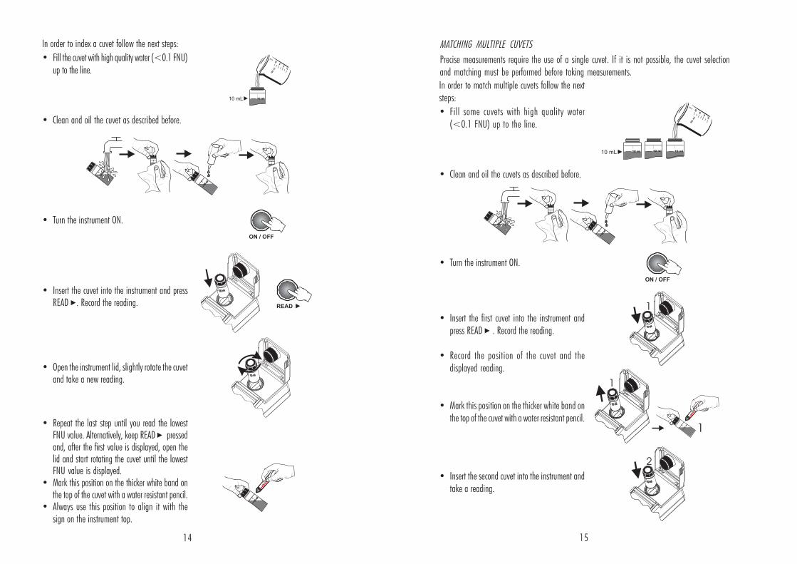
In order to index a cuvet follow the next steps:
• Fill the cuvet with high quality water (<0.1 FNU)up to the line.
• Clean and oil the cuvet as described before.
• Turn the instrument ON.
• Insert the cuvet into the instrument and pressREAD . Record the reading.
• Open the instrument lid, slightly rotate the cuvetand take a new reading.
• Repeat the last step until you read the lowestFNU value. Alternatively, keep READ pressedand, after the first value is displayed, open thelid and start rotating the cuvet until the lowestFNU value is displayed.
• Mark this position on the thicker white band onthe top of the cuvet with a water resistant pencil.
• Always use this position to align it with thesign on the instrument top.
In order to match multiple cuvets follow the nextsteps:
• Fill some cuvets with high quality water(<0.1 FNU) up to the line.
• Clean and oil the cuvets as described before.
• Turn the instrument ON.
• Insert the first cuvet into the instrument andpress READ . Record the reading.
• Record the position of the cuvet and thedisplayed reading.
• Mark this position on the thicker white band onthe top of the cuvet with a water resistant pencil.
• Insert the second cuvet into the instrument andtake a reading.
MATCHING MULTIPLE CUVETS
Precise measurements require the use of a single cuvet. If it is not possible, the cuvet selectionand matching must be performed before taking measurements.
15
16 17
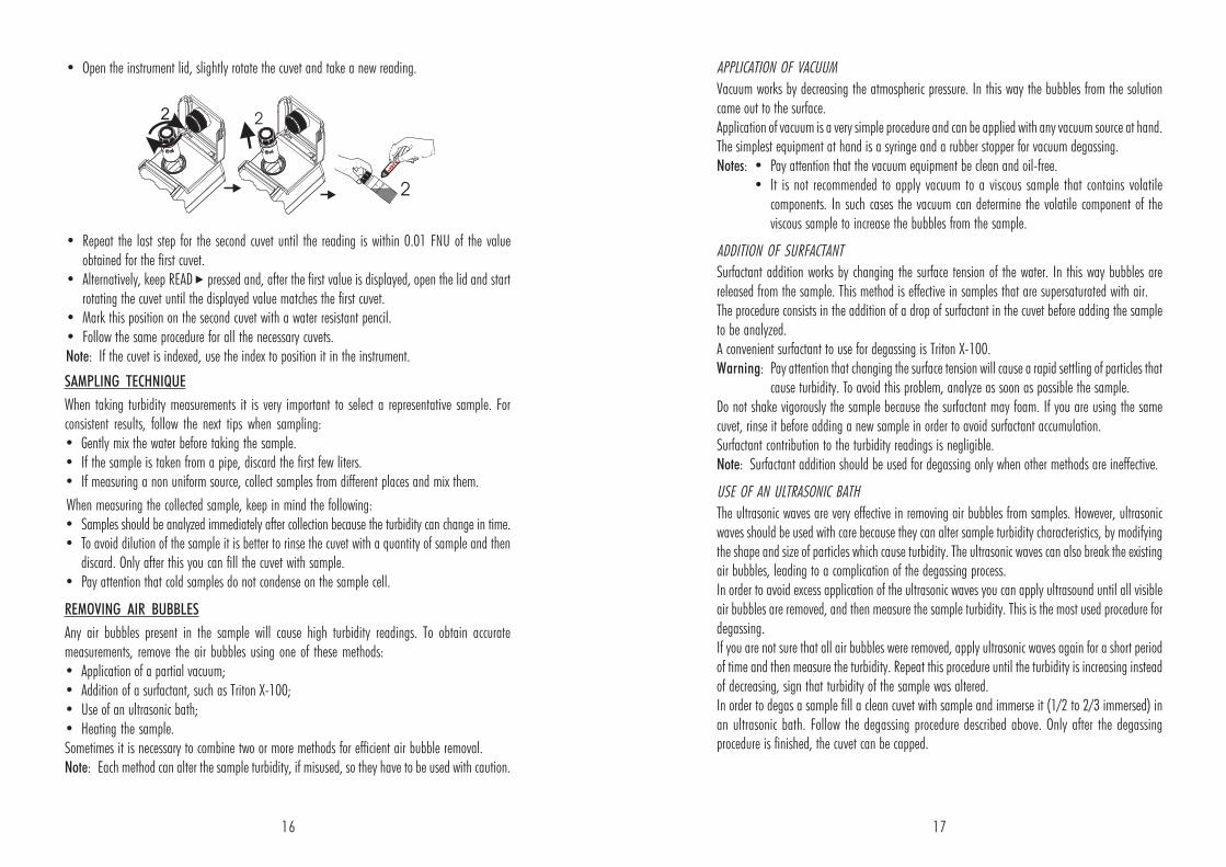
• Open the instrument lid, slightly rotate the cuvet and take a new reading.
• Repeat the last step for the second cuvet until the reading is within 0.01 FNU of the valueobtained for the first cuvet.
• Alternatively, keep READ pressed and, after the first value is displayed, open the lid and startrotating the cuvet until the displayed value matches the first cuvet.
• Mark this position on the second cuvet with a water resistant pencil.• Follow the same procedure for all the necessary cuvets.Note: If the cuvet is indexed, use the index to position it in the instrument.
APPLICATION OF VACUUM
Vacuum works by decreasing the atmospheric pressure. In this way the bubbles from the solutioncame out to the surface.Application of vacuum is a very simple procedure and can be applied with any vacuum source at hand.The simplest equipment at hand is a syringe and a rubber stopper for vacuum degassing.Notes: • Pay attention that the vacuum equipment be clean and oil-free.
• It is not recommended to apply vacuum to a viscous sample that contains volatilecomponents. In such cases the vacuum can determine the volatile component of theviscous sample to increase the bubbles from the sample.
ADDITION OF SURFACTANT
Surfactant addition works by changing the surface tension of the water. In this way bubbles arereleased from the sample. This method is effective in samples that are supersaturated with air.The procedure consists in the addition of a drop of surfactant in the cuvet before adding the sampleto be analyzed.A convenient surfactant to use for degassing is Triton X-100.Warning: Pay attention that changing the surface tension will cause a rapid settling of particles that
cause turbidity. To avoid this problem, analyze as soon as possible the sample.Do not shake vigorously the sample because the surfactant may foam. If you are using the samecuvet, rinse it before adding a new sample in order to avoid surfactant accumulation.Surfactant contribution to the turbidity readings is negligible.Note: Surfactant addition should be used for degassing only when other methods are ineffective.
USE OF AN ULTRASONIC BATH
The ultrasonic waves are very effective in removing air bubbles from samples. However, ultrasonicwaves should be used with care because they can alter sample turbidity characteristics, by modifyingthe shape and size of particles which cause turbidity. The ultrasonic waves can also break the existingair bubbles, leading to a complication of the degassing process.In order to avoid excess application of the ultrasonic waves you can apply ultrasound until all visibleair bubbles are removed, and then measure the sample turbidity. This is the most used procedure fordegassing.If you are not sure that all air bubbles were removed, apply ultrasonic waves again for a short periodof time and then measure the turbidity. Repeat this procedure until the turbidity is increasing insteadof decreasing, sign that turbidity of the sample was altered.In order to degas a sample fill a clean cuvet with sample and immerse it (1/2 to 2/3 immersed) inan ultrasonic bath. Follow the degassing procedure described above. Only after the degassingprocedure is finished, the cuvet can be capped.
SAMPLING TECHNIQUE
When taking turbidity measurements it is very important to select a representative sample. Forconsistent results, follow the next tips when sampling:• Gently mix the water before taking the sample.• If the sample is taken from a pipe, discard the first few liters.• If measuring a non uniform source, collect samples from different places and mix them.
When measuring the collected sample, keep in mind the following:• Samples should be analyzed immediately after collection because the turbidity can change in time.• To avoid dilution of the sample it is better to rinse the cuvet with a quantity of sample and then
discard. Only after this you can fill the cuvet with sample.• Pay attention that cold samples do not condense on the sample cell.
REMOVING AIR BUBBLES
Any air bubbles present in the sample will cause high turbidity readings. To obtain accuratemeasurements, remove the air bubbles using one of these methods:• Application of a partial vacuum;• Addition of a surfactant, such as Triton X-100;• Use of an ultrasonic bath;• Heating the sample.Sometimes it is necessary to combine two or more methods for efficient air bubble removal.Note: Each method can alter the sample turbidity, if misused, so they have to be used with caution.
18 19
MEASUREMENT PROCEDUREMEASUREMENT PROCEDUREMEASUREMENT PROCEDUREMEASUREMENT PROCEDUREMEASUREMENT PROCEDURE
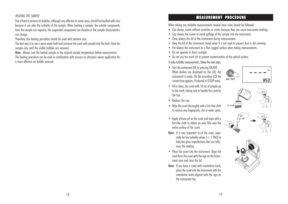
To take turbidity measurements, follow the next steps:
• Turn the instrument ON by pressing ON/OFF.When dashes are displayed on the LCD, theinstrument is ready. On the secondary LCD thecurrent time appears, if selected in SETUP menu.
• Fill a clean, dry cuvet with 10 mL of sample upto the mark, taking care to handle the cuvet bythe top.
• Replace the cap.
• Wipe the cuvet thoroughly with a lint-free clothto remove any fingerprints, dirt or water spots.
• Apply silicone oil on the cuvet and wipe with alint-free cloth to obtain an even film over theentire surface of the cuvet.
Note: It is very important to oil the cuvet, espe-cially for low turbidity values (< 1 FNU) tohide the glass imperfections that can influ-ence the reading.
• Place the cuvet into the instrument. Align themark from the cuvet with the sign on the instru-ment case and close the lid.
Note: If you have a cuvet with orientation mark,place the cuvet into the instrument with theorientation mark aligned with the sign onthe instrument top.
HEATING THE SAMPLE
Use of heat to remove air bubbles, although very effective in some cases, should be handled with carebecause it can alter the turbidity of the sample. When heating a sample, the volatile componentsfrom the sample can vaporize, the suspended components can dissolve or the sample characteristicscan change.Therefore, the heating procedure should be used with extreme care.The best way is to use a warm water bath and immerse the cuvet with sample into the bath. Heat thesample only until the visible bubbles are removed.Note: Always cool the heated sample to the original sample temperature before measurement.The heating procedure can be used in combination with vacuum or ultrasonic waves application fora more effective air bubble removal.
When taking any turbidity measurements several basic rules should be followed:
• Use always cuvets without scratches or cracks because they can cause inaccurate readings.• Cap always the cuvets to avoid spillage of the sample into the instrument.• Close always the lid of the instrument during measurement.• Keep the lid of the instrument closed when it is not used to prevent dust or dirt entering.• Put always the instrument on a flat, rugged surface when taking measurements.• Do not operate in direct sunlight.• Do not use too much oil to prevent contamination of the optical system.
20 21
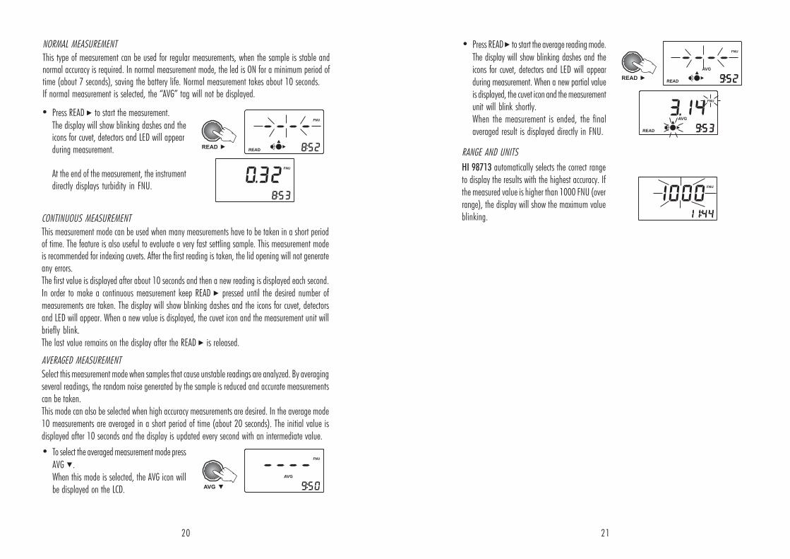
• Press READ to start the measurement.
The display will show blinking dashes and theicons for cuvet, detectors and LED will appearduring measurement.
At the end of the measurement, the instrumentdirectly displays turbidity in FNU.
NORMAL MEASUREMENT
This type of measurement can be used for regular measurements, when the sample is stable andnormal accuracy is required. In normal measurement mode, the led is ON for a minimum period oftime (about 7 seconds), saving the battery life. Normal measurement takes about 10 seconds.If normal measurement is selected, the “AVG” tag will not be displayed.
CONTINUOUS MEASUREMENT
This measurement mode can be used when many measurements have to be taken in a short periodof time. The feature is also useful to evaluate a very fast settling sample. This measurement modeis recommended for indexing cuvets. After the first reading is taken, the lid opening will not generateany errors.The first value is displayed after about 10 seconds and then a new reading is displayed each second.In order to make a continuous measurement keep READ pressed until the desired number ofmeasurements are taken. The display will show blinking dashes and the icons for cuvet, detectorsand LED will appear. When a new value is displayed, the cuvet icon and the measurement unit willbriefly blink.The last value remains on the display after the READ is released.
AVERAGED MEASUREMENT
Select this measurement mode when samples that cause unstable readings are analyzed. By averagingseveral readings, the random noise generated by the sample is reduced and accurate measurementscan be taken.This mode can also be selected when high accuracy measurements are desired. In the average mode10 measurements are averaged in a short period of time (about 20 seconds). The initial value isdisplayed after 10 seconds and the display is updated every second with an intermediate value.
• To select the averaged measurement mode press
AVG .When this mode is selected, the AVG icon willbe displayed on the LCD.
• Press READ to start the average reading mode.
The display will show blinking dashes and theicons for cuvet, detectors and LED will appearduring measurement. When a new partial valueis displayed, the cuvet icon and the measurementunit will blink shortly.When the measurement is ended, the finalaveraged result is displayed directly in FNU.
RANGE AND UNITS
HI 98713 automatically selects the correct rangeto display the results with the highest accuracy. Ifthe measured value is higher than 1000 FNU (overrange), the display will show the maximum valueblinking.
22 23
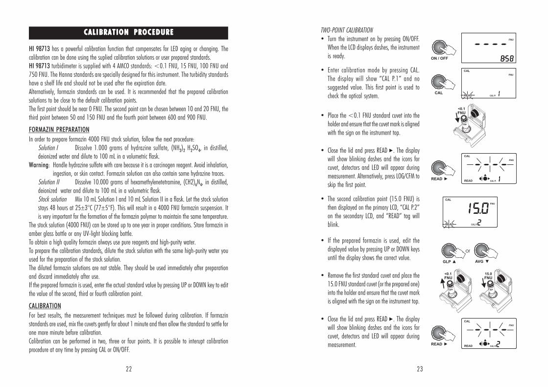
TWO-POINT CALIBRATION• Turn the instrument on by pressing ON/OFF.
When the LCD displays dashes, the instrumentis ready.
• Enter calibration mode by pressing CAL.The display will show “CAL P.1” and nosuggested value. This first point is used tocheck the optical system.
• Place the <0.1 FNU standard cuvet into theholder and ensure that the cuvet mark is alignedwith the sign on the instrument top.
• Close the lid and press READ . The displaywill show blinking dashes and the icons forcuvet, detectors and LED will appear duringmeasurement. Alternatively, press LOG/CFM toskip the first point.
• The second calibration point (15.0 FNU) isthen displayed on the primary LCD, “CAL P.2”on the secondary LCD, and “READ” tag willblink.
• If the prepared formazin is used, edit thedisplayed value by pressing UP or DOWN keysuntil the display shows the correct value.
• Remove the first standard cuvet and place the15.0 FNU standard cuvet (or the prepared one)into the holder and ensure that the cuvet markis aligned with the sign on the instrument top.
• Close the lid and press READ . The displaywill show blinking dashes and the icons forcuvet, detectors and LED will appear duringmeasurement.
CALIBRATION PROCEDURECALIBRATION PROCEDURECALIBRATION PROCEDURECALIBRATION PROCEDURECALIBRATION PROCEDURE
HI 98713 has a powerful calibration function that compensates for LED aging or changing. Thecalibration can be done using the suplied calibration solutions or user prepared standards.HI 98713 turbidimeter is supplied with 4 AMCO standards: <0.1 FNU, 15 FNU, 100 FNU and750 FNU. The Hanna standards are specially designed for this instrument. The turbidity standardshave a shelf life and should not be used after the expiration date.Alternatively, formazin standards can be used. It is recommended that the prepared calibrationsolutions to be close to the default calibration points.The first point should be near 0 FNU. The second point can be chosen between 10 and 20 FNU, thethird point between 50 and 150 FNU and the fourth point between 600 and 900 FNU.
FORMAZIN PREPARATION
In order to prepare formazin 4000 FNU stock solution, follow the next procedure:Solution I Dissolve 1.000 grams of hydrazine sulfate, (NH2)2 H2SO4, in distilled,deionized water and dilute to 100 mL in a volumetric flask.
Warning: Handle hydrazine sulfate with care because it is a carcinogen reagent. Avoid inhalation,ingestion, or skin contact. Formazin solution can also contain some hydrazine traces.
Solution II Dissolve 10.000 grams of hexamethylenetetramine, (CH2)6N4, in distilled,deionized water and dilute to 100 mL in a volumetric flask.Stock solution Mix 10 mL Solution I and 10 mL Solution II in a flask. Let the stock solutionstays 48 hours at 25±3°C (77±5°F). This will result in a 4000 FNU formazin suspension. Itis very important for the formation of the formazin polymer to maintain the same temperature.
The stock solution (4000 FNU) can be stored up to one year in proper conditions. Store formazin inamber glass bottle or any UV-light blocking bottle.To obtain a high quality formazin always use pure reagents and high-purity water.To prepare the calibration standards, dilute the stock solution with the same high-purity water youused for the preparation of the stock solution.The diluted formazin solutions are not stable. They should be used immediately after preparationand discard immediately after use.If the prepared formazin is used, enter the actual standard value by pressing UP or DOWN key to editthe value of the second, third or fourth calibration point.
CALIBRATION
For best results, the measurement techniques must be followed during calibration. If formazinstandards are used, mix the cuvets gently for about 1 minute and then allow the standard to settle forone more minute before calibration.Calibration can be performed in two, three or four points. It is possible to interupt calibrationprocedure at any time by pressing CAL or ON/OFF.
24 25
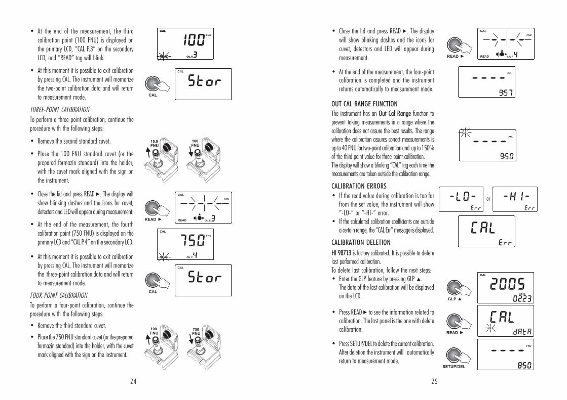
• At the end of the measurement, the thirdcalibration point (100 FNU) is displayed onthe primary LCD, “CAL P.3” on the secondaryLCD, and “READ” tag will blink.
• At this moment it is possible to exit calibrationby pressing CAL. The instrument will memorizethe two-point calibration data and will returnto measurement mode.
THREE-POINT CALIBRATION
To perform a three-point calibration, continue theprocedure with the following steps:
• Remove the second standard cuvet.
• Place the 100 FNU standard cuvet (or theprepared formazin standard) into the holder,with the cuvet mark aligned with the sign onthe instrument.
• Close the lid and press READ . The display willshow blinking dashes and the icons for cuvet,detectors and LED will appear during measurement.
• At the end of the measurement, the fourthcalibration point (750 FNU) is displayed on theprimary LCD and “CAL P.4” on the secondary LCD.
• At this moment it is possible to exit calibrationby pressing CAL. The instrument will memorizethe three-point calibration data and will returnto measurement mode.
FOUR-POINT CALIBRATION
To perform a four-point calibration, continue theprocedure with the following steps:
• Remove the third standard cuvet.
• Place the 750 FNU standard cuvet (or the preparedformazin standard) into the holder, with the cuvetmark aligned with the sign on the instrument.
OUT CAL RANGE FUNCTION
The instrument has an Out Cal Range function toprevent taking measurements in a range where thecalibration does not assure the best results. The rangewhere the calibration assures correct measurements isup to 40 FNU for two-point calibration and up to 150%of the third point value for three-point calibration.The display will show a blinking “CAL” tag each time themeasurements are taken outside the calibration range.
CALIBRATION ERRORS
• If the read value during calibration is too farfrom the set value, the instrument will show“-LO-” or “-HI-” error.
• If the calculated calibration coefficients are outsidea certain range, the “CAL Err” message is displayed.
CALIBRATION DELETION
HI 98713 is factory calibrated. It is possible to deletelast performed calibration.To delete last calibration, follow the next steps:• Enter the GLP feature by pressing GLP .
The date of the last calibration will be displayedon the LCD.
• Press READ to see the information related tocalibration. The last panel is the one with deletecalibration.
• Press SETUP/DEL to delete the current calibration.After deletion the instrument will automaticallyreturn to measurement mode.
• Close the lid and press READ . The displaywill show blinking dashes and the icons forcuvet, detectors and LED will appear duringmeasurement.
• At the end of the measurement, the four-pointcalibration is completed and the instrumentreturns automatically to measurement mode.
or
26 27
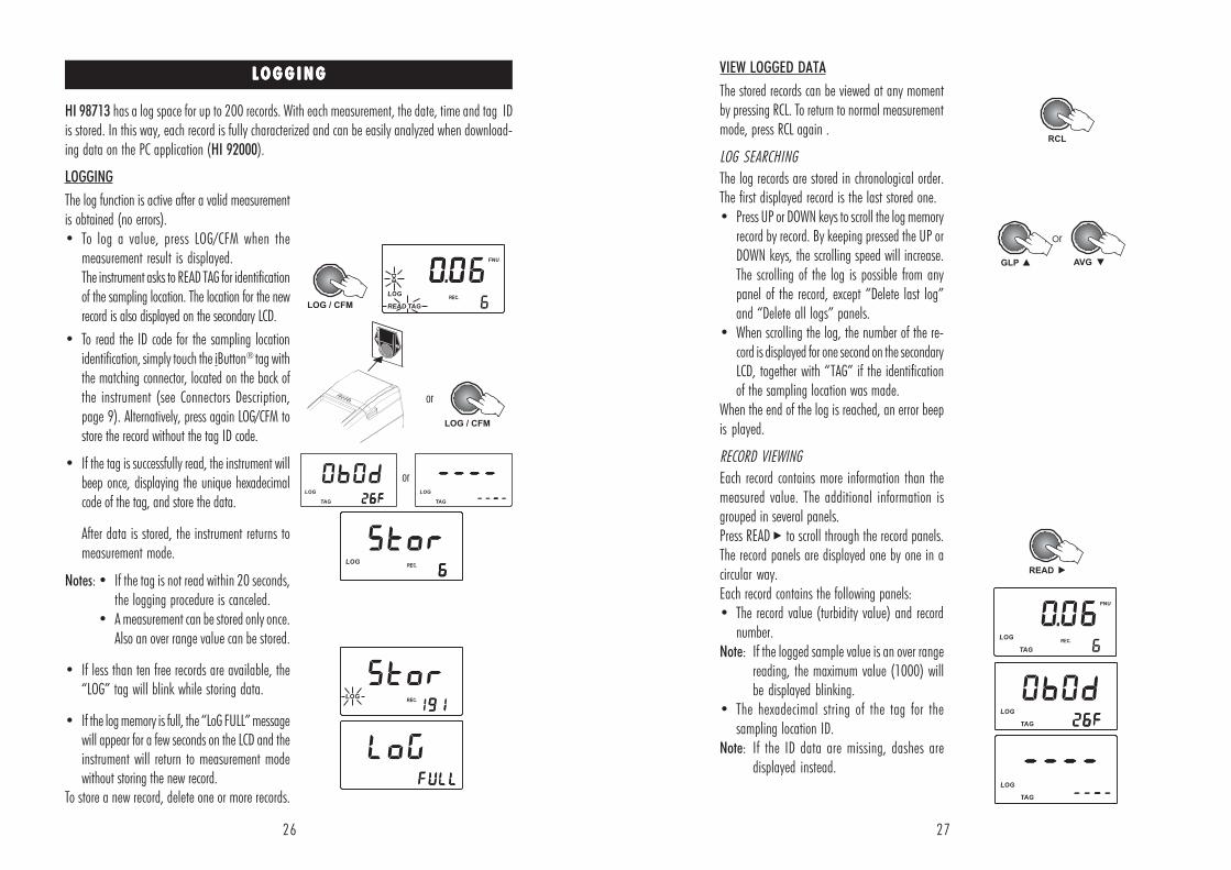
VIEW LOGGED DATA
The stored records can be viewed at any momentby pressing RCL. To return to normal measurementmode, press RCL again .
LOG SEARCHING
The log records are stored in chronological order.The first displayed record is the last stored one.• Press UP or DOWN keys to scroll the log memory
record by record. By keeping pressed the UP orDOWN keys, the scrolling speed will increase.The scrolling of the log is possible from anypanel of the record, except “Delete last log”and “Delete all logs” panels.
• When scrolling the log, the number of the re-cord is displayed for one second on the secondaryLCD, together with “TAG” if the identificationof the sampling location was made.
When the end of the log is reached, an error beepis played.
RECORD VIEWING
Each record contains more information than themeasured value. The additional information isgrouped in several panels.Press READ to scroll through the record panels.The record panels are displayed one by one in acircular way.Each record contains the following panels:• The record value (turbidity value) and record
number.Note: If the logged sample value is an over range
reading, the maximum value (1000) willbe displayed blinking.
• The hexadecimal string of the tag for thesampling location ID.
Note: If the ID data are missing, dashes aredisplayed instead.
L O G G I N GL O G G I N GL O G G I N GL O G G I N GL O G G I N G
LOGGING
The log function is active after a valid measurementis obtained (no errors).• To log a value, press LOG/CFM when the
measurement result is displayed.The instrument asks to READ TAG for identificationof the sampling location. The location for the newrecord is also displayed on the secondary LCD.
• To read the ID code for the sampling locationidentification, simply touch the iButton®
tag withthe matching connector, located on the back ofthe instrument (see Connectors Description,page 9). Alternatively, press again LOG/CFM tostore the record without the tag ID code.
• If the tag is successfully read, the instrument willbeep once, displaying the unique hexadecimalcode of the tag, and store the data.
After data is stored, the instrument returns tomeasurement mode.
Notes: • If the tag is not read within 20 seconds,the logging procedure is canceled.
• A measurement can be stored only once.Also an over range value can be stored.
• If less than ten free records are available, the“LOG” tag will blink while storing data.
• If the log memory is full, the “LoG FULL” messagewill appear for a few seconds on the LCD and theinstrument will return to measurement modewithout storing the new record.
To store a new record, delete one or more records.
HI 98713 has a log space for up to 200 records. With each measurement, the date, time and tag IDis stored. In this way, each record is fully characterized and can be easily analyzed when download-ing data on the PC application (HI 92000).
or
or
28 29
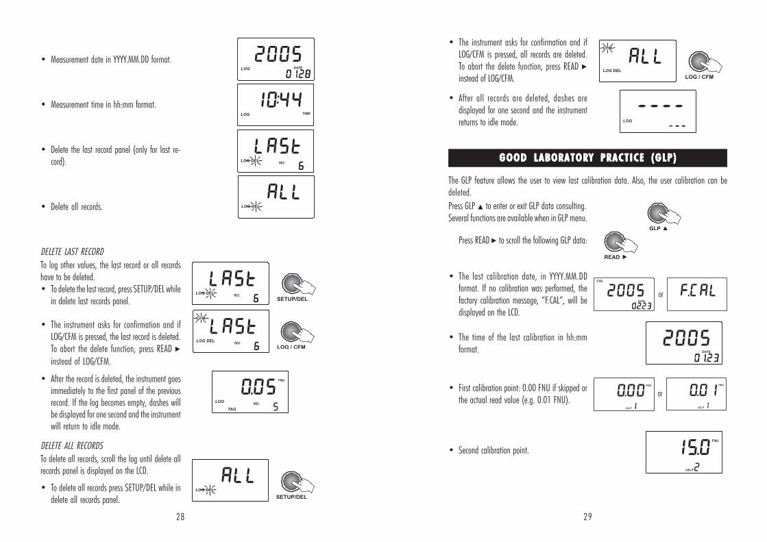
Press GLP to enter or exit GLP data consulting.Several functions are available when in GLP menu.
Press READ to scroll the following GLP data:
• The last calibration date, in YYYY.MM.DDformat. If no calibration was performed, thefactory calibration message, “F.CAL”, will bedisplayed on the LCD.
• The time of the last calibration in hh:mmformat.
• First calibration point: 0.00 FNU if skipped orthe actual read value (e.g. 0.01 FNU).
• Second calibration point.
GOOD LABORATORY PRACTICE (GLP)GOOD LABORATORY PRACTICE (GLP)GOOD LABORATORY PRACTICE (GLP)GOOD LABORATORY PRACTICE (GLP)GOOD LABORATORY PRACTICE (GLP)
• Measurement date in YYYY.MM.DD format.
• Measurement time in hh:mm format.
• Delete the last record panel (only for last re-cord).
• Delete all records.
DELETE LAST RECORD
To log other values, the last record or all recordshave to be deleted.• To delete the last record, press SETUP/DEL while
in delete last records panel.
• The instrument asks for confirmation and ifLOG/CFM is pressed, the last record is deleted.To abort the delete function, press READ
instead of LOG/CFM.
• After the record is deleted, the instrument goesimmediately to the first panel of the previousrecord. If the log becomes empty, dashes willbe displayed for one second and the instrumentwill return to idle mode.
DELETE ALL RECORDS
To delete all records, scroll the log until delete allrecords panel is displayed on the LCD.
• To delete all records press SETUP/DEL while indelete all records panel.
• The instrument asks for confirmation and ifLOG/CFM is pressed, all records are deleted.To abort the delete function, press READ instead of LOG/CFM.
• After all records are deleted, dashes aredisplayed for one second and the instrumentreturns to idle mode.
The GLP feature allows the user to view last calibration data. Also, the user calibration can bedeleted.
or
or
30 31
S E T U PS E T U PS E T U PS E T U PS E T U P
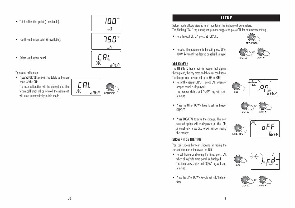
• To enter/exit SETUP, press SETUP/DEL.
• To select the parameter to be edit, press UP orDOWN keys until the desired panel is displayed.
SET BEEPERThe HI 98713 has a built-in beeper that signalsthe tag read, the key press and the error conditions.The beeper can be selected to be ON or OFF.• To set the beeper ON/OFF, press CAL when set
beeper panel is displayed.The beeper status and “CFM” tag will startblinking.
• Press the UP or DOWN keys to set the beeperON/OFF.
• Press LOG/CFM to save the change. The newselected option will be displayed on the LCD.Alternatively, press CAL to exit without savingthe changes.
SHOW / HIDE THE TIME
You can choose between showing or hiding thecurrent hour and minutes on the LCD.• To set hiding or showing the time, press CAL
when show/hide time panel is displayed.The time show status and “CFM” tag will startblinking.
• Press the UP or DOWN keys to set lcd / hide fortime.
• Third calibration point (if available).
• Fourth calibration point (if available).
• Delete calibration panel.
To delete calibration:• Press SETUP/DEL while in the delete calibration
panel of the GLP.The user calibration will be deleted and thefactory calibration will be restored. The instrumentwill enter automatically in idle mode.
Setup mode allows viewing and modifying the instrument parameters.The blinking “CAL” tag during setup mode suggest to press CAL for parameters editing.
32 33
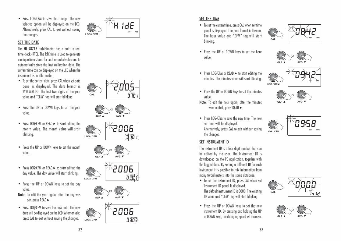
• Press LOG/CFM to save the change. The newselected option will be displayed on the LCD.Alternatively, press CAL to exit without savingthe changes.
SET THE DATE
The HI 98713 turbidimeter has a built-in realtime clock (RTC). The RTC time is used to generatea unique time stamp for each recorded value and toautomatically store the last calibration date. Thecurrent time can be displayed on the LCD when theinstrument is in idle mode.• To set the current date, press CAL when set date
panel is displayed. The date format isYYYY.MM.DD. The last two digits of the yearvalue and “CFM” tag will start blinking.
• Press the UP or DOWN keys to set the yearvalue.
• Press LOG/CFM or READ to start editing themonth value. The month value will startblinking.
• Press the UP or DOWN keys to set the monthvalue.
• Press LOG/CFM or READ to start editing theday value. The day value will start blinking.
• Press the UP or DOWN keys to set the dayvalue.
Note: To edit the year again, after the day wasset, press READ .
• Press LOG/CFM to save the new date. The newdate will be displayed on the LCD. Alternatively,press CAL to exit without saving the changes.
SET THE TIME
• To set the current time, press CAL when set timepanel is displayed. The time format is hh:mm.The hour value and “CFM” tag will startblinking.
• Press the UP or DOWN keys to set the hourvalue.
• Press LOG/CFM or READ to start editing theminutes. The minutes value will start blinking.
• Press the UP or DOWN keys to set the minutesvalue.
Note: To edit the hour again, after the minuteswere edited, press READ .
• Press LOG/CFM to save the new time. The newset time will be displayed.Alternatively, press CAL to exit without savingthe changes.
SET INSTRUMENT ID
The instrument ID is a four digit number that canbe edited by the user. The instrument ID isdownloaded on the PC application, together withthe logged data. By setting a different ID for eachinstrument it is possible to mix information frommany turbidimeters into the same database.• To set the instrument ID, press CAL when set
instrument ID panel is displayed.The default instrument ID is 0000. The existingID value and “CFM” tag will start blinking.
• Press the UP or DOWN keys to set the newinstrument ID. By pressing and holding the UPor DOWN keys, the changing speed wil increase.
34 35
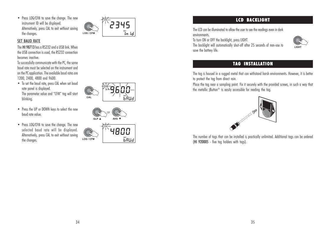
• Press LOG/CFM to save the change. The newinstrument ID will be displayed.Alternatively, press CAL to exit without savingthe changes.
SET BAUD RATE
The HI 98713 has a RS232 and a USB link. Whenthe USB connection is used, the RS232 connectionbecomes inactive.To successfully communicate with the PC, the samebaud rate must be selected on the instrument andon the PC application. The available baud rates are1200, 2400, 4800 and 9600.• To set the baud rate, press CAL when set baud
rate panel is displayed.The parameter value and “CFM” tag will startblinking.
• Press the UP or DOWN keys to select the newbaud rate value.
• Press LOG/CFM to save the change. The newselected baud rate will be displayed.Alternatively, press CAL to exit without savingthe changes.
LCD BACKL IGHTLCD BACKL IGHTLCD BACKL IGHTLCD BACKL IGHTLCD BACKL IGHT
The LCD can be illuminated to allow the user to see the readings even in darkenvironments.To turn ON or OFF the backlight, press LIGHT.The backlight will automatically shut-off after 25 seconds of non-use tosave the battery life.
TAG INSTALLATIONTAG INSTALLATIONTAG INSTALLATIONTAG INSTALLATIONTAG INSTALLATION
The tag is housed in a rugged metal that can withstand harsh environments. However, it is betterto protect the tag from direct rain.
Place the tag near a sampling point. Fix it securely with the provided screws, in such a way thatthe metallic iButton® is easily accessible for reading the tag.
The number of tags that can be installed is practically unlimited. Additional tags can be ordered(HI 920005 - five tag holders with tags).
36 37
For field measurements, HI 98713 is powered by 4 AA batteries.The battery life is enough for 3500 normal measurements.
When the instrument is started, the remaining battery life isestimated and reported in percents.
To preserve the battery it is better to use normal instead ofaveraged measurements.
Continuous measurements keep the LED on and should be usedwith caution if the battery life is an issue.
To further save the battery life, the instrument will turn offafter 15 minutes of non-use. The backlight will be turn offafter 25 seconds since the last key was pressed.
The battery life is measured each time the LED is turned onand if the remaining battery life is less than 10%, the batterytag will be displayed blinking on the LCD to warn the user thatthe batteries need to be replaced.
When the batteries are completely discharged, “0% bAtt” messagewill be displayed for one second and the instrument will turn off.
In order to use the instrument again, replace the batteries withnew ones or use an AC adapter.
BATTERIES MANAGEMENTBATTERIES MANAGEMENTBATTERIES MANAGEMENTBATTERIES MANAGEMENTBATTERIES MANAGEMENT
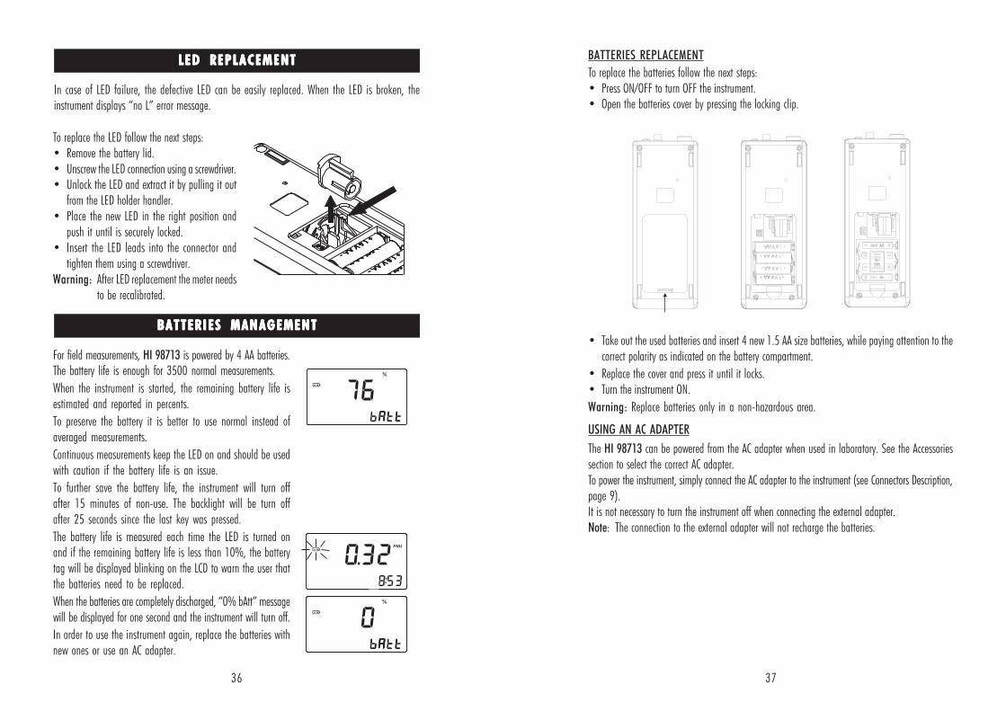
BATTERIES REPLACEMENT
To replace the batteries follow the next steps:• Press ON/OFF to turn OFF the instrument.• Open the batteries cover by pressing the locking clip.
• Take out the used batteries and insert 4 new 1.5 AA size batteries, while paying attention to thecorrect polarity as indicated on the battery compartment.
• Replace the cover and press it until it locks.• Turn the instrument ON.
Warning: Replace batteries only in a non-hazardous area.
USING AN AC ADAPTER
The HI 98713 can be powered from the AC adapter when used in laboratory. See the Accessoriessection to select the correct AC adapter.To power the instrument, simply connect the AC adapter to the instrument (see Connectors Description,page 9).It is not necessary to turn the instrument off when connecting the external adapter.Note: The connection to the external adapter will not recharge the batteries.
LED REPLACEMENTLED REPLACEMENTLED REPLACEMENTLED REPLACEMENTLED REPLACEMENT
In case of LED failure, the defective LED can be easily replaced. When the LED is broken, theinstrument displays “no L” error message.
To replace the LED follow the next steps:• Remove the battery lid.• Unscrew the LED connection using a screwdriver.• Unlock the LED and extract it by pulling it out
from the LED holder handler.• Place the new LED in the right position and
push it until is securely locked.• Insert the LED leads into the connector and
tighten them using a screwdriver.Warning: After LED replacement the meter needs
to be recalibrated.
38 39
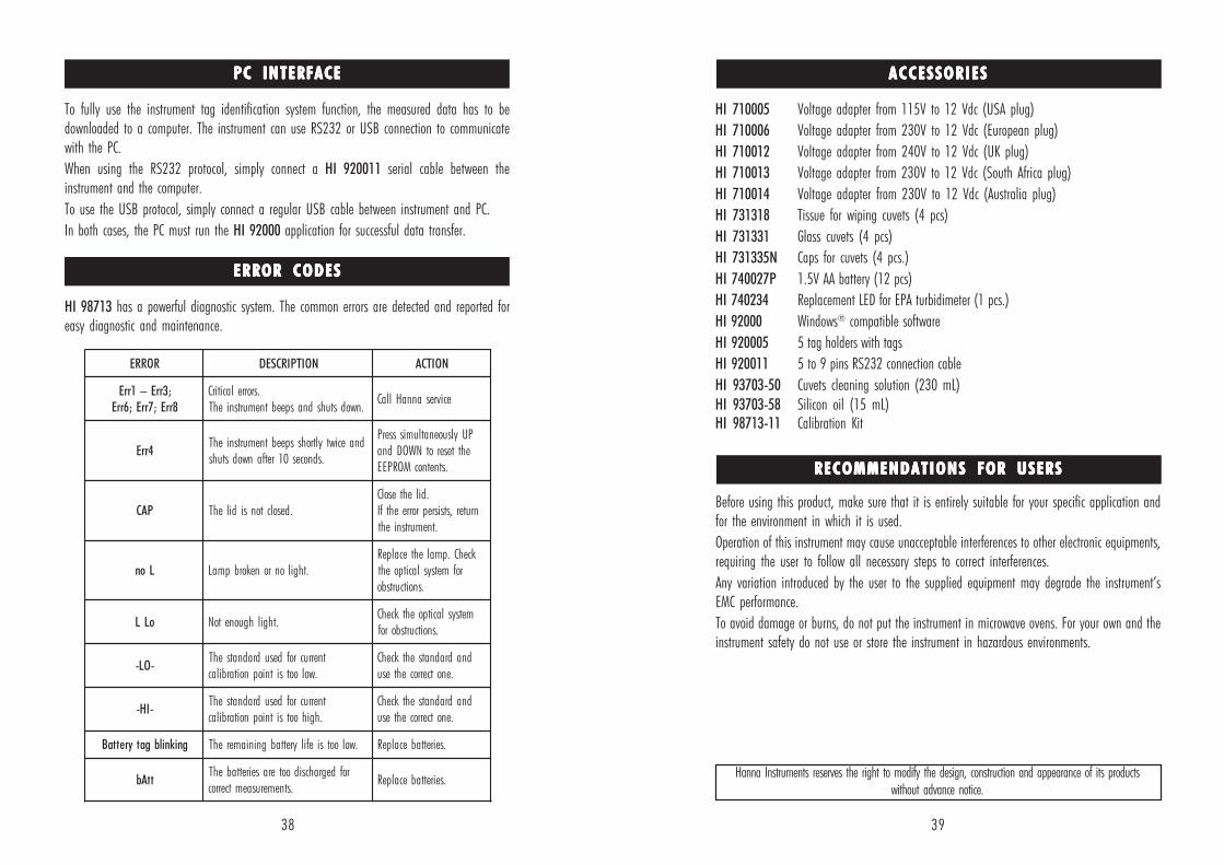
Before using this product, make sure that it is entirely suitable for your specific application andfor the environment in which it is used.
Operation of this instrument may cause unacceptable interferences to other electronic equipments,requiring the user to follow all necessary steps to correct interferences.
Any variation introduced by the user to the supplied equipment may degrade the instrument’sEMC performance.
To avoid damage or burns, do not put the instrument in microwave ovens. For your own and theinstrument safety do not use or store the instrument in hazardous environments.
HI 710005 Voltage adapter from 115V to 12 Vdc (USA plug)
HI 710006 Voltage adapter from 230V to 12 Vdc (European plug)
HI 710012 Voltage adapter from 240V to 12 Vdc (UK plug)
HI 710013 Voltage adapter from 230V to 12 Vdc (South Africa plug)
HI 710014 Voltage adapter from 230V to 12 Vdc (Australia plug)
HI 731318 Tissue for wiping cuvets (4 pcs)
HI 731331 Glass cuvets (4 pcs)
HI 731335N Caps for cuvets (4 pcs.)
HI 740027P 1.5V AA battery (12 pcs)
HI 740234 Replacement LED for EPA turbidimeter (1 pcs.)
HI 92000 Windows® compatible software
HI 920005 5 tag holders with tags
HI 920011 5 to 9 pins RS232 connection cable
HI 93703-50 Cuvets cleaning solution (230 mL)
HI 93703-58 Silicon oil (15 mL)HI 98713-11 Calibration Kit
ACCESSORIESACCESSORIESACCESSORIESACCESSORIESACCESSORIES
Hanna Instruments reserves the right to modify the design, construction and appearance of its productswithout advance notice.
RECOMMENDATIONS FOR USERSRECOMMENDATIONS FOR USERSRECOMMENDATIONS FOR USERSRECOMMENDATIONS FOR USERSRECOMMENDATIONS FOR USERS
ERROR CODESERROR CODESERROR CODESERROR CODESERROR CODES
HI 98713 has a powerful diagnostic system. The common errors are detected and reported foreasy diagnostic and maintenance.
RORRE NOITPIRCSED NOITCA
;3rrE–1rrE8rrE;7rrE;6rrE
.srorrelacitirC.nwodstuhsdnaspeebtnemurtsniehT
ecivresannaHllaC
4rrEdnaeciwtyltrohsspeebtnemurtsniehT
.sdnoces01retfanwodstuhs
PUylsuoenatlumissserPehtteserotNWODdna
.stnetnocMORPEE
PAC .desolctonsidilehT.dilehtesolC
nruter,stsisreprorreehtfI.tnemurtsnieht
Lon .thgilonronekorbpmaLkcehC.pmalehtecalpeR
rofmetsyslacitpoeht.snoitcurtsbo
oLL .thgilhguonetoNmetsyslacitpoehtkcehC
.snoitcurtsborof
-OL-tnerrucrofdesudradnatsehT
.wolootsitniopnoitarbilacdnadradnatsehtkcehC
.enotcerrocehtesu
-IH-tnerrucrofdesudradnatsehT
.hgihootsitniopnoitarbilacdnadradnatsehtkcehC
.enotcerrocehtesu
gniknilbgatyrettaB .wolootsiefilyrettabgniniamerehT .seirettabecalpeR
ttAbrofdegrahcsidooteraseirettabehT
.stnemerusaemtcerroc.seirettabecalpeR
PC INTERFACEPC INTERFACEPC INTERFACEPC INTERFACEPC INTERFACE
To fully use the instrument tag identification system function, the measured data has to bedownloaded to a computer. The instrument can use RS232 or USB connection to communicatewith the PC.
When using the RS232 protocol, simply connect a HI 920011 serial cable between theinstrument and the computer.
To use the USB protocol, simply connect a regular USB cable between instrument and PC.
In both cases, the PC must run the HI 92000 application for successful data transfer.
40
SALES AND TECHNICAL SERVICE CONTACTSSALES AND TECHNICAL SERVICE CONTACTSSALES AND TECHNICAL SERVICE CONTACTSSALES AND TECHNICAL SERVICE CONTACTSSALES AND TECHNICAL SERVICE CONTACTS
Australia:Tel. (03) 9769.0666 • Fax (03) 9769.0699
China:Tel. (10) 88570068 • Fax (10) 88570060
Egypt:Tel. & Fax (02) 2758.683
Germany:Tel. (07851) 9129-0 • Fax (07851) 9129-99
Greece:Tel. (210) 823.5192 • Fax (210) 884.0210
Indonesia:Tel. (210) 4584.2941 • Fax (210) 4584.2942
Japan:Tel. (03) 3258.9565 • Fax (03) 3258.9567
Korea:Tel. (02) 2278.5147 • Fax (02) 2264.1729
Malaysia:Tel. (603) 5638.9940 • Fax (603) 5638.9829
Singapore:Tel. 6296.7118 • Fax 6291.6906
South Africa:Tel. (011) 615.6076 • Fax (011) 615.8582
Taiwan:Tel. 886.2.2739.3014 • Fax 886.2.2739.2983
Thailand:Tel. (662) 619.0708 • Fax (662) 619.0061
United Kingdom:Tel. (01525) 850.855 • Fax (01525) 853.668
USA:Tel. (401) 765.7500 • Fax (401) 765.7575
For e-mail contacts and a complete list of Sales and Technical offices, please seewww.hannainst.com.
MA
N98713
09/07