Embed Size (px)
Citation preview

IVQs in Engineering (2565)
Level 2 IVQ Technician Certificate in Engineering – Mechanical Engineering– Mechanical, Electrical and Electronic Engineering– Electrical and Electronic Engineering(2565-01) (500/5760/1)
Qualification handbook for centres
www.cityandguilds.com
September 2009
Version 2.0

Publications and enquiries
City & Guilds publications are available from
Publications Sales
City & Guilds
1 Giltspur Street
London
EC1A 9DD
United Kingdom
T +44 (0)20 7294 2850
F +44 (0)20 7294 2413
General information about City & Guilds may be obtained from Customer Relations at the above address or on +44 (0)20 7294 2787 or by [email protected].
Equal opportunities
City & Guilds fully supports the principle of equal opportunities and we are committed to satisfying this principle in all our activities and published material.
Every effort has been made to ensure that the information contained in this publication is true and correct at the time of going to press. However, City & Guilds’ products and services are subject to continuous development and improvement and the right is reserved to change products and services from time to time. City & Guilds cannot accept liability for loss or damage arising from the use of information in this publication.
©2003 The City and Guilds of London Institute. All rights reserved.City & Guilds is a trademark of the City and Guilds of London Institute.
1 Giltspur Street
London
EC1A 9DD
T +44 (0)20 7294 2468
F +44 (0)20 7294 2400
www.cityandguilds.com

IVQs in Engineering (2565)
Level 2 IVQ Technician Certificate in Engineering – Mechanical Engineering– Mechanical, Electrical and Electronic Engineering– Electrical and Electronic Engineering(2565-01) (500/5760/1)
Qualification handbook for centres
ST00029381/09.09/PO4500055960

[ This page is intentionally blank ]
05 Important notice
07 Levels of City & Guilds qualifications
09 IVQ in Engineering 2565
09 About City & Guilds
09 Introduction to this programme
09 Certificate
09 Diploma
09 Advanced diploma
09 Full Technological Diploma
09 Making entries for assessments
09 Internal candidates
09 External candidates
09 Resources
10 Assessments
10 Certificate
10 Award number
10 Component numbers
10 Technician Certificate in Applied Mechanical Engineering
10 Technician Certificate in Mechanical Engineering Theory
11 Technician Certificate in Applied Mechanical, Electrical andElectronic Engineering
11 Technician Certificate in Mechanical, Electrical and Electronic Engineering Theory
11 Technician Certificate in Applied Electrical and Electronic Engineering
11 Technician Certificate in Electrical and Electronic Engineering Theory
12 Results and certification
12 How to offer this programme
12 Subject approval
12 Examination centre approval
12 Other information
12 Designing courses of study
13 Presentation format of units
13 Practical competences
13 Knowledge requirements
13 Practical assignments
13 Entry levels
13 Progression routes and recognition
13 Useful publications
15 Syllabus
IVQ in Engineering 2565
16 001 Engineering Fundamentals 1
23 Assessment
24 002 Engineering Fundamentals 1 Practical Assignments
66 003 Mechanical Technology
69 Assessment
70 004 Mechanical Technology Practical Assignments
79 005 Electrical and Electronic Applications
83 Assessment
84 006 Electrical and Electronic Applications Practical Assignments
101 Appendix A
Entry level mathematics
101 Introduction
101 Knowledge requirements
101 Numeracy
101 Algebra
101 Geometry
101 Graphs
103 Appendix B
Practical assignments
103 Practical assignments
103 Instructor notes
103 Candidate instructions
103 Marking
103 Supervision
103 Records, results and certification
103 Visiting verifier
Contents

[ This page is intentionally blank ]

Important notice
Following the accreditation of the Technician IVQs in Engineering(2565) on the National Qualifications Framework of England,Wales and Northern Ireland (NQF), some changes have beenmade to the qualification, at the request of the Office of theQualifications and Examinations Regulator (Ofqual), thequalifications regulator in England.
These changes took effect on 1 June 2009 and are outlined on pages 05–06.
Note: the content of the qualifications has not changed following accreditation.
Changes to the qualification titles
The qualification titles have changed as follows:
Technician Certificate in Engineering – Applied MechanicalEngineering (2565-01)changed toLevel 2 IVQ Technician Certificate in Engineering
(Mechanical) (2565-01)
Accreditation number: 500/5760/1
Technician Certificate in Engineering – Applied Mechanical,Electrical and Electronic Engineering (2565-01)changed toLevel 2 IVQ Technician Certificate in Engineering
(Mechanical, Electrical and Electronic) (2565-01)
Accreditation number: 500/5760/1
Technician Certificate in Engineering – Applied Electrical andElectronic Engineering (2565-01)changed toLevel 2 IVQ Technician Certificate in Engineering
(Electrical and Electronic) (2565-01)
Accreditation number: 500/5760/1
Changes to the unit titles
Following the accreditation of the Technician IVQs in Engineering,each unit has been given an accreditation reference numberwhich will appear on the Certificate of Unit Credit.
The content of the units is unchanged.
Level 2 IVQ Technician Certificate in Engineering
(Mechanical) (2565-01)
Accreditation number: 500/5760/1
D/502/2560 – Engineering Fundamentals 1H/502/2561 – Engineering Fundamental 1 Practical AssignmentsK/502/2562 – Mechanical TechnologyM/502/2563 – Mechanical Technology Practical Assignments
Level 2 IVQ Technician Certificate in Engineering
(Mechanical, Electrical and Electronic) (2565-01)
Accreditation number: 500/5760/1
D/502/2560 – Engineering Fundamentals 1H/502/2561 – Engineering Fundamental 1 Practical AssignmentsK/502/2562 – Mechanical TechnologyT/502/2564 – Electrical and Electronic ApplicationsA/502/2565 – Electrical and Electronic Applications PracticalAssignmentsM/502/2563 – Mechanical Technology Practical Assignments
Level 2 IVQ Technician Certificate in Engineering
(Electrical and Electronic) (2565-01)
Accreditation number: 500/5760/1
D/502/2560 – Engineering Fundamentals 1H/502/2561 – Engineering Fundamental 1 Practical AssignmentsT/502/2564 – Electrical and Electronic ApplicationsA/502/2565 – Electrical and Electronic Applications Practical
Regulations: 1998 edition 05

Registration for theory examination
Registration process for the theory examination has not changed.
Result submission for practical assessment
Result submission process for the practical assessments has not changed.
Change to the grading
The grade ‘Credit’ has been changed to ‘Merit’. All other grades areunchanged. The content of the units concerned is also unchanged.
Notification of Candidate Results (NCR) and Certificate
of Unit Credit (CUC)
Notification of Candidate Results (NCR) and Certificate of UnitCredit (CUCs) continue to be available on completion of eachassessment (theory or practical).
Final certificate will be issued on successful completion of all the required assessments.
‘Theory only’ routes
The ‘Theory only’ routes continue to be available as unaccredited qualifications.
Changes to the certificate layout
Certificates issued on completion of an accredited IVQ show theaccredited title and the accreditation number for the qualification.The level in the accredited title refers to the NQF level thequalification is accredited at.
The certificate also lists all the units achieved, including the gradeand the unit accreditation number.
The certificate carries the logos of the regulatory authorities in England, Wales and Northern Ireland indicating that the NQF accreditation only applies to these countries.
IVQ in Engineering 256506
Regulations: 1998 edition 07
Levels of City & Guilds qualifications
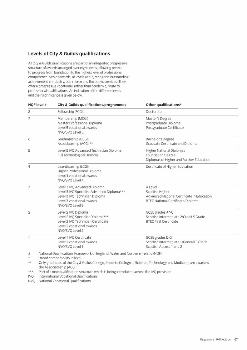
All City & Guilds qualifications are part of an integrated progressivestructure of awards arranged over eight levels, allowing people to progress from foundation to the highest level of professionalcompetence. Senior awards, at levels 4 to 7, recognise outstandingachievement in industry, commerce and the public services. Theyoffer a progressive vocational, rather than academic, route toprofessional qualifications. An indication of the different levels and their significance is given below.
NQF level# City & Guilds qualifications/programmes Other qualifications*
8 Fellowship (FCGI) Doctorate
7 Membership (MCGI) Master’s DegreeMaster Professional Diploma Postgraduate DiplomaLevel 5 vocational awards Postgraduate Certificate NVQ/SVQ Level 5
6 Graduateship (GCGI) Bachelor’s DegreeAssociateship (ACGI)** Graduate Certificate and Diploma
5 Level 5 IVQ Advanced Technician Diploma Higher National DiplomasFull Technological Diploma Foundation Degree
Diplomas of Higher and Further Education
4 Licentiateship (LCGI) Certificate of Higher Education Higher Professional DiplomaLevel 4 vocational awardsNVQ/SVQ Level 4
3 Level 3 IVQ Advanced Diploma A LevelLevel 3 IVQ Specialist Advanced Diploma*** Scottish Higher Level 3 IVQ Technician Diploma Advanced National Certificate in Education Level 3 vocational awards BTEC National Certificate/DiplomaNVQ/SVQ Level 3
2 Level 2 IVQ Diploma GCSE grades A*-CLevel 2 IVQ Specialist Diploma*** Scottish Intermediate 2/Credit S GradeLevel 2 IVQ Technician Certificate BTEC First Certificate Level 2 vocational awardsNVQ/SVQ Level 2
1 Level 1 IVQ Certificate GCSE grades D-GLevel 1 vocational awards Scottish Intermediate 1/General S GradeNVQ/SVQ Level 1 Scottish Access 1 and 2
# National Qualifications Framework of England, Wales and Northern Ireland (NQF)* Broad comparability in level** Only graduates of the City & Guilds College, Imperial College of Science, Technology and Medicine, are awarded
the Associateship (ACGI)*** Part of a new qualification structure which is being introduced across the IVQ provisionIVQ International Vocational QualificationsNVQ National Vocational Qualifications

[ This page is intentionally blank ]

About City & Guilds
We provide assessment and certification services for schools and colleges, business and industry, trade associations andgovernment agencies in more than 100 countries. We have over118 years of experience in identifying training needs, developingassessment materials, carrying out assessments and trainingassessment staff. We award certificates to people who haveshown they have mastered skills that are based on world-classstandards set by industry. City & Guilds International provides a particular service to customers around the world who need high-quality assessments and certification.
Introduction to this programme
We have designed the Technician Awards in Engineeringprogramme for those undergoing training or employed in thisarea of work. The programme aims to reflect the internationalnature of the knowledge and skills and activities needed fordifferent countries or cultures.
We do not say the amount of time a candidate would need tocarry out the programme, but we do provide advice on guidedlearning hours for each unit at each level (see below). Theprogramme has three related levels.
Certificate
The certificate (about 300-450 guided learning hours) provides a broad introduction to the theory and practical sides ofengineering for a front-line worker or a person beginning anacademic training programme.
Diploma
The diploma (about 600 guided learning hours) provides more practice involving a broader range of skills appropriate to a person who may also supervise, or who is going on intohigher education.
Advanced Diploma
The advanced diploma (about 600 guided learning hours) takesthese skills to the level appropriate for a person preparing for or working in first-level management. It is also appropriate forsomeone who wants to receive specialised training at a high level.
We stress that these figures are only a guideline and that weaward certificates and diplomas for gaining and showing skills by whatever mode of study, and not for periods of time spent in study.
We provide certificates for all work-related areas at seven levels within our structure of awards shown in appendix C. This programme covers level 2. The standards and assessmentsfor the diploma (level 3) and the advanced diploma (level 4) arepublished separately.
Full Technological Diploma
We will award the Full Technological Diploma (FTD) in Engineeringto someone who is at least 21, who has had at least two yearsrelevant industrial experience, and who has successfully finishedthe assessments for the diploma and advanced diploma levels of this award. If candidates enter for this diploma, they must alsosend us a portfolio of evidence to support their application.
Making entries for assessments
Candidates can only be entered for the assessments in this subject if the approved examination centres agree. Candidates must enter through an examination centre we have approved to carry out the assessments for 2565 TechnicianAwards in Engineering.
There are two ways of entering candidates for assessments.
Internal candidates
Candidates can enter for examinations if they are taking or havealready finished a course at a school, college or similar traininginstitution that has directed their preparation whether by going to a training centre, working with another institution, or by openlearning methods.
External candidates
These are candidates who have not finished a programme asdescribed above. The examination centres must receive theirapplication for entry well before the date of the examinationconcerned. This allows them to act on any advice you give aboutassessment arrangements or any further preparation needed.External candidates must carry out practical assignments andprojects if necessary, and they will need extra time and guidanceto make sure that they meet all the requirements for this part ofthe assessment.
In this publication we use the term ‘centre’ to mean a school,college, place of work or other institution.
Resources
If you want to use this programme as the basis for a course, youmust read this booklet and make sure that you have the staff andequipment to carry out all parts of the programme. If there are nofacilities for realistic practical work, we strongly recommend thatyou develop links with local industry to provide opportunities forhands-on experience.
Technician Awards in Engineering 2565
Regulations: 1998 edition 09
Assessments
There is one level of Technician Certificate Award in Engineering.
Certificate
We use a numbering system to allow entries to be made for ourawards. The numbers used for this programme are as follows.
Award number
2565-01 Technician Certificate in Applied Mechanical Engineering
Technician Certificate in Mechanical Engineering Theory
Technician Certificate in Applied Mechanical, Electricaland Electronic Engineering
Technician Certificate in Mechanical, Electrical andElectronic Engineering Theory
Technician Certificate in Applied Electrical and ElectronicEngineering
Technician Certificate in Electrical and ElectronicEngineering Theory
We use award numbers to describe the subject and level of the award.
Component numbers
001 Engineering Fundamentals 1002 Engineering Fundamentals 1Practical Assignments003 Mechanical Technology004 Mechanical Technology Practical Assignments005 Electrical and Electronic Applications006 Electrical and Electronic Applications Practical
Assignments
We use component numbers to show units for which we mayaward a certificate of unit credit.
We use these numbers throughout this booklet. You must usethese numbers correctly if you send forms to us.
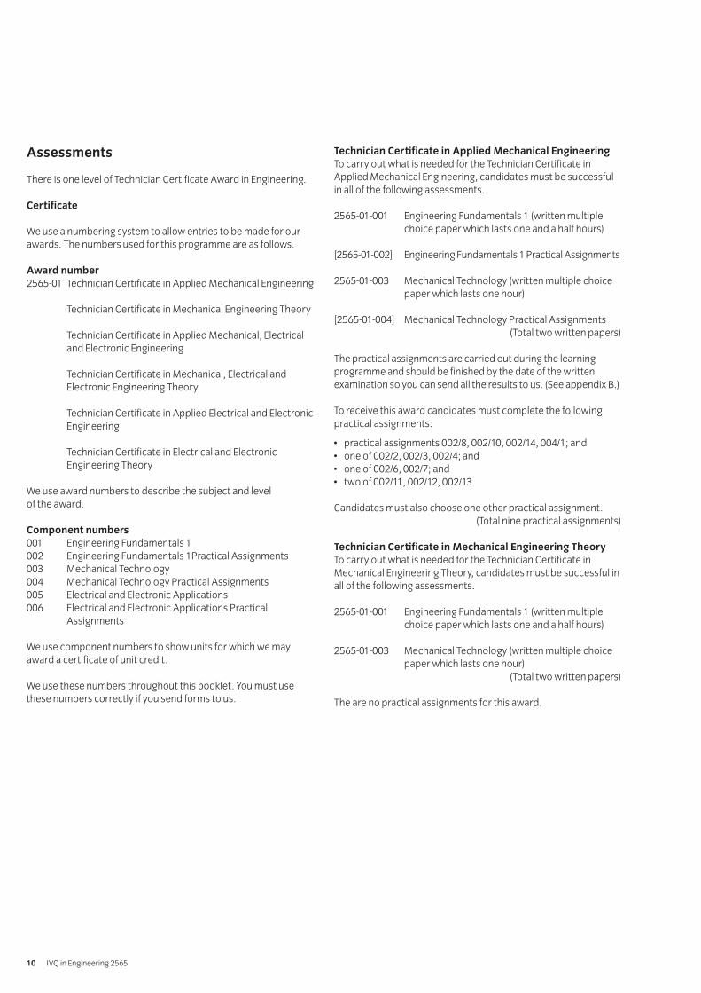
Technician Certificate in Applied Mechanical Engineering
To carry out what is needed for the Technician Certificate inApplied Mechanical Engineering, candidates must be successfulin all of the following assessments.
2565-01-001 Engineering Fundamentals 1 (written multiplechoice paper which lasts one and a half hours)
[2565-01-002] Engineering Fundamentals 1 Practical Assignments
2565-01-003 Mechanical Technology (written multiple choicepaper which lasts one hour)
[2565-01-004] Mechanical Technology Practical Assignments(Total two written papers)
The practical assignments are carried out during the learningprogramme and should be finished by the date of the writtenexamination so you can send all the results to us. (See appendix B.)
To receive this award candidates must complete the followingpractical assignments:
• practical assignments 002/8, 002/10, 002/14, 004/1; and• one of 002/2, 002/3, 002/4; and• one of 002/6, 002/7; and• two of 002/11, 002/12, 002/13.
Candidates must also choose one other practical assignment.(Total nine practical assignments)
Technician Certificate in Mechanical Engineering Theory
To carry out what is needed for the Technician Certificate inMechanical Engineering Theory, candidates must be successful inall of the following assessments.
2565-01-001 Engineering Fundamentals 1 (written multiplechoice paper which lasts one and a half hours)
2565-01-003 Mechanical Technology (written multiple choicepaper which lasts one hour)
(Total two written papers)
The are no practical assignments for this award.
IVQ in Engineering 256510
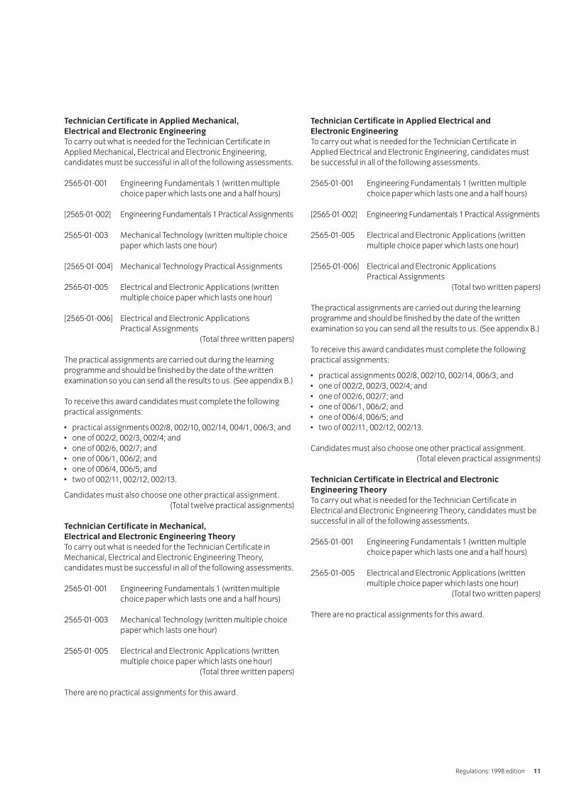
Technician Certificate in Applied Mechanical,
Electrical and Electronic Engineering
To carry out what is needed for the Technician Certificate inApplied Mechanical, Electrical and Electronic Engineering,candidates must be successful in all of the following assessments.
2565-01-001 Engineering Fundamentals 1 (written multiplechoice paper which lasts one and a half hours)
[2565-01-002] Engineering Fundamentals 1 Practical Assignments
2565-01-003 Mechanical Technology (written multiple choicepaper which lasts one hour)
[2565-01-004] Mechanical Technology Practical Assignments
2565-01-005 Electrical and Electronic Applications (writtenmultiple choice paper which lasts one hour)
[2565-01-006] Electrical and Electronic ApplicationsPractical Assignments
(Total three written papers)
The practical assignments are carried out during the learningprogramme and should be finished by the date of the writtenexamination so you can send all the results to us. (See appendix B.)
To receive this award candidates must complete the followingpractical assignments:
• practical assignments 002/8, 002/10, 002/14, 004/1, 006/3; and• one of 002/2, 002/3, 002/4; and• one of 002/6, 002/7; and• one of 006/1, 006/2; and• one of 006/4, 006/5; and• two of 002/11, 002/12, 002/13.
Candidates must also choose one other practical assignment.(Total twelve practical assignments)
Technician Certificate in Mechanical,
Electrical and Electronic Engineering Theory
To carry out what is needed for the Technician Certificate inMechanical, Electrical and Electronic Engineering Theory,candidates must be successful in all of the following assessments.
2565-01-001 Engineering Fundamentals 1 (written multiplechoice paper which lasts one and a half hours)
2565-01-003 Mechanical Technology (written multiple choicepaper which lasts one hour)
2565-01-005 Electrical and Electronic Applications (writtenmultiple choice paper which lasts one hour)
(Total three written papers)
There are no practical assignments for this award.
Technician Certificate in Applied Electrical and
Electronic Engineering
To carry out what is needed for the Technician Certificate inApplied Electrical and Electronic Engineering, candidates must be successful in all of the following assessments.
2565-01-001 Engineering Fundamentals 1 (written multiplechoice paper which lasts one and a half hours)
[2565-01-002] Engineering Fundamentals 1 Practical Assignments
2565-01-005 Electrical and Electronic Applications (writtenmultiple choice paper which lasts one hour)
[2565-01-006] Electrical and Electronic Applications Practical Assignments
(Total two written papers)
The practical assignments are carried out during the learningprogramme and should be finished by the date of the writtenexamination so you can send all the results to us. (See appendix B.)
To receive this award candidates must complete the followingpractical assignments:
• practical assignments 002/8, 002/10, 002/14, 006/3; and• one of 002/2, 002/3, 002/4; and• one of 002/6, 002/7; and• one of 006/1, 006/2; and• one of 006/4, 006/5; and• two of 002/11, 002/12, 002/13.
Candidates must also choose one other practical assignment.(Total eleven practical assignments)
Technician Certificate in Electrical and Electronic
Engineering Theory
To carry out what is needed for the Technician Certificate inElectrical and Electronic Engineering Theory, candidates must besuccessful in all of the following assessments.
2565-01-001 Engineering Fundamentals 1 (written multiplechoice paper which lasts one and a half hours)
2565-01-005 Electrical and Electronic Applications (writtenmultiple choice paper which lasts one hour)
(Total two written papers)
There are no practical assignments for this award.
Regulations: 1998 edition 11

We provide assessments in two ways.
a Fixed date
These are assessments which are carried out on dates andtimes we set. These assessments have no brackets around their numbers.
b Free date
These are assignments which are carried out at a college orother training establishment on a date or over a period whichthe college chooses. These assessments have brackets aroundtheir numbers.
In this programme the written assessments are fixed date. Thepractical assessments and the projects are free date.
You must carry out assessments according to our InternationalDirectory of Examinations and Assessments. If there are anydifferences between information in this publication and the currentdirectory, the Directory has the most up-to-date information.
Results and certification
Everyone who enters for our certificates, diplomas, and advanceddiplomas receives a ‘Notification of Candidate Results’ givingdetails of how they performed.
If candidates successfully finish any assessment within thisprogramme (for example, any one of the examination papers)they will receive a certificate of unit credit towards the certificateor diploma for which they are aiming. We grade course workassessments as pass or fail. We grade written assessments on the basis of fail, pass, credit or distinction. The certificate of unitcredit will not mention assessments which they do not enter,which they failed or from which they were absent.
Each certificate or diploma clearly states what candidates need for full certification at the relevant level, allowing schools,colleges and employers to see whether they have met the full requirements.
If candidates successfully finish all the requirements for a fullcertificate or a diploma, they will automatically receive theappropriate certificate.
We will send the ‘Notification of Candidate Results’, certificates of unit credit, certificates, diplomas and advanced diplomas tothe examination centre to be awarded to successful candidates. It is your responsibility to give the candidates the certificates. If candidates have a question about the results and certificates,they must contact you. You may then contact us if necessary.
We will also send you a results list showing how all candidates performed.
How to offer this programme
To offer this programme you must get approval from us. There aretwo categories of approval.
Subject approval
We give approval to offer a teaching course based on this syllabus.
Examination centre approval
We give approval to enter candidates for examinations.
To be approved by us to offer a teaching course you must send usthe application form.
To enter candidates for examinations you must be approved byus as an examination centre. For this programme it is possible toact as a registered examination centre only, and accept externalcandidates. Approved examination centres must provide suitablefacilities for taking examinations, secure places to keep theexamination papers and materials, and may have an appointedvisiting verifier to review practical work.
After we have received and accepted an application, we will sendan approval letter confirming this. You can then send entries in atany time using the International Directory of Examinations andAssessments for guidance.
Please note that in this section we have provided an
overview of centre approval procedures. Please
refer to the current issue of ‘Delivering International
Qualifications – Centre Guide’ for full details of each
aspect of these procedures.
Other informationDesigning courses of studyCandidates for the various Technician Awards in Engineering will have come from different backgrounds and will have different employment and ̀ training experiences. We recommendthe following:
• carry out an assessment of the candidates’ achievements soyou can see what learning they already have and decide thelevel of entry they will need; and
• consider what learning methods and places will best suit them.
When you assess a candidate’s needs, you should designteaching programmes that consider:
• what, if any, previous education qualifications or training thecandidate has, especially in the various general vocationaleducation certificates we provide; and
• what, if any, previous practical experience the candidate haswhich is relevant to the aims of the programme and from whichthey may have learned the relevant skills and knowledge.
When you choose learning methods and places, you shouldconsider the results of your assessments and whether thefollowing are available.
IVQ in Engineering 256512
• Open or distance learning material.• Workplace learning that can be carried out on site or between
you and a local workplace. This will allow the candidates accessto specialised equipment and work experience.
• Working with other registered centres to share facilities.• Opportunities for co-operative learning between candidates for
different certificates who need to gain similar skills.
As long as the candidates meet the aims of this learningprogramme the structures of courses of study are up to you. So, it is possible to include extra topics that meet local needs.
You should avoid teaching theory alone. As far as possible thepractical work should be closely related to work in the classroomso that candidates use their theory in a realistic work environment.You can use formal lectures in the classroom with appropriateexercises and demonstrations. Candidates should keep records of the practical work they do so they can refer to it at a later date.
We assume that you will include core skills, such as numeracy,communication, working with people, and organisation andplanning throughout a teaching programme.
Presentation format of unitsPractical competences
Each unit starts with a section on practical competences whichshows the practical skills candidates must have.
At times we give more detail about important words in each‘competence statement’.
For example
4.1 Select in terms of properties, ease of handling, availability,form of supply (eg round, square, sheet, plate) and cost,suitable materials for given mechanical and electricalcomponents, using appropriate data sources.Sources: text books, catalogues, standards (BS/ISO), datasheets, computer database.’
In the above statement the word ‘sources’ is given as a rangewhich the candidate should be familiar with. Candidates should cover the complete range. When a range starts with the abbreviation ‘eg’ the candidates only need to cover some of the ranged areas or you can use suitable alternatives.
Knowledge requirements
Immediately after the section on practical competences the unittells you what knowledge is needed for that area. The knowledgeneeded is closely linked to the practical competences, so it is bestto teach the two together so that the candidate appreciates thetopic more.
Practical assignments
You should make sure all practical assignments are supervisedand instructors should make sure that the results reflect thecandidate’s own work. You must hold all the documents andmaterial in a file (portfolio) for each candidate for eight weeksafter the application for a certificate. You must also keep separaterecords of the dates of all attempts by each candidate.
Entry levels
We consider the following programmes to be relevantpreparation for this programme.
Background to Technology (3660)Numeracy (3750)Entry Level Mathematics (see appendix A)
We also consider the following Pitman Qualifications award asrelevant alongside this programme.
English for Speakers of Other Languages – higher intermediate level
If candidates do not have the above qualifications, they shouldhave secondary school leaving passes in English and mathematics.
Progression routes and recognition
We consider the following programmes to be relevantprogression routes from this programme.
Diploma Awards in Engineering (2565)Advanced Diploma Awards in Engineering (2565)
A number of UK universities and other higher-education institutionswill accept success at diploma or advanced diploma level of thisprogramme for direct entry onto higher-level programmes. Thedecision to accept a candidate on to a degree programme, and the level of entry, is up to the institution. We provide details oforganisations recognising achievement in this programme.
Useful publications
We can provide a list of suggested text books covering specificareas of this programme. We may also have knowledge aboutother support materials. You should make sure that you have the latest information. We will automatically send updated lists to centres we have approved to offer this programme.
Plain English Campaign’s Crystal Mark only covers the Technician Awards in Engineering regulations.
Regulations: 1998 edition 13

[ This page is intentionally blank ]

Sections
Component numbers
001 Engineering Fundamentals 1
002 Engineering Fundamentals 1 – Practical Assignments
003 Mechanical Technology
004 Mechanical Technology – Practical Assignments
005 Electrical and Electronic Applications
006 Electrical and Electronic Applications – Practical Assignments
SyllabusIVQ in Engineering 2565
Syllabus: 1998 edition 15
Mathematics
Practical competences
The candidate must be able to do the following:
Statistics
1.1 Conduct a survey and record data by means of a tally chartand produce the results in the form of a frequency table.
1.2 Represent the information contained in the frequencytable in pictorial form.Pictorial form: pie charts, bar charts and line graphs
1.3 Define arithmetic mean, the mode and the median andcalculate their values from the distribution obtained.
Knowledge requirements
Instructors must ensure that candidates are able to:
Number systems
1.4 Express denary numbers in binary forms and binarynumbers in denary forms.
1.5 Perform simple calculations involving addition,subtraction, multiplication and division of binary numbers.
Indices
1.6 Perform calculations applying rules of indices where m andn are positive integers.
Rules: aman = am+n, = am-n, (am)n = amn
1.7 State that a° = 1 for all values of a.
1.8 Apply the rules where m and n are negative integers.
Rules: aman = am+n, am/an = am-n, (am)n = amn
1.9 Apply the rules for fractional indices where n and m arepositive integers, and recognise that
a1/n = n√–a and that am/n = n
√–am
1.10 Evaluate expressions which combine positive, negativeand fractional indices.
Algebra
1.11 Factorise expressions by grouping and extraction of common factors.
1.12 Distinguish between an algebraic expression, an equationand an identity.
1.13 Maintain the equality of a given equation whilst applyingany arithmetic operation.
1.14 Solve linear equations in one unknown including thoseinvolving brackets and fractions.
1.15 Form and solve linear equations.
1.16 Solve a pair of simultaneous linear equations in twounknowns by both substitution and elimination.
1.17 Evaluate formulae required in this and parallel units bysubstitution of given data.
1.18 Transpose simple formulae in which the subject is equal toan expression whose terms are connected by + or –
1.19 Transpose simple formulae in which the subject is equal toan expression composed of two or more factors.
1.20 Transpose formulae which contain a root or power.
1.21 Transpose formulae in which the subject appears in morethan one term.
1.22 Transpose formulae and evaluate using given data.
Geometry and trigonometry
1.23 Use given formulae to calculate areas and perimeters ofplane figures.Plane figures: triangle, square, rectangle, parallelogram,circle, semi-circle
1.24 Use given formulae to calculate the surface area andvolume of common solids.Common solids: cubes, prisms, cylinders, pyramid, cone, sphere
1.25 Demonstrate by suitable examples that the ratio of theareas of similar shapes is equal to the square of the ratio ofthe corresponding linear dimensions.
1.26 Demonstrate by suitable examples that the ratio of thevolumes of similar solids is equal to the cube of the ratio ofcorresponding linear dimensions.
1.27 State the angle sum of a triangle.
1.28 Identify the types of triangle.Types: acute-angled, right-angled, obtuse-angled,equilateral, isosceles
1.29 Identify complementary angles.
1.30 Calculate the length of any third side of a right-angledtriangle, given the length of the other two sides, using thetheorem of Pythagoras.
1.31 Demonstrate, by suitable examples, that any triangle whosesides are in the ratios 3:4:5 forms a right-angled triangle.
1.32 Compare two triangles for similarity or congruency.
am
an
001 Engineering Fundamentals 1
IVQ in Engineering 256516
1.33 Determine an unknown side or an angle of a secondtriangle applying principles demonstrated in 1.32.
1.34 Define trigonometrical ratios and solve problems involvingright angled triangles.Ratios: sine, cosine, tangent
1.35 Identify components of a circle.Components: radius, diameter, circumference, chord,tangent, secant, sector, segment, arc
1.36 Solve simple problems relating to circumference, radiusand diameter of circles.
1.37 State that the angle between a tangent and the radius of acircle at the point of contact is a right-angle.
1.38 State the relationships between the internal angles formedby two radii and the tangents at the points of contact withthe circumference of a circle.
1.39 Define the radian in terms of π
1.40 Convert degree measure to radians and vice versa.
Graphs
1.41 Choose suitable scales and plot graphs from experimental data.
1.42 Plot graphs of equations by forming a data table andplotting the points.Equations: y = mx + c, y = 1/x, y = x2
1.43 Read values from graphs and interpolate intermedialvalues between points.
1.44 Determine the intercept of a straight line on the y – axis byextrapolation.
1.45 Determine the gradient of a straight line graph.
1.46 Evaluate the law of a straight line graph in the form of y = mx + c
1.47 Determine the roots of a quadratic equation from theintersections of the graph with the x – axis.
1.48 Solve graphically a pair of simultaneous equations in twounknowns.
Science
Practical competences
The candidate must be able to do the following:
Dynamics
1.49 Construct distance/time graphs from measured data, andinterpret slopes as speed or velocity.
1.50 Construct velocity/time graphs from measured data andinterpret slopes as acceleration.
Electricity
1.51 Use a tungsten filament lamp, ammeter, voltmeter andvariable resistors to demonstrate the effect of temperatureon resistance.
Heat
1.52 Use a calorimeter to determine the specific heat capacityof a liquid.
Knowledge requirements
Instructors must ensure that candidates are able to:
SI Units and symbols
1.53 Identify basic SI units.SI units: metre(m), kilogramme(kg), second(s), ampere(A),kelvin(K)
1.54 Identify names and symbols for preferred SI prefixes.Names and symbols: giga(G), mega(M), kilo(k), micro(μ),nano(n) and pico(p)
Dynamics
1.55 Define speed, velocity and acceleration.
1.56 Describe waves and wave motion.Waves: sound waves, electromagnetic waves
1.57 Define amplitude, wavelength(λ), frequency(f) and the unitof frequency (hertz).
1.58 State the relationship velocity = frequency x wavelength (v = fλ).
1.59 Define momentum and state Newton’s laws of motion.
1.60 State the relationship between force (f), mass (m) andacceleration (a).
1.61 Define the unit of force as the newton (N) and explain therelationship between weight and mass.
Syllabus: 1998 edition 17

1.62 Solve problems involving Newton’s laws of motion.
1.63 Define work and power and the units used.Units: Joule (J), Watt (W)
1.64 Explain the relationship between work and energy.
1.65 Explain efficiency and solve problems involving work done by a constant force, power and efficiency.
1.66 Identify forms of energy.Forms: mechanical (potential and kinetic), heat, chemical, electrical
1.67 Explain the principle of conservation of energy and energy conversion.Energy conversion: electrical to heat, electrical tochemical, electrical to mechanical, mechanical toelectrical, mechanical to heat
Statics
1.68 Represent force as a vector.
1.69 Explain the concept of equilibrium.
1.70 Explain the triangle of forces theorem and solve graphicallyproblems using the triangle of forces theorem.
1.71 Explain the parallelogram of forces theorem and solvegraphically problems involving the resultant andequilibrium of two inclined forces.
1.72 Define the moment of a force about a point.
1.73 Explain the principle of moments and solve problemsinvolving straight and bell crank levers.
1.74 Define the centre of gravity and identify the position of thecentre of gravity of symmetrically- shaped solids.
1.75 Define pressure and its units (N/m2 or Pa).
1.76 Explain the distinction between absolute and gaugepressure.
1.77 Calculate pressure in engineering situations.
Heat
1.78 Explain the difference between heat and temperature.
1.79 Describe the methods of heat transfer.Methods: conduction, convection, radiation
1.80 Describe the Celsius scale of temperature and explain therelationship between degrees Celsius (C) and Kelvin (K).
1.81 Define specific heat capacity and its units.
1.82 Calculate heat transfer in mixtures of hot and coldsubstances, involving their mass, specific heat capacityand temperature changes.
1.83 Describe with the aid of a temperature time graph thephase changes that occur when superheated steam isformed from ice by the uniform supply of heat energy.
1.84 Define specific latent heats of fusion and vapourisation andsolve problems involving phase changes.
1.85 Define the coefficient of linear expansion and its units andsolve problems involving the expansion and contraction ofengineering components.
Electricity
1.86 Describe the effects of an electric current.Effects: heating, chemical, magnetic
1.87 Describe the basic concept of a flow of electric current.
1.88 Define the coulomb, ampere, ohm and volt.
1.89 State Ohm’s law and use the law to solve simple electricalcircuit problems.
1.90 Identify the formula for power in a resistive electric circuit(power = voltage x current).
1.91 Identify the formula for energy in a resistive electric circuit(energy = power x time).
1.92 Explain the concept of a magnetic field.
1.93 Explain the principle of operation of electromagnet devices.Electromagnetic devices: lifting magnet, relay andelectric bell
1.94 Explain the concept of an electric field.
DrawingAll drawings should comply with BS308 or equivalent ISO
standards. Electrical and electronic drawings should
comply with BS3939 or equivalent ISO standards.
Practical competences
The candidates must be able to do the following:
Isometric drawing, oblique drawing and freehand sketching
1.95 Interpret isometric and oblique views.
1.96 Use an appropriate method to draw an isometric circle.
IVQ in Engineering 256518

1.97 Produce isometric drawings (without the use of isometricscales) and oblique drawings from given orthographicdrawings of simple mechanical and electrical components.
1.98 Produce freehand orthographic and pictorial sketches ofsimple mechanical and electrical components usingsquare grid paper.
Orthographic working drawings
1.99 Produce detail drawings in first or third angle projection ofsimple mechanical and electrical components, from givenisometric or oblique drawings.Detail drawings: hidden detail, sectional views,dimensions, title block
1.100 Produce assembly drawings in first or third angle projectionof simple mechanical and electrical assemblies from givenassembly instructions and detail drawings of parts.Assembly drawings: fastenings, bearings, sectionalviews, item (balloon) referencing, parts list, title block
Engineering fastenings
1.101 Use an approximate construction for drawing a standardhexagon nut and bolt.
Basic geometric constructions
1.102 Produce basic geometric constructions used in thepreparation of orthographic working drawings.Constructions: bisection of a straight line and an angle,division of a line into an equal number of parts, hexagon,tangency (tangent at a point on the circumference of a circle,common tangent to two circles, curve in a right angle)
Electrical and electronic circuit diagrams
1.103 Interpret simple electrical and electronic circuit diagramsidentifying standard symbols for common components.Common components: resistors, capacitors, inductors,ac and dc supplies, active devices, transformers
Knowledge requirements
Instructors must ensure that candidates are able to:
1.104 Identify instruments and equipment used for theproduction of good quality drawings.
1.105 Identify isometric and oblique forms of projection anddistinguish between isometric and oblique views.
1.106 Explain the need for various types of drawings.Types: detail, assembly, sub-assembly, combined
1.107 List the basic information required in a title block of a drawing.Information: name of company, drawing number,descriptive title of depicted part or assembly, date,signatures, original scale, projection symbol, unit ofmeasurement, revision number and issue number
1.108 List the main items of supplementary information to beincluded in the title block of a detail drawing.Information: material, treatment, finish, general tolerances
1.109 List the headings required for a parts list on an assembly drawing.Headings: item, description, number required, material
1.110 Identify orthographic first and third angle forms ofprojection in standard terms.Terms: principal planes, points, lines, areas, simple three-dimensional objects
1.111 Identify the correct use of line for use when constructingdrawings.Use of line: centre line, outline, hidden detail, dimension,cutting plane, hatching
1.112 Identify and explain the recommendations made in thecurrent edition of BS308, Part 1 on general principles orthe equivalent ISO standard.General principles: scales, lines, lettering, projection,symbols, sections, simple sectional views, symbols andabbreviations, conventional representations (eg threadedparts, bearings, knurling)
1.113 Interpret functional and non-functional dimensions fromgiven working drawings.
1.114 Identify screw threads and ISO metric and square thread forms.
1.115 Identify a range of common types of fastening and lockingdevices used in engineering assembly drawings.Fastening and locking devices: standard hexagonalnuts and bolts, lock nuts, studs, solid and hollow rivets,washers, threaded fasteners, pins, internal and externalcirclips, keys, splines
1.116 Identify the conventional representation of commonelectrical and electronic components in circuit and systemdiagrams in accordance with BS3939 or other approvedinternational standards.Common components: resistors, capacitors, inductors,ac and dc supplies, active devices, transformers
1.117 Identify the standard symbols for welded joints inaccordance with BS499, Part 2 or the equivalent ISO specifications.Types: butt, fillet, spot, seam
1.118 Explain the need for bearings
1.119 Identify types of journal bearing.Types: plain (direct lined, solid inserts), ball, roller
Syllabus: 1998 edition 19
Materials
Practical competences
The candidates must be able to do the following:
1.120 Select in terms of properties, ease of handling, availability,form of supply (eg round, square, sheet, plate) and cost,suitable materials for given mechanical and electricalcomponents, using appropriate data sources.Sources: text books, catalogues, standards (BS/ISO), datasheets, computer database
Knowledge requirements
Instructors must ensure that candidates are able to:
1.121 Identify a range of common materials and their uses.Materials: plain carbon steel, stainless steel, cast iron,aluminium, aluminium alloys, brass, copper, bronze,thermoplastic and thermosetting polymers, glass fibrereinforced plastic (GFRP), carbon fibre reinforced plastic(CFRP) composites
1.122 Explain the terms ferrous, non-ferrous, metallic, non-metallic.
1.123 State the forms of supply in which a range of materials arecommonly available.Forms: rolled bar, extruded sections, strip, wire, sheet,plate, castings, forgings, woven cloth and pre-impregnatedlay-up materialsMaterials: metals, plastics
1.124 Identify and describe properties of materials.Properties: tensile strength, shear strength, hardness,ductility, malleability, toughness, machinability, castability,corrosion resistance, thermal expansion and conductivity,electrical conductivity
1.125 Explain the purpose of heat treatment processes used tomodify the properties of plain carbon steels.Processes: annealing, hardening and tempering, case hardening
1.126 Explain the need for corrosion protection and statemethods of surface protection.Methods: painting, electroplating, plastic coating,chemical coating, galvanising
1.127 State the types of solder and flux used in electrical andelectronic assembly.Types: solder paste, resin cored solder, typical gauge and lead/tin ratio
1.128 Recognise the abbreviations commonly used onengineering drawings to represent materials.
Introduction to Computer TechnologyAn introduction to databases, spreadsheets and
word processing.
Practical competences
The candidate must be able to do the following:
Load, save and print
1.129 Select a suitable software application for a given task.Software: word processing, database, spreadsheet
1.130 Load applications software.
1.131 Load a data file.
1.132 Save a data file with an appropriate filename.
1.133 Print out all or part of a data file.
1.134 Exit application software to return to the operating systemor graphical user interface (GUI).
Word processing
1.136 Open a new file and enter text.
1.137 Edit the contents of a document.Edit: correct errors, insert word(s), delete word(s), insertparagraph breaks, delete paragraph breaks
1.138 Improve the appearance of a document.Improve the appearance: bold, centre
Editing a database
1.139 Edit data into an existing database file.Edit: add, delete, amend data
1.140 Define and execute a single condition search usingappropriate operators.Numerical operators: less than (<), greater than (>),equal to (=)
1.141 Sort a data file into numerical or alphabetical order.
Editing a spreadsheet
1.142 Identify and move the cell pointer to any row, column and cellwithin a spreadsheet using cursor keys or mouse control.Cursor keys: up, down, left, rightMouse control: point and click, use of scroll bars
1.143 Edit the contents of a cell in an existing spreadsheet file.Edit: amend, replace, delete
1.144 Insert and delete columns and rows in a spreadsheet.
1.145 Insert formulae, containing cell addresses and numbers, toadd, subtract, multiply and divide.
IVQ in Engineering 256520
1.146 Use the sum function in spreadsheets to sum rows and columns.
1.147 Replicate a formulae in a row or a column.
Knowledge requirements
Instructors must ensure that candidates are able to:
Hardware and software
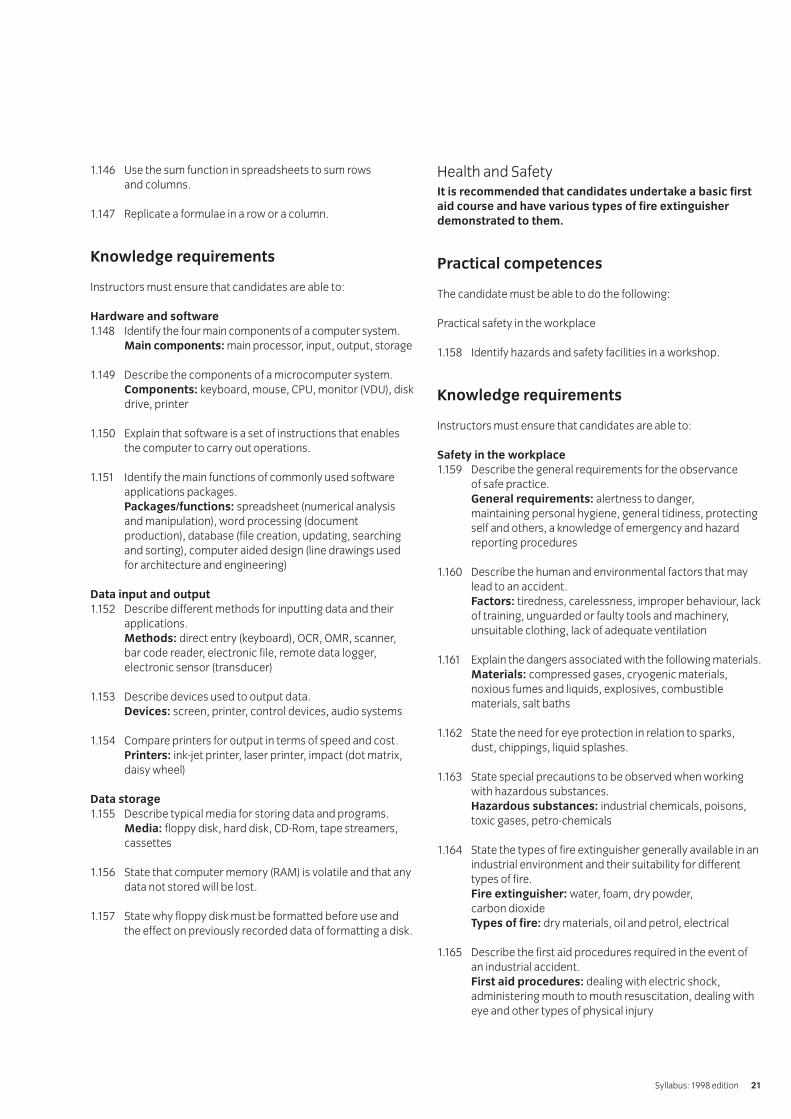
1.148 Identify the four main components of a computer system.Main components: main processor, input, output, storage
1.149 Describe the components of a microcomputer system.Components: keyboard, mouse, CPU, monitor (VDU), diskdrive, printer
1.150 Explain that software is a set of instructions that enablesthe computer to carry out operations.
1.151 Identify the main functions of commonly used softwareapplications packages.Packages/functions: spreadsheet (numerical analysisand manipulation), word processing (documentproduction), database (file creation, updating, searchingand sorting), computer aided design (line drawings usedfor architecture and engineering)
Data input and output
1.152 Describe different methods for inputting data and theirapplications.Methods: direct entry (keyboard), OCR, OMR, scanner,bar code reader, electronic file, remote data logger,electronic sensor (transducer)
1.153 Describe devices used to output data.Devices: screen, printer, control devices, audio systems
1.154 Compare printers for output in terms of speed and cost.Printers: ink-jet printer, laser printer, impact (dot matrix,daisy wheel)
Data storage
1.155 Describe typical media for storing data and programs.Media: floppy disk, hard disk, CD-Rom, tape streamers,cassettes
1.156 State that computer memory (RAM) is volatile and that anydata not stored will be lost.
1.157 State why floppy disk must be formatted before use andthe effect on previously recorded data of formatting a disk.
Health and SafetyIt is recommended that candidates undertake a basic first
aid course and have various types of fire extinguisher
demonstrated to them.
Practical competences
The candidate must be able to do the following:
Practical safety in the workplace
1.158 Identify hazards and safety facilities in a workshop.
Knowledge requirements
Instructors must ensure that candidates are able to:
Safety in the workplace
1.159 Describe the general requirements for the observance of safe practice.General requirements: alertness to danger, maintaining personal hygiene, general tidiness, protectingself and others, a knowledge of emergency and hazardreporting procedures
1.160 Describe the human and environmental factors that maylead to an accident.Factors: tiredness, carelessness, improper behaviour, lackof training, unguarded or faulty tools and machinery,unsuitable clothing, lack of adequate ventilation
1.161 Explain the dangers associated with the following materials.Materials: compressed gases, cryogenic materials,noxious fumes and liquids, explosives, combustiblematerials, salt baths
1.162 State the need for eye protection in relation to sparks,dust, chippings, liquid splashes.
1.163 State special precautions to be observed when workingwith hazardous substances.Hazardous substances: industrial chemicals, poisons,toxic gases, petro-chemicals
1.164 State the types of fire extinguisher generally available in anindustrial environment and their suitability for differenttypes of fire.Fire extinguisher: water, foam, dry powder, carbon dioxideTypes of fire: dry materials, oil and petrol, electrical
1.165 Describe the first aid procedures required in the event ofan industrial accident.First aid procedures: dealing with electric shock,administering mouth to mouth resuscitation, dealing witheye and other types of physical injury
Syllabus: 1998 edition 21

1.166 Describe the sources of electrical danger and the methodsof protection.Methods of protection: insulation, earthing, circuitbreakers, fuses, residual current devices (RCD)
1.167 State the essential procedures for the safe handling andstorage of materials.
1.168 State the correct procedures for lifting bulky or heavyloads including manual lifting and the safe use of liftingequipment.
IVQ in Engineering 256522
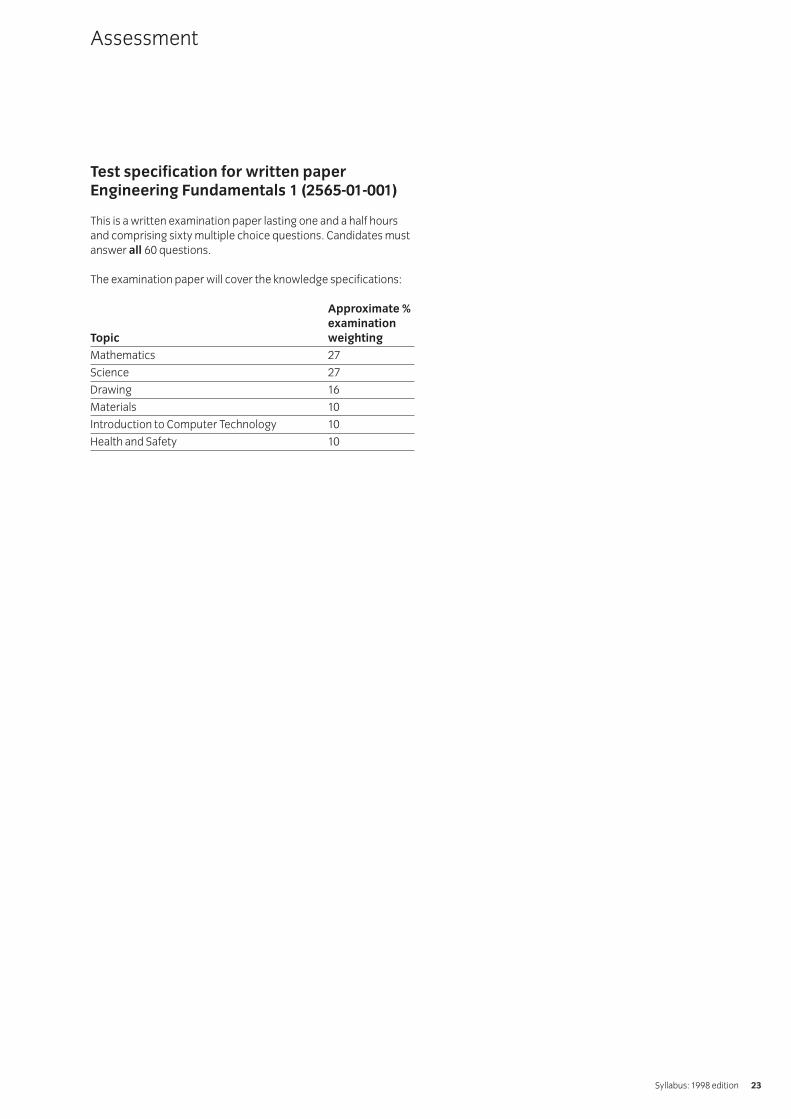
Test specification for written paperEngineering Fundamentals 1 (2565-01-001)
This is a written examination paper lasting one and a half hoursand comprising sixty multiple choice questions. Candidates mustanswer all 60 questions.
The examination paper will cover the knowledge specifications:
Approximate %
examination
Topic weighting
Mathematics 27
Science 27
Drawing 16
Materials 10
Introduction to Computer Technology 10
Health and Safety 10
Assessment
Syllabus: 1998 edition 23
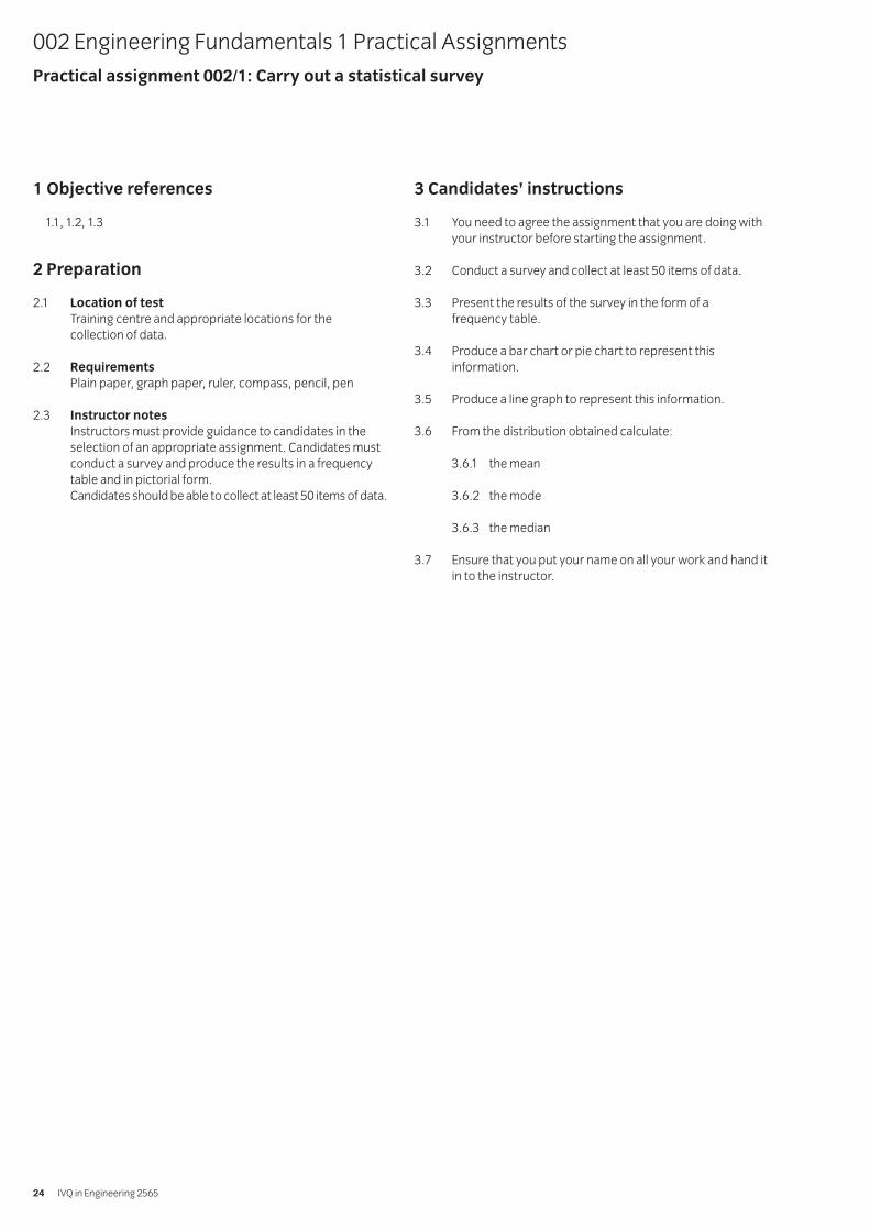
1 Objective references
1.1, 1.2, 1.3
2 Preparation
2.1 Location of test
Training centre and appropriate locations for the collection of data.
2.2 Requirements
Plain paper, graph paper, ruler, compass, pencil, pen
2.3 Instructor notes
Instructors must provide guidance to candidates in theselection of an appropriate assignment. Candidates mustconduct a survey and produce the results in a frequencytable and in pictorial form.Candidates should be able to collect at least 50 items of data.
3 Candidates’ instructions
3.1 You need to agree the assignment that you are doing withyour instructor before starting the assignment.
3.2 Conduct a survey and collect at least 50 items of data.
3.3 Present the results of the survey in the form of a frequency table.
3.4 Produce a bar chart or pie chart to represent thisinformation.
3.5 Produce a line graph to represent this information.
3.6 From the distribution obtained calculate:
3.6.1 the mean
3.6.2 the mode
3.6.3 the median
3.7 Ensure that you put your name on all your work and hand itin to the instructor.
002 Engineering Fundamentals 1 Practical AssignmentsPractical assignment 002/1: Carry out a statistical survey
IVQ in Engineering 256524
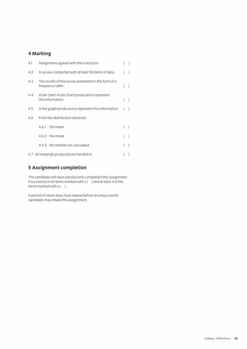
4 Marking
4.1 Assignment agreed with the instructor. [ ]
4.2 A survey conducted with at least 50 items of data. [ ]
4.3 The results of the survey presented in the form of afrequency table. [ ]
4.4 A bar chart or pie chart produced to represent this information. ( )
4.5 A line graph produced to represent this information. ( )
4.6 From the distribution obtained
4.6.1 the mean ( )
4.6.2 the mode ( )
4.6.3 the median are calculated ( )
4.7 All materials produced are handed in. [ ]
5 Assignment completion
The candidate will have satisfactorily completed this assignmentif successful in all items marked with a [ ] and at least 4 of theitems marked with a ( ).
A period of seven days must elapse before an unsuccessfulcandidate may retake this assignment.
Syllabus: 1998 edition 25

1 Objective references
1.49, 1.50
2 Preparation
2.1 Location of test
The training centre or other venue where supervision andappropriate working conditions will be provided.
2.2 Requirements
Ticker-timer with 12V ac supply
Ticker-timer tape
‘Model (toy) car’ whose velocity is to be measured (couldbe hand-made)
Wooden plank to act as runway
1m ruler to measure distances
2.3 Instructor notes
Candidates may undertake assignments in pairs, provided results analysis is undertaken independently byeach candidate.
In this experiment a ticker-timer is used to investigatemotion. The timer prints dots on a paper tape at regularintervals (eg one dot every 0.02 s). The tape passesthrough the ticker-timer and is attached to the model carwhich is placed on top of a slope. The timer is started andthe car is allowed to run down the slope.
The candidate should take the tape chart and measure thedistance travelled at regular intervals, eg 0.2s. A plot of‘Displacement’ against ‘Time’ can then be used tocalculate Velocity at any instance.
It may be useful for the instructor to undertake a dummyrun demonstration of the procedures before allowing thecandidates to proceed.
The writing up of this assignment may be done outside the21⁄2 hour practical session.
Alternative apparatus/equipment for this experiment
may be used, eg air track, Fletcher’s trolley.
002 Engineering Fundamentals 1 Practical AssignmentsPractical assignment 002/2: Construct distance/time graphs from measured data
IVQ in Engineering 256526
3 Candidates’ instructions
3.1 The time allowed for this assignment is 21⁄2 hours. You areadvised to read all the instructions before commencingwork. If you do not understand all the instructions thenplease ask you instructor.
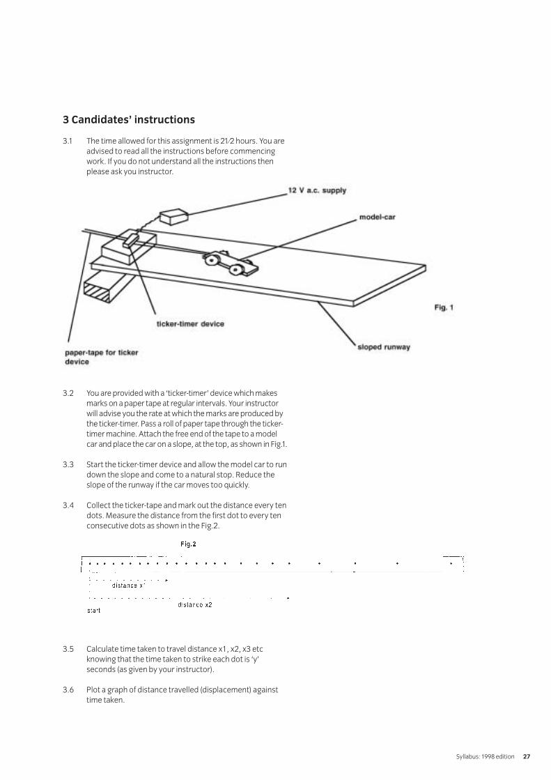
3.2 You are provided with a ‘ticker-timer’ device which makesmarks on a paper tape at regular intervals. Your instructorwill advise you the rate at which the marks are produced bythe ticker-timer. Pass a roll of paper tape through the ticker-timer machine. Attach the free end of the tape to a modelcar and place the car on a slope, at the top, as shown in Fig.1.
3.3 Start the ticker-timer device and allow the model car to rundown the slope and come to a natural stop. Reduce theslope of the runway if the car moves too quickly.
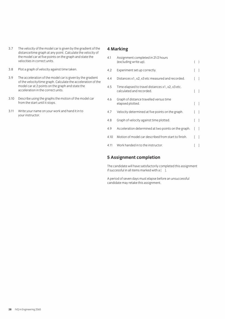
3.4 Collect the ticker-tape and mark out the distance every tendots. Measure the distance from the first dot to every tenconsecutive dots as shown in the Fig.2.
3.5 Calculate time taken to travel distance x1, x2, x3 etcknowing that the time taken to strike each dot is ‘y’seconds (as given by your instructor).
3.6 Plot a graph of distance travelled (displacement) againsttime taken.
Syllabus: 1998 edition 27
3.7 The velocity of the model car is given by the gradient of thedistance/time graph at any point. Calculate the velocity ofthe model car at five points on the graph and state thevelocities in correct units.
3.8 Plot a graph of velocity against time taken.
3.9 The acceleration of the model car is given by the gradientof the velocity/time graph. Calculate the acceleration of themodel car at 2 points on the graph and state theacceleration in the correct units.
3.10 Describe using the graphs the motion of the model carfrom the start until it stops.
3.11 Write your name on your work and hand it in to your instructor.
4 Marking
4.1 Assignment completed in 21⁄2 hours (excluding write up). ( )
4.2 Experiment set up correctly. [ ]
4.4 Distances x1, x2, x3 etc measured and recorded. [ ]
4.5 Time elapsed to travel distances x1, x2, x3 etc. calculated and recorded. [ ]
4.6 Graph of distance travelled versus time elapsed plotted. [ ]
4.7 Velocity determined at five points on the graph. [ ]
4.8 Graph of velocity against time plotted. [ ]
4.9 Acceleration determined at two points on the graph. [ ]
4.10 Motion of model car described from start to finish. [ ]
4.11 Work handed in to the instructor. [ ]
5 Assignment completion
The candidate will have satisfactorily completed this assignmentif successful in all items marked with a [ ].
A period of seven days must elapse before an unsuccessfulcandidate may retake this assignment.
IVQ in Engineering 256528
1 Objective references
1.52
2 Preparation
2.1 Location of test
The training centre or other venue where supervision andappropriate working conditions will be provided.
2.2 Requirements
Thermometer (°C)One 500 ml beakerOne 1 litre beakerPolystyrene insulation (beads or broken pieces of styrene block)Liquid whose specific heat capacity is to be measuredRheostat and electrical connectionsVoltmeterAmmeterStop clockElectrical immersion heaterStirrerInsulating lid for 500 ml beaker with holes forthermometer, stirrer, andconnections for electrical heaterPower supplyWeighing scales in grams
2.3 Instructor notes
Candidates should be familiar with basic electrical circuitsinvolving power sources, voltmeter, ammeter and rheostatand know the function of each of these devices. Candidatesshould also be familiar with the equation: Electrical Energy(Q) supplied over a period of time = IVt, (where I is thecurrent in amps, V is the voltage and t is time)
Health and safety should be carefully considered when
using live electrical circuits and liquids such as water.
The instructor is advised to carry out a dummy rundemonstration for candidates prior to letting them use the equipment.
The write up for the experiment can be carried out outsideof the 2 hour practical time.
002 Engineering Fundamentals 1 Practical AssignmentsPractical assignment 002/3: Measuring the specific heat capacity of a liquid
Syllabus: 1998 edition 29
3 Candidates’ instructions
3.1 The time allowed for this assignment is 2 hours. You areadvised to read all the instructions before commencingwork. If you do not understand all the instructions thenplease ask your instructor.
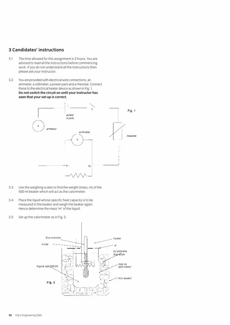
3.2 You are provided with electrical wire connections, anammeter, a voltmeter, a power pack and a rheostat. Connectthese to the electrical heater device as shown in Fig. 1.Do not switch the circuit on until your instructor has
seen that your set-up is correct.
3.3 Use the weighing scales to find the weight (mass, m) of the500 ml beaker which will act as the calorimeter.
3.4 Place the liquid whose specific heat capacity is to bemeasured in the beaker and weigh the beaker again.Hence determine the mass ‘m’ of the liquid.
3.5 Set up the calorimeter as in Fig. 2.
IVQ in Engineering 256530

3.6 Record the initial temperature of the liquid: θ1
3.7 Switch the current through the heater and start the stop-clock.
3.8 Heat the liquid for say ten minutes (to obtain a measurable rise in temperature). Read the voltage and current supplied.
3.9 Stop the heater and stop clock.
3.10 Measure the final temperature: θ2
3.11 Calculate the heat energy supplied to the liquid (in Joules),using the formulae:
Energy supplied = IVt where I is current in amperesV is voltage in voltst is time in seconds
3.12 Assume that all the heat supplied is transferred to the liquidand none is lost (because we insulated the glass calorimeter).Also assume that the specific heat capacity of the glasscalorimeter is negligible and heat transferred to the glass is minimal.
Hence,
Heat supplied by heater = heat absorbed by liquid
Heat absorbed by liquid = mc (θ2 – θ1)
Where m = mass of liquid in kilograms
c = specific heat capacity of liquid in J/kg K
Hence, knowing the value of ‘m’ and ‘(θ2 – θ1)’, calculatethe specific heat capacity.
3.13 Write up this assignment, ensure your name is on yourwork and hand it in to your instructor.
Syllabus: 1998 edition 31

4 Marking
4.1 Assignment completed in 2 hours (excluding write up). ( )
4.2 Electrical circuit set up correctly. [ ]
4.3/4.4 Mass of liquid determined in kilograms. [ ]
4.5 Calorimeter set up correctly. [ ]
4.6 Initial temperature of liquid measured. [ ]
4.10 Final temperature of liquid measured. [ ]
4.11 Voltage and current supplied is measured and heat energy supplied to liquid is calculated. [ ]
4.12 Specific heat capacity of liquid is correctly calculated using correct units. [ ]
4.13 Work handed in to the instructor. [ ]
5 Assignment completion
The candidate will have satisfactorily completed this assignmentif successful in all the items marked with a [ ].
A period of seven days must elapse before an unsuccessfulcandidate may retake this assignment. An alternative liquidshould be used for analysis.
IVQ in Engineering 256532
1 Objective references
1.51
2 Preparation
2.1 Location of test
The training centre or other venue where supervision andappropriate working conditions will be provided.
2.2 Requirements
Power pack or battery of several cells
Ammeter with ranges of 0-10A and 0-1A
Voltmeter with a range of 0-5 V
2x Variable resistors (rheostats): one with 20 ohm maximumresistance and another with 10 ohm maximum resistance
Electrical circuit connectors
Filament lamp (tungsten) 2.5 V
2.3 Instructor notes
Candidates may undertake assignments in pairs, provided results analysis is undertaken independently byeach candidate.
Candidates must be familiar with Ohm’s law, electricalcircuits and the functions of resistors, ammeters andvariable resistors.
Health and safety issues must be explained to candidatesin the context of use of electric currents. It may be usefulfor the instructor to undertake a dummy rundemonstration of the procedures before allowing thecandidates to proceed. It is particularly useful to check thatthe filament lamp will display non-ohmic relationship atreasonable voltage values.
The writing up of this assignment may be done outside thetwo hour practical session.
002 Engineering Fundamentals 1 Practical AssignmentsPractical assignment 002/4: Demonstrate the effect of heat on the resistance of a conductor
Syllabus: 1998 edition 33
3 Candidates’ instructions
3.1 The time allowed for this assignment is 2 hours. You areadvised to read all the instructions before commencingwork. If you do not understand all the instructions thenplease ask you instructor.
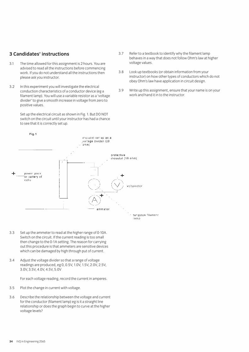
3.2 In this experiment you will investigate the electricalconduction characteristics of a conductor device (eg afilament lamp). You will use a variable resistor as a ‘voltagedivider’ to give a smooth increase in voltage from zero topositive values.
Set up the electrical circuit as shown in Fig. 1. But DO NOTswitch on the circuit until your instructor has had a chanceto see that it is correctly set up.
3.3 Set up the ammeter to read at the higher range of 0-10A.Switch on the circuit. If the current reading is too smallthen change to the 0-1A setting. The reason for carryingout this procedure is that ammeters are sensitive deviceswhich can be damaged by high through put of current.
3.4 Adjust the voltage divider so that a range of voltagereadings are produced, eg 0, 0.5V, 1.0V, 1.5V, 2.0V, 2.5V,3.0V, 3.5V, 4.0V, 4.5V, 5.0V
For each voltage reading, record the current in amperes.
3.5 Plot the change in current with voltage.
3.6 Describe the relationship between the voltage and currentfor the conductor (filament lamp) eg is it a straight linerelationship or does the graph begin to curve at the highervoltage levels?
3.7 Refer to a textbook to identify why the filament lampbehaves in a way that does not follow Ohm’s law at highervoltage values.
3.8 Look up textbooks (or obtain information from yourinstructor) on how other types of conductors which do notobey Ohm’s law have application in circuit design.
3.9 Write up this assignment, ensure that your name is on yourwork and hand it in to the instructor.
IVQ in Engineering 256534

4 Marking
4.1 Assignment completed in 2 hours (excluding write up). ( )
4.2 Electrical circuit set up as advised. [ ]
4.3 A range of voltage and current readings taken. [ ]
4.4 Graph of current against voltage plotted. [ ]
4.5 Relationship between current and voltage for theconductor correctly described. [ ]
4.6 Relationship correctly identified as non-ohmic and due to Increase in resistance due to heating effects. [ ]
4.7 Application of non-ohmic properties in other conductordevices in use in electrical circuits appreciated in a verygeneral way. ( )
4.8 Work handed in to the instructor. [ ]
5 Assignment completion
The candidate will have satisfactorily completed this assignmentif successful in all items marked with a [ ] and at least 1 of theitems marked with a ( ).
A period of seven days must elapse before an unsuccessfulcandidate may retake this assignment.
Syllabus: 1998 edition 35
1 Objective references
1.95, 1.96
2 Preparation
2.1 Location of test
The training centre or other venue where supervision andappropriate working conditions will be provided.
2.2 Requirements
Drafting machine or drawing board and Tee square,drawing instruments and A3 drawing paper.
Copy of section 6
2.3 Instructor notes
Candidates are required to construct two isometricdrawings and two oblique drawings of simple shapeswhich include flat surfaces, angular surfaces, curvedsurfaces and cylindrical shapes. The time allowed for thisassignment is 3 hours.
3 Candidates’ instructions
3.1 In Section 6, figure 1 shows four simple engineeringcomponents. Figure 1a and figure 1b are drawn inisometric projection and figure 1c and figure 1d are drawnin oblique projection. You must redraw the isometriccomponents in oblique projection and the obliquecomponents must be redrawn in isometric projection.
You have 3 hours to complete this assignment.
3.2 Produce a drawing sheet with appropriate layout and title.
3.3 Draw full size the two isometric projections figures 1a and1b in oblique projection:
3.3.1 Figure 1a in oblique projection.
3.3.2 Figure 1b in oblique projection.
3.4 Draw full size the two oblique projections figures 1c and 1din isometric projection:
3.4.1 Figure 1c in isometric projection.
3.4.2 Figure 1d in isometric projection.
3.5 Ensure the drawing:
3.1.1 represents the component correctly.
3.1.2 represents the drawing accurately.
3.1.3 interprets the views correctly.
3.1.4 meets BS308 or ISO standards.
3.6 Ensure your name is on your work and hand in to the instructor.
002 Engineering Fundamentals 1 Practical AssignmentsPractical assignment 002/5: Interpret isometric and oblique views
IVQ in Engineering 256536
4 Marking
4.1 Assignment completed in 3 hours. ( )
4.2 A drawing sheet with appropriate layout and title produced. ( )
4.3 The two isometric projections figures 1a and 1b in obliqueprojection drawn full size:
4.3.1 Figure 1a in oblique projection. ( )
4.3.2 Figure 1b in oblique projection. [ ]
4.4 The two oblique projections figures 1c and 1d in isometricprojection drawn full size:
4.4.1 Figure 1c in isometric projection. ( )
4.4.2 Figure 1d in isometric projection. [ ]
4.5 The drawings produced:
4.5.1 represents the component correctly. [ ]
4.5.2 represents the drawing accurately. [ ]
4.5.3 interprets the views correctly. [ ]
4.5.4 meets BS308 or ISO standards. ( )
4.6 Work handed in to the instructor. [ ]
5 Assignment completion
The candidate will have satisfactorily completed this assignmentif successful in all items marked with a [ ] and at least three ofthe items marked with a ( ) for each drawing.
Candidates may retake this assignment or use alternative dataproduced by the instructor.
Syllabus: 1998 edition 37
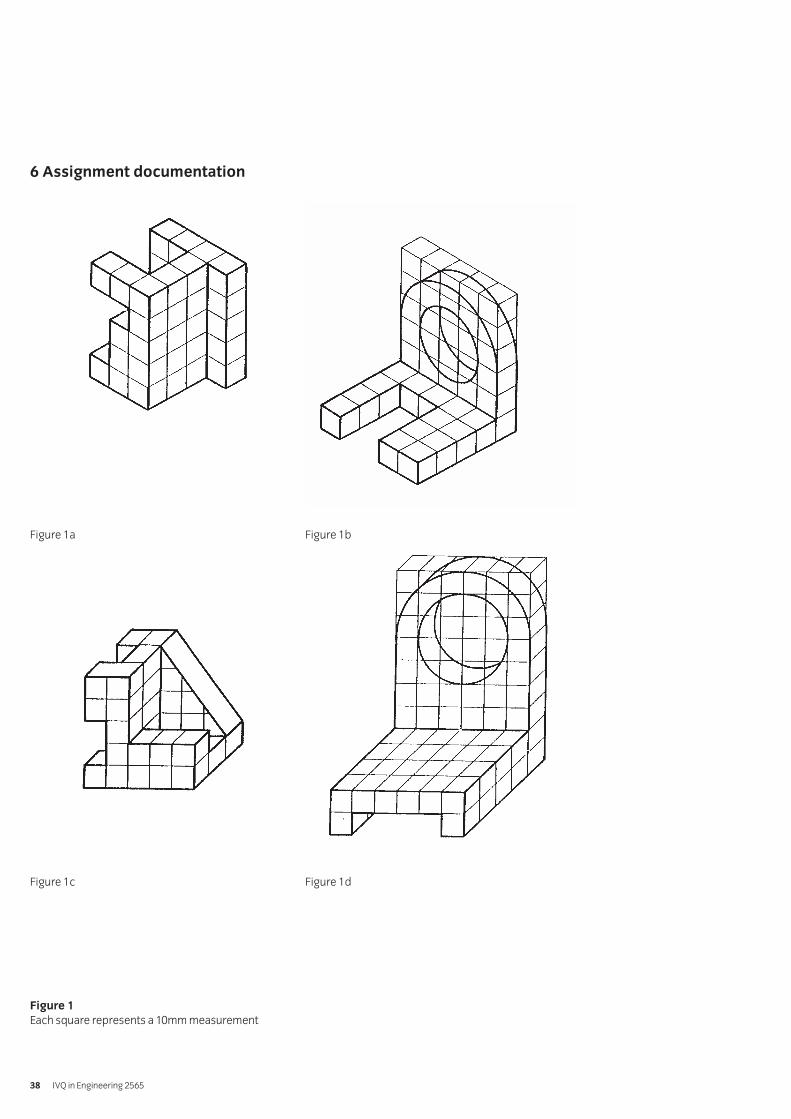
6 Assignment documentation
Figure 1a Figure 1b
Figure 1c Figure 1d
Figure 1
Each square represents a 10mm measurement
IVQ in Engineering 256538
1 Objective references
1.99
2 Preparation
2.1 Location of test
The training centre or other venue where supervision andappropriate working conditions will be provided.
2.2 Requirements
Drafting machine or drawing board and Tee square,drawing instruments and A3 drawing paper.
Access to BS308 or equivalent ISO standards.
Copy of section 6.
2.3 Instructor notes
Candidates are required to construct a standard view of adetail drawing in 1st or 3rd angle projection of the ‘V’ blockshown in section 6. The detail drawing must be fullydimensioned and must include a title block. Time allowedfor the assignment is 2 hours.
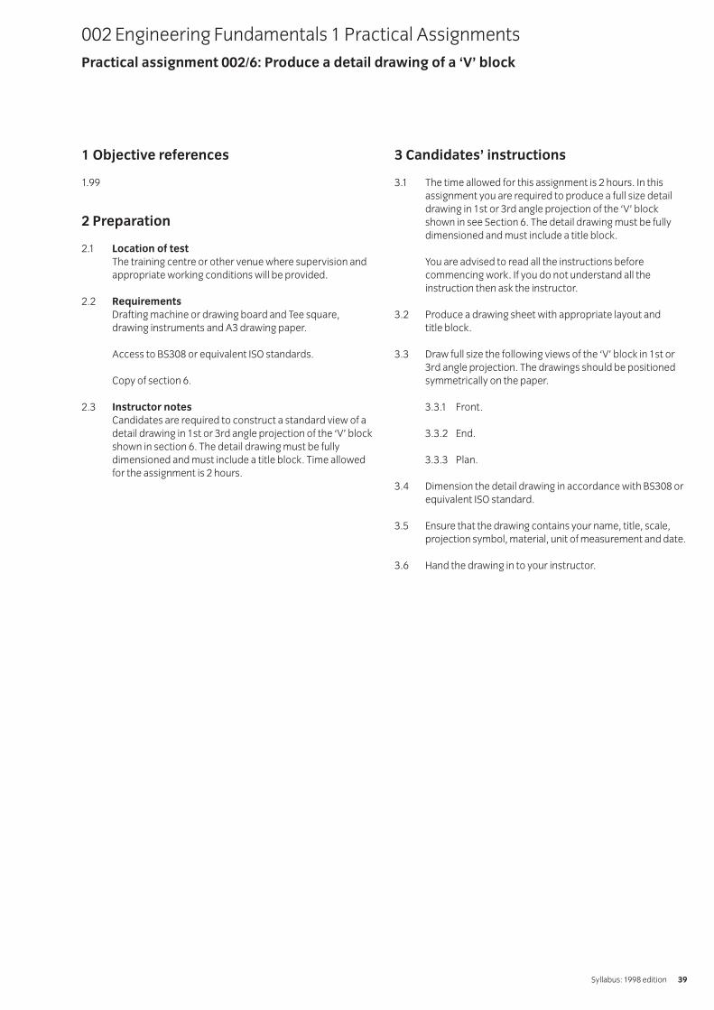
3 Candidates’ instructions
3.1 The time allowed for this assignment is 2 hours. In thisassignment you are required to produce a full size detaildrawing in 1st or 3rd angle projection of the ‘V’ blockshown in see Section 6. The detail drawing must be fullydimensioned and must include a title block.
You are advised to read all the instructions beforecommencing work. If you do not understand all theinstruction then ask the instructor.
3.2 Produce a drawing sheet with appropriate layout and title block.
3.3 Draw full size the following views of the ‘V’ block in 1st or3rd angle projection. The drawings should be positionedsymmetrically on the paper.
3.3.1 Front.
3.3.2 End.
3.3.3 Plan.
3.4 Dimension the detail drawing in accordance with BS308 orequivalent ISO standard.
3.5 Ensure that the drawing contains your name, title, scale,projection symbol, material, unit of measurement and date.
3.6 Hand the drawing in to your instructor.
002 Engineering Fundamentals 1 Practical AssignmentsPractical assignment 002/6: Produce a detail drawing of a ‘V’ block
Syllabus: 1998 edition 39

4 Marking
4.1 Assignment completed in 2 hours. ( )
4.2 A drawing sheet with appropriate layout and title block produced. ( )
4.3 A full size detail drawing in 1st or 3rd angle projectionshowing the following views:
4.3.1 Front [ ]
4.3.2 End [ ]
4.3.3 Plan ( )
4.4 The detail drawing dimensioned in accordance with BS308 or equivalent ISO standard. [ ]
4.5 Your name, title, scale, projection symbol, material unit of measurement and date written on the drawing. [ ]
4.6 Drawing handed in to your instructor. [ ]
5 Assignment completion
The candidate will have satisfactorily completed this assignmentif successful in all items marked with a [ ] and 1 item marked with a ( ).
A period of seven days must elapse before an unsuccessfulcandidate may retake this assignment.
IVQ in Engineering 256540
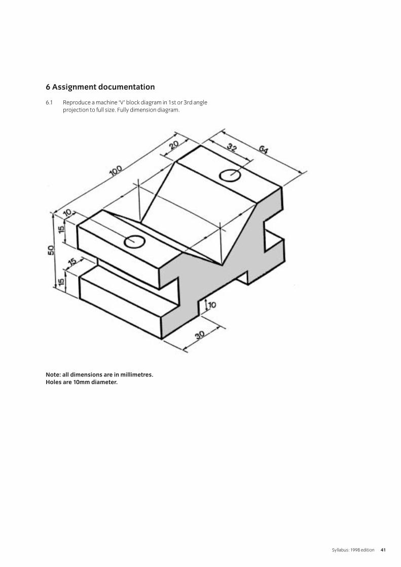
6 Assignment documentation
6.1 Reproduce a machine ‘V’ block diagram in 1st or 3rd angleprojection to full size. Fully dimension diagram.
Note: all dimensions are in millimetres.
Holes are 10mm diameter.
Syllabus: 1998 edition 41
1 Objective references
1.99
2 Preparation
2.1 Location of test
The training centre or other venue where supervision andappropriate working conditions will be provided.
2.2 Requirements
Drafting machine or drawing board and Tee square,drawing instruments and A3 drawing paper.
Access to BS308 or equivalent ISO standards.
Copy of section 6.
2.3 Instructor notes
Candidates are required to construct a standard view of adetail drawing in 1st or 3rd angle projection of the HeatSink shown in section 6. The detail drawing must be fullydimensioned and must include a title block. Time allowedfor the assignment is 2 hours.
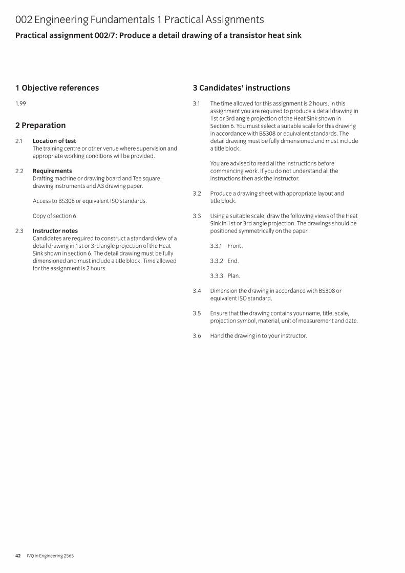
3 Candidates’ instructions
3.1 The time allowed for this assignment is 2 hours. In thisassignment you are required to produce a detail drawing in1st or 3rd angle projection of the Heat Sink shown inSection 6. You must select a suitable scale for this drawingin accordance with BS308 or equivalent standards. Thedetail drawing must be fully dimensioned and must includea title block.
You are advised to read all the instructions beforecommencing work. If you do not understand all theinstructions then ask the instructor.
3.2 Produce a drawing sheet with appropriate layout and title block.
3.3 Using a suitable scale, draw the following views of the HeatSink in 1st or 3rd angle projection. The drawings should bepositioned symmetrically on the paper.
3.3.1 Front.
3.3.2 End.
3.3.3 Plan.
3.4 Dimension the drawing in accordance with BS308 orequivalent ISO standard.
3.5 Ensure that the drawing contains your name, title, scale,projection symbol, material, unit of measurement and date.
3.6 Hand the drawing in to your instructor.
002 Engineering Fundamentals 1 Practical AssignmentsPractical assignment 002/7: Produce a detail drawing of a transistor heat sink
IVQ in Engineering 256542

4 Marking
4.1 Assignment completed in 2 hours. ( )
4.2 A drawing sheet with appropriate layout and title block produced. ( )
4.3 A Heat Sink drawn to a suitable scale in 1st or 3rd angle projection:
4.3.1 Front [ ]
4.3.2 End [ ]
4.3.3 Plan. ( )
4.4 The drawing dimensioned in accordance with BS308 or equivalent ISO standard. [ ]
4.5 Your name, title, scale, projection symbol, material, unit of measurement and date on the drawing. [ ]
4.6 Drawing handed in to your instructor. [ ]
5 Assignment completion
The candidate will have satisfactorily completed this assignmentif successful in all items marked with a [ ] and 1 other markedwith a ( ).
A period of seven days must elapse before an unsuccessfulcandidate may retake this assignment.
Syllabus: 1998 edition 43
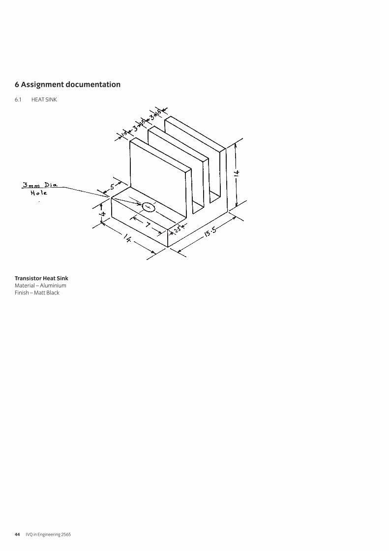
6 Assignment documentation
6.1 HEAT SINK
Transistor Heat Sink
Material – AluminiumFinish – Matt Black
IVQ in Engineering 256544
1 Objective references
1.100
2 Preparation
2.1 Location of test
The training centre or other venue where supervision andappropriate working conditions will be provided.
2.2 Requirements
Drafting machine or drawing board and Tee square,drawing instruments and A3 drawing paper.
Access to BS308 or equivalent standards.
Copy of section 6.
2.3 Instructor notes
Candidates are required to draw three views of anassembly drawing in first or third angle projection shown inSection 6, figure 1. The drawing must be drawn to BS308 orequivalent ISO standard and must include an appropriatetitle block and a parts list.
The time allowed for this assessment is 6 hours.
3 Candidates’ instructions
3.1 The time allowed for this assignment is 6 hours. You areadvised to read all the instructions before starting work.The dimensions shown in section 6 are in mm.
In section 6, figure 1 shows components of a pulley unit infirst angle projection. The bush is located on the top face ofthe bracket with the large diameter of the bush adjacent tothe face. A hexagonal nut and washer (not shown in figure 1) is used to hold the spindle in the bracket. The nutand washer must be drawn. Hidden details or dimensionsare not required.
3.2 Produce a drawing sheet with appropriate layout and title.
3.3 Draw full size in either first or third angle projection thefollowing views of the pulley and support bracket assembly:
3.3.1 A sectional front view on plane AA.
3.3.2 An end view.
3.3.3 A plan view.
3.4 Balloon (item) reference the assembly.
3.5 Draw up a parts list to include a suitable material for each component.
3.6 Ensure the drawing takes the following aspects into account:
3.6.1 The correct assembly.
3.6.2 The accuracy of the drawing.
3.6.3 The correct projection interpretation of the two views.
3.6.4 The quality of the drawing.
3.7 Ensure your name is on your work and hand it in to your instructor.
002 Engineering Fundamentals 1 Practical AssignmentsPractical assignment 002/8: Assembly drawing of a pulley and support bracket
Syllabus: 1998 edition 45

4 Marking
4.1 Assignment completed in 6 hours. ( )
4.2 Drawing sheet with appropriate layout and title produced. ( )
4.3 Either first or third angle projection of the following views of the assembly drawn in full size.
4.3.1 A sectional front view on plane AA [ ]
4.3.2 An end view [ ]
4.3.3 A plan view ( )
4.4 The assembly balloon referenced. ( )
4.5 A parts list to include a suitable material for eachcomponent drawn up. ( )
4.6 The drawing produced taking the following aspects intoaccount:
4.6.1 The correct assembly. [ ]
4.6.2 The accuracy of the drawing. [ ]
4.6.3 The correct projection interpretation of the two views. [ ]
4.6.4 The quality of the drawing. [ ]
4.7 Work handed in to the instructor. [ ]
5 Assignment completion
The candidate will have satisfactorily completed this assignmentif successful in all items marked with a [ ] and at least three ofthe items marked with a ( ).
Candidates may retake this assignment or an alternativeassignment produced by the instructor.
IVQ in Engineering 256546
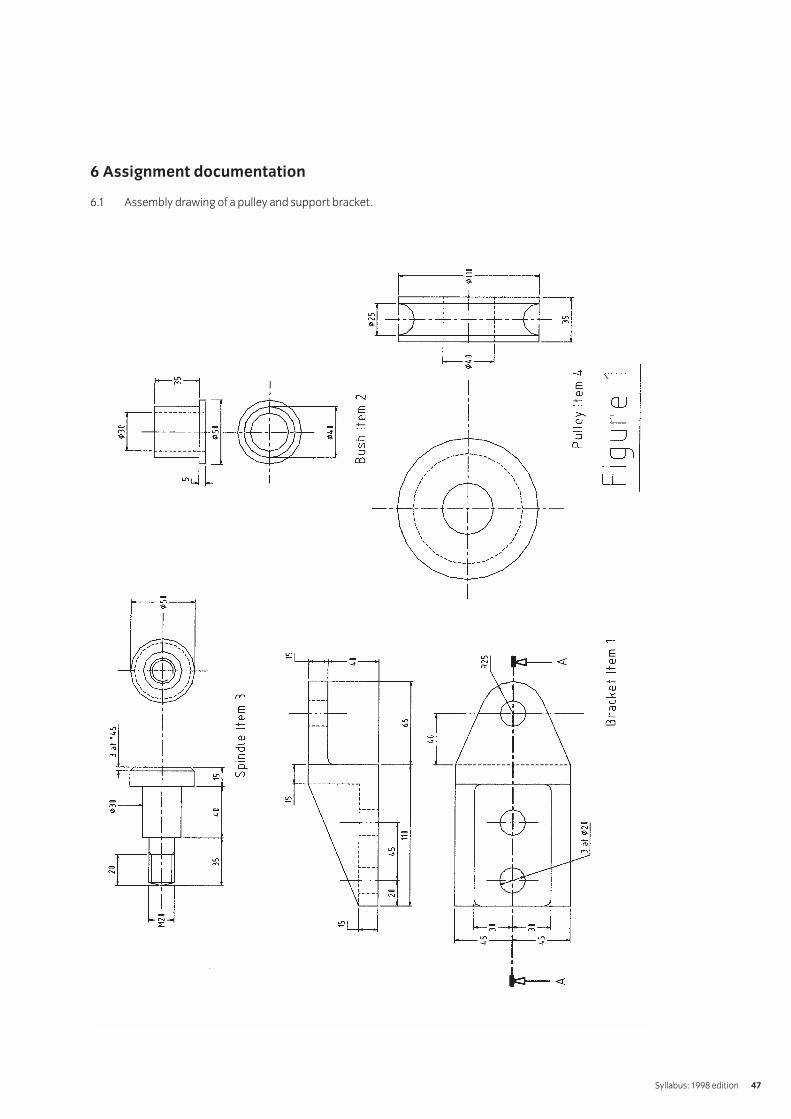
6 Assignment documentation
6.1 Assembly drawing of a pulley and support bracket.
Syllabus: 1998 edition 47
1 Objective references
1.103
2 Preparation
2.1 Location of test
The training centre or other venue where supervision andappropriate working conditions will be provided.
2.2 Requirements
Copy of section 6.
2.3 Instructor notes
Using the logic controlled power switch chart in section 6,candidates are required to identify the component typeand briefly describe its function. Time allowed for theassignment is 2 hours.
3 Candidates’ instructions
3.1 The time allowed for this assignment is 2 hours. In thisassignment you are required to use section 6.1 – the logiccontrolled power switch chart and identify the componenttype and briefly describe its function. You should enteryour answers on the sheet in section 6.2. Time allowed forthe assignment is 2 hours.
You are advised to read all the instructions beforecommencing work. If you do not understand all theinstruction then ask the instructor.
3.2 Identify the component types.
3.3 Describe the function of each component.
3.4 Write your name on the answer sheet and hand it in to yourinstructor.
002 Engineering Fundamentals 1 Practical AssignmentsPractical assignment 002/9: Logic controlled power switch
IVQ in Engineering 256548
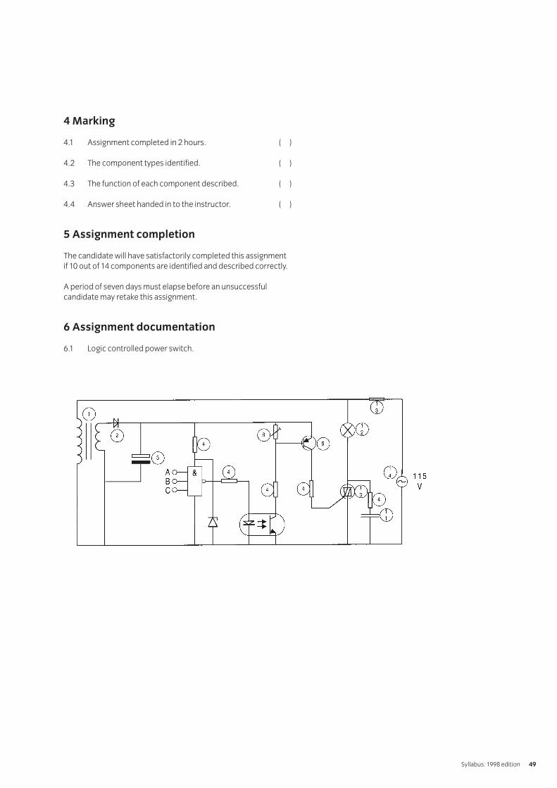
4 Marking
4.1 Assignment completed in 2 hours. ( )
4.2 The component types identified. ( )
4.3 The function of each component described. ( )
4.4 Answer sheet handed in to the instructor. ( )
5 Assignment completion
The candidate will have satisfactorily completed this assignmentif 10 out of 14 components are identified and described correctly.
A period of seven days must elapse before an unsuccessfulcandidate may retake this assignment.
6 Assignment documentation
6.1 Logic controlled power switch.
Syllabus: 1998 edition 49

6.2. Answer sheet
Name
IVQ in Engineering 256550
Component ref Component type Function
1
2
3
4
5
6
7
8
9
10
11
12
13
14
1 Objective references
1.120
2 Preparation
2.1 Location of test
The training centre or other venue where supervision andappropriate working conditions will be provided.
2.2 Requirements
Copy of section 6 – Database of Materials
An every day simple electronic or mechanical productwhich consists of several different materials (eg a hand-held battery torch or an electrical plug).
2.3 Instructor notes
Instructors may prepare their own database of materialsfor use in this assignment. Time allowed for thisassignment is 1 hour.
3 Candidates’ instructions
3.1 The time allowed for this assignment is 1 hour. You areadvised to read all the instructions before commencingwork. If you do not understand all the instructions thenplease ask you instructor.
3.2 You are provided with a database of materials and an itemwhich is of everyday use, eg a battery torch.
Analyse the item to identify the different types of materialswhich are used in the construction of the product. Yourinstructor will advise you on whether you can dismantlethe item to carry out your analysis.
Analyse the materials used in the item and for eachmaterial consider the following:
i Does the material need to be light or heavy?ii Does the material need to be strong?iii Is the material used for its flexibility or
stiffness properties?iv Is the material used for its moulding properties?v Is the material used for its electrical conduction
properties?vi Is the material used for its thermal (heat)
conduction ability?vii Is the material used for its insulation properties?viii Consider the cost of the material and decide if
alternative cheaper material could be used in its place.
You may find it useful to create a table to record your findings.
3.3 Write up this assignment, ensure your name is on yourwork and hand it in to your instructor.
002 Engineering Fundamentals 1 Practical AssignmentsPractical assignment 002/10: Selecting materials for product applications
Syllabus: 1998 edition 51

4 Marking
4.1 Assignment completed in 1 hour (excluding write up). ( )
4.2 i Light/heavy qualities of materials considered ( )ii Strength quality of material considered ( )iii Flexibility/stiffness properties of materials
considered ( )iv Moulding properties of materials considered ( )v Electrical conduction properties of materials
considered ( )vi Thermal conduction properties of materials
considered ( )vii Insulation properties of materials considered ( )viii Cost factors and alternative materials considered. ( )
4.3 Assignment written up and handed in to the instructor. [ ]
5 Assignment completion
The candidate will have satisfactorily completed this assignmentif successful in the item marked with a [ ] and at least 7 of theitems marked with a ( ).
A period of seven days must elapse before an unsuccessfulcandidate may retake this assignment. An alternative productshould be used for analysis.
IVQ in Engineering 256552
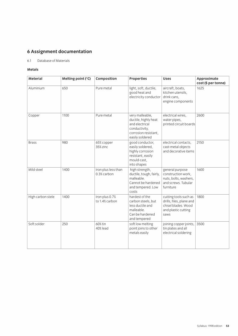
6 Assignment documentation
6.1 Database of Materials
Metals
Syllabus: 1998 edition 53
Meterial Melting point (°C) Composition Properties Uses Approximate
cost ($ per tonne)
Aluminium 650 Pure metal light, soft, ductile, aircraft, boats, 1625good heat and kitchen utensils,electricity conductor drink cans,
engine components
Copper 1100 Pure metal very malleable, electrical wires, 2600ductile, highly heat water pipes,and electrical printed circuit boardsconductivity, corrosion resistant, easily soldered
Brass 980 65% copper good conductor, electrical contacts, 215035% zinc easily soldered, cast-metal objects
highly corrosion and decorative itemsresistant, easilymould-cast,into shapes
Mild steel 1400 Iron plus less than high strength, general purpose 16000.3% carbon ductile, tough, fairly, construction work,
malleable. nuts, bolts, washers, Cannot be hardened and screws. Tubular and tempered. Low furniturecosts
High carbon stele 1400 Iron plus 0.7% hardest of the cutting tools such as 1800to 1.4% carbon carbon steels, but drills, files, plane and
less ductile and chisel blades. Wood malleable. and plastic cutting Can be hardened sawsand tempered
Soft solder 250 60% tin soft low melting joining copper joints, 350040% lead point joins to other tin plates and all
metals easily electrical soldering

Plastics
IVQ in Engineering 256554
Name Chemical name Properties Uses Approximate cost
cost ($ per tonne)
Low density low density wide range of colours, good squeezy bottles, toys, TV aerial 500polythene polyethylene insulator, good chemical lead insulation, plastic sacks
resistance, flexible, soft, and sheetsworking temperature up to 60°C
High density High density wide range of colours, stiff and buckets, bowls and other 700polythene polyethylene hard, can be sterilised, fades in household wares, milk crates,
light unless stabilised, easily boxes, barrels, some machine injected and blown (moulding) parts
Rigid PVC rigid wide range of colours, tough at plumbing fittings, pipes and 800polychloroethane room temperature, can be used gutters, curtain rails, roofing and
outdoors, stiff & hard, good for constructional sheetsfabricating
Acrylic polymethyl stiff, hard, clear or opaque, signs for shops, aircraft canopies, 400methacrylate many colours available, very double glazing, baths, furniture,
durable, can be polished easily, caravan windowsgood electrical insulator, ten times more impact resistant than glass, safe when in contact with food, can be bent and formed easily at about 160 °C
Nylon polyamide hard, tough, wear resistant, self bearings, gear wheels, clothing, 500lubricating, high melting point packaging
1 Objective references
1.129, 1.138
2 Preparation
2.1 Location of test
The training centre or other venue where supervisor andappropriate working conditions will be provided.
2.2 Requirements
Computer system providing access to word processing,database and spreadsheet software connected togetherand switched on.
Software user manuals.
Printer with paper loaded.
Formatted floppy disk and disk labels (work may be savedonto candidate’s area of the network).
Copy of section 6.
Pen, pencil.
2.3 Instructor notes
For simplicity, this assignment is written for use with floppydisks to save electronic files for marking. Time allowed forthis assignment is 11⁄2 hours.
3 Candidates’ instructions
3.1 The time allowed for this assignment is 1 hour and 30minutes. In this assignment you are required to create abusiness letter and amend it.
You are advised to read all of the instructions beforecommencing work. Ensure that you understand all theinstructions and follow them precisely. If you are in anydoubt ask the instructor.
Unless otherwise instructed by your instructor, all files areto be saved on the floppy disk provided.
3.2 On your computer system you have word processing,database, graphics and spreadsheet software available.Access the appropriate software for this task.
3.3 You are required to create a new document which shouldbe typed exactly as shown in section 6.1.
3.4 Save the document as LETTER on the floppy disk providedand print a copy.
3.5 You are now going to make the following changes to the letter:
3.5.1 Centre justify the first 5 lines (the address).3.5.2 Centre justify the line containing ‘Order no.
CC145’ and make the text bold.3.5.3 In the first paragraph of the letter, delete
the word ‘old’.3.5.4 In the last paragraph of the letter, insert the
words ‘latest’ before the word ‘model’.3.5.5 Insert 4 more blank lines between ‘Yours
sincerely’ and ‘G Marlow’.3.5.6 Enter your own name in the document next
to ‘copy to’.
3.6 Save the file with the filename LETTER1 on your floppy disk and print a copy.
3.7 Exit the software to return to your usual operating environment.
3.8 Write your name, the date and the number of thisassignment on the print-outs of the letter and hand themtogether with the floppy disk to your instructor.
002 Engineering Fundamentals 1 Practical AssignmentsPractical assignment 002/11: Creating and editing a document
Syllabus: 1998 edition 55

4 Marking
4.1 Assignment completed in 1 hour and 30 minutes. ( )
4.2 Word processing software accessed. [ ]
4.3 Text typed as given in section 6.1 (3 errors allowed). [ ]
4.4 Copy of LETTER saved and printed. [ ]
4.5.1 First 3 lines centred. ( )4.5.2 Order no. centred and bold. ( )4.5.3 Word deleted as specified. ( )4.5.4 Word inserted as specified. ( )4.5.5 Blank lines inserted as specified. ( )4.5.6 Candidate name entered. ( )
4.6 Copy of LETTER1 saved and printed. [ ]
4.7 Document processing software exited correctly. ( )
4.8 Disk and print-outs handed in. [ ]
5 Assignment completion
The candidate will have satisfactorily completed this assignmentif successful in all items marked with a [ ] and at least 4 of theitems marked with a ( ).
A period of seven days must elapse before an unsuccessfulcandidate may retake this assignment.
IVQ in Engineering 256556

6 Assignment documentation
Note to candidate: you should use the set default values formargins and fonts. If your default margins and font are differentfrom those used in this document then your text may wraparound at different points to those presented below.
6.1 Document to be entered by candidates
Syllabus: 1998 edition 57
Mr D GreenCarlton Computers Plc14 Milton RoadBISHOPS STORTFORDHertfordshire BS8 1UR
23 April 1998
Dear Mr Green
Order no. CC145
With reference to your order number CC145 received today, I am writing to inform you that this old printer has been replaced with the model NR-90.
Please contact me if you are interested and I can arrange for our salesperson to call and demonstrate this model to you.
Yours sincerely
G MarlowSales Manager
Copy to (candidate’s own name)
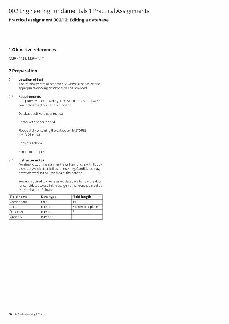
1 Objective references
1.129 – 1.134, 1.139 – 1.141
2 Preparation
2.1 Location of test
The training centre or other venue where supervision andappropriate working conditions will be provided.
2.2 Requirements
Computer system providing access to database software,connected together and switched on.
Database software user manual.
Printer with paper loaded.
Floppy disk containing the database file STORES(see 3.2 below).
Copy of section 6.
Pen, pencil, paper.
2.3 Instructor notes
For simplicity, this assignment is written for use with floppydisks to save electronic files for marking. Candidates may,however, work in the user area of the network.
You are required to create a new database to hold the datafor candidates to use in the assignments. You should set upthe database as follows:
002 Engineering Fundamentals 1 Practical AssignmentsPractical assignment 002/12: Editing a database
IVQ in Engineering 256558
Field name Data type Field length
Component text 14
Cost number 5 (2 decimal places)
Recorder number 3
Quantity number 4
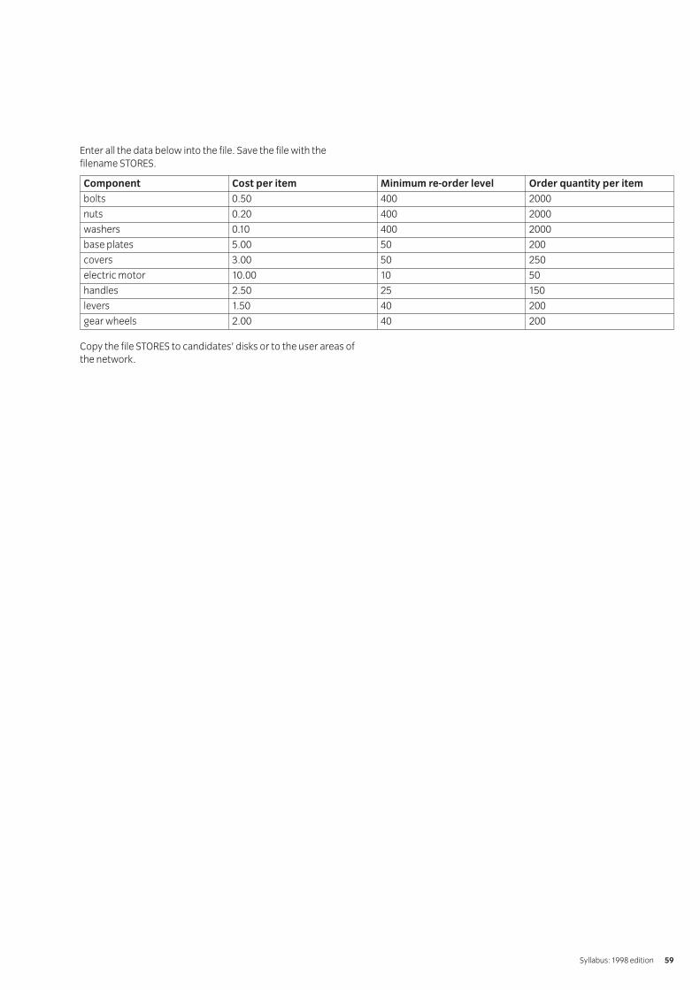
Enter all the data below into the file. Save the file with the filename STORES.
Copy the file STORES to candidates’ disks or to the user areas ofthe network.
Syllabus: 1998 edition 59
Component Cost per item Minimum re-order level Order quantity per item
bolts 0.50 400 2000
nuts 0.20 400 2000
washers 0.10 400 2000
base plates 5.00 50 200
covers 3.00 50 250
electric motor 10.00 10 50
handles 2.50 25 150
levers 1.50 40 200
gear wheels 2.00 40 200
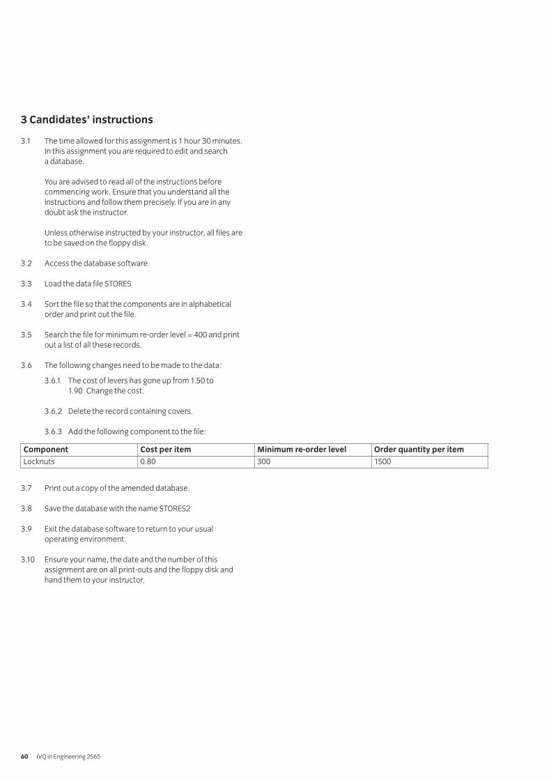
3 Candidates’ instructions
3.1 The time allowed for this assignment is 1 hour 30 minutes.In this assignment you are required to edit and search a database.
You are advised to read all of the instructions beforecommencing work. Ensure that you understand all theinstructions and follow them precisely. If you are in anydoubt ask the instructor.
Unless otherwise instructed by your instructor, all files areto be saved on the floppy disk.
3.2 Access the database software.
3.3 Load the data file STORES
3.4 Sort the file so that the components are in alphabeticalorder and print out the file.
3.5 Search the file for minimum re-order level = 400 and printout a list of all these records.
3.6 The following changes need to be made to the data:
3.6.1 The cost of levers has gone up from 1.50 to 1.90. Change the cost.
3.6.2 Delete the record containing covers.
3.6.3 Add the following component to the file:
3.7 Print out a copy of the amended database.
3.8 Save the database with the name STORES2
3.9 Exit the database software to return to your usualoperating environment.
3.10 Ensure your name, the date and the number of thisassignment are on all print-outs and the floppy disk andhand them to your instructor.
IVQ in Engineering 256560
Component Cost per item Minimum re-order level Order quantity per item
Locknuts 0.80 300 1500
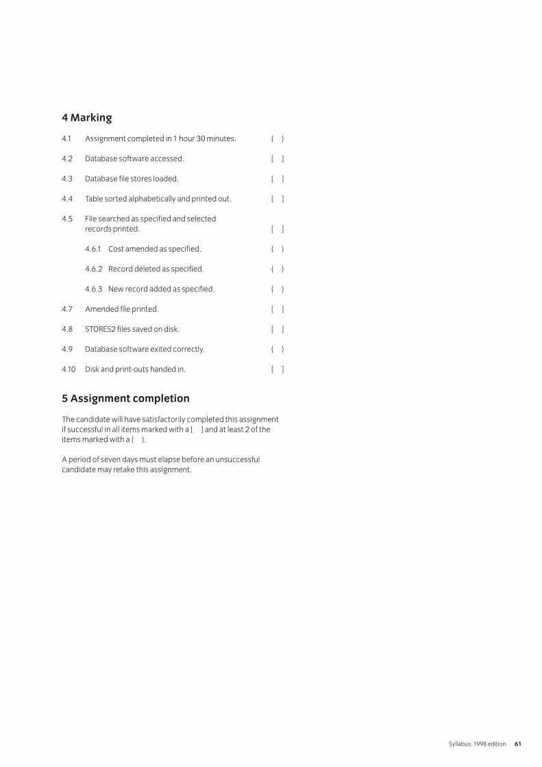
4 Marking
4.1 Assignment completed in 1 hour 30 minutes. ( )
4.2 Database software accessed. [ ]
4.3 Database file stores loaded. [ ]
4.4 Table sorted alphabetically and printed out. [ ]
4.5 File searched as specified and selected records printed. [ ]
4.6.1 Cost amended as specified. ( )
4.6.2 Record deleted as specified. ( )
4.6.3 New record added as specified. ( )
4.7 Amended file printed. [ ]
4.8 STORES2 files saved on disk. [ ]
4.9 Database software exited correctly. ( )
4.10 Disk and print-outs handed in. [ ]
5 Assignment completion
The candidate will have satisfactorily completed this assignmentif successful in all items marked with a [ ] and at least 2 of theitems marked with a ( ).
A period of seven days must elapse before an unsuccessfulcandidate may retake this assignment.
Syllabus: 1998 edition 61
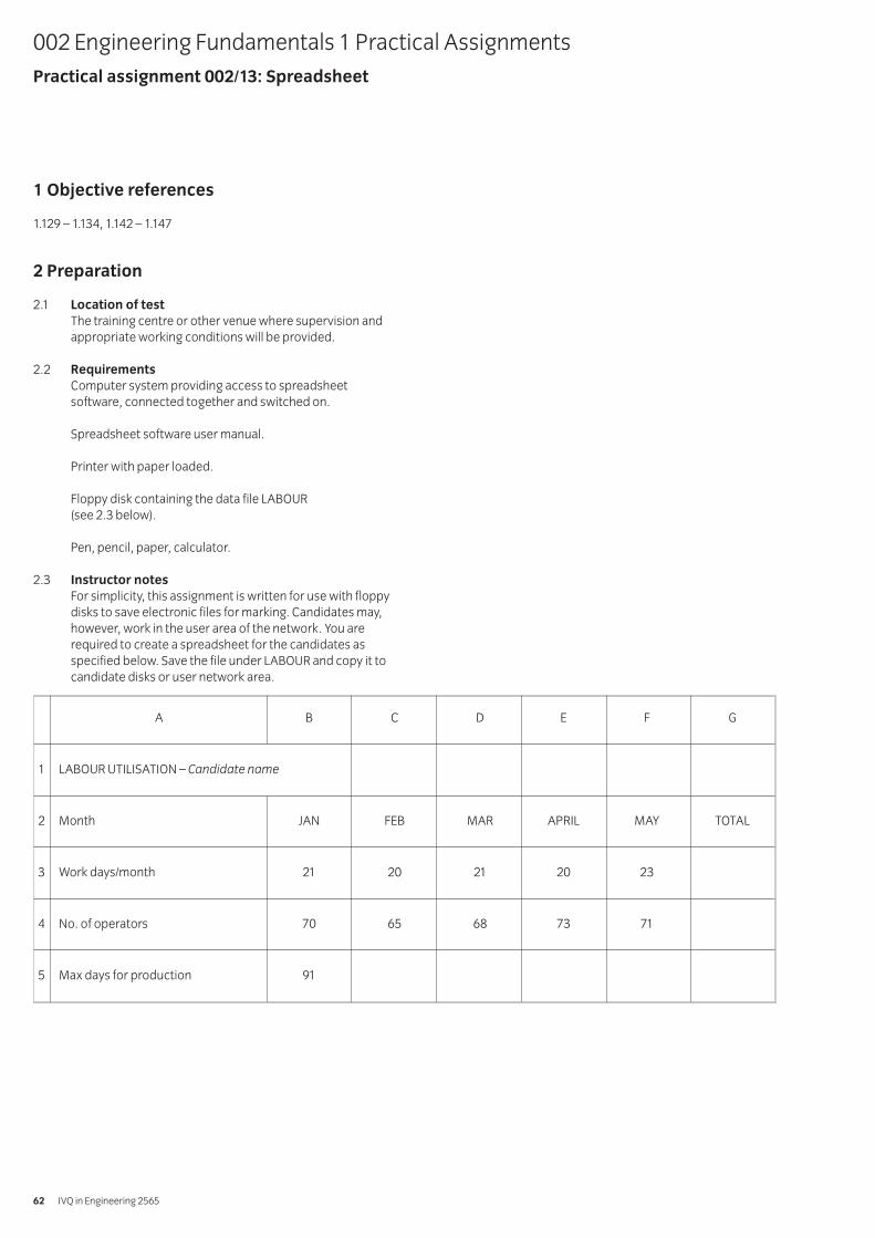
1 Objective references
1.129 – 1.134, 1.142 – 1.147
2 Preparation
2.1 Location of test
The training centre or other venue where supervision andappropriate working conditions will be provided.
2.2 Requirements
Computer system providing access to spreadsheetsoftware, connected together and switched on.
Spreadsheet software user manual.
Printer with paper loaded.
Floppy disk containing the data file LABOUR(see 2.3 below).
Pen, pencil, paper, calculator.
2.3 Instructor notes
For simplicity, this assignment is written for use with floppydisks to save electronic files for marking. Candidates may,however, work in the user area of the network. You arerequired to create a spreadsheet for the candidates asspecified below. Save the file under LABOUR and copy it tocandidate disks or user network area.
002 Engineering Fundamentals 1 Practical AssignmentsPractical assignment 002/13: Spreadsheet
IVQ in Engineering 256562
A B C D E F G
1 LABOUR UTILISATION – Candidate name
2 Month JAN FEB MAR APRIL MAY TOTAL
3 Work days/month 21 20 21 20 23
4 No. of operators 70 65 68 73 71
5 Max days for production 91
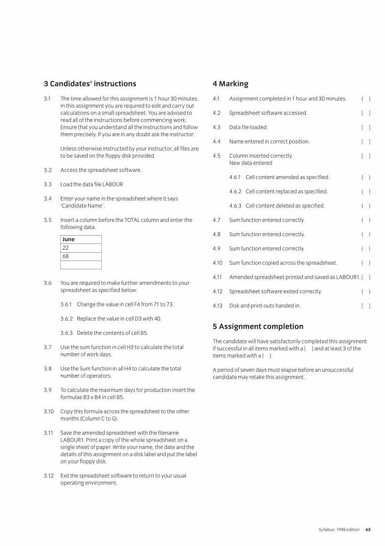
3 Candidates’ instructions
3.1 The time allowed for this assignment is 1 hour 30 minutes.In this assignment you are required to edit and carry outcalculations on a small spreadsheet. You are advised toread all of the instructions before commencing work.Ensure that you understand all the instructions and followthem precisely. If you are in any doubt ask the instructor.
Unless otherwise instructed by your instructor, all files areto be saved on the floppy disk provided.
3.2 Access the spreadsheet software.
3.3 Load the data file LABOUR
3.4 Enter your name in the spreadsheet where it says‘Candidate Name’.
3.5 Insert a column before the TOTAL column and enter thefollowing data.
3.6 You are required to make further amendments to yourspreadsheet as specified below:
3.6.1 Change the value in cell F4 from 71 to 73.
3.6.2 Replace the value in cell D3 with 40.
3.6.3 Delete the contents of cell B5.
3.7 Use the sum function in cell H3 to calculate the totalnumber of work days.
3.8 Use the Sum function in all H4 to calculate the total number of operators.
3.9 To calculate the maximum days for production insert theformulae B3 x B4 in cell B5.
3.10 Copy this formula across the spreadsheet to the othermonths (Column C to G).
3.11 Save the amended spreadsheet with the filenameLABOUR1. Print a copy of the whole spreadsheet on asingle sheet of paper. Write your name, the date and thedetails of this assignment on a disk label and put the labelon your floppy disk.
3.12 Exit the spreadsheet software to return to your usualoperating environment.
4 Marking
4.1 Assignment completed in 1 hour and 30 minutes. ( )
4.2 Spreadsheet software accessed. [ ]
4.3 Data file loaded. [ ]
4.4 Name entered in correct position. [ ]
4.5 Column inserted correctly. [ ]New data entered
4.6.1 Cell content amended as specified. ( )
4.6.2 Cell content replaced as specified. ( )
4.6.3 Cell content deleted as specified. ( )
4.7 Sum function entered correctly. ( )
4.8 Sum function entered correctly. ( )
4.9 Sum function entered correctly. ( )
4.10 Sum function copied across the spreadsheet. ( )
4.11 Amended spreadsheet printed and saved as LABOUR1. [ ]
4.12 Spreadsheet software exited correctly. ( )
4.13 Disk and print-outs handed in. [ ]
5 Assignment completion
The candidate will have satisfactorily completed this assignmentif successful in all items marked with a [ ] and at least 3 of theitems marked with a ( ).
A period of seven days must elapse before an unsuccessfulcandidate may retake this assignment.
Syllabus: 1998 edition 63
June
22
68
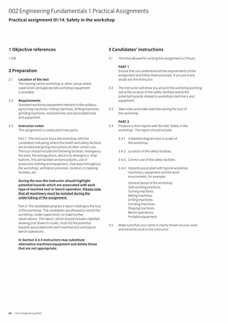
1 Objective references
1.158
2 Preparation
2.1 Location of the test
The training centre workshop or other venue wheresupervision and appropriate workshop equipment is available.
2.2 Requirements
Standard workshop equipment relevant to the syllabus, eg turning machines, milling machines, drilling machines,grinding machines, work benches and associated toolsand equipment.
2.3 Instructor notes
This assignment is conducted in two parts.
Part 1: The instructor tours the workshop with thecandidates indicating where the health and safety facilitiesare located and giving instructions on their correct use.The tour should include the following facilities: emergencyfire exits, fire extinguishers, electricity emergency ‘stop’buttons, first aid facilities and procedures, use ofprotective clothing and equipment, clearways throughoutthe workshop, ventilation provision, location of cleaningfacilities, etc.
During the tour the instructor should highlight
potential hazards which are associated with each
type of machine tool or bench operation. Please note
that all machinery must be isolated during the
undertaking of the assignment.
Part 2: The candidates prepare a report relating to the tourof the workshop. The candidates are allowed to revisit theworkshop, under supervision, to make furtherobservations. The report, which should include a labelleddrawing (not drawn to scale), must list the potentialhazards associated with each machine tool and typicalbench operations.
In Section 3.4.4 instructors may substitute
alternative machines/equipment and delete those
that are not appropriate.
3 Candidates’ instructions
3.1 The time allowed for writing this assignment is 2 hours.
PART 1
Ensure that you understand all the requirements of theassignment and follow them precisely. If you are in anydoubt ask the instructor.
3.2 The instructor will show you around the workshop pointingout a) the location of the safety facilities and b) thepotential hazards related to workshop machinery andequipment.
3.3 Take notes and make sketches during the tour of the workshop.
PART 2
3.4 Produce a short report with the title ‘Safety in theworkshop’. The report should include:
3.4.1 A labelled diagram (not to scale) of the workshop.
3.4.2 Location of the safety facilities.
3.4.3. Correct use of the safety facilities.
3.4.4. Hazards associated with typical workshop machinery, equipment and the work environment, for example:
General layout of the workshop.Safe working practices.Turning machines.Milling machines.Drilling machines.Grinding machines.Shaping machines.Bench operations.Portable equipment.
3.5 Make sure that your name is clearly shown on your workand hand the work to the instructor.
002 Engineering Fundamentals 1 Practical AssignmentsPractical assignment 01/14: Safety in the workshop
IVQ in Engineering 256564
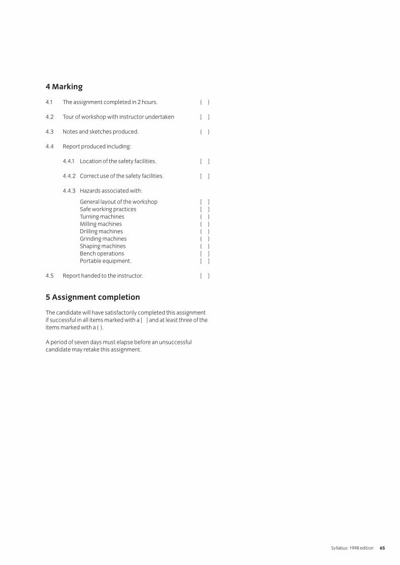
4 Marking
4.1 The assignment completed in 2 hours. ( )
4.2 Tour of workshop with instructor undertaken [ ]
4.3 Notes and sketches produced. ( )
4.4 Report produced including:
4.4.1 Location of the safety facilities. [ ]
4.4.2 Correct use of the safety facilities. [ ]
4.4.3 Hazards associated with:
General layout of the workshop [ ]Safe working practices [ ]Turning machines ( )Milling machines ( )Drilling machines ( )Grinding machines ( )Shaping machines ( )Bench operations [ ]Portable equipment. [ ]
4.5 Report handed to the instructor. [ ]
5 Assignment completion
The candidate will have satisfactorily completed this assignmentif successful in all items marked with a [ ] and at least three of theitems marked with a ( ).
A period of seven days must elapse before an unsuccessfulcandidate may retake this assignment.
Syllabus: 1998 edition 65
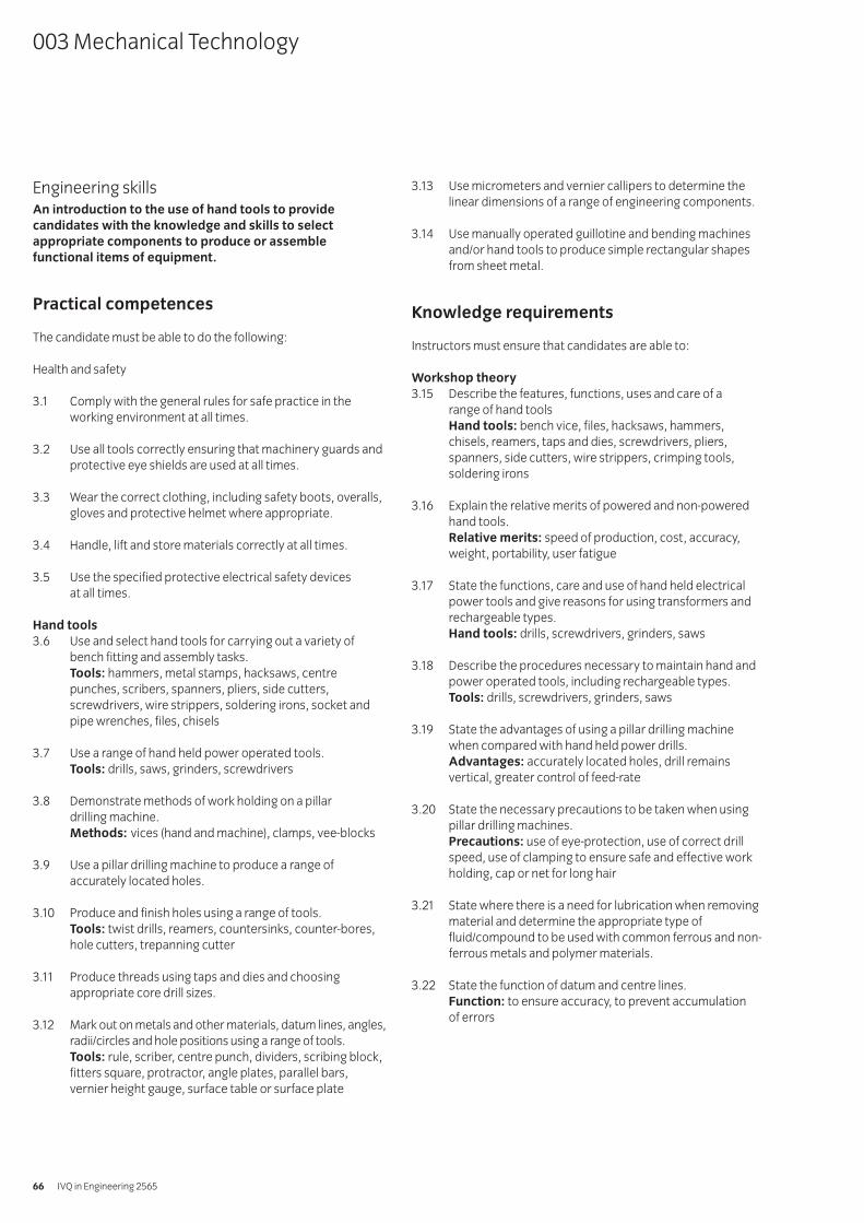
Engineering skillsAn introduction to the use of hand tools to provide
candidates with the knowledge and skills to select
appropriate components to produce or assemble
functional items of equipment.
Practical competences
The candidate must be able to do the following:
Health and safety
3.1 Comply with the general rules for safe practice in theworking environment at all times.
3.2 Use all tools correctly ensuring that machinery guards andprotective eye shields are used at all times.
3.3 Wear the correct clothing, including safety boots, overalls,gloves and protective helmet where appropriate.
3.4 Handle, lift and store materials correctly at all times.
3.5 Use the specified protective electrical safety devices at all times.
Hand tools
3.6 Use and select hand tools for carrying out a variety ofbench fitting and assembly tasks.Tools: hammers, metal stamps, hacksaws, centrepunches, scribers, spanners, pliers, side cutters,screwdrivers, wire strippers, soldering irons, socket andpipe wrenches, files, chisels
3.7 Use a range of hand held power operated tools.Tools: drills, saws, grinders, screwdrivers
3.8 Demonstrate methods of work holding on a pillar drilling machine.Methods: vices (hand and machine), clamps, vee-blocks
3.9 Use a pillar drilling machine to produce a range ofaccurately located holes.
3.10 Produce and finish holes using a range of tools.Tools: twist drills, reamers, countersinks, counter-bores,hole cutters, trepanning cutter
3.11 Produce threads using taps and dies and choosingappropriate core drill sizes.
3.12 Mark out on metals and other materials, datum lines, angles,radii/circles and hole positions using a range of tools.Tools: rule, scriber, centre punch, dividers, scribing block,fitters square, protractor, angle plates, parallel bars,vernier height gauge, surface table or surface plate
3.13 Use micrometers and vernier callipers to determine thelinear dimensions of a range of engineering components.
3.14 Use manually operated guillotine and bending machinesand/or hand tools to produce simple rectangular shapesfrom sheet metal.
Knowledge requirements
Instructors must ensure that candidates are able to:
Workshop theory
3.15 Describe the features, functions, uses and care of a range of hand toolsHand tools: bench vice, files, hacksaws, hammers,chisels, reamers, taps and dies, screwdrivers, pliers,spanners, side cutters, wire strippers, crimping tools,soldering irons
3.16 Explain the relative merits of powered and non-poweredhand tools.Relative merits: speed of production, cost, accuracy,weight, portability, user fatigue
3.17 State the functions, care and use of hand held electricalpower tools and give reasons for using transformers andrechargeable types.Hand tools: drills, screwdrivers, grinders, saws
3.18 Describe the procedures necessary to maintain hand andpower operated tools, including rechargeable types.Tools: drills, screwdrivers, grinders, saws
3.19 State the advantages of using a pillar drilling machinewhen compared with hand held power drills.Advantages: accurately located holes, drill remainsvertical, greater control of feed-rate
3.20 State the necessary precautions to be taken when usingpillar drilling machines.Precautions: use of eye-protection, use of correct drillspeed, use of clamping to ensure safe and effective workholding, cap or net for long hair
3.21 State where there is a need for lubrication when removingmaterial and determine the appropriate type offluid/compound to be used with common ferrous and non-ferrous metals and polymer materials.
3.22 State the function of datum and centre lines.Function: to ensure accuracy, to prevent accumulation of errors
003 Mechanical Technology
IVQ in Engineering 256566
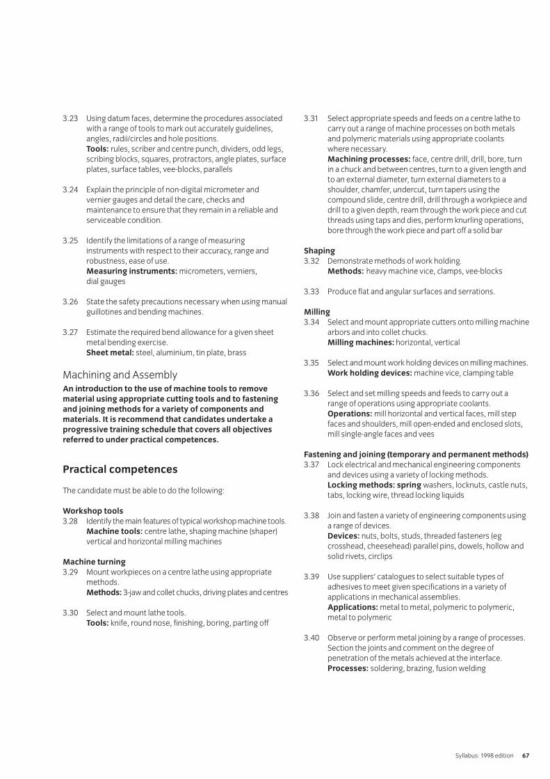
3.23 Using datum faces, determine the procedures associatedwith a range of tools to mark out accurately guidelines,angles, radii/circles and hole positions.Tools: rules, scriber and centre punch, dividers, odd legs,scribing blocks, squares, protractors, angle plates, surfaceplates, surface tables, vee-blocks, parallels
3.24 Explain the principle of non-digital micrometer and vernier gauges and detail the care, checks andmaintenance to ensure that they remain in a reliable andserviceable condition.
3.25 Identify the limitations of a range of measuring instruments with respect to their accuracy, range androbustness, ease of use.Measuring instruments: micrometers, verniers, dial gauges
3.26 State the safety precautions necessary when using manualguillotines and bending machines.
3.27 Estimate the required bend allowance for a given sheetmetal bending exercise.Sheet metal: steel, aluminium, tin plate, brass
Machining and AssemblyAn introduction to the use of machine tools to remove
material using appropriate cutting tools and to fastening
and joining methods for a variety of components and
materials. It is recommend that candidates undertake a
progressive training schedule that covers all objectives
referred to under practical competences.
Practical competences
The candidate must be able to do the following:
Workshop tools
3.28 Identify the main features of typical workshop machine tools.Machine tools: centre lathe, shaping machine (shaper)vertical and horizontal milling machines
Machine turning
3.29 Mount workpieces on a centre lathe using appropriatemethods.Methods: 3-jaw and collet chucks, driving plates and centres
3.30 Select and mount lathe tools.Tools: knife, round nose, finishing, boring, parting off
3.31 Select appropriate speeds and feeds on a centre lathe tocarry out a range of machine processes on both metalsand polymeric materials using appropriate coolants where necessary.Machining processes: face, centre drill, drill, bore, turnin a chuck and between centres, turn to a given length andto an external diameter, turn external diameters to ashoulder, chamfer, undercut, turn tapers using thecompound slide, centre drill, drill through a workpiece anddrill to a given depth, ream through the work piece and cutthreads using taps and dies, perform knurling operations,bore through the work piece and part off a solid bar
Shaping
3.32 Demonstrate methods of work holding.Methods: heavy machine vice, clamps, vee-blocks
3.33 Produce flat and angular surfaces and serrations.
Milling
3.34 Select and mount appropriate cutters onto milling machinearbors and into collet chucks.Milling machines: horizontal, vertical
3.35 Select and mount work holding devices on milling machines.Work holding devices: machine vice, clamping table
3.36 Select and set milling speeds and feeds to carry out arange of operations using appropriate coolants.Operations: mill horizontal and vertical faces, mill stepfaces and shoulders, mill open-ended and enclosed slots,mill single-angle faces and vees
Fastening and joining (temporary and permanent methods)
3.37 Lock electrical and mechanical engineering componentsand devices using a variety of locking methods.Locking methods: spring washers, locknuts, castle nuts,tabs, locking wire, thread locking liquids
3.38 Join and fasten a variety of engineering components usinga range of devices.Devices: nuts, bolts, studs, threaded fasteners (egcrosshead, cheesehead) parallel pins, dowels, hollow andsolid rivets, circlips
3.39 Use suppliers’ catalogues to select suitable types ofadhesives to meet given specifications in a variety ofapplications in mechanical assemblies.Applications: metal to metal, polymeric to polymeric,metal to polymeric
3.40 Observe or perform metal joining by a range of processes.Section the joints and comment on the degree ofpenetration of the metals achieved at the interface.Processes: soldering, brazing, fusion welding
Syllabus: 1998 edition 67
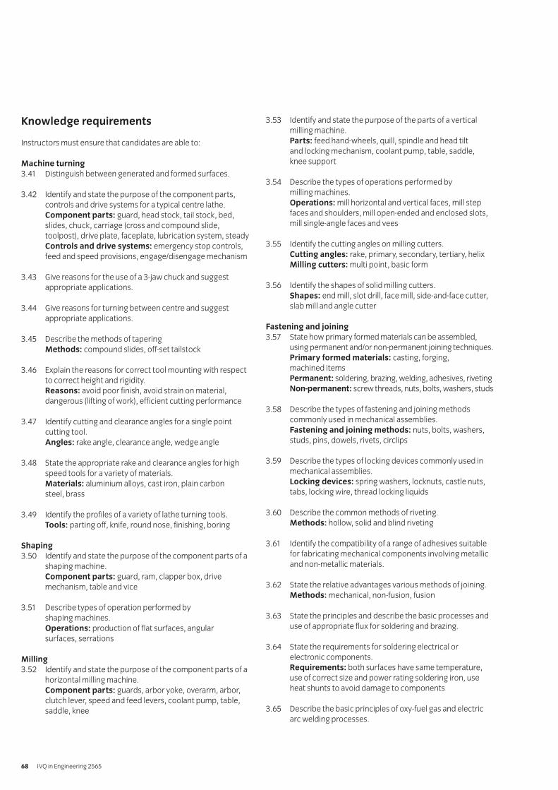
Knowledge requirements
Instructors must ensure that candidates are able to:
Machine turning
3.41 Distinguish between generated and formed surfaces.
3.42 Identify and state the purpose of the component parts,controls and drive systems for a typical centre lathe.Component parts: guard, head stock, tail stock, bed,slides, chuck, carriage (cross and compound slide,toolpost), drive plate, faceplate, lubrication system, steadyControls and drive systems: emergency stop controls,feed and speed provisions, engage/disengage mechanism
3.43 Give reasons for the use of a 3-jaw chuck and suggestappropriate applications.
3.44 Give reasons for turning between centre and suggestappropriate applications.
3.45 Describe the methods of taperingMethods: compound slides, off-set tailstock
3.46 Explain the reasons for correct tool mounting with respectto correct height and rigidity.Reasons: avoid poor finish, avoid strain on material,dangerous (lifting of work), efficient cutting performance
3.47 Identify cutting and clearance angles for a single pointcutting tool.Angles: rake angle, clearance angle, wedge angle
3.48 State the appropriate rake and clearance angles for highspeed tools for a variety of materials.Materials: aluminium alloys, cast iron, plain carbon steel, brass
3.49 Identify the profiles of a variety of lathe turning tools.Tools: parting off, knife, round nose, finishing, boring
Shaping
3.50 Identify and state the purpose of the component parts of ashaping machine.Component parts: guard, ram, clapper box, drivemechanism, table and vice
3.51 Describe types of operation performed by shaping machines.Operations: production of flat surfaces, angular surfaces, serrations
Milling
3.52 Identify and state the purpose of the component parts of ahorizontal milling machine.Component parts: guards, arbor yoke, overarm, arbor,clutch lever, speed and feed levers, coolant pump, table,saddle, knee
3.53 Identify and state the purpose of the parts of a verticalmilling machine.Parts: feed hand-wheels, quill, spindle and head tilt and locking mechanism, coolant pump, table, saddle, knee support
3.54 Describe the types of operations performed by milling machines.Operations: mill horizontal and vertical faces, mill stepfaces and shoulders, mill open-ended and enclosed slots,mill single-angle faces and vees
3.55 Identify the cutting angles on milling cutters.Cutting angles: rake, primary, secondary, tertiary, helixMilling cutters: multi point, basic form
3.56 Identify the shapes of solid milling cutters.Shapes: end mill, slot drill, face mill, side-and-face cutter,slab mill and angle cutter
Fastening and joining
3.57 State how primary formed materials can be assembled,using permanent and/or non-permanent joining techniques.Primary formed materials: casting, forging, machined itemsPermanent: soldering, brazing, welding, adhesives, rivetingNon-permanent: screw threads, nuts, bolts, washers, studs
3.58 Describe the types of fastening and joining methodscommonly used in mechanical assemblies.Fastening and joining methods: nuts, bolts, washers,studs, pins, dowels, rivets, circlips
3.59 Describe the types of locking devices commonly used inmechanical assemblies.Locking devices: spring washers, locknuts, castle nuts,tabs, locking wire, thread locking liquids
3.60 Describe the common methods of riveting.Methods: hollow, solid and blind riveting
3.61 Identify the compatibility of a range of adhesives suitablefor fabricating mechanical components involving metallicand non-metallic materials.
3.62 State the relative advantages various methods of joining.Methods: mechanical, non-fusion, fusion
3.63 State the principles and describe the basic processes anduse of appropriate flux for soldering and brazing.
3.64 State the requirements for soldering electrical orelectronic components.Requirements: both surfaces have same temperature,use of correct size and power rating soldering iron, useheat shunts to avoid damage to components
3.65 Describe the basic principles of oxy-fuel gas and electricarc welding processes.
IVQ in Engineering 256568
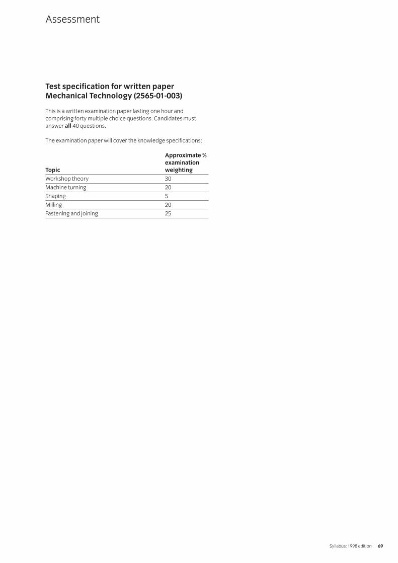
Test specification for written paperMechanical Technology (2565-01-003)
This is a written examination paper lasting one hour andcomprising forty multiple choice questions. Candidates mustanswer all 40 questions.
The examination paper will cover the knowledge specifications:
Approximate %
examination
Topic weighting
Workshop theory 30
Machine turning 20
Shaping 5
Milling 20
Fastening and joining 25
Assessment
Syllabus: 1998 edition 69
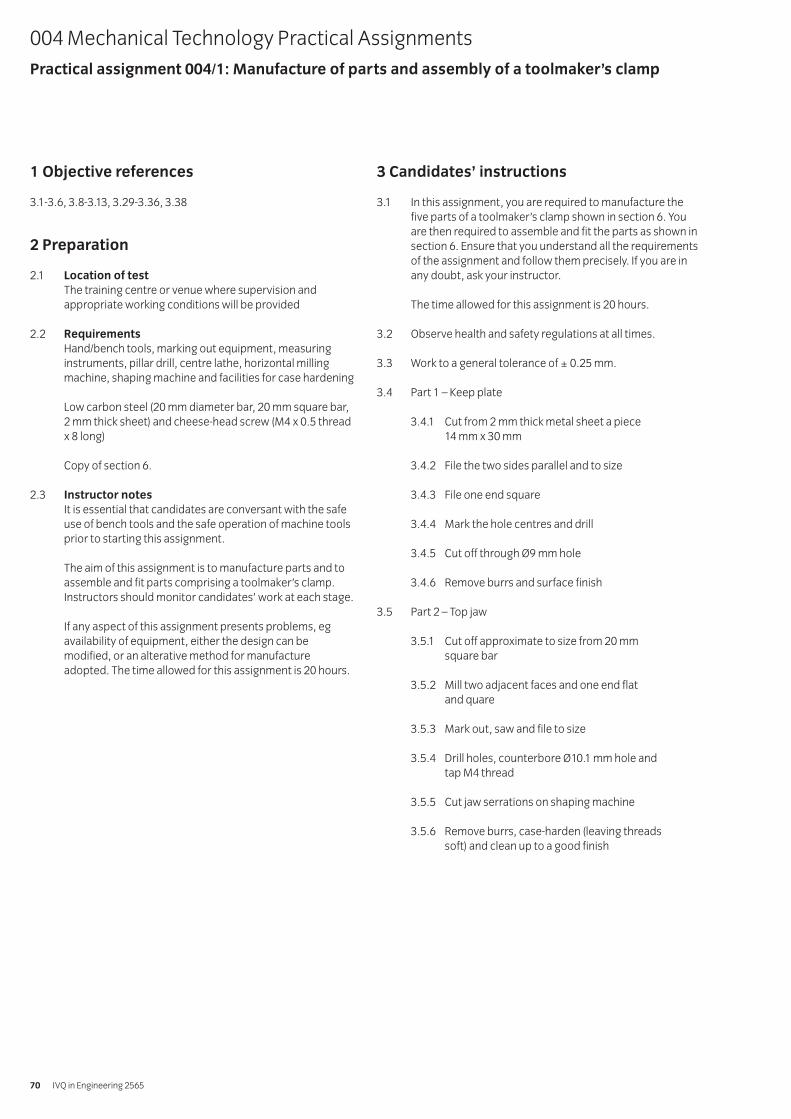
1 Objective references
3.1-3.6, 3.8-3.13, 3.29-3.36, 3.38
2 Preparation
2.1 Location of test
The training centre or venue where supervision andappropriate working conditions will be provided
2.2 Requirements
Hand/bench tools, marking out equipment, measuringinstruments, pillar drill, centre lathe, horizontal millingmachine, shaping machine and facilities for case hardening
Low carbon steel (20 mm diameter bar, 20 mm square bar,2 mm thick sheet) and cheese-head screw (M4 x 0.5 threadx 8 long)
Copy of section 6.
2.3 Instructor notes
It is essential that candidates are conversant with the safeuse of bench tools and the safe operation of machine toolsprior to starting this assignment.
The aim of this assignment is to manufacture parts and toassemble and fit parts comprising a toolmaker’s clamp.Instructors should monitor candidates’ work at each stage.
If any aspect of this assignment presents problems, egavailability of equipment, either the design can bemodified, or an alterative method for manufactureadopted. The time allowed for this assignment is 20 hours.
3 Candidates’ instructions
3.1 In this assignment, you are required to manufacture thefive parts of a toolmaker’s clamp shown in section 6. Youare then required to assemble and fit the parts as shown insection 6. Ensure that you understand all the requirementsof the assignment and follow them precisely. If you are inany doubt, ask your instructor.
The time allowed for this assignment is 20 hours.
3.2 Observe health and safety regulations at all times.
3.3 Work to a general tolerance of ± 0.25 mm.
3.4 Part 1 – Keep plate
3.4.1 Cut from 2 mm thick metal sheet a piece 14 mm x 30 mm
3.4.2 File the two sides parallel and to size
3.4.3 File one end square
3.4.4 Mark the hole centres and drill
3.4.5 Cut off through Ø9 mm hole
3.4.6 Remove burrs and surface finish
3.5 Part 2 – Top jaw
3.5.1 Cut off approximate to size from 20 mm square bar
3.5.2 Mill two adjacent faces and one end flat and quare
3.5.3 Mark out, saw and file to size
3.5.4 Drill holes, counterbore Ø10.1 mm hole and tap M4 thread
3.5.5 Cut jaw serrations on shaping machine
3.5.6 Remove burrs, case-harden (leaving threads soft) and clean up to a good finish
004 Mechanical Technology Practical AssignmentsPractical assignment 004/1: Manufacture of parts and assembly of a toolmaker’s clamp
IVQ in Engineering 256570
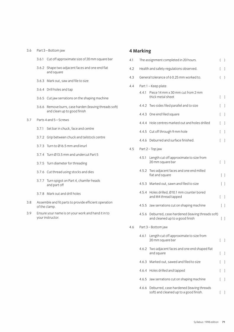
3.6 Part 3 – Bottom jaw
3.6.1 Cut off approximate size of 20 mm square bar
3.6.2 Shape two adjacent faces and one end flat and square
3.6.3 Mark out, saw and file to size
3.6.4 Drill holes and tap
3.6.5 Cut jaw serrations on the shaping machine
3.6.6 Remove burrs, case harden (leaving threads soft)and clean up to good finish
3.7 Parts 4 and 5 – Screws
3.7.1 Set bar in chuck, face and centre
3.7.2 Grip between chuck and tailstock centre
3.7.3 Turn to Ø16.5 mm and knurl
3.7.4 Turn Ø13.5 mm and undercut Part 5
3.7.5 Turn diameter for threading
3.7.6 Cut thread using stocks and dies
3.7.7 Turn spigot on Part 4, chamfer heads and part off
3.7.8 Mark out and drill holes
3.8 Assemble and fit parts to provide efficient operation of the clamp.
3.9 Ensure your name is on your work and hand it in to your instructor.
4 Marking
4.1 The assignment completed in 20 hours. ( )
4.2 Health and safety regulations observed. [ ]
4.3 General tolerance of 6 0.25 mm worked to. ( )
4.4 Part 1 – Keep plate
4.4.1 Piece 14 mm x 30 mm cut from 2 mm thick metal sheet [ ]
4.4.2 Two sides filed parallel and to size [ ]
4.4.3 One end filed square [ ]
4.4.4 Hole centres marked out and holes drilled [ ]
4.4.5 Cut off through 9 mm hole [ ]
4.4.6 Deburred and surface finished. [ ]
4.5 Part 2 – Top jaw
4.5.1 Length cut off approximate to size from 20 mm square bar [ ]
4.5.2 Two adjacent faces and one end milled flat and square [ ]
4.5.3 Marked out, sawn and filed to size [ ]
4.5.4 Holes drilled, Ø10.1 mm counter bored and M4 thread tapped [ ]
4.5.5 Jaw serrations cut on shaping machine [ ]
4.5.6 Deburred, case-hardened (leaving threads soft) and cleaned up to a good finish [ ]
4.6 Part 3 – Bottom jaw
4.6.1 Length cut off approximate to size from 20 mm square bar [ ]
4.6.2 Two adjacent faces and one end shaped flat and square [ ]
4.6.3 Marked out, sawed and filed to size [ ]
4.6.4 Holes drilled and tapped [ ]
4.6.5 Jaw serrations cut on shaping machine [ ]
4.6.6 Deburred, case-hardened (leaving threads soft) and cleaned up to a good finish. [ ]
Syllabus: 1998 edition 71

4.7 Parts 4 and 5 – Screws
4.7.1 Bar set in chuck faced and centred [ ]
4.7.2 Gripped between chuck and tail stock centre [ ]
4.7.3 Turned to Ø16.5 mm and knurled [ ]
4.7.4 Turned to Ø13.5 mm and Part 5 under cut [ ]
4.7.5 Diameter turned for threading [ ]
4.7.6 Thread cut using stocks and dies [ ]
4.7.7 Spigot turned on Part 4, heads chamfered and screws parted off [ ]
4.7.8 Holes marked out and drilled [ ]
4.8 Clamp assembled and parts filled to provide efficientoperation. [ ]
4.9 Work handed to instructor. [ ]
5 Assignment completion
5.1 The candidate will have satisfactorily completed thisassignment if successful in all items marked with a [ ].Candidates should be encouraged to redo/modify theirwork until they reach an acceptable standard.
IVQ in Engineering 256572
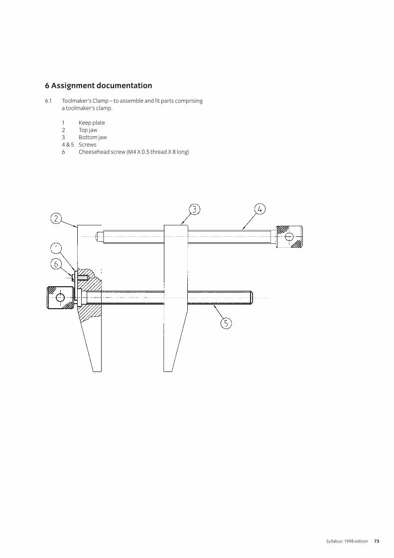
6 Assignment documentation
6.1 Toolmaker’s Clamp – to assemble and fit parts comprisinga toolmaker’s clamp.
1 Keep plate2 Top jaw3 Bottom jaw4 & 5 Screws6 Cheesehead screw (M4 X 0.5 thread X 8 long)
Syllabus: 1998 edition 73
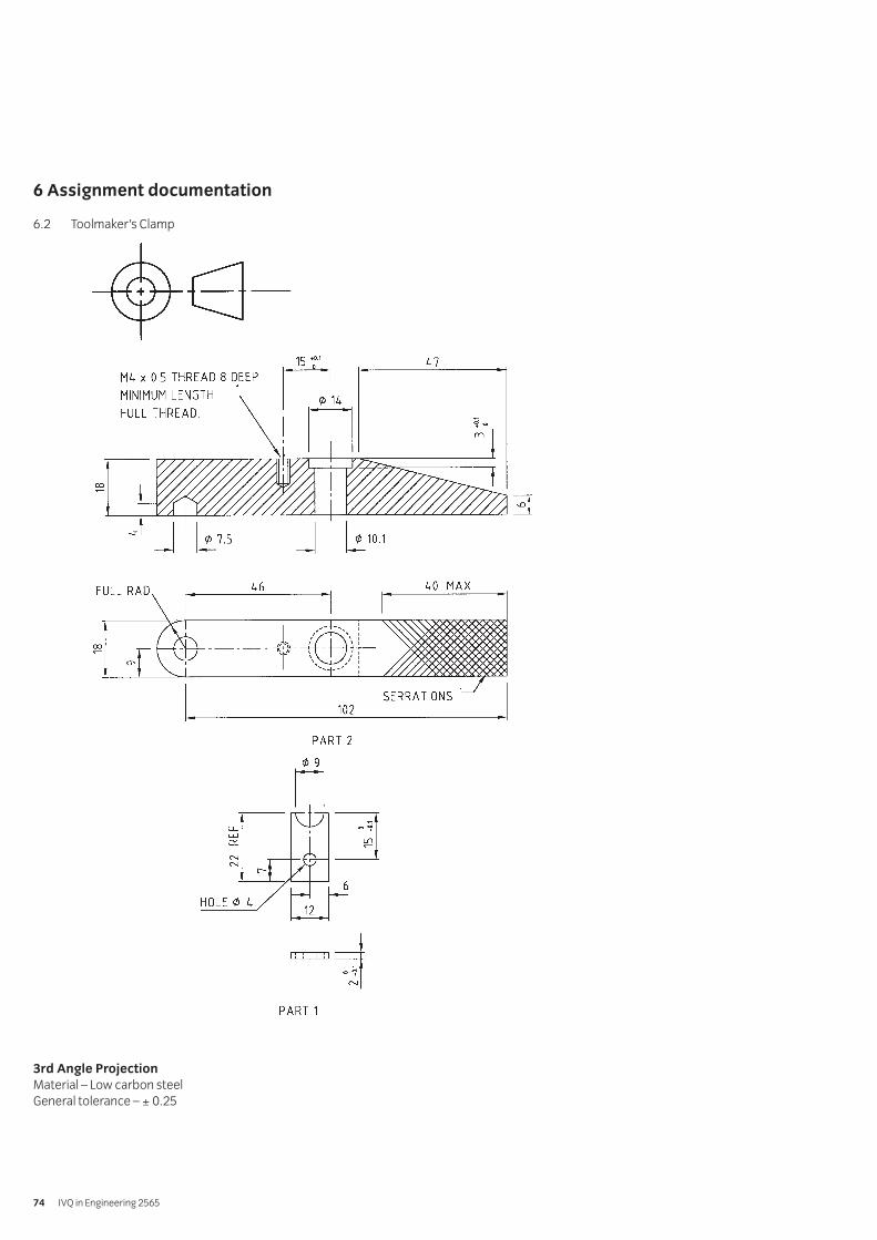
6 Assignment documentation
6.2 Toolmaker’s Clamp
3rd Angle Projection
Material – Low carbon steelGeneral tolerance – ± 0.25
IVQ in Engineering 256574
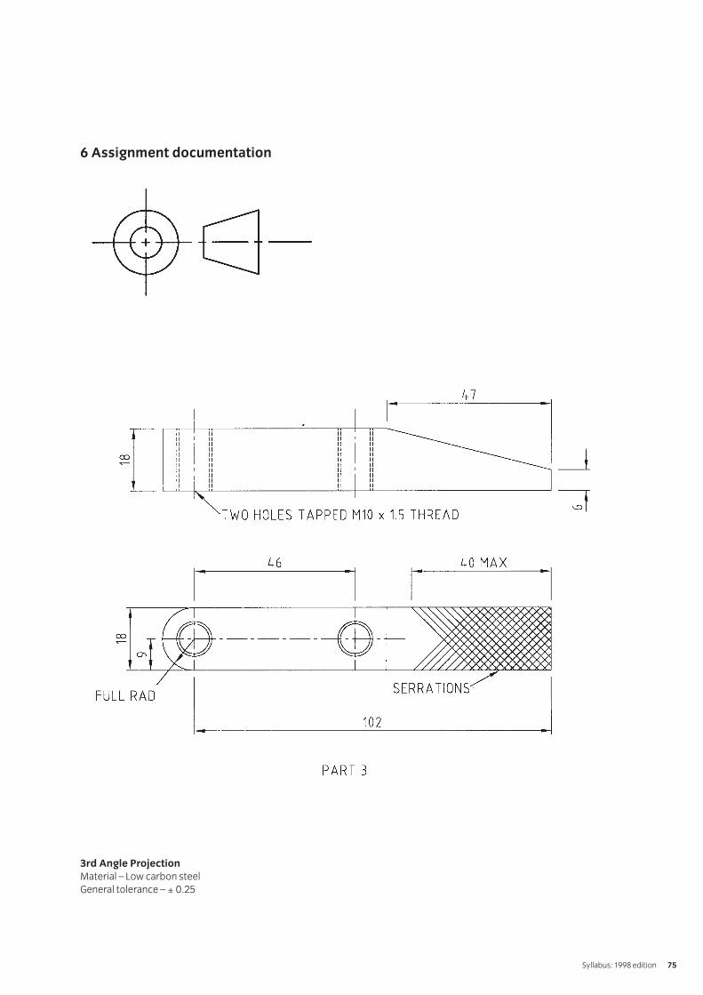
6 Assignment documentation
3rd Angle Projection
Material – Low carbon steelGeneral tolerance – ± 0.25
Syllabus: 1998 edition 75
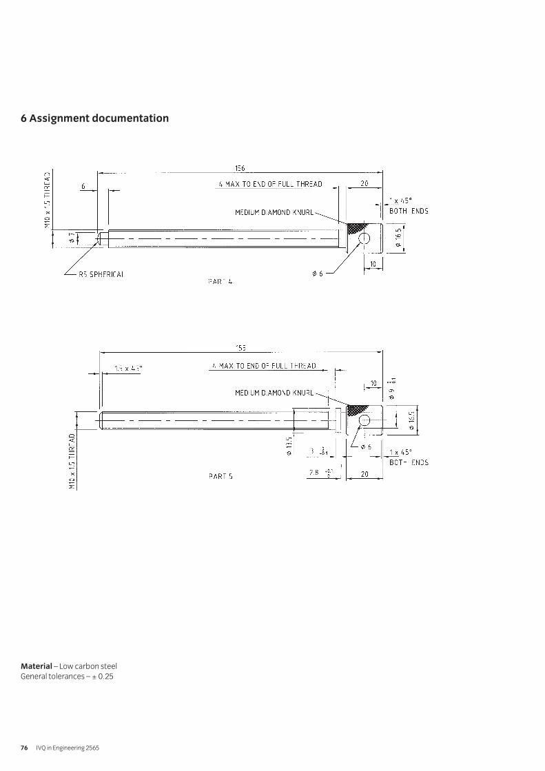
6 Assignment documentation
Material – Low carbon steelGeneral tolerances – ± 0.25
IVQ in Engineering 256576
1 Objective references
3.6
2 Preparation
2.1 Location of the test
The training centre workshop or other venue wheresupervision and appropriate work shop equipment isavailable.
2.2 Requirements
Standard workshop equipment including such as a centrelathe, shaping machine (shaper), vertical and horizontalmilling machines, pillar drill.
2.3 Instructor notes
The aim of this assignment is to identify the main featuresof typical workshop machine tools. The assignment can beconducted on any typical workshop machine tool. It isrecommended that a group of candidates will be given thisassignment and each member of the group will beallocated a particular machine tool.
The candidates have a list of questions relating to anaspect of the machine tool. The candidate must note theanswer or the information gained.
The electrical power and compressed air supply to
the workshop equipment must be isolated before
the assignment can be undertaken.
The time allowed for this assignment is 2 hours.
3 Candidates’ instructions
3.1 The time allowed for this assignment is 2 hours. You are required to investigate the main features of a typicalworkshop machine tool allocated to you by your instructor. If you are not clear about this assignment thenask your instructor.
You MUST NOT attempt to switch on the electrical
power to the machine tools whilst undertaking
this assignment.
3.2 Your task is to find out the information about yourworkshop machine tool by answering the questions listedbelow. Write down your answers.
3.2.1 Identify the type of machine tool and the name ofthe manufacturer.
3.2.2 Identify the safety devices fitted to the machine tool.
3.2.3 State the maximum size of work-piece the machinetool can hold.
3.2.4 If the machine tool has taper, state the type and size.
3.2.5 State the electrical rating of the main drive motor.
3.2.6 State the type of drive from the motor to the spindle.
3.2.7 State the range of spindle speeds available.
3.2.8 Observe the range of spindle speeds, is there any particular sequence?
3.2.9 List the various machining operations which can beconducted on the machine tool.
3.2.10 Explain how the feed system operates.
3.2.11 Identify the material the machine tool structure is made of.
3.2.12 Sketch, if possible, a cross section of the machinebed or column.
3.2.13 Identify the type of cutting fluid being used.
3.2.14 Determine the type of pump drive used for thecutting fluid.
3.2.15 List the work-holding devices which can be used on the machine tool.
3.2.16 List the tool holding devices which can be used onthe machine tool.
004 Mechanical Technology Practical AssignmentsPractical assignment 004/2: Identification of the main features of typical workshop machine tools
Syllabus: 1998 edition 77
3.2.17 List the auxiliary equipment which can be used onthe machine tool.
3.2.18 What provision is there to ensure the cutting tool is set correctly?
3.3 Make sure that your name is clearly shown on your workand hand it in to the instructor.
4 Marking
4.1. The assignment completed in 2 hours. ( )
4.2. The following information obtained:
4.2.1 The type of machine tool and the name of themanufacturer identified. ( )
4.2.2 The safety devices, which are fitted to the machine tool, identified. ( )
4.2.3 The maximum size of work-piece the machine tool can hold stated. ( )
4.2.4 The type and size of taper stated. ( )
4.2.5 The electrical rating of the main drive motor stated. ( )
4.2.6 The type of drive from the motor to the spindle stated. ( )
4.2.7 The range of spindle speeds available stated. ( )
4.2.8 The range of spindle speeds, and sequence stated. ( )
4.2.9 The various machining operations that can beconducted on the machine tool listed. ( )
4.2.10 The operation of the feed system explained. ( )
4.2.11 The material of the machine tool structure identified. ( )
4.2.12 The cross section of the machine bed or column sketched. ( )
4.2.13 The cutting fluid identified. ( )
4.2.14 The type of pump drive determined. ( )
4.2.15 The work-holding devices, used on the machine tool, listed. ( )
4.2.16 The tool holding devices, used on the machine tool, listed. ( )
4.2.17 The auxiliary equipment, used on the machine tool, listed. ( )
4.2.18 The provision for ensuring the cutting tool is set correctly described. ( )
4.3 Work handed to the instructor. [ ]
5 Assignment completion
The candidate will have satisfactorily completed this assignmentif successful in all items marked with a [ ] and at least 15 of theitems marked with a ( ).
IVQ in Engineering 256578
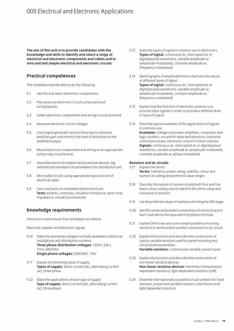
The aim of this unit is to provide candidates with the
knowledge and skills to identify and select a range of
electrical and electronic components and cables and to
wire and test simple electrical and electronic circuits.
Practical competences
The candidate must be able to do the following:
5.1 Identify and select electronic components.
5.2 Plan practical electronic circuit component and wiring layouts.
5.3 Solder electronic components and wiring to a circuit board.
5.4 Measure electronic circuit voltages.
5.5 Use a signal generator and oscilloscope to measureamplifier gain and monitor the level of distortion on theamplified output.
5.6 Mount electrical components and wiring on an appropriatesurface (eg circuit board).
5.7 Assemble electrical isolation and protective devices, (egswitches and miniature circuit breakers) into distribution unit.
5.8 Wire radial circuits using appropriate type and size ofelectrical cable.
5.9 Carry out tests on completed electrical circuit.Tests: polarity, continuity, insulation resistance, earth-loopimpedance, overall functional test
Knowledge requirements
Instructors must ensure that candidates are able to:
Electrical supplies and electronic signals
5.10 State the operating voltages normally available in electricalinstallations and distribution systems.Three phase distribution voltages: 132kV, 33kV, 11kV, 400/415V Single phase voltages: 230/240V, 110V
5.11 Explain the following types of supply.Types of supply: direct current (dc), alternating current(ac), three phase
5.12 State the applications of each type of supply.Type of supply: direct current (dc), alternating current(ac), three phase
5.13 State the types of signal in common use in electronics.Types of signal: continuous dc, interrupted dc ordigital/pulsed waveforms, variable amplitude ac(amplitude modulated), constant amplitude ac (frequency modulated)
5.14 Sketch graphs of amplitude/time to illustrate the nature of different types of signal.Types of signal: continuous dc, interrupted dc ordigital/pulsed waveforms, variable amplitude ac(amplitude modulated), constant amplitude ac (frequency modulated)
5.15 Explain that the function of electronic systems is toprocess input signals in order to provide a different level or type of output.
5.16 Describe typical examples of the applications of signals in common use.Examples: voltage and power amplifiers, computers andlogic systems, am and fm radio and television, industrialcontrol processes, electronic control in motor vehiclesSignals: continuous dc, interrupted dc or digital/pulsedwaveforms, variable amplitude ac (amplitude modulated),constant amplitude ac (phase modulated)
Resistors and dc circuits
5.17 Explain the terms.Terms: tolerance, power rating, stability, colour andnumerical coding and preferred value ranges
5.18 Describe the system of numerical and both four and fiveband colour coding used to identify the ohmic value andtolerance of resistors.
5.19 List the preferred values of resistance forming the 10% range.
5.20 Identify series and parallel connections of resistors and ineach case derive the equivalent resistance formula.
5.21 Explain Ohm’s law and solve simple problems involvingresistors in series and/or parallel connected in a dc circuit.
5.22 Explain the function and describe the construction oftypical variable resistors used for panel mounting andcircuit board assemblies.Variable resistors: continuously variable, preset types
5.23 Explain the function and describe the construction of non-linear resistive devices.Non-linear resistive devices: thermistor (temperaturedependent resistors), light dependent resistors (LDR)
5.24 Draw the internationally accepted circuit symbols for fixedresistors, preset and variable resistors, thermistors andlight dependent resistors.
005 Electrical and Electronic Applications
Syllabus: 1998 edition 79

Capacitors
5.25 State that the function of a capacitor is to store a smallamount of electrical energy in an electric field set upbetween its plates.
5.26 State that capacitance is measured in Farads(F) and explain the use of sub units.Sub units: mF, mF, nF and pF.
5.27 State the types of capacitor in general use in electronics. Types of capacitor: silvered mica, polyester, polystyrene,mylar, tantalum and electrolytic
5.29 Explain the need for observing the correct voltage polaritywhen connecting electrolytic capacitors.
5.29 Describe the system of numerical coding used to identifythe capacitance and tolerance of capacitors.
5.30 Identify series and parallel connections of capacitors andfor each connection state the formula for the equivalentcapacitance of the combination.
5.31 Draw the internationally accepted circuit symbols for types of capacitors.Capacitors: non-polarised, electrolytic, variable, pre-set
Inductors and transformers
5.32 State that the function of an inductor is to store smallamounts of electrical energy in a magnetic fieldsurrounding the windings.
5.33 State examples of the uses of inductors in electrical circuits.Uses of inductors: mains transformers, power supplies,fluorescent lighting fittings
5.34 Explain the function and describe the operation of an ironcored transformer.
5.35 State the qualities of an ideal transformer.Ideal transformer: zero winding resistance, infiniteprimary and secondary inductance, perfect couplingbetween primary and secondary windings, zerocapacitance between turns
5.36 State the relationship between primary and secondaryvoltages (Vp and Vs), currents (Ip and Is) and turns-ratio(Npand Ns) for an ideal transformer (Vp/Vs = Is/Ip = Np/Ns) andperform simple calculations of voltage, current and turns-ratio to illustrate the relationship.
Diodes
5.37 State that the function of an ideal diode is to allow currentto pass in one direction only.
5.39 Define p-type and n-type semi-conductor material andexplain a flow of current in terms of the movement ofpositive and negative charge carriers.
5.39 State that a diode is constructed when a pn junction isformed and the direction of current through the junction,when it is forward biased, is from the p to n. Theconnections to the diode are termed anode(p) andcathode(n) respectively.
5.40 State that large, slower acting diodes are termed rectifier diodes and small, fast acting diodes are termedsignal diodes.
5.41 Describe the practical polarity markings for indicating thecathode connection of a diode.Polarity markings: + sign or a band
5.42 Explain that pn junction diodes will conduct in the reversedirection when a critical voltage level is reacheddetermined by the level of doping of the p and n regions.Diodes designed to operate in this manner are termedZener or voltage reference diodes.
Transistors
5.43 State there are two types of junction (bipolar) transistor.Types: npn, pnp
5.44 Draw the internationally agreed circuit symbols for npnand pnp transistors.
5.45 Describe the three main functions of a transistor. Functions: to amplify ac or dc signals, to act as a switch,to act as an electronically controlled variable resistor
5.46 State that a transistor has three electrodes.Electrodes: emitter, base, collector
5.47 Describe the conditions required for a transistor to conduct.Conditions: emitter-base junction forward biased, basecollector junction reverse biased
5.48 State that the voltage across the emitter-base junction whenthe transistor is conducting normally is approximately 0.6Vfor a silicon transistor.
5.49 Draw circuit diagrams and explain the operation of acommon emitter amplifier with simple and stabilised biasing.
5.50 Explain the terms ‘input resistance’ and ‘current gain’ andstate that the symbols used to denote these twocharacteristics are ‘hie’ and ‘hfe’ respectively for acommon emitter connected transistor.
5.51 Sketch graphs of transistor base current against basevoltage (input characteristic) and transistor collectorcurrent against base current (transfer characteristic) andshow that the slopes of these characteristics represent theinput resistance and current gain respectively.
IVQ in Engineering 256580
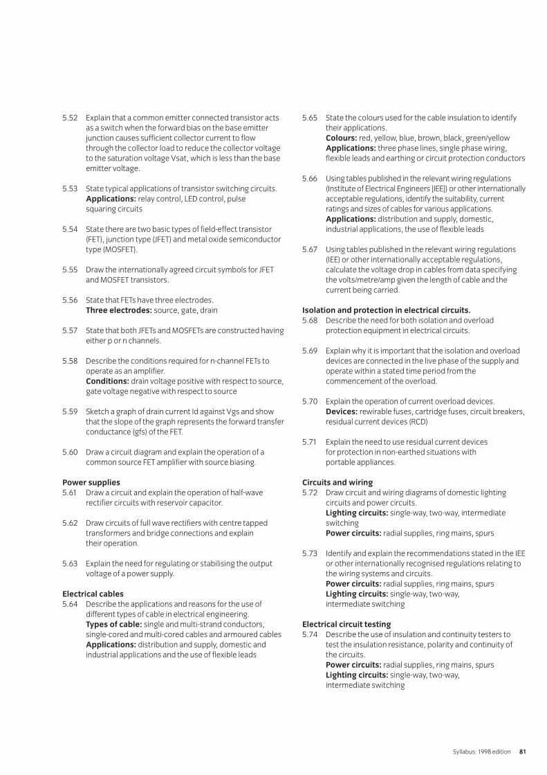
5.52 Explain that a common emitter connected transistor actsas a switch when the forward bias on the base emitterjunction causes sufficient collector current to flow through the collector load to reduce the collector voltageto the saturation voltage Vsat, which is less than the baseemitter voltage.
5.53 State typical applications of transistor switching circuits.Applications: relay control, LED control, pulse squaring circuits
5.54 State there are two basic types of field-effect transistor(FET), junction type (JFET) and metal oxide semiconductortype (MOSFET).
5.55 Draw the internationally agreed circuit symbols for JFETand MOSFET transistors.
5.56 State that FETs have three electrodes.Three electrodes: source, gate, drain
5.57 State that both JFETs and MOSFETs are constructed havingeither p or n channels.
5.58 Describe the conditions required for n-channel FETs tooperate as an amplifier.Conditions: drain voltage positive with respect to source,gate voltage negative with respect to source
5.59 Sketch a graph of drain current Id against Vgs and showthat the slope of the graph represents the forward transferconductance (gfs) of the FET.
5.60 Draw a circuit diagram and explain the operation of acommon source FET amplifier with source biasing.
Power supplies
5.61 Draw a circuit and explain the operation of half-waverectifier circuits with reservoir capacitor.
5.62 Draw circuits of full wave rectifiers with centre tappedtransformers and bridge connections and explain their operation.
5.63 Explain the need for regulating or stabilising the outputvoltage of a power supply.
Electrical cables
5.64 Describe the applications and reasons for the use ofdifferent types of cable in electrical engineering.Types of cable: single and multi-strand conductors,single-cored and multi-cored cables and armoured cablesApplications: distribution and supply, domestic andindustrial applications and the use of flexible leads
5.65 State the colours used for the cable insulation to identifytheir applications.Colours: red, yellow, blue, brown, black, green/yellowApplications: three phase lines, single phase wiring,flexible leads and earthing or circuit protection conductors
5.66 Using tables published in the relevant wiring regulations(Institute of Electrical Engineers [IEE]) or other internationallyacceptable regulations, identify the suitability, currentratings and sizes of cables for various applications.Applications: distribution and supply, domestic,industrial applications, the use of flexible leads
5.67 Using tables published in the relevant wiring regulations(IEE) or other internationally acceptable regulations,calculate the voltage drop in cables from data specifyingthe volts/metre/amp given the length of cable and thecurrent being carried.
Isolation and protection in electrical circuits.
5.68 Describe the need for both isolation and overloadprotection equipment in electrical circuits.
5.69 Explain why it is important that the isolation and overloaddevices are connected in the live phase of the supply andoperate within a stated time period from thecommencement of the overload.
5.70 Explain the operation of current overload devices.Devices: rewirable fuses, cartridge fuses, circuit breakers,residual current devices (RCD)
5.71 Explain the need to use residual current devices for protection in non-earthed situations with portable appliances.
Circuits and wiring
5.72 Draw circuit and wiring diagrams of domestic lightingcircuits and power circuits.Lighting circuits: single-way, two-way, intermediateswitchingPower circuits: radial supplies, ring mains, spurs
5.73 Identify and explain the recommendations stated in the IEEor other internationally recognised regulations relating tothe wiring systems and circuits.Power circuits: radial supplies, ring mains, spursLighting circuits: single-way, two-way, intermediate switching
Electrical circuit testing
5.74 Describe the use of insulation and continuity testers to test the insulation resistance, polarity and continuity of the circuits.Power circuits: radial supplies, ring mains, spursLighting circuits: single-way, two-way, intermediate switching
Syllabus: 1998 edition 81

5.75 Describe the use of earth loop testers to test theimpedance of the earthing protection system.
5.76 Identify from the regulations (IEE or other internationallyrecognised regulations) the limiting values for the testslisted in 5.74 and 5.75 above.
Electric motors
5.77 Describe the construction and explain the operation of different types of electric motor.Types of motors: dc commutator motor, dc brushless motor, three-phase induction motor, single-phase ac motor
5.78 State typical applications of the types of motors.Types of motors: dc commutator motor, dc brushless motor, three-phase induction motor, single-phase ac motor
Use of soldered connections
5.79 Identify the types of soldering iron, voltages and powerrating suitable for use in electrical work.
5.80 State the type and gauges of cored solder used in electricalwork and explain the purposes of the use of a suitable flux.
Integrated circuits
5.81 Explain that an integrated circuit is a silicon device withresistors, diodes and transistors formed in a single chip toprovide an active circuit device providing either linear orswitching/logic operations.
5.82 Explain that an operational amplifier (Op-Amp) is a highgain, differential amplifier in the form of a linear integratedcircuit with provision to control its voltage gain by meansof externally connected resistors.
5.83 Draw a circuit and explain the operation of an invertingamplifier based on an op-amp with negative feedback andshow that the voltage gain is controlled by the ratio of thefeedback to input resistors.
5.84 Draw a circuit and explain the operation of a non-invertingamplifier based on an op-amp with negative feedback andshow that the voltage gain is {1 + (the ratio of the feedback resistors)}.
5.85 Explain that digital integrated circuits consist of a siliconchip processed to form a number of logic circuitsinterconnect to provide a wide range of logic functions.
5.86 State there are two groups of logic integrated circuit,transistor-transistor logic (TTL) and complementary metaloxide semiconductors (CMOS).
5.87 Explain that CMOS circuits are based on insulated gatefield-effect devices (MOSFETs)and consume considerably less power than TTL types.
IVQ in Engineering 256582
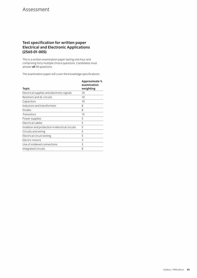
Test specification for written paperElectrical and Electronic Applications (2565-01-005)
This is a written examination paper lasting one hour andcomprising forty multiple choice questions. Candidates mustanswer all 40 questions.
The examination paper will cover the knowledge specifications:
Approximate %
examination
Topic weighting
Electrical supplies and electronic signals 10
Resistors and dc circuits 10
Capacitors 10
Inductors and transformers 8
Diodes 8
Transistors 15
Power supplies 5
Electrical cables 5
Isolation and protection in electrical circuits 5
Circuits and wiring 5
Electrical circuit testing 5
Electric motors 3
Use of soldered connections 3
Integrated circuits 8
Assessment
Syllabus: 1998 edition 83
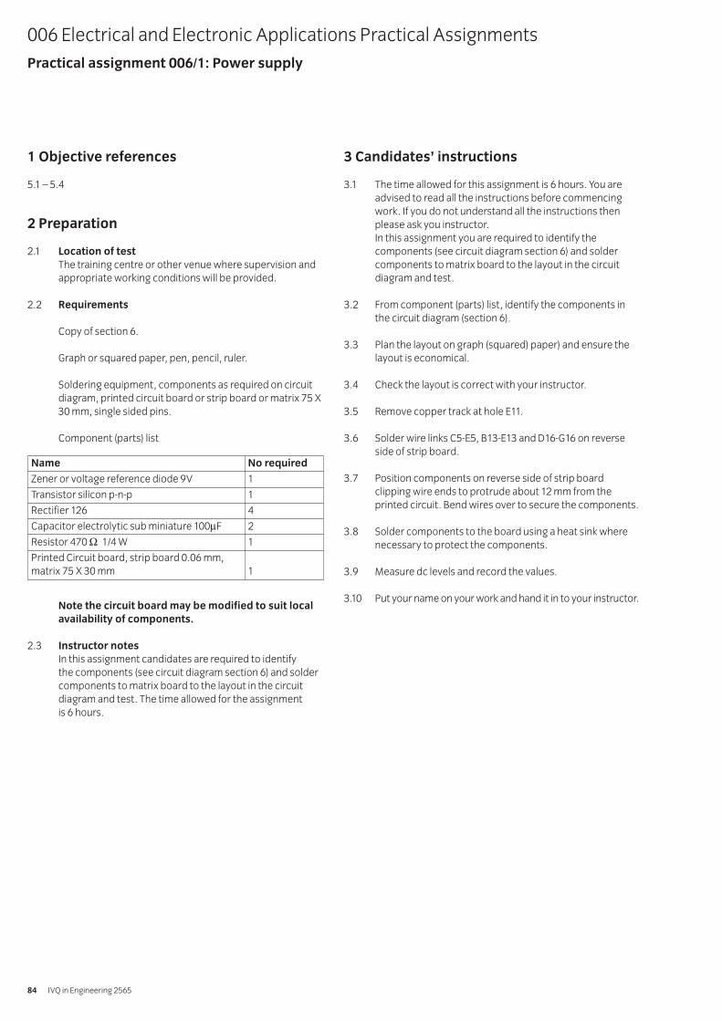
1 Objective references
5.1 – 5.4
2 Preparation
2.1 Location of test
The training centre or other venue where supervision andappropriate working conditions will be provided.
2.2 Requirements
Copy of section 6.
Graph or squared paper, pen, pencil, ruler.
Soldering equipment, components as required on circuitdiagram, printed circuit board or strip board or matrix 75 X30 mm, single sided pins.
Component (parts) list
Note the circuit board may be modified to suit local
availability of components.
2.3 Instructor notes
In this assignment candidates are required to identify the components (see circuit diagram section 6) and soldercomponents to matrix board to the layout in the circuitdiagram and test. The time allowed for the assignment is 6 hours.
3 Candidates’ instructions
3.1 The time allowed for this assignment is 6 hours. You areadvised to read all the instructions before commencingwork. If you do not understand all the instructions thenplease ask you instructor.In this assignment you are required to identify thecomponents (see circuit diagram section 6) and soldercomponents to matrix board to the layout in the circuitdiagram and test.
3.2 From component (parts) list, identify the components inthe circuit diagram (section 6).
3.3 Plan the layout on graph (squared) paper) and ensure thelayout is economical.
3.4 Check the layout is correct with your instructor.
3.5 Remove copper track at hole E11.
3.6 Solder wire links C5-E5, B13-E13 and D16-G16 on reverseside of strip board.
3.7 Position components on reverse side of strip boardclipping wire ends to protrude about 12 mm from theprinted circuit. Bend wires over to secure the components.
3.8 Solder components to the board using a heat sink wherenecessary to protect the components.
3.9 Measure dc levels and record the values.
3.10 Put your name on your work and hand it in to your instructor.
006 Electrical and Electronic Applications Practical AssignmentsPractical assignment 006/1: Power supply
IVQ in Engineering 256584
Name No required
Zener or voltage reference diode 9V 1
Transistor silicon p-n-p 1
Rectifier 126 4
Capacitor electrolytic sub miniature 100μF 2
Resistor 470 Ω 1/4 W 1
Printed Circuit board, strip board 0.06 mm,matrix 75 X 30 mm 1

4 Marking
4.1 Assignment completed in 6 hours. ( )
4.2 The components correctly listed. [ ]
4.3 The layout correctly and economically planned on graph (squared) paper. [ ]
4.4 The layout checked by the instructor. [ ]
4.5 Copper track at hole E11 removed. [ ]
4.6 Wire links C5-E5, B13-E13 and D16-G16 soldered on reverse side of strip board. [ ]
4.7 Components positioned on reverse side of strip board, wire ends clipped to protrude about 12 mm from the printed circuit, wires bent over to secure the components. [ ]
4.8 Components soldered to the board using a heat sink where necessary to protect the components. [ ]
4.9 dc levels measured and the values recorded. [ ]
4.10 Work handed in to your instructor. [ ]
5 Assignment completion
The candidate will have satisfactorily completed this assignmentif successful in all the items marked with [ ].
A period of seven days must elapse before an unsuccessfulcandidate may retake this assignment. An alternative circuitdesign should be used.
6 Assignment documentation
6.1 Component (parts) list
Syllabus: 1998 edition 85
Name No required
Zener or voltage reference diode 9V 1
Transistor silicon p-n-p 1
Rectifier 126 4
Capacitor electrolytic sub miniature 100μF 2
Resistor 470 Ω 1/4 W 1
Printed Circuit board, strip board 0.06 mm,matrix 75 X 30 mm 1
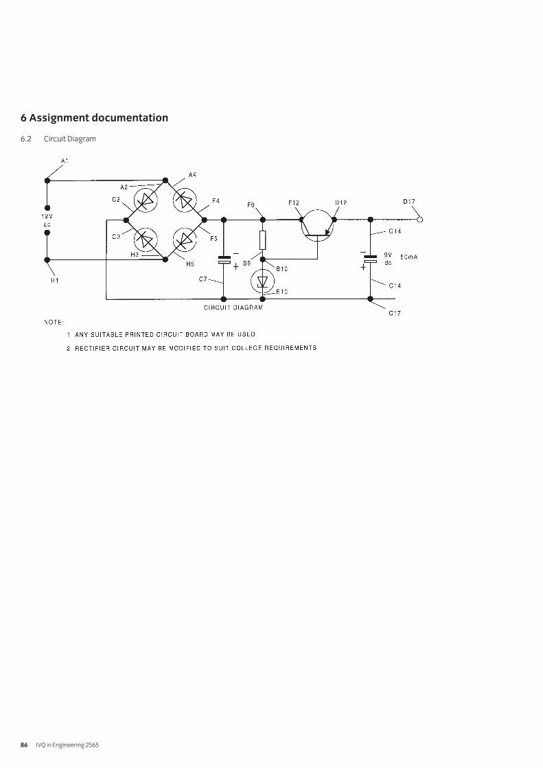
IVQ in Engineering 256586
6 Assignment documentation
6.2 Circuit Diagram
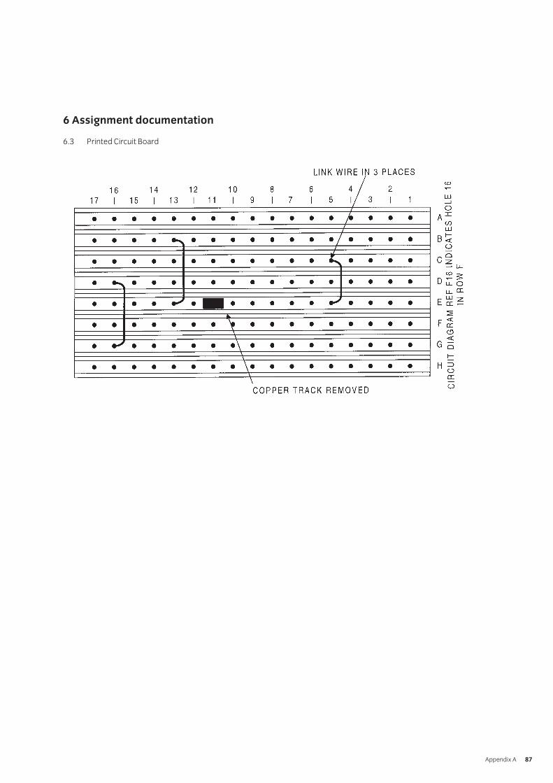
6 Assignment documentation
6.3 Printed Circuit Board
Appendix A 87
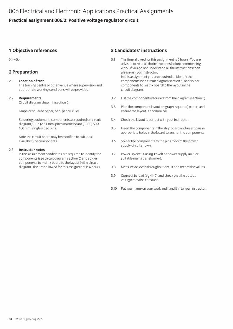
1 Objective references
5.1 – 5.4
2 Preparation
2.1 Location of test
The training centre or other venue where supervision andappropriate working conditions will be provided.
2.2 Requirements
Circuit diagram shown in section 6.
Graph or squared paper, pen, pencil, ruler.
Soldering equipment, components as required on circuitdiagram, 0.1in (2.54 mm) pitch matrix board (SRBP) 50 X100 mm, single sided pins.
Note the circuit board may be modified to suit localavailability of components.
2.3 Instructor notes
In this assignment candidates are required to identify thecomponents (see circuit diagram section 6) and soldercomponents to matrix board to the layout in the circuitdiagram. The time allowed for this assignment is 6 hours.
3 Candidates’ instructions
3.1 The time allowed for this assignment is 6 hours. You areadvised to read all the instructions before commencingwork. If you do not understand all the instructions thenplease ask you instructor.In this assignment you are required to identify thecomponents (see circuit diagram section 6) and soldercomponents to matrix board to the layout in the circuit diagram.
3.2 List the components required from the diagram (section 6).
3.3 Plan the component layout on graph (squared) paper) andensure the layout is economical.
3.4 Check the layout is correct with your instructor.
3.5 Insert the components in the strip board and insert pins inappropriate holes in the board to anchor the components.
3.6 Solder the components to the pins to form the powersupply circuit shown.
3.7 Power up circuit using 12 volt ac power supply unit (orsuitable mains transformer).
3.8 Measure dc levels throughout circuit and record the values.
3.9 Connect to load (eg 4 K 7) and check that the outputvoltage remains constant.
3.10 Put your name on your work and hand it in to your instructor.
006 Electrical and Electronic Applications Practical AssignmentsPractical assignment 006/2: Positive voltage regulator circuit
IVQ in Engineering 256588
4 Marking
4.1 Assignment completed in 6 hours. ( )
4.2 The components correctly listed. [ ]
4.3 The layout correctly and economically planned on graph (squared) paper. [ ]
4.4 The layout checked by the instructor. [ ]
4.5 The components inserted in the strip board and pinsinserted in appropriate holes in the board to anchor the components. [ ]
4.6 The components soldered to the pins to form the amplifier circuit shown. [ ]
4.7 Circuit powered up using 12 volt ac power supply unit (or mains transformer). [ ]
4.8 dc levels measured throughout circuit and the values recorded. [ ]
4.9 Connected to load and output voltage remained constant. [ ]
4.10 Work handed in to your instructor. [ ]
5 Assignment completion
The candidate will have satisfactorily completed this assignmentif successful in all the items marked with [ ].
A period of seven days must elapse before an unsuccessfulcandidate may retake this assignment. An alternative circuitdesign should be used.
Appendix A Practical Assignments 89
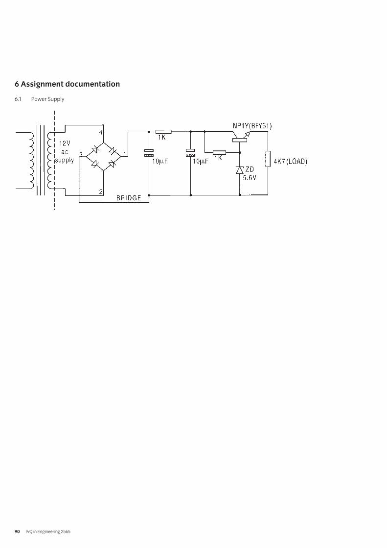
IVQ in Engineering 256590
6 Assignment documentation
6.1 Power Supply
1 Objective references
5.1 – 5.5
2 Preparation
2.1 Location of test
The training centre or other venue where supervision andappropriate working conditions will be provided.
2.2 Requirements
Circuit diagram shown in section 6.
Graph or squared paper, pen, pencil, ruler.
Soldering equipment, components as required on circuitdiagram, 0.1in (2.54 mm) pitch matrixboard (SRBP) 50 X 100 mm, single sided pins.
Note the circuit board may be modified to suit localavailability of components.
2.3 Instructor notes
In this assignment candidates are required to identify thecomponents (see circuit diagram section 6) and solder thecomponents to the matrix board to the layout in the circuitdiagram. Time allowed for this assignment 6 hours.
3 Candidates’ instructions
3.1 The time allowed for this assignment is 6 hours. You areadvised to read all the instructions before commencingwork. If you do not understand all the instructions thenplease ask you instructor.In this assignment you are required to identify thecomponents (see circuit diagram section 6), soldercomponents to matrix board to the layout in the circuit diagram.
3.2 List the components required from the diagram (section 6).
3.3 Plan the layout on graph (squared) paper and ensure thelayout is economical.
3.4 Check the layout is correct with your instructor.
3.5 Insert the components in the strip board and insert pins inappropriate holes in the board to anchor the components.
3.6 Solder the components to the pins to form the amplifiercircuit shown.
3.7 Power up circuit using 9 volt power supply unit (or battery).
3.8 Check dc levels throughout circuit and record the values.
3.9 Input 1 kHz signal from signal generator and display inputand output on an oscilloscope. Adjust input amplitude toavoid any distortion.
3.10 Draw the input signal and the output signal and measurethe amplitudes.
3.11 Calculate the voltage gain of the amplifier from the resultsobtained in 3.10.
3.12 Increase the input amplitude to a maximum value withoutcausing significant distortion and record the value.
3.13 Put your name on your work and hand it in to your instructor.
006 Electrical and Electronic Applications Practical AssignmentsPractical assignment 006/3: Amplifier
Syllabus: 1998 edition 91
4 Marking
4.1 Assignment completed in 6 hours. ( )
4.2 The components correctly listed. [ ]
4.3 The layout correctly and economically planned on graph (squared) paper. [ ]
4.4 The layout checked by the instructor. [ ]
4.5 The components inserted in the strip board and pinsinserted in appropriate holes in the board to anchor the components. [ ]
4.6 The components soldered to the pins to form the amplifier circuit shown. [ ]
4.7 Circuit powered up using 9 volt power supply unit (or battery). [ ]
4.8 dc levels checked throughout circuit and the values recorded. [ ]
4.9 Input 1 KHz signal input from signal generator and input and output signal displayed on an oscilloscope. Input amplitude adjusted to avoid any distortion. [ ]
4.10 The input signal and the output signal drawn and theamplitudes measured. [ ]
4.11 The voltage gain of the amplifier calculated from theresults obtained in 4.10. [ ]
4.12 The input amplitude increased to a maximum value without causing significant distortion and the value recorded. [ ]
4.13 Work handed in to the instructor. [ ]
5 Assignment completion
The candidate will have satisfactorily completed this assignmentif successful in all the items marked with [ ].
A period of seven days must elapse before an unsuccessfulcandidate may retake this assignment. An alternative circuitdesign should be used.
IVQ in Engineering 256592
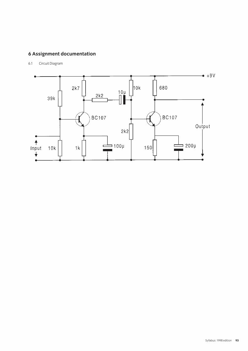
6 Assignment documentation
6.1 Circuit Diagram
Syllabus: 1998 edition 93
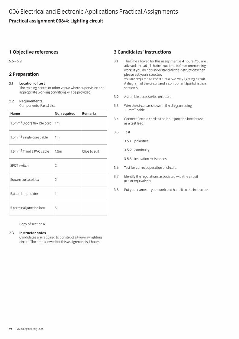
1 Objective references
5.6 – 5.9
2 Preparation
2.1 Location of test
The training centre or other venue where supervision andappropriate working conditions will be provided.
2.2 Requirements
Components (Parts) List
Copy of section 6.
2.3 Instructor notes
Candidates are required to construct a two-way lightingcircuit. The time allowed for this assignment is 4 hours.
3 Candidates’ instructions
3.1 The time allowed for this assignment is 4 hours. You areadvised to read all the instructions before commencingwork. If you do not understand all the instructions thenplease ask you instructor.You are required to construct a two-way lighting circuit. A diagram of the circuit and a component (parts) list is insection 6.
3.2 Assemble accessories on board.
3.3 Wire the circuit as shown in the diagram using 1.5mm2 cable.
3.4 Connect flexible cord to the input junction box for use as a test lead.
3.5 Test
3.5.1 polarities
3.5.2 continuity
3.5.3 insulation resistances.
3.6 Test for correct operation of circuit.
3.7 Identify the regulations associated with the circuit (IEE or equivalent).
3.8 Put your name on your work and hand it to the instructor.
006 Electrical and Electronic Applications Practical AssignmentsPractical assignment 006/4: Lighting circuit
IVQ in Engineering 256594
Name No. required Remarks
1.5mm2 3-core flexible cord 1m
1.5mm2 single core cable 1m
1.5mm2 T and E PVC cable 1.5m Clips to suit
SPDT switch 2
Square surface box 2
Batten lampholder 1
5-terminal junction box 3
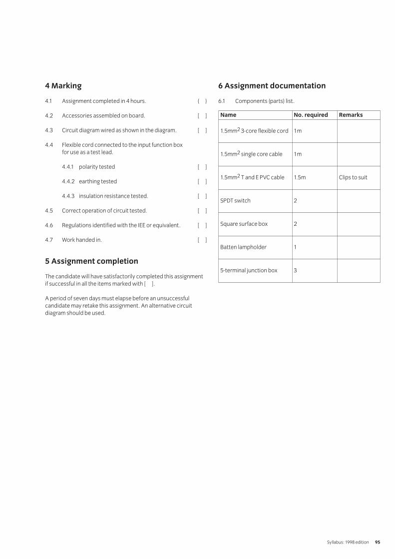
4 Marking
4.1 Assignment completed in 4 hours. ( )
4.2 Accessories assembled on board. [ ]
4.3 Circuit diagram wired as shown in the diagram. [ ]
4.4 Flexible cord connected to the input function box for use as a test lead.
4.4.1 polarity tested [ ]
4.4.2 earthing tested [ ]
4.4.3 insulation resistance tested. [ ]
4.5 Correct operation of circuit tested. [ ]
4.6 Regulations identified with the IEE or equivalent. [ ]
4.7 Work handed in. [ ]
5 Assignment completion
The candidate will have satisfactorily completed this assignmentif successful in all the items marked with [ ].
A period of seven days must elapse before an unsuccessfulcandidate may retake this assignment. An alternative circuitdiagram should be used.
6 Assignment documentation
6.1 Components (parts) list.
Syllabus: 1998 edition 95
Name No. required Remarks
1.5mm2 3-core flexible cord 1m
1.5mm2 single core cable 1m
1.5mm2 T and E PVC cable 1.5m Clips to suit
SPDT switch 2
Square surface box 2
Batten lampholder 1
5-terminal junction box 3
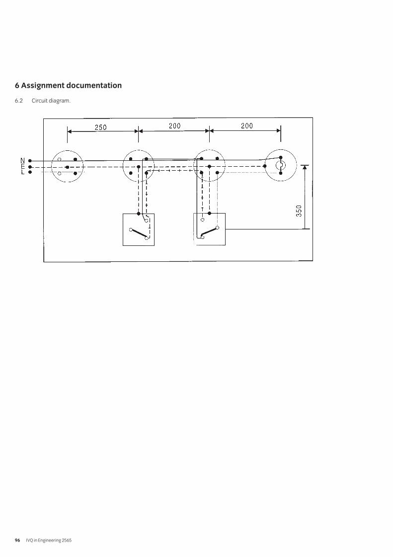
6 Assignment documentation
6.2 Circuit diagram.
IVQ in Engineering 256596
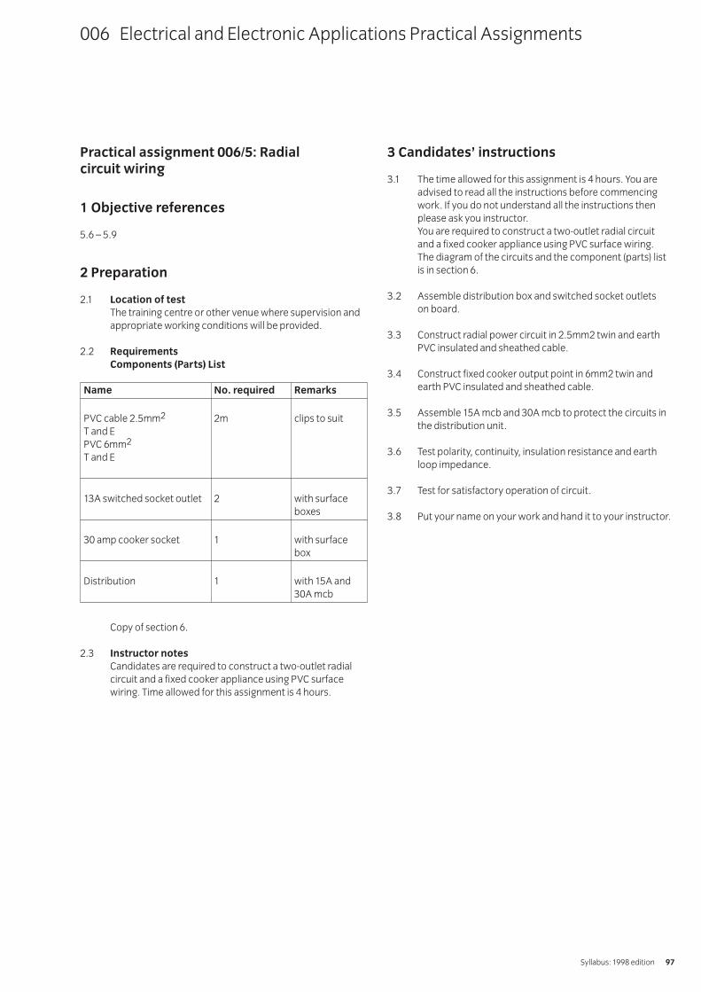
Practical assignment 006/5: Radial circuit wiring
1 Objective references
5.6 – 5.9
2 Preparation
2.1 Location of test
The training centre or other venue where supervision andappropriate working conditions will be provided.
2.2 Requirements
Components (Parts) List
Copy of section 6.
2.3 Instructor notes
Candidates are required to construct a two-outlet radialcircuit and a fixed cooker appliance using PVC surfacewiring. Time allowed for this assignment is 4 hours.
3 Candidates’ instructions
3.1 The time allowed for this assignment is 4 hours. You areadvised to read all the instructions before commencingwork. If you do not understand all the instructions thenplease ask you instructor.You are required to construct a two-outlet radial circuit and a fixed cooker appliance using PVC surface wiring. The diagram of the circuits and the component (parts) listis in section 6.
3.2 Assemble distribution box and switched socket outlets on board.
3.3 Construct radial power circuit in 2.5mm2 twin and earthPVC insulated and sheathed cable.
3.4 Construct fixed cooker output point in 6mm2 twin andearth PVC insulated and sheathed cable.
3.5 Assemble 15A mcb and 30A mcb to protect the circuits inthe distribution unit.
3.6 Test polarity, continuity, insulation resistance and earthloop impedance.
3.7 Test for satisfactory operation of circuit.
3.8 Put your name on your work and hand it to your instructor.
006 Electrical and Electronic Applications Practical Assignments
Syllabus: 1998 edition 97
Name No. required Remarks
PVC cable 2.5mm2 2m clips to suitT and EPVC 6mm2
T and E
13A switched socket outlet 2 with surfaceboxes
30 amp cooker socket 1 with surfacebox
Distribution 1 with 15A and30A mcb
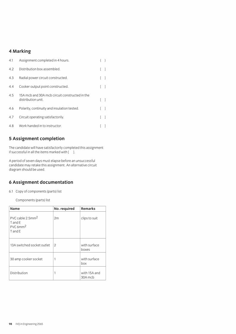
4 Marking
4.1 Assignment completed in 4 hours. ( )
4.2 Distribution box assembled. [ ]
4.3 Radial power circuit constructed. [ ]
4.4 Cooker output point constructed. [ ]
4.5 15A mcb and 30A mcb circuit constructed in thedistribution unit. [ ]
4.6 Polarity, continuity and insulation tested. [ ]
4.7 Circuit operating satisfactorily. [ ]
4.8 Work handed in to instructor. [ ]
5 Assignment completion
The candidate will have satisfactorily completed this assignmentif successful in all the items marked with [ ].
A period of seven days must elapse before an unsuccessfulcandidate may retake this assignment. An alternative circuitdiagram should be used.
6 Assignment documentation
6.1 Copy of components (parts) list
Components (parts) list
IVQ in Engineering 256598
Name No. required Remarks
PVC cable 2.5mm2 2m clips to suitT and EPVC 6mm2
T and E
13A switched socket outlet 2 with surfaceboxes
30 amp cooker socket 1 with surfacebox
Distribution 1 with 15A and30A mcb
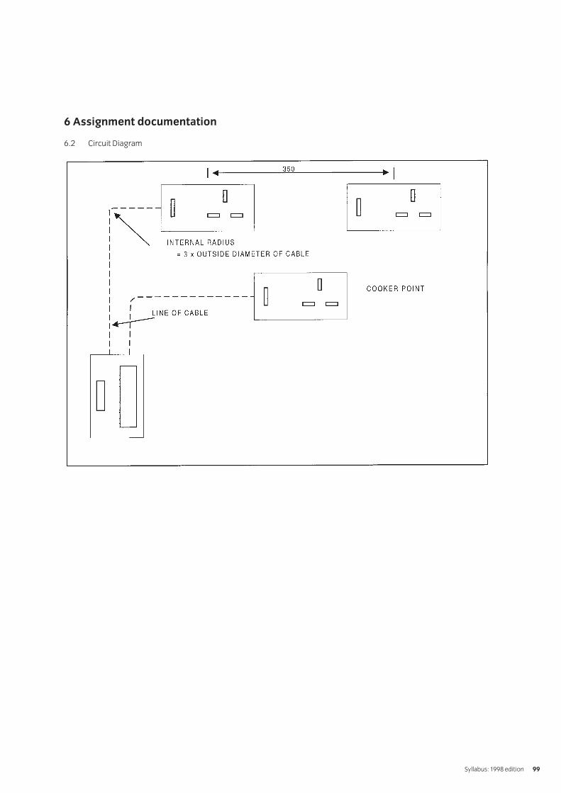
6 Assignment documentation
6.2 Circuit Diagram
Syllabus: 1998 edition 99

[ This page is intentionally blank ]

Introduction
The aim of this module is to provide the entry level ofmathematics required by candidates wishing to take theassessments for the Technician Certificate Awards in Engineering.
Knowledge requirements
Instructors must ensure that candidates are able to:
Numeracy
1 Perform calculations involving the four operations ofaddition, subtraction, multiplication and division applied to whole and decimal numbers.
2 Perform calculations involving the four arithmeticoperations applied to positive and negative numbers,using the rules relating to directed numbers.
3 Perform calculations to convert decimal fractions to apercentage and a percentage to a fraction.
4 Perform calculations to express one quantity as apercentage of another.
5 Perform calculations to divide various amounts into given ratios.
6 Perform calculations involving two quantities in directproportion to each other.
7 Perform calculations involving two quantities in inverseproportion to each other.
8 Deduce estimated solutions to arithmetic calculations,expressing the results to both a given number of significantfigures and to a given number of decimal places.
9 Express denary numbers in binary form and binarynumbers in denary form.
10 Define the terms base, index, power, reciprocal and square root.
11 Perform calculations applying the rulesam x an = a(m+n); am/an = a(m-n); (am)n = amn where m andn are positive indices; m and n are negative indices; m andn are fractional indices.
Algebra
12 Represent quantities by symbols and translate phrasesinvolving quantities into algebraic expressions.
13 Simplify algebraic expressions involving symbols andnumbers using a range of methods.Methods: collect like terms using addition andsubtraction; multiply and divide using the rules for directednumbers where applicable; remove brackets whereapplicable; apply the priority order precedence rulesrelating to arithmetic operations
14 Factorise expressions by extracting common factors, eg ax + ay = a(x + y) and grouping, ax – ay + bx – by = (a + b)(x – y)
15 Construct and solve simple linear equations usingappropriate data.
16 Evaluate formulae by substituting appropriate data.
Geometry
17 Identify a range of plane figures.Plane figures: square, rectangle, triangle and circle
18 Calculate the perimeter and area of the plane figures.Plane figures: square, rectangle, triangle and circle
19 Construct triangles from given information.Given information: the lengths of three sides, the lengthsof two sides and the magnitude of the included angle, thelength of one side and the magnitudes of two angles
20 Identify the Theorem of Pythagoras and apply it todetermine the length of the unknown side of a right-angledtriangle given the length of the other two sides.
Graphs
21 Identify the point of origin for horizontal and vertical axesincluding positive and negative co-ordinates.
22 Determine suitable scales to be applied to the axes toenable given data to be plotted.
23 Plot graphs from given data.
24 Read values of y for given values of x and values of x forgiven values of y from a graph and interpolate intermediatevalues between points.
Appendix AEntry level mathematics
Appendix A 101

[ This page is intentionally blank ]
Two assessment methods are used in the 2565 Technician Awards in Engineering programme – written questions andpractical assignments.
Practical assignments
Each unit or component in the Certificate level of this programmehas a related practical assignment or assignments. Theseassignments may call on skills covered in other sections butreference is only made to the objectives covered by the markingcriteria. Wherever relevant the option is given for you to use localnames, local currencies, alternative measurements and papersizes, or to design an alternative assessment. Where this option istaken the assignment must be of a comparable standard toensure consistency between centres using this programme. Theassignment must be documented and available for the visitingverifier. ALL assignments must be successfully completed.
The assignments may be administered at any time convenient tothe instructor and to the candidate.
The practical assignments in this publication are intended to be photocopied.
Instructor notes
It is essential that you read these before attempting to administerthe practical assignment. Practical assignments usually requireyou to prepare material for the assignment.
Candidate instructions
Make sure every candidate has a copy of these before beginningthe practical assignment.
Marking
The marking is based on performance criteria or outcomesrelated to the practical assignment, to which the answer willalways be either ‘yes – the candidate achieved this’ or ‘no – thecandidate did not achieve this’. Credit is given for thoseperformance objectives for which the answer is ‘yes – thecandidate achieved this’.
Supervision
All assignments require supervision and you must make sure thatthe results reflect only the individual candidate’s own work. Youmust keep all assessment documentation and material in a file foreach candidate until the results have been agreed by the visitingverifier and until confirmation of result has been received fromCity & Guilds.
Records, results and certification
Successful completion of the related practical assignments foreach unit needs to be recorded and then sent to City & Guilds. Wesuggest that you keep a record of each individual’s achievementswhich may then be transferred to the entry forms. A model isgiven at the end of this section but you may use any form ofrecord keeping that is convenient and accessible.
In order to gain certification, results for successfully completedpractical assignments must be sent to City & Guilds. Results forpractical assignments are entered onto Form S which is thencountersigned by the visiting verifier and sent to us.
An advantage of this programme is that candidates whosuccessfully complete the practical assignments for a single unitmay, if they wish, claim a Certificate of Unit Credit. This may bebeneficial for those candidates who only wish to complete part ofthis programme. Send these claims to us at any time provided thevisiting verifier has countersigned the Form S.
Candidates wishing to gain the full award (Certificate, Diploma or Advanced Diploma) must successfully complete all the relevant practical assignments. We recommend that theirpractical results are sent at the time of, or shortly before the date of the written examinations.
Visiting verifier
The operation of this programme requires the appointment of avisiting verifier. The visiting verifier must countersign the
results of the practical assignments on Form S. The visitingverifier should also be able to inspect records and candidates’work to verify the results before submission.
Appendix BPractical assignments
Appendix B 103
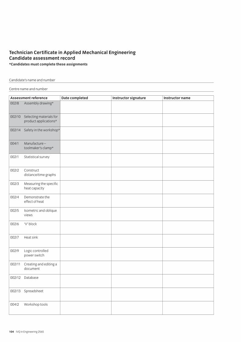
Technician Certificate in Applied Mechanical EngineeringCandidate assessment record*Candidates must complete these assignments
IVQ in Engineering 2565104
Candidate’s name and number
Centre name and number
Assessment reference Date completed Instructor signature Instructor name
002/8 Assembly drawing*
002/10 Selecting materials for product applications*
002/14 Safety in the workshop*
004/1 Manufacture – toolmaker’s clamp*
002/1 Statistical survey
002/2 Construct distance/time graphs
002/3 Measuring the specific heat capacity
002/4 Demonstrate the effect of heat
002/5 Isometric and oblique views
002/6 ‘V’ block
002/7 Heat sink
002/9 Logic controlled power switch
002/11 Creating and editing a document
002/12 Database
002/13 Spreadsheet
004/2 Workshop tools
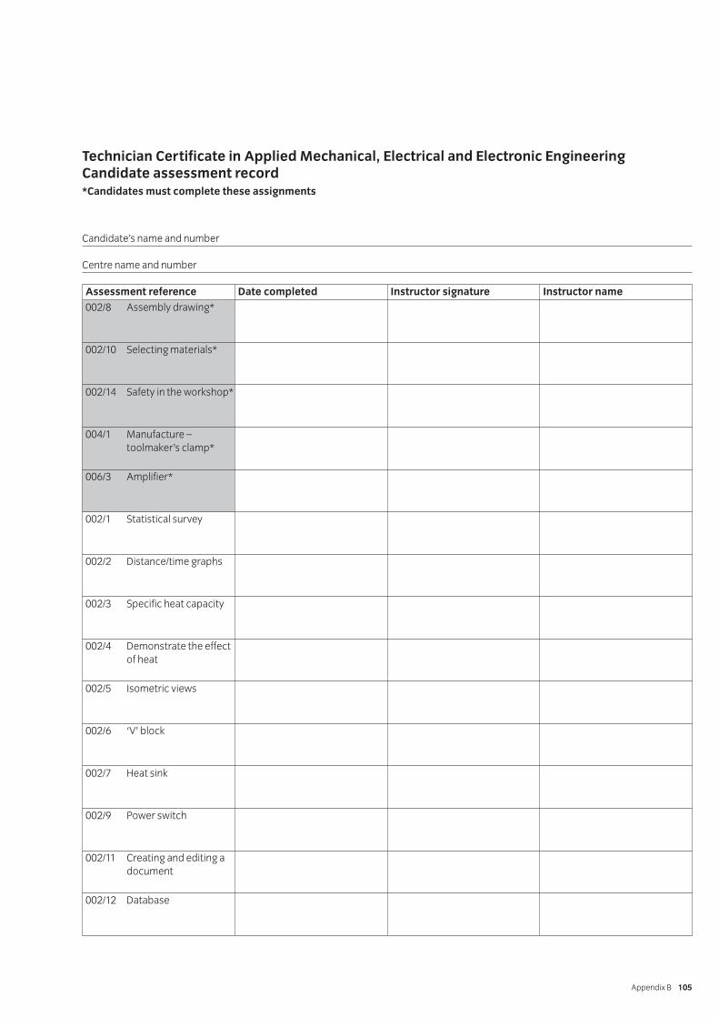
Technician Certificate in Applied Mechanical, Electrical and Electronic EngineeringCandidate assessment record*Candidates must complete these assignments
Appendix B 105
Candidate’s name and number
Centre name and number
Assessment reference Date completed Instructor signature Instructor name
002/8 Assembly drawing*
002/10 Selecting materials*
002/14 Safety in the workshop*
004/1 Manufacture – toolmaker’s clamp*
006/3 Amplifier*
002/1 Statistical survey
002/2 Distance/time graphs
002/3 Specific heat capacity
002/4 Demonstrate the effect of heat
002/5 Isometric views
002/6 ‘V’ block
002/7 Heat sink
002/9 Power switch
002/11 Creating and editing a document
002/12 Database

IVQ in Engineering 2565106
Assessment reference Date completed Instructor signature Instructor name
002/13 Spreadsheet
004/2 Workshop tools
006/1 Power supply
006/2 Regulator circuit
006/4 Lighting circuit
006/5 Radial circuit
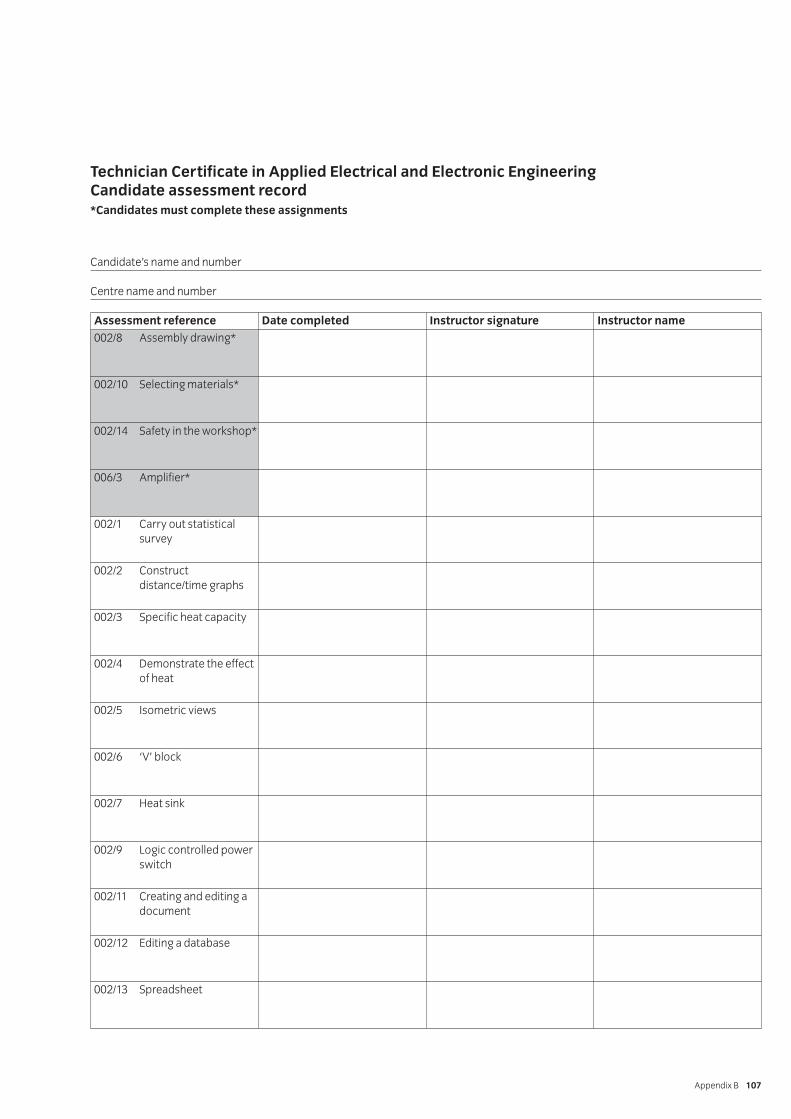
Technician Certificate in Applied Electrical and Electronic EngineeringCandidate assessment record*Candidates must complete these assignments
Appendix B 107
Candidate’s name and number
Centre name and number
Assessment reference Date completed Instructor signature Instructor name
002/8 Assembly drawing*
002/10 Selecting materials*
002/14 Safety in the workshop*
006/3 Amplifier*
002/1 Carry out statisticalsurvey
002/2 Construct distance/time graphs
002/3 Specific heat capacity
002/4 Demonstrate the effect of heat
002/5 Isometric views
002/6 ‘V’ block
002/7 Heat sink
002/9 Logic controlled power switch
002/11 Creating and editing a document
002/12 Editing a database
002/13 Spreadsheet

IVQ in Engineering 2565108
Assessment reference Date completed Instructor signature Instructor name
006/1 Power supply
006/2 Regulator circuit
006/4 Lighting circuit
006/5 Radial circuit wiring


Published by City & Guilds
1 Giltspur Street
London
EC1A 9DD
T +44 (0)20 7294 2850
F +44 (0)20 7294 2413
www.cityandguilds.com
City & Guilds is a registered
charity established to promote
education and training
SP-50-2565