Embed Size (px)
Citation preview

Integrated Vehicle Tire Pressure Monitoring
IVTM Installation Manual
2nd edition
Copyright WABCO 2006
Vehicle Control SystemsAn American Standard Company
The right of amendment is reservedVersion 002/06.06(us)
8152201143 815 220 114 3

Service Notes
About This ManualThis manual contains installation instructions forWABCO's Integrated Vehicle Tire Pressure Monitor-ing System for trucks, tractors, trailers and buses.
Before You Begin1. Read and understand all instructions and proce-
dures before you begin to service components.
2. Read and observe all Warning and Caution hazard alert messages in this publication. Theyprovide information that can help prevent seri-ous personal injury, damage to components, orboth.
3. Follow your company's maintenance and ser-vice, installation, and diagnostics guidelines.
Hazard Alert Messages and Symbols
How to Obtain Additional Information
On the WebVisit www.wabco-auto.com and open INFORM.Search for IVTM in the Index.
Note: Wheel modules and ECU's are not serviceable.Tampering with factory fasteners or seals voids thewarranty.
FCC Notice:This device consists of wheel module960 730 XXX X (SA4-WM730) and Electronic Con-trol Unit 446 220 XXX X (SA4-ECU220). This devicecomplies with Part 15 of the FCC Rules. Operationis subject to the following two conditions: (1) this de-vice may not cause harmful interference, and (2) thisdevice must accept any interference received, in-cluding interference that may cause undesired oper-ation. Changes or modifications not expresslyapproved by the party responsible for the compli-ance could void the user's authority to operate theequipment.
RF (Radio Frequency) products such as the IVTMsystem utilize RF technology to transmit a signal be-tween the wheel module sensor and the ECU (elec-tronic control unit). All RF signals are subjected tointerference from many types of signals and prod-ucts, which can cause reception issues that, effectthe operation of the IVTM system. As with cellphones and other types of electronics using RF sig-nals, signal interruption can occur and cause a lostsignal transmission. The IVTM system has beentested and designed to work optimally to overcomethe interference that can block signals, as with anyRF products, signal guarantee can not be made.
A Warning alerts you to an instruc-tion or procedure that you must fol-low exactly to avoid seriouspersonal injury and damage tocomponents.
A Caution alerts you to an instruc-tion or procedure that you must fol-low exactly to avoid damage tocomponents.
WARNING
CAUTION

3
Section 1: Introduction and system overview Page 4
Section 2: Installation overview Page 5
Section 3: Wheels - Installation of hoses and wheel modules Page 6
Section 4: Undercarriage - Installation of the ECU's and wiring of the ECU's Page 8Trailer Page 8Tractor Page 10
Section 5: Vehicle cab - Wiring, display placement and power supply Page 11
Section 6: Operating instructions Page 13
Section 7: ECU programming Page 13
Appendix Page 16Figure A1 Record wheel module ID numbers Page 17Figure A2 / A3 Wiring harness and connector pin assignment Page 17Figure A4 Diagnostic cable 449 674 306 0 Page 17
Table of Contents

4
IVTM System Overview
The IVTM system uses RF (radio frequency433 MHz) to broadcast individual tire pressure tothe ECU (electronic control unit). The ECU evalu-ates the pressure via an algorithm then forwards in-
formation via a cable to the display for driver actionif necessary. The data provides audible and visualnotification and system status. Transmission viaSAE J1939 is also available.
IntroductionIVTM1.
display wheel module* trailer wiring tractor wiring
ECU
ECU bracket
balance plate*
inner wheel hose* outer wheel hose* steer wheel hose*
Pre-Installation checklist• Confirm the vehicle uses a hub-piloted mount-
ing system.
• The IVTM shipment will include a list that indi-cates a breakdown of parts for your installation.
• PC running Windows 95 or higher, 30 MB freehard disk space, color display 1024 x 768 min.with one free serial port for ECU programming.
• This manual is divided into three sections. This will allow multiple technicians to completethe installation if desired.
• A vehicle wiring diagram or knowledge of thevehicle electrical system will be helpful to com-plete the installation.
• On dual wheels the valve stems must bedirectly opposing each other for proper installa-tion of the wheel modules.
Fig. 1.1: Components * illustrations vary by application

5
IVTM Installation Overview
Installation proceduresThe system can be broken down into three groups(see below). If desired the installation can be com-pleted by three technicians. Prior to beginning theinstallation or modification to the vehicle, determinethe locations for the ECU, display and wiring path.
It is best to start with the wheel modules. Maintain-ing a list of the wheel module numbers and locationon the vehicle is required for proper ECU program-ming (see form in appendix).
Section 3: Wheels - Installation of hoses and wheel modules (technician “A“)
Section 4: Undercarriage - Installation of the ECU and wiring of the ECU (technician “B“)
Section 5: Vehicle cab - Wiring the display, power supply (technician “C“)
Section 6: ECU programming (technician “C“)
Make sure the vehicle is securedand the wheels are blocked.
To prevent serious eye injury, al-ways wear eye protection when youperform vehicle maintenance or ser-vice.
Wear required safety shoes during installation,follow all safety rules and regulations that applyfor your shop and location.
Before moving the vehicle into the shop, observeall safety precautions. Park the vehicle on a levelnon-slip surface. Block the wheels to prevent thevehicle from moving in any direction.
Do not weld, drill, cut or modify the vehicle chas-sis if prohibited by the vehicle manufacturer.
Consult and follow all wheel manufacturers spec-ifications, including but not limited to the torquetightening of the wheel lug nuts.
WARNING
CAUTION
Installation IVTM 2.

6
Wheels - Installation of hoses and wheel modules
1. For tandem / dual wheels, connect the longerof the hoses (#960 901 054 2) to the wheelmodule and then to the valve stem. Push thehose into wheel module until fully seated andturn to lock. Mount the wheel module to thewheel with lug nuts and hand tighten the hoseto the inner tire without twisting or binding thehose. A good seal is required at each valvestem. Check each connection by sprayingsoapy water on each connection to check forleakage.
2. Repeat process for the outer wheel, install theshorter hose (#960 901 053 2) to the wheelmodule and then to the valve stem. On dualwheels locate wheel modules directly acrossfrom each other for balancing purposes.
3. Repeat for front steer wheels, install the short-est hose with a straight end (#960 901 052 2)to the wheel module and then to the valvestem.
4. On steer wheels, it will be necessary to install abalancing plate (#960 730 832 4) directly oppo-site of the wheel module for balancing pur-poses.
5. Where a wide base tire is fitted, a balance platemay be required opposite the wheel module.An optional wide base hose is available part #960 730 052 4.
6. Record each wheel module I.D. number foreach location. This will be used later for ECUprogramming (see form in appendix).
7. The wheel modules should be located directlyopposing each other, except on steer wheelswhere a balancing plate must be installed.
Center the wheel module betweenboth wheel studs. When re-install-ing and torque tightening the wheellugs, use Caution not to damagethe housing of the wheel module.
CAUTION
Wheels - InstallationIVTM3.
Hose #960 901 054 2
Hose #960 901 053 2
Hose #960 901 052 2
Hose #960 730 052 4
Balance Plate #960 730 832 4
7
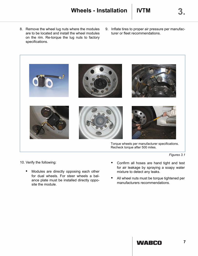
8. Remove the wheel lug nuts where the modulesare to be located and install the wheel moduleson the rim. Re-torque the lug nuts to factoryspecifications.
9. Inflate tires to proper air pressure per manufac-turer or fleet recommendations.
Wheels - Installation IVTM 3.
Torque wheels per manufacturer specifications.
Recheck torque after 500 miles.
10. Verify the following:
• Modules are directly opposing each otherfor dual wheels. For steer wheels a bal-ance plate must be installed directly oppo-site the module.
• Confirm all hoses are hand tight and testfor air leakage by spraying a soapy watermixture to detect any leaks.
• All wheel nuts must be torque tightened permanufacturers recommendations.
Figures 3.1

8
Installation of the ECU and wiring of the ECU
Trailer Installation1. The trailer ECU (# 446 220 013 0) should be
located within 1/3 to 1/2 to the front of thetrailer and must be clear of metal brackets andobjects. The ECU should be parallel to mainframe, in line with drive direction. This is nec-essary to provide RF transmission to the trac-tor ECU. Install as indicated in figure 4.2, 4.3and 4.4.
2. Determine where to install the ECU andbracket on the trailer. Modifications to thetrailer may be necessary to install the providedbracket. The ECU must be installed with thehousing connection (mounted) facing as indi-cated in figure 4.4.
3. A bracket may need to be fabricated to supportthe supplied bracket. This can be achievedwith a "C" channel section as illustrated in fig-ure 4.7.
4. The ECU must be mounted with bracket(# 960 901 050 4). The housing of the ECUmust have clearance on the front and back sur-
faces for proper reception of the signal fromthe wheel modules as indicated in figure 4.4.
5. After installation of the ECU to the trailer frame,it will be necessary to wire the ECU into thetrailers wiring circuit. The provided wiring maybe routed along the same path as the currenttrailer wiring. The trailer ECU wiring(# 449 674 306 0) must be secured to thetrailer ECU connection. This is a simple twiston design. Make sure the connection is tight,the connector will click when it has fully lockedinto place.
6. The opposing end of the trailer wiring must bewired into the following circuits:
a. White wire to Brake lightb. Brown wire to Groundc. Red wire to 12 volt trailer feed (add in
line 5 amp fuse - not provided)d. Locate the diagnostic (blue) connector
so it can be easily accessed on thetrailer for future programming and di-agnostic functions (see fig. 4.2)
7. All wiring including any excess should be plas-tic wire tied to the vehicle frame in a secureposition. If the wiring is excessively long itshould be wire tied to the frame, not cut. Donot wrap wire in circular pattern whensecuring to the frame!
Vehicle’s safety can be affected.Comply with all safety and vehiclemanufacturer guidelines as to mod-ification of the frame rail or its com-ponents.
WARNING
UndercarriageIVTM4.
ECU
Diagnosis
Brown: Ground Red: +12V
White: Brake light
5A (fuse notprovided)
Figure 4.1

9
Undercarriage IVTM 4.
Diagnostic socket
Electronic Control Unit (ECU)
+12V, Ground, Brake Light Figure 4.2
Figure 4.3
Figure 4.4
Common Trailer Configuration
1/2
2/3
Note:
Wheel modulesare alwaysmounted on theoutside wheels.
1/2 - 2/3
1/2 - 2/3
to1/2
2/3
Note:
Note:
2“ 2“The ECU may not be obstructed by any objects in order to provide clear RFsignal reception.
The ECU must have two inches of clearance asindicated.
10
Installation of the ECU's and wiring of the ECU's (Cont)
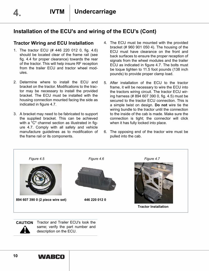
Tractor Wiring and ECU Installation1. The tractor ECU (# 446 220 012 0, fig. 4.6)
should be located clear of the frame rail (seefig. 4.4 for proper clearance) towards the rearof the tractor. This will help insure RF receptionfrom the trailer ECU and tractor wheel mod-ules.
2. Determine where to install the ECU andbracket on the tractor. Modifications to the trac-tor may be necessary to install the providedbracket. The ECU must be installed with thehousing connection mounted facing the side asindicated in figure 4.7.
3. A bracket may need to be fabricated to supportthe supplied bracket. This can be achievedwith a "C" channel section as illustrated in fig-ure 4.7. Comply with all safety and vehiclemanufacture guidelines as to modification ofthe frame rail or its components.
4. The ECU must be mounted with the providedbracket (# 960 901 050 4). The housing of theECU must have clearance on the front andback surfaces to ensure the proper reception ofsignals from the wheel modules and the trailerECU as indicated in figure 4.7. The bolts mustbe toque tighten to 11.5 foot pounds (138 inchpounds) to provide proper clamp load.
5. After installation of the ECU to the tractorframe, it will be necessary to wire the ECU intothe tractors wiring circuit. The tractor ECU wir-ing harness (# 894 607 390 0, fig. 4.5) must besecured to the tractor ECU connection. This isa simple twist on design. Do not wire tie thewiring bundle to the tractor until the connectionto the inside of the cab is made. Make sure theconnection is tight; the connector will clickwhen it has fully locked into place.
6. The opposing end of the tractor wire must bepulled into the cab.
UndercarriageIVTM4.
Figure 4.5 Figure 4.6 Figure 4.7
894 607 390 0 (2 piece wire set) 446 220 012 0
Tractor Installation
Tractor and Trailer ECU's look thesame; verify the part number anddescription on the ECU.
CAUTION

11
Wiring, display placement and power supply
1. Determine where to install the display unit.The display (fig. 5.3) can be installed out ofview of the driver if desired. The display hous-ing is mounted with screws and the display issnapped into the housing. Modifications maybe necessary to install this unit. Comply with allsafety and vehicle manufacture guidelines seefigures 5.5 and 5.6.
2. The wire feed (longer of the two piece tractorset) from the undercarriage must be connectedto the second shorter wiring harness provided.After connecting the two wiring harnesstogether you must connect the remaining snapconnector into the display connector. The yel-low wire MUST be connected to the tractorstop light wiring circuit for proper operation ofan IVTM trailer system. For tractor only youmay wire two optional warning lamps via theyellow and green wires. A tractor and trailercombination configuration allows the wiring ofone optional warning lamp. During program-ming of the ECU the lamps may be configured.The red, blue and gray wire leads must bewired into the vehicles wiring system.
3. Connect the open end of the wiring harness tothe power supply, ignition feed and groundwire. The following connections are requiredsee figure 5.1 and 5.4:
• Red wire to 12 volt permanent power
• Gray wire to Ignition - only on when ignitionis on
• Blue wire to ground
• Install separate in-line 5 amp fuses (notprovided) one to the red wire (12 V) andone to the gray circuit (ignition)
4. Locate the diagnostic connector near the fusepanel for accessibility. This is required for pro-gramming of functions and system diagnostics.See figures 5.2 and 5.4. For future identifica-tion mark the connector "IVTM diagnostics".
5. All wiring including any excess should be plas-tic wire tied to the vehicle frame in a secureposition. If the wiring is excessively long itshould be plastic wire tied to the frame, notcut! Do not wrap wire in circular patternwhen securing to the frame!
Note:The trailer ECU establishes a connection with thetractor ECU when the foot brake is applied. Thetrailer ECU radios a signal when a voltage pulse isreceived by depressing the foot brake. Now thetractor and trailer tire pressures can be viewed onthe display.
Vehicle cab IVTM 5.
Figure 5.1 Figure 5.2 Figure 5.3

12
6137524
6137524
Figure 5.5
Figure 5.6
Tractor Wiring
display 446 221 000 0
WABCO diagnostic interface
connected to the PC
RED:
GRAY:BLUE:
Battery*
Ignition*Ground
YELLOW: Brake light
GREEN:
diagnostic plug
connected to Tractor - ECU 446 220 012 0
Wiring Harness Tractor 894 607 390 0 outside inside
connected to the diagnostic plug
diagnostic cable 446 300 348 0
When wiring to the ignition and per-manent power source, it is requiredthat a 5 amp fuse (not provided) be in-stalled to protect the IVTM system.
2354167
Note:If installing optional warning lamps, use
*Note: In line 5 amp fuse required (not provided).maximum of 3 W bulb (not provided) wired to
Figure 5.4
Optional Warning Lamp
12 V source.
Connectors
Vehicle cabIVTM5.

13
Operating instructions/ECU programming
IVTM 6./7.
Figure 7.1
Figure 7.2
Red Warning Light – Critical under inflation. STOP vehicle immediately and take appropriate action.
Button (pressure) indication of present tire pressure of tractor and trailer if equipped
Yellow Warning Light – Under inflation or slow leak. Reduce vehicle speed and check tire at next possible opportunity
? Button (failure message) detail information on pressure and type of failure.
Also please see display operating manual brochure part # 820 000 351 3 (provided with display)
Display features

14
ECU programmingIVTM7.
ECU programming
Required toolsPC running Windows 95 or higher with 30 MB freehard disk space, color display 1024x768 min., onefree serial port.
Diagnostic interface (fig. 5.4) supplied separately.
Diagnostic cable (446 300 348 0, fig. 5.4) suppliedseparately.
Connection to diagnostic interface is required in thevehicle cab as well as at the trailer. Programmingboth ECU's is required.
Software installation and IVTM ECU Installation:1. Click on set up on disk.
2. Install software per on screen instructions.
3. Re-start computer.
4. After re-start, under programs select WABCO,then click on " IVTM Diagnostic Software (en)V.28a".
5. Enter software code (pin) provided separately.
6. Click OK.
7. Set up communication port. Click OK.
8. Establish the connection from the PC to thediagnostic port using interface module. (seefigure 7.3).
9. Turn on vehicle ignition.
10. Select your vehicle type.
11. Select system check. Click on start.
12. Enter the provided PIN into field "PIN2" andclick OK (PIN provided separately).
13. Enter vehicle data for vehicle record keeping.
14. Select start.
15. From the vehicle list choose vehicle configura-tion (see figure 7.1).
DiagnosticInterface
DiagnosticSocket
Figure 7.3

15
ECU programming IVTM 7.16. After selecting vehicle configuration, enter
wheel module ID's in the wheel module table(see figure 7.1).
17. Enter recommended tire pressure.
18. Click Ok after module ID's and tire pressureshave been entered.
19. Wheel module reception will appear in moduletable (see figure 7.2).
20. Click OK after the reception column indicates"YES" for all modules. Module stimulation candecrease installation time. Follow procedureon screen (see figure 7.2).
21. If warning lamp connections were establishedduring installation, follow the screen instruc-tions for proper programming.
22. After warning lamp selection, please click onthe following:
a. Click on "FCC for the Americas".
b. Click on "PSI".
c. Click "OK".
23. It will be necessary to clear all error messages
for proper programming. Click OK.
24. You may save the vehicle setup information onyour PC for future access and record keeping.
25. Click on diagnostic memory on tool bar.
26. Click on "delete diagnostic memory"; aftermemory has been cleared click OK.
27. Verify PSI is set properly by clicking on pro-gram options (from the tool bar), then selectoptions and select PSI.
28. This completes the programming of the ECU;verify tire pressure.
Trailer Installation29. Before restarting the software for the trailer
installation, establish the connection to thetrailer diagnostic port. A trailer that has beenwithout power will require up to 20 minutes torecognize the wheel modules on the tractordisplay.
30. Restart the IVTM Software.
31. Select trailer.
32. Select IVTM 5V screen.
33. Now follow same process as in the tractorinstallation.
The wheel module ID numbersmust match the illustration and ta-ble. Otherwise the system will notoperate properly. Use the wheelmodule sticker guide from page 16of this manual.
CAUTION

16
Record Wheel Module ID Numbers here by affixing removable label from wheel module and placing here at each wheel location
Tractor
Axle 1 Axle 2 Axle 3
Axle 1 Axle 2
Trailer
Vehicle Direction
Vehicle Direction
Common configurations
Common configurations
PSIPSIPSI
PSIPSI
Figure A1
Appendix - Figure A1IVTM8.V.
I.N.:
Reg
#:M
iles:
V.I.N
.:R
eg#:
Mile
s:

17
Note:Brake light / warning light 1 (yellow) can be config-ured in two options. When running both a tractorand trailer with IVTM, the yellow wire must be con-nected to the tractor’s brake light circuit. Withoutthis connection the trailer ECU cannot establish acommunication link with the tractor ECU. If a tractoronly system is installed, then the yellow wire can beconfigured for an additional optional warning lamp(12 V / 3 W). During the ECU programming the useof the yellow and green wires will be configured.See programming of ECU (page 15, step 21).
6137524
6137524ECU
external inside
Diagnosis
Display
Vehicle electric system
2354167
Connectors
Pin no. Connector pin assignment
Cable color code 7-pin type
2 CAN High
3 CAN Low
5 Ground blue
4 12 Volts red
1 Ignition gray
6 Brake light / Warning light 1 yellow
7 Warning light 2 green
ECU
Diagnosis
Brown: Ground
White: Brake light
Trailer Wiring Harness (449 674 306 0)
Figure A2
Figure A3
Figure A4
Appendix - Figures A2, A3, A4 IVTM 8.

18
Notes

19
Notes

20
Notes