Embed Size (px)
Citation preview
AD-A243 112
David Taylor Research CenterBethesda, Maryland 20084-5000
DTRC/SHD-1338-03 September 1991
Ship Hydromechanics Department
Departmental Report
THYSSEN-WAASICE TRANSIT BOWSEAKEEPING STUDYby
-= William L. Thomas IIIWah T. Lee
° o~DC O 9 ljl-bO
1.9Iw
0
Approved for public release; distribution is unlimited.
91-17283Ii~ljIJl!Ili/H I~illillUI///II 4,:)-

CODE 011 DIRECTOR OF TECHNOLOGY, PLANS AND ASSESSMENT
12 SHIP SYSTEMS INTEGRATION DEPARTMENT
14 SHIP ELECTROMAGNETIC SIGNATURES DEPARTMENT
15 SHIP HYDROMECHANICS DEPARTMENT
16 AVIATION DEPARTMENT
17 SHIP STRUCTURES AND PROTECTION DEPARTMENT
18 COMPUTATION, MATHEMATICS & LOGISTICS DEPARTMENT
19 SHIP ACOUSTICS DEPARTMENT
27 PROPULSION AND AUXILIARY SYSTEMS DEPARTMENT
28 SHIP MATERIALS ENGINEERING DEPARTMENT
DTRC ISSUES THREE TYPES OF REPORTS:1. DTRC reports, a formal series, contain information of permanent technical value.They carry a consecutive numerical identification regardless of their classification or theoriginating department.
2. Departmental reports, a semiformal series, contain information of a preliminary,temporary, or proprietary nature or of limited interest or significance. They carry adepartmental alphanumerical identification.3. Technical memoranda, an informal series, contain technical documentation oflimited use and interest. They are primarily working papers intended for internal use. Theycarry an identifying number which indicates their type and the numerical code of theoriginating department. Any distribution outside DTRC must be approved by the head ofthe originating department on a case-by-case basis.

UNCLASSIFIEDSECURITY CLASSIFICATION OF THIS PAGE
Form ApprovedREPORT DOCUMENTATION PAGE OMB No 0704-0188
la REPORT SECURITY CLASSIFICATION lb RESTRICTIVE MARKINGS
UNCLASSIFIEDZa. SECURITY CLASSIFICATION AUTHORITY 3 DISTRIBUTION/AVAILABILITY OF REPORT
2b. DECLASSIFICATION/DOWNGRADING SCHEDULE Approved for public release; Distribution
is unlimited.4. PERFORMING ORGANIZATION REPORT NUMBER(S) S. MONITORING ORGANIZATION REPORT NUMBER(S)
DTRC/SHD-1338-03
6a. NAME OF PERFORMING ORGANIZATION 6b OFFICE SYMBOL 7a. NAME OF MONITORING ORGANIZATIONDAVID TAYLOR RESEARCH CENTER (If applicable)
SHIP HYDROMECHANICS DEPT. Code 15616c. ADDRESS (City, State, and ZIP Code) 7b. ADDRESS (City, State, and ZIP Code)
Bethesda, Maryland 20084-5000
Ba. NAME OF FUNDING/SPONSORING 8b. OFFICE SYMBOL 9 PROCUREMENT INSTRUMENT IDENTIFICATION NUMBERORGANIZATION (If applicable)Chief of Naval Research ONT 211
8c. ADDRESS (City, State, and ZIP Code) 10 SOURCE OF FUNDING NUMBERS
PROGRAM PROJECT TASK WORK UNITArlington, Virginia 22217-5000 ELEMENT NO NO NO ACCESSION NO62121N RH21E45 1
11. TITLE (Include Security Classification)
Thyssen-Waas Ice Transit Bow Seakeeping Study
12. PERSONAL AUTHOR(S)
William L. Thomas III and Wah T. Lee13a. TYPE OF REPORT 13b TIME COVERED 14. DATE OF REPORT (Year, Month, Day) 15 PAGE COUNT
Final I FROM TO lQql T 5?16 SUPPLEMENTARY NOTATION
DTRC Work Unit No. 1-1239-110
17. COSATI CODES 18. SUBJECT TERMS (Continue on reverse if necessary and identify by block number)FIELD GROUP SUB-GROUP Thyssen-Waas Arctic
Seakeeping Ice Breaker
19 ABSTRACT (Continue on reverse if necessary and identify by block number)
Conventional naval hull forms allow limited capability in ice covered waters. Thepotential of the Thyssen-Waas hull form to increase ice breaking effectiveness with areduction in ice breaking resistance raises possibilities for improving the performanceof selected U.S. Navy Ships in arctic regions. It is therefore desirable to investigatethe performance of Thyssen-Waas ice transit bow married to selected naval ships.
This objective was accomplished in three steps. First, a modification was made tothe Navy's Ship Motion Program (SMP) to accurately model the Thyssen-Waas forebody. Thiswas necessary to properly represent the bulges of the reamers/cutters in the bow section.Second, an estimation regarding the quality of the motion predictions was made by comp-aring the SMP moLion predictions with model test data for the Thyssen-Waas icebreakerMudyug.
20 DISTRIBUTION/AVAILABILITY OF ABSTRACT 21 ABSTRACT SECURITY CLASSIFICATION0 UNCLASSIFIED/UNLIMITED E SAME AS RPT Q DTIC USERS UNr-[jA.q.q ' ETI."
22a NAME OF RESPONSIBLE INDIVIDUAL 22b TELEPHONE (Include Area Code) 22c OFFICE SYMBOLWilliam L. Thomas (301) 227-5117 Code 1561
DD Form 1473, JUN 86 Previous editions are obsolete SECURITY CLASSIFICATION OF THIS PAGE
S/N 0102-LF-014-6603 UNCLASSIFIED

UNCLASSIFIED
SECURITY CLASSIFICATION OF THIS PAGE
19. ABSTRACT (continued)
With satisfactory results from the Mudyug, a seakeeping study was performedof Thyssen-Waas forebodies married to LSD-41 and FFG-7. Numerical predictionsindicate the hull forms having a Thyssen-Waas forebody will have less pitch andheave but will slam more frequently in the forward stations than convention navalvessels in higher Sea States. The increase in slamming frequency can be attrib-uted to the flat forebody and shallow stem angle of the Thyssen-Waas bow.
Aocesion Por
?TIS GRA&I
Unannomced0 Q
~ .~tiand/orDl~t. Special
DD For 1473 JUN 6 (Reerse)SECURITY CL As,,IFICATION OfI 1Hl' PAGE
UNCLASSIFIED

CONTENTS
PageNOMENCLATURE . . . . . . . . . . . . . . . .. vABSTRACT..............................................1IADMINISTRATIVE INFORMATION.............................1IBACKGROUND............................................1INTRODUCTION..........................................29OPEN WATER SEAKEEPING INVESTIGATIONS....................3
Objective..............................................3Approach..............................................3
THYSSEN-WAAS MUDYUG MOTION COMPARISONS................4HSVA Model Test........................................ 4MUDYUG Comparison Study................................ 5
Results.............................................6Discussion..........................................7
THYSSEN-WVAAS MUDYUG SEAKEEPING STUDY.................. 7Results............................................... 7
THYSSEN-WVAAS LSD-4i SEAKEEPING STUDY.....................8Results............................................... 8
THYSSEN-WAAS FFG7 SEAKEEPING STUDY.................... 9Results............................................... 9
CONCLUSIONS............................................10RECOMMENDATIONS......................................i11REFERENCES........................................... 29APPENDIX A: MUDYUG.................................... A-1APPENDIX B: LSD41...................................... B-iAPPENDIX C: FFG7....................................... C-1
FIGURES
1. Icebreaker Mudyug Body Plan with Thyssen/Waas forebody .......... 132. JONSWAP and Bretschneider spectra; H, 13 = 4 meters.............. 143. LSD-41 Body Plan..................................... 154. LSD-41 Body Plan with TNWS forebody....................... 165. LSD-41 Body Plan with modified TNWS forebody for resistance consider-
ations............................................ 176. FFG-7 Body Plan...................................... 18
iii
FIGURES (Continued)
Page
7. FFG-7 Body Plan with modified TNWS forebody for resistance considerations. 19
TABLES
1. HSVA TNWS "Mudyug" model test results ....................... 202. Comparison between HSVA "Thyssen/Waas Mudyug" model and SMP84
hydrostatics ........ ................................. 213. Vertical displacement comparison between HSVA model test and SMP84
numerical predictions ....... ............................ 22
4. Pitch motion comparison between HSVA model test and SMP84 numericalpredictions ........ .................................. 23
5. Comparison between original LDS41 and two proposed ice breaking versionshaving TNWS type forebodies ............................ 24
6. LSD limiting speeds (20 SLAMS/HR) .......................... 25
7. Comparison between Original FFG-7 and Proposed Icebreaking Versionhaving a Thyssen-Waas Forebody ............................ 26
8. FFG Limiting Speeds (20 SLAMS/HR) ......................... 27
iv

NOMENCLATURE
Awp Waterplane areaB BeamCB Block coefficient
CG Center of GravityCM Midship section coefficientCp Prismatic coefficientCPF Prismatic coefficient forward of midshipsCWPF Waterplane area coefficient forward of midshipsFP Forward Perpendicularg Acceleration of gravityH1/3 Significant Wave HeightKM Height of metacenter above baselineLWL Length at the waterlineLpp Length Between PerpendicularsT Draft at midships, (station 10)To Natural roll periodZD Deckhouse vertical displacementZD Deckhouse vertical accelerationA Displacementa Relative ship-wave heading angle
v

ABSTRACT
Conventional naval hull forms allow limited capability in ice coveredwaters. The potential of the Thyssen-11aas hull form to increase ice break-ing effectiveness with a reduction in ice breaking resistance raises possi-bilities for improving the performance of selected U. S. Navv ships inarctic regions. It is therefore desirable to investigate the performance of aThyssen-Waas ice transit bow married to selected naval ships.
This objective was accomplished in three steps. First, a modificationwas made to the Navy's Ship Motion Program (SIP) to accurately modelthe Thyssen-Waas forebody. This was necessary to properly represent thebulges of the reamers/cutters in the bow sections. Second, an estimationregarding the quality of the motion predictions was made by comparingthe SMP motion predictions with model test data for the Thyssen-Waasicebreaker Mudyug.
With satisfactory results from the Mudyug comparison, a seakeepingstudy was performed of Thyssen-Waas forebodies married to LSD-41 andFFG-7. Numerical predictions indicate that hull forms having a Thyssen-Waas forebody will have less pitch and heave but will slam more frequentlyin the forward stations than convention naval vessels in the higher SeaStates. The increase in slamming frequency can be attributed to the flatforebody and shallow stem angle of the Thyssen-Waas bow.
ADMINISTRATIVE INFORMATION
This report is submitted in partial fulfillment of Milestone 4, Task 1 of the Enabling
Technologies (RH21E45) of the Surface Ship Technology Block Program (NDIA/PE0602121N).
The work described herein was sponsored by the Chief of Naval Research, Office of
Naval Technology, Code ONT211 and was performed by Code 1561 of the David Taylor
Research Center during FY91 under work unit number 1-1239-110.
BACKGROUND
The Thyssen-Waas hull form promises to be a significant advance in ice breaking
technology. Conventional icebreakers cause ice failure by a combination of ramming
and crushing the ice as the bow climbs over the ice sheet. The primary ice failure mode
involves a combination of crushing and bending. Once the ice is broken in this manner,
conventional ice breaking hull forms displace broken pieces of ice by either forcing them
1

below the waterline in a path toward the propeller in-flow field or along the side of the
ship, causing large frictional losses which increase ship resistance1 2
The Thyssen-Waas hull form is of special interest in contrast to conventional ice-
breakers because it takes advantage of a more efficient ice breaking technique. Ice
runners along the perimeter of the forebody induce ice failure as a shear crack forward
of the vessel. The forward progress of the ship creates cantilever loads to the ice leading
to failure by bending across the front of the bow'. The broken ice slab moves down
and under the forward portion of the hull and is split in half by the increasing vee of
the stem line. Flow field characteristics of the hull coupled with buoyant properties of
the ice cause each respective half of the broken ice slab to move outboard away from
the hull and under the ice sheet. This produces a cleanly cut ice channel with less
propulsive power in comparison with conventional icebreakers'.
INTRODUCTION
Recent model tests at the David Taylor Research Center (DTRC) indicate that
conventional naval combatant hull forms allow very limited or no penetration capability
in ice covered waters4' '. The U. S. Navy presently has no ice capable surface ships.
The majority of U. S. Icebreakers belong to the Coast Guard. Although Coast Guard
ice breakers are very capable, they are configured more for maritime and research duties
than for combat operations.
In recent experiments conducted by the Soviet Union, a conventional icebreaker
named Mudyug was converted to a Thyssen-Waas hull form by replacing the origi-
nal bow with a prefabricated Thyssen-Waas forebody. Test results were encouraging
enough to convince the Soviets to install the Thyssen-Waas forebody on a larger polar
icebreaker'.
The potential of the Thyssen-Waas forebody to increase ice breaking effectiveness
with a reduction in ice breaking resistance raises possibilities for improving the perfor-
mance and capabilities of U. S. Navy ships used in arctic operations. While it may be
impractical to consider modifying an entire fleet of ships for ice breaking operations,
significant gains in ice penetration capabilities might be gained by the presence of sev-
eral Thyssen-Waas modified ships. In support of this idea, it is desirable to conduct
2

preliminary investigations of the performance capabilities of a Thyssen-\Vaas ice transit
bow married to a naval vessel.
OPEN WATER SEAKEEPING INVESTIGATIONS
Objective
Feasibility studies of new hull forms require, among other things, a study to assess
the potential impacts of hull form design changes on seakeeping qualities. First order
predictions can be performed using existing numerical prediction models. However, it
must be understood, that numerical prediction models work best with hull forms with
characteristics similar to those for which the numerical model was derived.
The objective of this study is to provide numerical predictions of the seakeeping
performance of two naval vessels fitted with Thyssen-Waas forebodies and provide rec-
ommendations in terms of performance for future studies.
Approach
Typical Navy seakeeping investigations utilize the U. S. Navy's Ship Motion Pro-
gram, SMP846' ' to estimate 6 degree of freedom motion characteristics of conventional
hull forms in specified seas at selected speeds. Most validation of SMP84 has com-
pared the numerical predictions with model tests performed on conventional surface
combatants and auxiliary hull forms.
The need for a Thyssen-Waas seakccping study was indicated by the radical forebody
shape which exists in contrast with conventional surface combatants. The principal
features of the Thyssen-Waas forebody include a transversely flat waterline at the bow,
a maximum waterline beam located at the forward perpendicular, low stem angle, and
high flare angles below the waterline. (The underwater body is displayed in Figure 1).
The combination of a flat bottom, low stem angle, and shallow draft in the stem area
indicated that this hull form might have a predisposition for slamming in open water
at the higher sea states.
The seakeeping evaluation on a hull form representing a Thyssen-Waas bow married
to naval vessels was conducted in three steps. First, SMP84 was modified to accurately
3

model the Thyssen-Waas forebody. The modified version of SMP84 allowed up to 20 off-
set points per station in order to accurately represent the bulges of the reamers/cutters
on the Thyssen-Waas bow sections. An evaluation of the quality of the modified SM PS4
motion predictions was made during the second stage of this investigation when SM P84
predictions were made for the icebreaker Mudyug and compared a model test performed
at the Hamburg Ship Model Basin, HSVA8 .
With satisfactory results from the Mudyug comparison, the third and final step of
performing a seakeeping study of Thyssen-Waas forebodies married to two naval vessels
was performed.
THYSSEN-WAAS MUDYUG MOTION COMPARISONS
To estimate the quality of SMP84 ship motion predictions for a Thyssen-Waas hull
form, a comparison was made with model test results supplied by the Hamburg Ship
Model Basin (HSVA) 8 . Offsets and a body plan of ship model 3268-0101 representing
the Thyssen-Waas Mudyug were supplied by HSVA. Appendage information relevant
to SMP84 were obtained from Germanifcher Lloyd'.
HSVA Model Test
HSVA conducted free running model tests in representative seas having relative
headings of a = 180 (head seas) and a = 150. JONSWAP- type longcrested irregular
seaways were used representative of Beaufort Force 6, 8, and 10. Pitch, roll and vertical
accelerations were measured at the FP (ZF) and at the Deckhouse (ZD). Results, as
published by HSVA8 are presented in Table 1.
Several comments regarding the HSVA report are appropriate. First, the near head
seas condition (a = 150) model test results were eliminated from this comparison study
due to model test procedure. The results were obtained by steering the model on zi!-zag
courses due to the restricted width of the tank8 . It is the opinion of the author, that
this procedure was not sufficiently rigorous for a SMP84 comparison. Ship motion! and
speed degradations associated with the zig-zags will probably influence the results.
The values presented for the vertical accelerations at the Deck house. (Z,) and FP
(2F) were also determined to be unsuitable for SMP84 comparison. A close examtiinat ion
4

of Table 1 indicates that both significant and maximum values were calculated for
positive and negative peak accelerations. This differs from calculating the significant
value of the time histories. Due to the absence of the time histories, there exists no
simple method to convert these values into a form for SMP84 comparison. It is also
disturbing to note that some of the maximum values for the peak accelerations are high
in value. Peak accelerations as high as .8 g's indicate the possibility of a saturated."ringing" accelerometer or very high accelerations.
The discussion at this point leave motion candidates for comparison to be Pitch,
Roll, and Deckhouse vertical displacement, (ZD). In theory, for longcrested seaways,
roll values in head seas, (a = 180) are zero. However, during a model test. it is often
very difficult to obtain and maintain this precise heading. The roll values in Table 1
were thus eliminated from this comparison study.
Deckhouse vertical displacement, (ZD) deserves some discussion. This value was
obtained by double integration of the filtered 2D. Although the authors have doubts
about the unfiltered ZD signals it was decided that the filtered ZD could be used. Thus,
pitch and ZD were the motions deemed suitable for the comparison study.
MUDYUG Comparison Study
Ship motion predictions using the modified version of SMP84 were made for pitch
and ZD at significant wave heights comparable to the model test. It must be noted that
the model test used "JONSWAP-type" seaways8 while SMP84 uses the Bretschneider
wave spectra6 . The comparison of JONSWAP- type seaways to Bretschneider seaways
deserves some discussion.
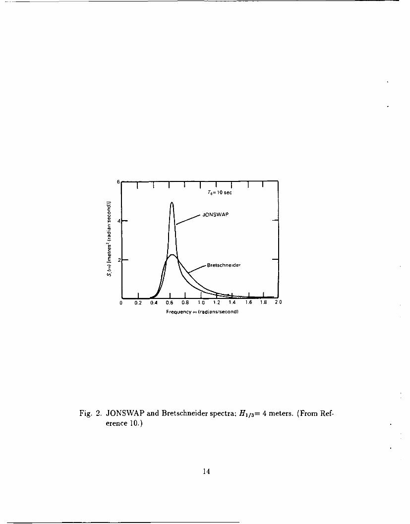
A JONSWAP spectrum can be thought of as a distortion of a Bretschneider spec-
trum in terms of characteristic wave height and modal period'". As shown in Figure 2,
the JONSWAP has a higher peak with a corresponding reduction in spectral ordinate
on either side of the peak. The JONSWAP is more narrow banded than the corre-
sponding Bretschneider. Of course, in comparison to the JONSWAP, the Bretschneider
has a smaller peak, but spreads its energy over a broader band of wave frequencies.
Since pitch and heave motions are heavily damped, with resonant peaks which are not
very pronounced, it is the opinion of the authors that in head seas conditions. little dif-
5

ference will be seen between the JONSWAP model test results and the Bretschneider
SMP84 motion predictions for broad banded responses. (This assumption would not
be acceptable for the lightly damped, narrow band responses such as roll.) The present
state of SMP84 indicates that satisfactory comparisons are made if JONSNWAP model
test data falls within 20% of the SMP84 predictions.
Ship motion predictions for the Thyssen-Waas Mudyug were performed using a
modified version of SMP84 which allowed the use of up to 20 offsets per station. More
than 10 offset points were needed in order to accurately represent the bulges of the
reamers/cutters on the Thyssen-Waas forebody. (See Figure 1). When roll dampening
becomes a major concern, one more consideration is in order when using SMP84 with
Thyssen-Waas hullforms. The centerline ice cutter on the forebody can be visualized
as a "backwards skeg." Although SMP84 allows the use of multiple skegs, it will not
allow the user to describe a skeg which tapers toward the stern6 . This problem was
overcome by modeling an equivalent skeg having the same area and same centers of
pressure as the "backwards skeg." The final SMP84 description of the Thyssen-Waas
Mudyug appears to be reasonable and satisfactory. A comparison between HSVA model
test and SMP84 hydrostatics for the Mudyug are presented in Table 2.
Results
Vertical Displacement and Pitch comparisons between the HSVA model test and
SMP84 predictions are displayed in Tables 3 and 4. Numerical predictions by SMP84
yielded values for ZD that fell easily within 20% of the model test data with the ex-
ception of one case (at the lowest seaway) where the SMP84 prediction was 38% above
HSVA. There is no immediate explanation for the 38% discrepancy in this particular
sea condition. It may be related to the filtering of the acceleration data, ZD. It is
particularly interesting to note in Table 1 that in the lowest sea condition, in head seas,
a high maximum positive peak ZD value was found (3.45 m/s) with a corresponding
calculated value ZD of 1.01 meters. Yet in the second seaway condition, in head seas,
a lower maximum positive peak ZD (3.23 m/s 2 ) was associated with a higher ZD of
2.48 meters. It is impossible to reach definitive conclusions regarding this discrepancy
without the time history data. It is the suspicion of the authors that the model test
6

value for ZD should have been higher than 1.01 meters in this instance. This belief
favors the predicted value of 1.48 meters.
The pitch predictions produced by SMP84 fell easily within 23% of the HSVA model
test values. (See Table 4.) This is very acceptable.
Discussion
Fairly good agreement has been observed between the model test and numerical
predictions of Mudyug head seas vertical acceleration and pitch. This indicates that
numerical prediction techniques might provide appropriate first order predictions for
other Thyssen-Waas hulls forms in head seas conditions. This numerical prediction
technique for vertical motions will now be applied to naval vessels married to Thyssen-
Waas bows.
THYSSEN-WAAS MUDYUG SEAKEEPING STUDY
Seakeeping predictions performed throughout the rest of this study will include
SMP84 calculations in head seas conditions for pitch, heave, and slamming. Slamming
predictions were performed by SMP84 utilizing methods cited by Ochi and Motter.
Motion predictions were performed in longcrested seaways representing Sea States 4
(HI/ 3=6.2 feet-1.88 meters), 5 (H 1/3=10.7 feet-3.25 meters), and 6 (Hl/ 3=16.4 feet-5.0
meters). To maintain consistency in documentation, a seakeeping study was performed
on the Thyssen-Waas Mudyug hull form.
Results
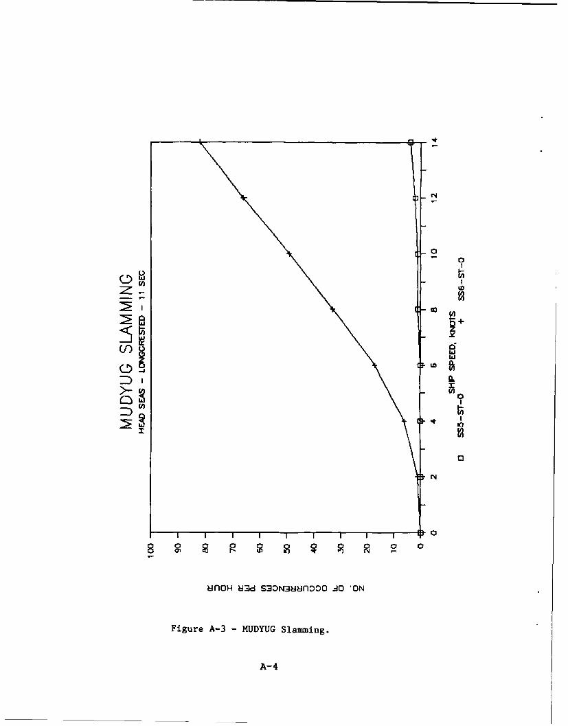
Pitch, heave, and slamming motion predictions are presented in APPENDIX A. Of
particular interest is slamming response. The shallow stem angle and the wide, flat
bottom of the Thyssen-Waas forebody indicate that large forces due to slamming can
occur forward of Station 3. This is significant, since typical slamming studies involved
with conventional hull forms choose the the underside of the hull at station 3 as the
location where the body is flat enough to cause large slamming forces. Since flatness in
the Thyssen-Waas forebodies seemed to occur farther forward in the forebody, a more
representative location was chosen for the slamming calculations. The results predict a
7

significant number of slams at Station 0 at speeds greater than 6 knots in Sea State 6.
These predictions for Mud-yug indicate that slamming might become a problem in the
marriage studies involving the naval combatants.
THYSSEN-WAAS LSD-41 SEAKEEPING STUDY
The first naval hull form for the marriage study was LSD-41. (See Figure 3). This
vessel was of interest due to its amphibious warfare capabilities. The evaluation process
involved with modeling a Thyssen-Waas bow on this class of ship yielded two possible
configurations. In the first case, a hull form which closely resembled the Thyssen-Waas
Mudyug bow was fitted to the bow of the ship in the numerical model. The forebody
contained the same shallow stem angle observed on the Thyssen-Waas Mudyug and was
fitted forward of station 5.5. (See Figure 4). For the purposes of this report, this hull
configuration will be referred to as LSDWAAS.
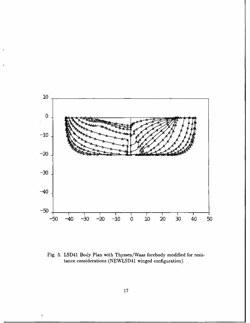
Preliminary estimates, using numerical modeling techniques indicated that LSD-
WAAS had undesirable resistance characteristics. For this reason, a second bow was
fitted to LSD-41 in the numerical model. (See Figure 5). This configuration will be de-
scribed in this report as NEWLSD41. The new forebody represents an altered version
of the Thyssen-Waas forebody to reduce CpF for powering considerations.
Ship motion predictions for the original and two modified LSD hull forms were
made using the modified version of SMP84 which permits the use of up to 20 offsets
per station. The centerline ice cutters on the modified forebodies were modeled as
equivalent skeg having the same area and centers of pressure as the "backwards skeg" in
accordance with SMP84 modeling techniques. Pitch, heave, and slamming predictions
were performed for each hull form configuration.
Results
The general characteristics of the original LSD-41 hull form and the modified ver-
sions are listed in Table 5. Longcrested head seas ship motion predictions for pitch,
heave, and slamming are presented in APPENDIX B.
Both modified Thyssen-Waas (TNWS) forebodies for LSD-41 are predicted to have
higher values for KI, which might cause the vessel to become more stiff in terms of
8

roll. The flat, bulky TNWS forebodies displayed slightly lower SMP84 pitch and heave
motion predictions in the higher sea states in comparison with the original LSD-41
hullform. As illustrated in the slamming figures, both TNWS forebodies are predicted
to experience performance degradations in comparison with the original LSD-41 due to
increased slamming in higher sea states. The projected increase in slamming can directly
be attributed to a shallow draft at the bow combined with the relatively flat, wide
bottom and shallow stem angle of the TNWS forebodies. Limiting speed predictions for
LSD-41 and NEWLSD41 in longcrested, head seas are listed in Table 6. The listed speed
limits are based on SMP84 slamming predictions with a threshold defining unacceptable
slamming at the rate of 20 slams per hour.
THYSSEN-WAAS FFG7 SEAKEEPING STUDY
The second naval hull form for the marriage study was FFG-7. This vessel was
of interest because it represents a typical conventional small naval combatant. The
modified forebody configuration called FFG7WAAS was provided by HSVA. A review
of the underwater hull form in Figures 6 and 7 indicates little change in the underwater
body between the conventional and ice breaking configurations. The most obvious
difference between the two hull forms is that the FFG7WAAS has a shallower stem
and is slightly flatter in the forebody near the FP. The outboard ice cutting keels on
FFG7WAAS are above the waterline. A comparison between FFG-7 and FFG7WAAS
hydrostatics is presented in Table 7.
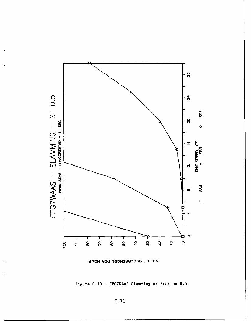
Results
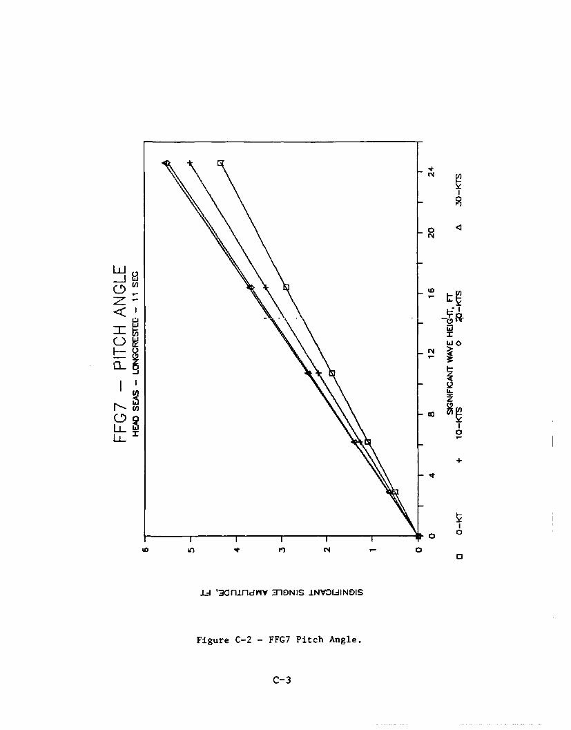
Heave, pitch and slamming comparisons for longcrested seas between FFG-7 and
FFG7WAAS are displayed in APPENDIX C. Pitch and heave responses are predicted
to be very similar for both hull forms due to similarities in the underwater hull configu-
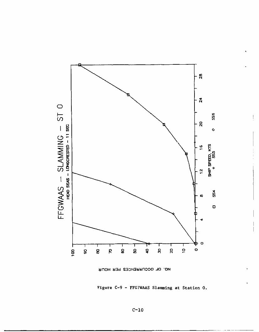
rations. Slamming frequency is predicted to be worse in the FFG7WAAS configuration
due to the shallower stem angle and an increase in flatness of the underwater body
new the FP. Limiting speed predictions for FFG-7 and FFG7WAAS in longcrested,
head seas are listed in Table 8. The listed speed limits are based on SMP84 slamming
predictions with a threshold defining unacceptable slamming at the rate of 20 slams per
9

hour.
CONCLUSIONS
First order numerical predictions of seakeeping performance of a Thyssen-Waas
hullform can be successfully made using a modified version of SMPS4 in head seas,
longcrested seaways. The modified version of SMP84, which allows 20 offsets per sta-
tion to describe the complex Thyssen-Waas forebody, provides credible predictions for
pitch, heave, and slamming. The SMPS4 output appears consistent and follows ex-
pected trends, including the prediction of slamming on the Thyssen-Waas forebody
which is relatively flat, broad in the forebody, and shallow in stem angle as compared
to conventional hull forms. The HSVA model test accomplished its original purpose of
comparing head seas performance of Mudyug before and after the installation of the
Thyssen-Waas forebody, but was lacking in detail and consistency in results to allow
more than a limited comparison with SMP84 predictions.
A close review of the HSVA Mudyug seakeeping model test report8 indicates that a
great deal of attention must be paid to HSVA's conclusion. The HSVA report compared
the original Mudyug hull form with the modified version having the TNWS forebody.
HSVA concluded that "the vertical motions and pitch motions of the ship with the
TNWS forebody were smaller due to the larger and fuller waterline area"'. This state-
ment appears to be valid. However, one should not draw from this statement a conclu-
sion that Thyssen-VWlaas vessels are great seakeepers. It is the authors suspicion that
the original Mudyug was probably a poor seakeeper. Seakeeping improvements made to
the Mudyug by the installation of the TNWS forebody represent minor improvements
to a poor seakeeper.
The T'.,yssen-Waas forebody shows promise in terms of advances in ice breaking
technology. Milano' indicates that this type of vessel is also very promising in terms
of seakeeping performance. Preliminary estimates indicate that hull forms having this
type of forebody will slam more frequently in forward stations than conventional open
water naval vessels. The increase in slamming frequency can directly be attributed to
the flat forebody and shallow stem angle of the TNWS bow.
10

The most promising Thyssen-Waas hull form. the FFG7WAAS represents an TNVS
type configuration which was especially adapted for an FFG-7 by HSVA. The authors of
this report were very encouraged by the implication that TNWS-type forebodies can be
installed on naval combatants with little change in the underwater body. This procedure
of "tailoring" the forebody to the individual vessel appears to allow the creation of ice
breaking hull forms having little change in pitch and heave response, in comparison
with the original body.
RECOMMENDATIONS
It is recommended that further research efforts concerning this topic be directed to-
ward a "tailored" TNWS forebody married to naval combatant. Additional seakeeping
investigations are recommended to explore additional ship motion responses, including
roll. Furthermore, a structural investigation is recommended to predict and quantify
slamming pressures to determine whether or not an increase in slamming frequency is
a serious issue for the ice breaker bow. On the one hand, the ice breaking bow may
have the capability withstand more slamming forces without damage. On the other
hand, the slamming forces may be significant and cause a reduction in open water per-
formance because the ship will need to reduce speed in slamming situations. A partial
degradation in open water slamming performance may be a reasonable trade-off in order
to provide a new ice breaking capability. A model test is strongly advised to confirm
these predictions.
11

10
0 _ _ _ _ _ _ _ _ _
-10
-20
-30
-40
-50-50 -40 -30 -20 -10 0 10 20 30 40 50
Fig. 1. Icebreaker Mudyug Body Plan with Thyssen/Waas forebody.
13
To 10 sec
C0U JONSWAP
C)4-
E2
Bretschneider
0 0.2 0.4 0.6 0.8 1.0 1.2 1.4 1.6 1.8 2.0
Frequency mi (radians/second)
Fig. 2. JONSWAP and Bretschneider spectra; H, 13= 4 meters. (From R-ef-erence 10.)
14

10
0
-10
-20
-30
-40
-50
-50 -40 -30 -20 -10 0 10 20 30 40 50
Fig. 3. LSD41 Body Plan.
15

10
0 _ _ _ _ _ _ _ _ _ _ _ _
-10
-20
-30
-40
-50
-50 -40 -30 -20 -10 0 10 20 30 40 50
Fig. 4. LSD41 Body Plan with Thyssen/Waas forebody (LSDWAAS configuration).
16
10
0
-10
-20
-30
-40
-50 I I I I I1 I I I
-50 -40 -30 -20 -10 0 10 20 30 40 50
Fig. 5. LSD41 Body Plan with Thyssen/Waas forebody modified for resis-tance considerations (NEWLSD41 winged configuration).
17

10
5
0
-5
-10
-15
-20
-25
-30
-30 -20 -10 0 10 20 30
Fig. 6. FFG7 Body Plan.
18

10
5
0
-5
-10
-15
-20
-25
-30
-30 -20 -10 0 10 20 30
Fig. 7. FFG7 Body Plan with Thyssen/Waas forebody modified for resis-tance considerations (FFG7WAAS).
19

-l " C J C ~ m l
17 , c
C:C, r %D - (1-, %
- 2 Ln csj qT P" '-
* l !.0 r n m Ln %D co
r. ~. r . . .u, (N. R'0.
ca r, a~ , m f - e
0' .C9 . 9'l
eq cl f" m- r" cn,
W Fj, 0 000 t
cc (N. m - C! a:ar * c o.:' C
(N Nj U, UN UN UN UN U
'; _ _ _ _ %n_ znu) u)
cr c=! 7- rc C
- co q. f7'o '
00
0~'20

Table 2. Comparison between HSVA "Thyssen/Waas Mudyug" model andSMP84 hydrostatics.
ICEBREAKER "MUDYUG" HYDROSTATICS_* TNWS Forebody Model 3268-0101Parametert HSVA SMP84
Lpp(ft) 257.54 257.54B(ft) 68.63 68.63T(ft) 19.68 19.68
Awp (ft2 ) 17092.7 16750.1CB 0.681 0.676C Af 0.898 0.899
CP0.758 0.752TOS (sec) 10.0 10.0A (LT) 6775.8 6722.5
tNote: 1 foot= 0.3048 meters.
21
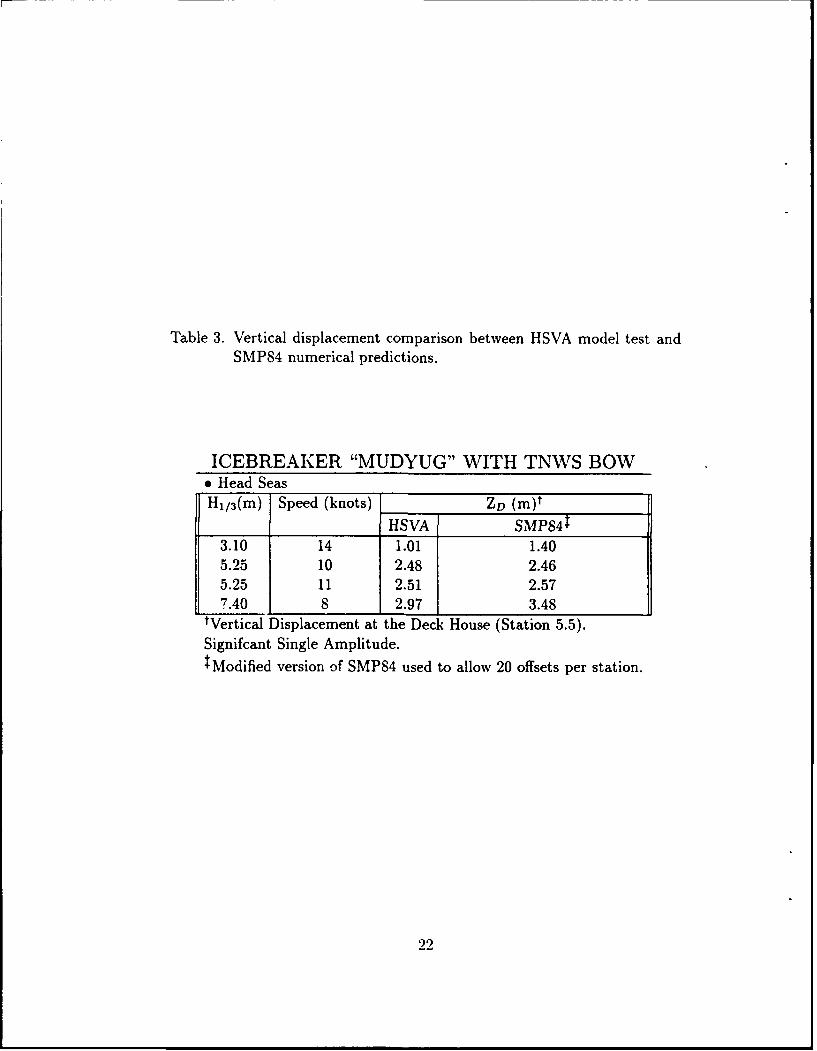
Table 3. Vertical displacement comparison between HSVA model test andSMP84 numerical predictions.
ICEBREAKER "MUDYUG" WITH TNWS BOWe Head SeasH1/ 3 (m) Speed (knots) ZD (M)t
HSVA SMP8413.10 14 1.01 1.405.25 10 2.48 2.465.25 11 2.51 2.577.40 8 2.97 3.48
IVertical Displacement at the Deck House (Station 5.5).Signifcant Single Amplitude.tModified version of SMP84 used to allow 20 offsets per station.
22
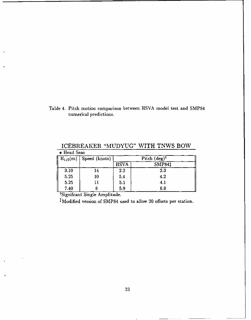
Table 4. Pitch motion comparison between HSVA model test and SMP84numerical predictions.
ICEBREAKER "MUDYUG" WITH TNWS BOWe Head SeasH/a 3 (m) Speed (knots) Pitch (deg)t
HSVA SMP84t3.10 14 2.2 2.35.25 10 5.4 4.25.25 11 5.1 4.17.40 8 5.9 6.0
tSignifcant Single Amplitude.Modified version of SMP84 used to allow 20 offsets per station.
23

Table 5. Comparison between original LDS41 and two proposed ice break-ing versions having TNWS type forebodies.
LSD-41 HYDROSTATICSe SMP84 CalculationsParametert ORIGINAL LSDWAAS NEWLSD41
LwL(ft) 580.0 580.0 580.0B(ft) 84.0 83.6 83.6T(ft) 19.5 17.3 19.5
Awp (ft2 ) 37827.9 45534.3 42170.4
CB 0.583 0.684 0.596CM 0.949 0.987 0.946
p 0.614 0.693 0.630KM 43.2 54.4 46.0
A(LT) 15839.0 16345.3 16111.7tNote: 1 foot= 0.3048 meters.
24

Table 6. LSD limiting speeds (20 SLAMS/HR).
* Longcrested Head SeasSea H/3 T0 LSD-41 NLSDWAAS
State (ft) (sec) Station-3 Station-04 6.2 7 > 30 Kts > 30 Kts5 10.7 9 > 30 Kts 14 Kts6 16.4 11 > 30 Kts 6 Kts7 24.6 13 12 Kts 2 Kts
Note: 1 foot = .3048 meters.
25

Table 7. Comparison between Original FFG-7 and Proposed IcebreakingVersion having a Thyssen-Waas Forebody.
FFG-7 HYDROSTATICS* SMP84 CalculationsParametert ORIGINAL FFG7WAAS
LwL(ft) 408.0 408.0B(ft) 44.8 44.4T(ft) 14.4 14.4
Awp (ft2 ) 13385.5 14166.5CB 0.448 0.450CM 0.749 0.742
p 0.599 0.607KM 22.75 24.37
A(LT) 3373.2 3359.2tNote: 1 foot= 0.3048 meters.
26

Table 8. FFG Limiting Speeds (20 SLAMS/HR).
. Longcrested Head SeasSea HI/ 3 T,, FFG-7 FFG7WAAS
State I(ft) (sec) Station-3 Station-04 6.2 7 > 30Kts 12 Kts5 10.7 9 > 30 Kts 2 Kts6 16.4 11 15 Kts <O0Kt7 24.6 13 9 Kts <OKt
Note: 1 foot = .3048 meters.
27

REFERENCES
1. Milano, V. R., "Hull Forms for U. S. Navy Surface Ship Ice Transit." In: U. S.
Navy Symposium on Arctic/Cold Weather Operations of Surface Ships. Deputy
Chief of Naval Operations for Surface Warfare (Nov 19S9).
2. Riska, K. and P. Varsta, "State of Art Review of Basic Problems for a Naval
Architect," Technical Research Center of Finland, Ship Laboratory 2 (Nov 1977).
3. Dick, R. A. and J. E. Laframboise, "An Empirical Review of the Design Performance
of Icebreakers," Marine Technology, Vol. 26, No. 2 (April 1989).
4. Thomas III, W. L. and L. A. Schultz, "Model Tests of a Naval Combatant in Broken
Ice Fields," Paper presented at the U. S. Second International Conference on Ice
Technology at Cambridge University, Cambridge, U. K. Published in Ice Technology
for Polar Operations by the Wessex Institute of Technology Southampton, U. K.
(Sept 1990).
5. Thomas III, William L., Richard C. Bishop, and Edward A. Devine, "Preliminary
Results of DD-963 Model Tests in Broken Ice Fields," DTRC Report DTRC/SHD-
1315-01 (Jan 1990).
6. Meyers, W. G., T. R. Applebee, and A. E. Baitis, "User's Manual for the Standard
Ship Motion Program, SMP," DTRC Report DTNSRDC/SPD-0936-01 (Sep 1981).
7. Meyers, W. G. and A. E. Baitis, "Improvements to Capability and Predic-
tion Accuracy of the Standard Ship Motion Program, SMP," DTRC Report
DTNSRDC/SPD-0936-04 (Sep 1985).
8. Blume, P., "Seakeeping Tests with the Ice-Breaker Mudyug before and after Con-
version," Hamburg Ship Model Basin Ltd, HSVA Technical Report S 222/6 (May
1986).
9. "Repo-t on Strain and Acceleration Measurements During Seakeeping Tests of
Converted Icebreaker Mudyug," Germanifcher Lloyd Report STB-1501-1906 (Feb
1986).
29

10. Lloyd, R. J. M., SEAKEEPING: Ship Behavior in Rough Weather, Ellis Horwood
Limited (1989).
11. Ochi, M. K. and L. E. Motter, "Prediction of Slamming Characteristics and Hull
Responses for Ship Design," Trans. SNAME, Vol. 81 (1973).
30

APPENDIX A
MUDYUG
A-1

N
14
a.(I)'
D.L a:
D4><.
> I I I I I I -< )N -0 o ~'. ' ' '
IF -
.L '3 nifnfd~iV 3-10NIS INVOLJINE)IS
Figure A-1 MUDYUG Heave Displacement.
A-2

C'LI
N
0
N x
S2
qt 0
0.0 r, N D I)~ PI N 0
030 '3flnfldY4V 710NIS INVOIJINDIS
Figure A-2 - MUDYUG Pitch Angle.
A-3
- +
U)d
CD
0
13. q
:flDH Md S~oN~~flnoo q ~O*N
Figure A-3 - MUDYUG Slamming.
A-4

APPENDIX B
LSD41
B-i

N
2: N
a-I
ILL
0 M
-J
0
LU '3oflind~iV 3-10NIS INVOI.JINDIS
Figure B-i - LSD41 Heave Displacement.
B-2

it
0
N
wL-J
<I
LI
-j
Doa 'GflnfldVIV 3-1DNIS INVOLJINDIS
Figure B-2 - LSD41 Pitch Angle.
B- 3

N
N
cci
It
-1-

N
F-
:2 N
LL
z
0
-B-

w N
0 0
0'0
B-6~

03
N
_ N
f)N
N
I
Figue B- -LD41WAS Sammig. a
B-7

UN
z
C-)
--
U
y.I~N LU
LLa.
0
a.! *1[aU) t q P
-B-

L--
I0
LAJ
C, N>
LUd
Zz
I I I I 0 0
10 r0
.u 'aonlinldV F1NIS 1NVOL-INDIS
Figure B-8 - NEWLSD41 Pitch Angle.
B-9

N
N
CD0N
Cf)
4
-B-

APPENDIX C
FFG7
C-1

4N
z N
Iz
0 N
<I
wI 4z
N P- toI I In N
.Lj '3afllfdhV 310NIS .LNVOLAINDIS
Figure C-i - FFG7 Heave Displacement.
C- 2
N4
N
LJw
CDD
z -
InI
IJ '3n~ndIV TINIS NVOLIINDI
Fiur C- - N7PthAge
I C-3

N
N
(f) 18 N
00
C!) W,
I.t
U--

H-c' 0I~l N
IT)
CD0 Qw F
Crr4
LL 0
8flDH :d S30N:3uun~oo .i0 'ON
Figure C-4 -FFG7 Slamming at Station 0.5.
C-5

uo o
rqJ
mN
00
0.0
Isd
I I I I I I ICfflO Pdd N3 OOq O
CD-
12 0.
cnI
LL
mflOH ud s~oN38unooD .jo *DN
Figure C-5 -FFG7 Slamming at Station 1.
C- 6

coN
N
H-Cf) N
7LLi0
6L<w
I. +
00
unflH U:d s~acm~munooo .D 'ON
Figure C-6 - FFG7 Slamming at Station 3.
C-7

N
WL N
(I)
to
n~ N
-a I
CI)
+
LL-
N i- C0 O W 10 K 4t M' N '- 0
iAL'3 rCfJfdIV 319NIS .LNVOLANDIS
Figure C-7 - FFG7WAAS Heave Displacement.
C-8

N
N
L-J
i0J
ow I
I I.
U--
GoN
N< HC)
0
"'--
I ILL
cn q 8 R
uIOH 13d s3oN0ufnI I1 7 O 0'ON
Figure C-9 - FFG7WAAS Slamming at Station 0.
C-10
LC) '4oN
(InC-D
CD 13
LL '4
80 ca F0 0-O
IflD Nd s~oN38unooo joi 'ON
Figure C-10 - FFG7WAAS Slamming at Station 0.5.
c-11

N
N_ 0
--
8 8f8 8 9
unOHM~d MN3 ~jnoo -A 'O
Fiur C-1-FGWA lmmnNtSain1
CfC-12

,
N
N
H-(f)
wN
000
LI]IA
r--q
CDLL
I I I I I I I I I -o0
mflOH U3d SMN3mufnO0 -40 'ON
Figure C-12 - FFG7WAAS Slamming at Station 3.
C-13