Embed Size (px)
Citation preview

Fuel Cell Seminar & Exposition 2011
October 31st – November 3rd, 2011
Orlando, Florida, USAwww.ogura-clutch.com
Janusz Blaszczyk, Ph.D.Hydrogen Recirculation Technology Development
Ogura Industrial Corporation

There are several key factors for proper anode gas mixture
recirculation in Fuel Cell systems and they can be
classified as follows:
• Ensure Minimum Anode dP across the stack (keep
the channels clear from the liquid water droplets)
• Provide sufficient humidification of the gas mixture in
the anode inlet
• Satisfy stack requirement with respect to the “H2
Stoichiometry”
Typically, some sort of Hydrogen Recirculation Device
(HRD) is used and it has to be able to move the amount of
gas that satisfies all of the requirements listed above, or in
other words to provide adequate anode gas recirculation..
1.0 Importance of Hydrogen Recirculation in PEM Fuel Cell Systems

1.1 Minimum Anode dP• Crucial for FC Stack durability: Clearing
the channels of water droplets
• Typically the minimum Anode dP is
around 30 mbard.
• This parameter can be measured
directly
Water droplets in plate channels
1.2 Anode Inlet Humidification (RH%)• Adequate humidification is crucial to stack performance
• This parameter can be measured directly

1.3 H2 Stoichiometry DefinitionH2 Stoichiometry is a requirement provided by FC stack
manufacturer.
H2Stoich = Vh_1/Vh_feed (1)
Where
H2Stoch – Hydrogen Stoichiometry
Vh_1 – stream of dry hydrogen in the stack inlet
Vh_feed – stream of hydrogen consumed by the stack
Anode gas composition: H2, Water Vapour, Nitrogen
Volume of ballast gases: 70%
Challenge: determine which part of the recirculated gas
mixture is hydrogen.
(important for warranty disputes, trouble shooting, etc.)

1.4 Measurements of HRB Performance
Parameters
• It is relatively easy to measure directly two of the three
listed HRB performance parameters – these are:
Anode dP
Anode Inlet Humidification (RH%)
• A direct measurement of the third parameter,
H2Stoich or Anode Outlet Gas
Mixture flowrate (from which H2Stoich
could be calculated)
using traditional gas flowrate measurement methods is
not practical because the recirculated gas is a mixture
of gases, and because of liquid water droplets
presence in the gas stream, which considerably affects
readings of the instruments.

0
500
1000
1500
2000
2500
1 2 3 4 5 6 7 8 9 10 11 12 13 14 15
An
od
e I
nle
t G
as
Mix
Flo
w R
ate
, s
lpm
Anode Gas Mixture Compositiondepends on recirc blower volumetric efficiency
H2Orec @6Krpm H2Orec @5Krpm
HO2rec @4Krpm N2rec @6Krpm
N2rec @5Krpm N2rec @4Krpm
H2rec @6Krpm H2rec @5Krpm
H2rec @4Krpm H2feed_slpm
H2feed_slpm H2feed_slpm6000 rpm 5000 rpm
4000 rpm
H2%out:
95% 85% 80% 75% 65%H2%out:
95% 85% 80% 75% 65%H2%out:
95% 85% 80% 75% 65%
Vol Efficiency increases with N2% increase and RPM increase
Fig. 1 Example of Anode Gas Mixture Compositions

2.0 Hydrogen Stoich Determination
Fig. 2 Fuel Cell Anode Loop
Fuel Cell
Stack
Purge Valve
Hydrogen Recirculation Blower (Ogura TX technology)
Feed H2
Recirculated Anode Gas Stream
1 2 3
45

2.0 Hydrogen Stoichiometry Determination
It is possible to measure the H2 concentration in a dry gas
mixture of H2 and N2* in the stack inlet and outlet ( H2%in
and H2%out) with standard chromatograph.
The following equations can be written for the system
presented in Figure 2:
H2%in = (Vh_feed + Vh_2)/(Vh_feed + Vh2 + Vn) (2)
H2%out = Vh_2/(Vh_2 + Vn) (3)where
H2%in, H2%out – Hydrogen concentrations in the stack inlet and
outlet, respectively (measured parameters)
Vh_feed – stream of Hydrogen consumed by the stack
Vh_2 – stream of recirculated Hydrogen
Vn – stream of Nitrogen (assumed the same in the stack inlet and
outlet)*) N2 is almost always present in the anode gas mixture due to the diffusion
through MEA. With proper setting of purge valve V1 the N2 concentration can
be controlled and maintained at desired level.
2.0 Hydrogen Stoichiometry Determination
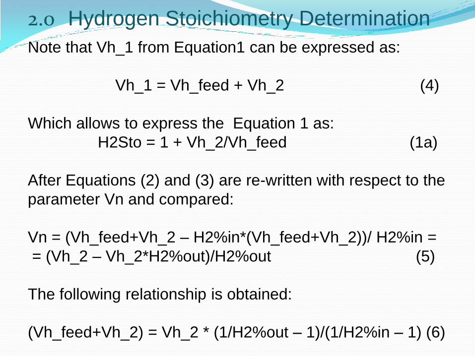
Note that Vh_1 from Equation1 can be expressed as:
Vh_1 = Vh_feed + Vh_2 (4)
Which allows to express the Equation 1 as:
H2Sto = 1 + Vh_2/Vh_feed (1a)
After Equations (2) and (3) are re-written with respect to the
parameter Vn and compared:
Vn = (Vh_feed+Vh_2 – H2%in*(Vh_feed+Vh_2))/ H2%in =
= (Vh_2 – Vh_2*H2%out)/H2%out (5)
The following relationship is obtained:
(Vh_feed+Vh_2) = Vh_2 * (1/H2%out – 1)/(1/H2%in – 1) (6)

2.0 Hydrogen Stoichiometry Determination
After terms containing directly measured parameters (H2%in
and H2%out) are separated from the other terms, the
Equation 6 takes the following form:
Vh_feed/Vh_2 = (1/H%out – 1)/(1/H2%in – 1) – 1 (6a)
Left part of which contains elements of Equation 1a.
After Equation (6a) is combined with Equation (1a) the
following expression for H2Sto is obtained:
H2Sto = H2%out * (1- H2%in) / (H2%in – H2%out) + 1 (7)
Where
H2Sto - Hydrogen stoichiometry
H2%out, H2%in – molar concentrations of H2 on dry basis in stack
outlet and inlet, respectively, expressed as a fraction of 1 (not as %).

3.0 Method Accuracy Discussion
The method accuracy depends on the following factors:
H2% measurement accuracy
Chosen H2 concentration level in the stack inlet
which is controlled by the anode gas purge rate
Actual recirculation rate (stoichiometry)
Actual purge rate
The effect of the first three factors is presented in the next
2 slides.
Typically, the hydrogen losses due to purging are at the
0.5% consumption level, therefore the effects of purge
losses on the concentrations are negligible in most of the
cases. If required, a correction factor in Equation 3 can be
introduced to compensate the Vh_2 and Vn difference in
the stack inlet and outlet.

3.0 Method Accuracy DiscussionFig. 3 Method Errors at 95% H2 dry @ Stack Inlet

2.0 Method Accuracy DiscussionFig. 4 Method Errors at 85% H2 dry @ Stack Inlet
Practical method range

3.0 Method Accuracy Discussion
The presented method is relatively simple to use, however,
the user should pay attention to the actual conditions at
which the H2 Stoich is determined.
General method application “rules of thumb” are:
• Higher recirculation rates cause larger errors, however,
at high recirculation rates the stack is usually “happy”
and larger errors in determining the recirculation rate
are tolerable.
• Higher H2 concentration levels result in higher errors –
recommended H2%dry at stack inlet is 80 - 85%
(controlled by purge rate)
• A small stream of N2 can be introduced into the anode
recirculated mixture in order to increase the method
accuracy. This stream has to be be compensated by
purge to maintain mass balance in anode loop.
.

4.0 Examples of HRD Characteristics:
4.0 Example of HRD Characteristics:
After the H2 Stoich is determined from Equation 7, it is
possible to determine the HRD volumetric efficiency and
actual performance (recirculated anode gas volumetric
flow rate):
The Vh_feed can be calculated from the Current
Sensor reading (it also includes a purge flow rate)
The recirculated dry H2 stream (Vh_2) is calculated
from Equation 1a.
The nitrogen content in recirculated gas is calculated
from Equation 5.
The water vapour content is calculated from the RH%
direct measurement.
The resulting HRB characteristics are presented in the
next few slides.

4.0 Examples of HRD Characteristics:
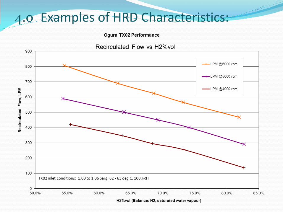
4.0 Examples of HRD Characteristics:
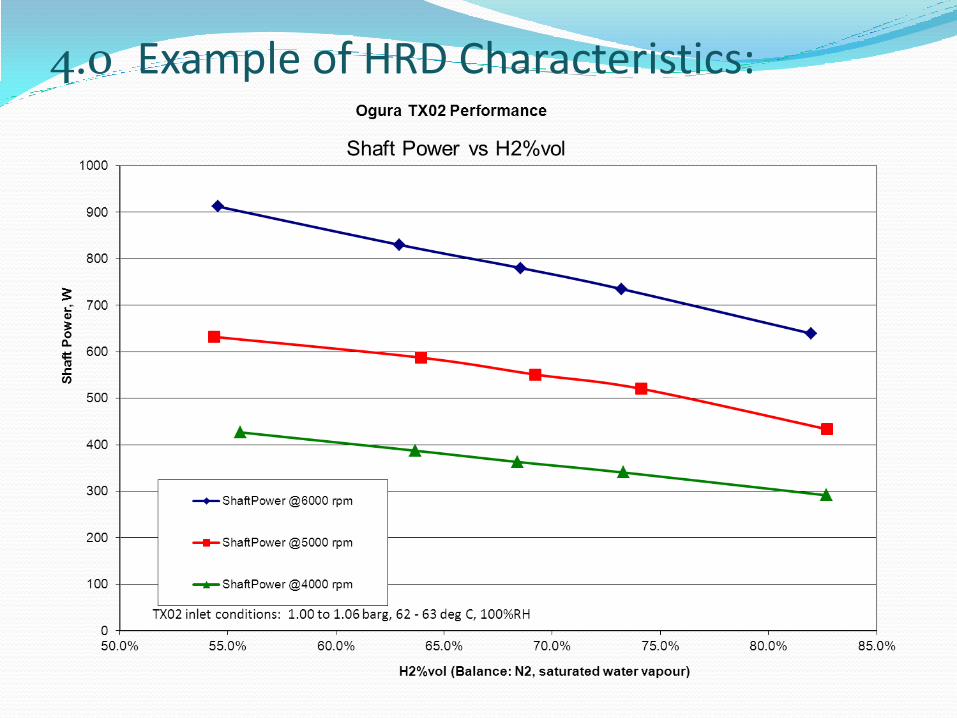
4.0 Example of HRD Characteristics:

4.0 Example of HRD Characteristics:

5.0 AcknowledgmentsThe presented work has been accomplished during Ogura-
Ballard joint program towards Hydrogen Recirculation Blower
development, as a result of which Ogura long-life, high
efficiency TX04U-M roots type blower has been developed and used in Ballard FCvelocity®-HD6 bus module.

For further information please contact:
Hydrogen Stoich Measurement MethodologyJanusz Blaszczyk (presently): Director of Engineering, Shanghai Everpower Technologies Ltd., [email protected] or [email protected]
TX TechnologyFred Cacace: Ogura USA, Industrial Product Manager, [email protected]://www.ogura-clutch.com/pdfs/http___www.altenergymag.com_emagazine.pdf
Questions?
Thank You For your Time…www.ogura-clutch.com