Embed Size (px)
DESCRIPTION
Canadian manual for the Javelin anti-tank guided missile launcher.
Citation preview
JAVELIN S-15 DRILL BOOK(ENGLISH)
(Becomes effective upon receipt)
Issued on authority of the Chief of the Land Staff
B-GL-372-006/FP-001
WARNING
ALTHOUGH NOT CLASSIFIED, THIS PUBLICATION, OR ANY PART OF IT,MAY BE EXEMPTED FROM DISCLOSURE TO THE PUBLIC UNDER THEACCESS TO INFORMATION ACT. ALL ELEMENTS OF INFORMATIONCONTAINED HEREIN MUST BE CLOSELY SCRUTINIZED TO ASCERTAINWHETHER OR NOT THE PUBLICATION, OR ANY PART OF IT, MAY BERELEASED.
Canada

Javelin S-15 Drill Book
i
FOREWORD
1. B-GL-372-006/FP-001, Javelin S-15 Drill Book, is issued onthe authority of the Chief of the Land Staff.
2. This publication is effective on receipt.
3. Suggestions for amendments should be forward throughnormal channels to the Director Army Doctrine, Attention DAD 7,Fort Frontenac, PO Box 17000 Station Forces, Kingston, ON,K7K 7B4.
4. Unless otherwise noted, masculine pronouns apply to bothmen and women.
5. The NDID for the French version of this publication isB-GL-372-006/FP-002. The terminology used in this publication isconsistent with the Army vocabulary.
© 2000 DND/MDN Canada
Javelin S-15 Drill Book
iii
TABLE OF CONTENTS
FOREWORD ................................................................................. i
CHAPTER 1 THE JAVELIN MISSILE SYSTEM
General .................................................................................... 1
Role ......................................................................................... 1
The Javelin Detachment .......................................................... 2
Javelin Detachment Stores....................................................... 2
Responsibilities........................................................................ 2
Duties....................................................................................... 2
Description .............................................................................. 4
Characteristics ......................................................................... 6
Guidance.................................................................................. 9
Coverage.................................................................................. 9
Climatic Operating Ranges...................................................... 9
Drop Limits ........................................................................... 10
Air Portability........................................................................ 10
Safety Precautions ................................................................. 10
Safety Aspects of the Weapon Site........................................ 11
CHAPTER 2 DEPLOYMENT AND ENGAGEMENT DRILLS
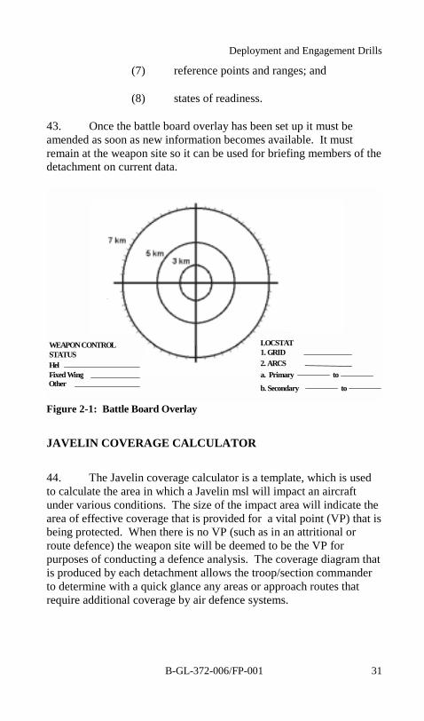
RV Drills ............................................................................... 15
Duties at the RV—Section Commander ................................ 15
Detachment Commander at the RV....................................... 15
Weapon Site Data Card ......................................................... 16
Into Action Drills................................................................... 16
Load....................................................................................... 17
Unload ................................................................................... 19
Reload.................................................................................... 20
Lightweight Multiple Launcher Drills ................................... 20

B-GL-372-006/FP-001
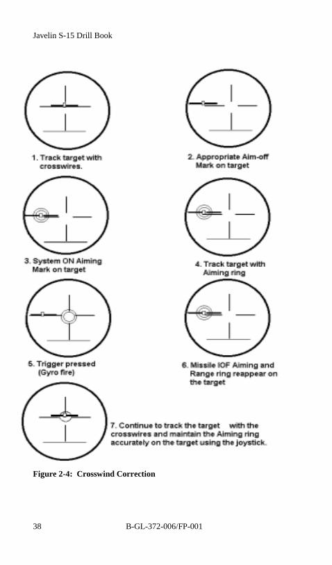
iv
Load....................................................................................... 22
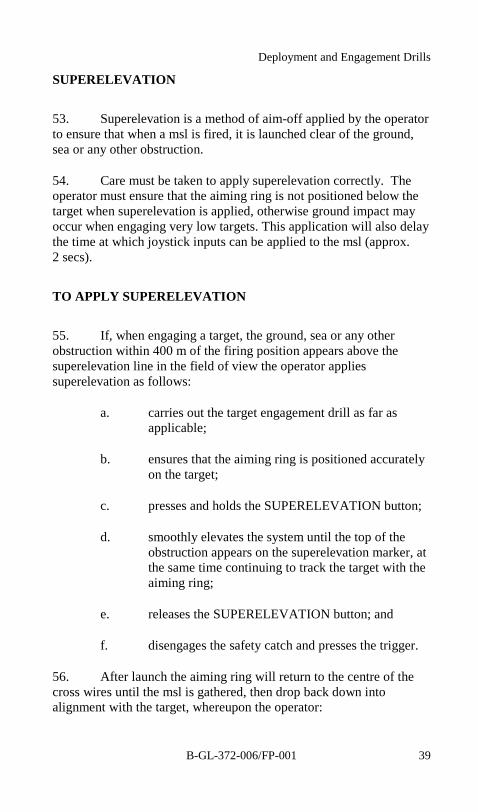
To Unload.............................................................................. 24
Reload.................................................................................... 25
Misfire Drills ......................................................................... 25
First Stage Misfire Drills ....................................................... 26
Second Stage Misfire Drills................................................... 29
Detachment Commander's Battle Board Overlay.................. 29
Javelin Coverage Calculator.................................................. 31
Drills for Use ......................................................................... 33
Worm Rule (Calculation of Angle of Sight).......................... 35
Lead Angle ............................................................................ 35
To Apply Lead Angle............................................................ 36
Crosswind Correction............................................................ 37
To Apply Crosswind Correction............................................ 37
Superelevation ....................................................................... 40
To Apply Superelevation....................................................... 39
To Apply Crosswind Correction and Superelevation ........... 41
Action on Drills ..................................................................... 42
Receipt of Early Warning...................................................... 42
Sighting a Target ................................................................... 43
Engagement of a Target......................................................... 43
Termination of an Engagement ............................................. 43
Terminating an Engagement.................................................. 44
Re-engaging the Same Target................................................ 44
Engaging a Fresh Target........................................................ 45
Prepare to Move .................................................................... 45
Cease Firing........................................................................... 47
Emergency Engagement ........................................................ 48
Target Engagement (One Person Operation)......................... 49
Javelin S-15 Drill Book
v
Position of Assembly............................................................. 50
Executive Orders and Miscellaneous Reports ....................... 50
Target Selection..................................................................... 53
Distribution of Fire ................................................................ 54
CHAPTER 3 DISABLEMENT OF EQUIPMENT
General .................................................................................. 55
Temporary Disablement ........................................................ 55
Destruction ............................................................................ 55
Priority for Destroying Javelin .............................................. 55
Disposal of Unserviceable Missiles....................................... 56
Demolition of Missiles .......................................................... 57
CHAPTER 4 CARE AND MAINTENANCE
Servicing................................................................................ 61
Cleaning Procedures .............................................................. 62
Verifications .......................................................................... 63
Role of the First Line Test Set ............................................... 65
Purpose and Function ............................................................ 66
FLTS CONTROLS AND FUNCTIONS............................... 67
Physical Data ......................................................................... 70
Aiming Unit Testing.............................................................. 70
First Line Test Set Testing..................................................... 70
Preparation for Tests.............................................................. 70
FLTS Switch ON Procedure.................................................. 71
Built In Test Procedures ........................................................ 71
FIRST LINE TEST SET Built In Test................................... 73
Built In Test Conclusion........................................................ 76
Preparation for Tests (Sl)....................................................... 76
Aiming Unit Test Procedure.................................................. 78
Shoulder Launch Tests Conclusion ....................................... 93

B-GL-372-006/FP-001
vi
Lightweight Multiple Launcher Tests ................................... 93
Lightweight Multiple Launcher Tests Conclusion ............... 97
Aiming Unit Stabilization Test.............................................. 97
Aiming Unit Stabilization Test Conclusion........................... 99
Anti-icing Procedure ............................................................. 99
Application of Anti-icing Fluid ........................................... 100

Javelin S-15 Drill Book
vii
TABLE OF FIGURES
Figure 1-1: The Efflux Zone ............................................................ 11Figure 2-1: Battle Board Overlay...................................................... 31Figure 2-2: Coverage Calculator ...................................................... 34Figure 2-3: Lead Angle .................................................................... 36Figure 2-4: Crosswind Correction.................................................... 38Figure 2-5: Superelevation Correction............................................. 40Figure 2-6: Crosswind and Superelevation ...................................... 42Figure 3-1: Layout of Plastic Explosives ......................................... 59
Javelin S-15 Drill Book
B-GL-372-006/FP-001 1
CHAPTER 1THE JAVELIN MISSILE SYSTEM
GENERAL
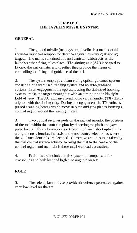
1. The guided missile (msl) system, Javelin, is a man-portableshoulder launched weapon for defence against low-flying attackingtargets. The msl is contained in a msl canister, which acts as thelauncher when firing takes place. The aiming unit (AU) is shaped tofit onto the msl canister and together they provide the means ofcontrolling the firing and guidance of the msl.
2. The system employs a beam-riding optical guidance systemconsisting of a stabilised tracking system and an auto-guidancesystem. In an engagement the operator, using the stabilised trackingsystem, tracks the target throughout with an aiming ring in his sightfield of view. The AU guidance head houses a transmitter (TX) that isaligned with the aiming ring. During an engagement the TX emits twopulsed scanning beams which move in pitch and yaw planes forming acontrol region around the "in-flight" msl.
3. Two optical receiver pods on the msl tail monitor the positionof the msl within the control region by detecting the pitch and yawpulse bursts. This information is retransmitted via a short optical linkalong the msls longitudinal axis to the msl control electronics wherethe guidance demands are decoded. Corrective action is then taken bythe msl control surface actuator to bring the msl to the centre of thecontrol region and maintain it there until warhead detonation.
4. Facilities are included in the system to compensate forcrosswinds and both low and high crossing rate targets.
ROLE
5. The role of Javelin is to provide air defence protection againstvery low-level air threats.
Javelin S-15 Drill Book
B-GL-372-006/FP-0012
THE JAVELIN DETACHMENT
6. The detachment consists of four personnel:
a. the detachment commander;
b. the operator;
c. the driver/ communicator; and
d. the 2 I/C.
7. All personnel should be qualified Javelin Gunner. Theestablished detachment is four personnel, but restrictions may reducethis to two personnel. In either case, two personnel will be deployedwith the weapon when it is tactically sited on the battlefield.
JAVELIN DETACHMENT STORES
8. Depending on the type of operation, Javelin detachmentstores will include one AU and up to six msls. This represents threedays supply; the fourth day (to complete the basic load of 8 msls) isheld by the Javelin Support Troop.
RESPONSIBILITIES
9. The detachment commander, No. 1, is responsible to thesection commander for the efficient operation of his detachment. Thedetachment commander ensures the safety and protection of allpersonnel on the weapon site. He is also responsible for themaintenance of all equipment issued to his detachment. The operator,No. 2, performs his duties under the supervision of No. 1. The driver,No. 3, is responsible for the vehicle, and the communicationsequipment. He performs his duties under the supervision of No. 1.The 2 I/C, No. 4, performs his duties under the supervision of No. 1.
DUTIES
10. No. 1 is in command of the detachment and will:
The Javelin Missile System
B-GL-372-006/FP-001 3
a. ensure that all rules and SOPs are observed duringthe engagement of a target;
b. maintain his battle board, ensuring that the operatorhas all the necessary information;
c. ensure that all necessary reports are passed to thesection commander or higher, as applicable;
d. ensure that communications are maintained with thecontrol station of his net;
e. establish communications between the firingposition and stand easy;
f. orders the proper fuze setting and crosswind;
g. relieve and assist the operator as necessary;
h. ensure that the detachment stores are accounted for,as per the checklist, and in working order at alltimes;
i. ensure that all equipment is correctly loaded andsafely secured prior to moving the detachmentvehicle;
j. supervise the maintenance and testing of thedetachment equipment and report all malfunctionsimmediately; and
k. ensure that a system of relief is instituted to enableeither himself or the 2I/C to be one of the twopersonnel at the weapon position.
11. No. 2 works under the direction of No. 1 and will:
a. ensure that he is familiar with the Weapons ControlStatus, rules of engagement, SOPs and allrestrictions relating to the weapon site beingoccupied;

Javelin S-15 Drill Book
B-GL-372-006/FP-0014
b. engage targets;
c. record battery usage; and
d. assist No. 1 as necessary.
12. No. 3 works under the direction of No. 1 and will:
a. ensure that he is familiar with the Weapon ControlStatus, rules of engagement, SOPs and allrestrictions relating to the weapon site beingoccupied;
b. ensure his vehicle and communications equipment isin working order at all times; and
c. assist No. 1, No. 2 or No. 4 as necessary.
13. No. 4 is second in command of the detachment, and will:
a. perform the same duties as the No. 1; and
b. assist No. 1, No. 2 or No. 3 as necessary.
DESCRIPTION
14. The Javelin system consists of the following equipment:
a. Main Assemblies:
(1) guided msl, HE K106 A1 orK140 A1; and
(2) AU (AU).
b. Ancillary Equipment:
(1) First Line Test Set (FLTS) to provide aportable means for Pass/Fail testing of theAU, LML and the FLTS itself. Thecomplete FLTS is contained in a
The Javelin Missile System
B-GL-372-006/FP-001 5
lightweight field handling container thatalso contains one spare lithium battery, twospare fuses, two spare collimator lamps,test adapter, Beta Light and a specialscrewdriver are also carried in thiscontainer. A shipping and storagecontainer carries the FLTS within its fieldhandling container.
(2) Lightweight Multiple Launcher (LML)increases the engagement rate for theGuided Msl System Javelin and removesthe effects of weight loss. The LMLconsists of two sections: the traverse headand the tripod. The LML provides a meansof physically supporting and holding threecanistered msls and an AU and provides theelectrical connections necessary to initiatethe firing and subsequent control of the mslfrom the AU.
c. Training Equipment:
(1) Part task trainer (Javelin).
(2) Drill canister provides an inert canister fordrill and handling purposes. It has the samedimensions, weight and balance as anoperational canister.
(3) Training canister to provide a facility forAU training in a non-firing environment,and is transported in a field-handlingcontainer. It consists of an empty mslcanister containing interface circuitry,which allows all the AU electronics to bepowered up, with the exception of the TXunit in the guidance head.

Javelin S-15 Drill Book
B-GL-372-006/FP-0016
CHARACTERISTICS
15. Msl characteristics are:
a. Propulsion—two stage, solid propellant motor(Crake smokeless platinized cordite).
b. Warhead—blast fragmentation with animpact/graze & proximity fuse.
c. Maximum speed—Mach 1.4.
d. Power supply—27.5 to 35.5 volts (nominal 30 V)DC, provided by thermal battery in msl.
e. Dimensions:
(1) Msl:
(a) length = 1345 mm;
(b) body diameter = 76 mm;
(c) wing span = 275 mm; and
(d) weight = 12.7 kg.
(2) Msl in Canister:
(a) length = 1390 mm;
(b) forward tube diameter = 197 mm;
(c) rear tube diameter = 95 mm; and
(d) weight = 15.2 kg
(3) Msl canister in field handling container(FHC):
(a) length = 1454 mm;

The Javelin Missile System
B-GL-372-006/FP-001 7
(b) forward tube diameter = 233 mm;
(c) rear tube diameter = 135 mm; and
(d) weight = 18.7 kg.
(4) FHC in full standard pack (FSP):
(a) length = 1580 mm;
(b) height = 353 mm;
(c) width = 330 mm; and
(d) weight = 43.5 kg.
16. AU Characteristics:
a. Power Supply. A 31 volts DC is provided by adisposable, long-life lithium battery mountedexternally on the rear of the control unit.
b. TX. A laser generated, pulsed beam pattern.
c. Optics:
(1) monocular, field of view (FOV)—180 mils;and
(2) magnification—6 times.
d. TX Beam Dispersion:
(1) wide—142 mils; and
(2) narrow—4.7 mils.
e. Dimensions:
(1) AU—408 mm x 342 mm x 203 mm;
Javelin S-15 Drill Book
B-GL-372-006/FP-0018
(2) FHC—482.6 mm x 431.8 mm x 271.8 mm;and
(3) FSP)—573 mm x 482.6 mm x 339 mm.
f. Weight:
(1) AU—8.5 kg;
(2) AU in FHC—9.7 kg; and
(3) FHC in FSP—20.5 kg.
17. LML Characteristics:
a. Operational weights:
(1) traverse head—15.6 kg;
(2) FHC—18.2 kg;
(3) tripod stand—14.7 kg; and
(4) FHC—16.0 kg.
b. Deployment limits:
(1) levelling adjustments to compensate forslopes up to plus 10 degrees or minus 10degrees—176 mils;
(2) height adjustments to compensate foroperator size:
(a) minimum height—1.6 m; and
(b) maximum height—1.9 m.

The Javelin Missile System
B-GL-372-006/FP-001 9
GUIDANCE
18. Guidance is semi-automatic command to line of sight(SACLOS), by means of a line of sight beam rider (LOSBR) with aninitial gathering phase.
COVERAGE
19. Javelin provides the following coverage:
a. Bearing—6400 mils.
b. Elevation (maximum firing):
(1) shoulder launcher (SL)—176 mils to+800 mils; and
(2) LML—176 mils to +500 mils.
c. Maximum Standard Intercept Range:
(1) 4.5 km—highly manoeuvring targets; and
(2) 5.5 km—stationary or direct approachingtargets.
d. Minimum Intercept Range—350 m.
CLIMATIC OPERATING RANGES
20. The system can be operated under the following conditions:
a. Temperature—from –30ºto +60ºC.
b. Pressure—altitudes up to 1500 m above sea level.
c. Wind—in crosswinds up to 25 knots (46 km/h).
d. Humidity—up to +40ºC at 95%.
Javelin S-15 Drill Book
B-GL-372-006/FP-00110
e. Javelin Part Task Trainer—from –20ºC to +52ºC.
DROP LIMITS
21. The maximum drop height the canister/ msl can withstandwithout sustaining internal damage is as follows:
a. unpacked canister—25 cm; and
b. canister in FHC or FSP—75 cm.
AIR PORTABILITY
22. The equipment can be lifted by helicopter and transported byunpressurized aircraft up to 10,000 feet above sea level.
SAFETY PRECAUTIONS
23. The Pressure Equilization Valve (PEV) must be operated for7 sec before the canister is removed from the FHC.
24. The operator must never look at the sun through themonocular sight. The detachment commander must take this intoaccount when carrying out an engagement and must be prepared tocease the engagement if necessary.
25. When operating, the system presents a laser hazard (NominalOptical Hazard Distance - NOHD) out to 2 m in front of the AU forthe naked eye and out to16 m (Enhanced NOHD - ENOHD) if lookingthrough 8 X binoculars.
26. The Javelin laser is classified 3B.
NOTE
If the aiming unit is dropped it must be tested usingthe FLTS.
Javelin S-15 Drill Book
B-GL-372-006/FP-001 11
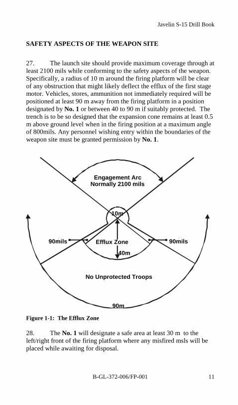
SAFETY ASPECTS OF THE WEAPON SITE
27. The launch site should provide maximum coverage through atleast 2100 mils while conforming to the safety aspects of the weapon.Specifically, a radius of 10 m around the firing platform will be clearof any obstruction that might likely deflect the efflux of the first stagemotor. Vehicles, stores, ammunition not immediately required will bepositioned at least 90 m away from the firing platform in a positiondesignated by No. 1 or between 40 to 90 m if suitably protected. Thetrench is to be so designed that the expansion cone remains at least 0.5m above ground level when in the firing position at a maximum angleof 800mils. Any personnel wishing entry within the boundaries of theweapon site must be granted permission by No. 1.
Figure 1-1: The Efflux Zone
28. The No. 1 will designate a safe area at least 30 m to theleft/right front of the firing platform where any misfired msls will beplaced while awaiting for disposal.
90m
10m
Engagement ArcNormally 2100 mils
90mils 90mils
No Unprotected Troops
Efflux Zone
40m
Javelin S-15 Drill Book
B-GL-372-006/FP-00112
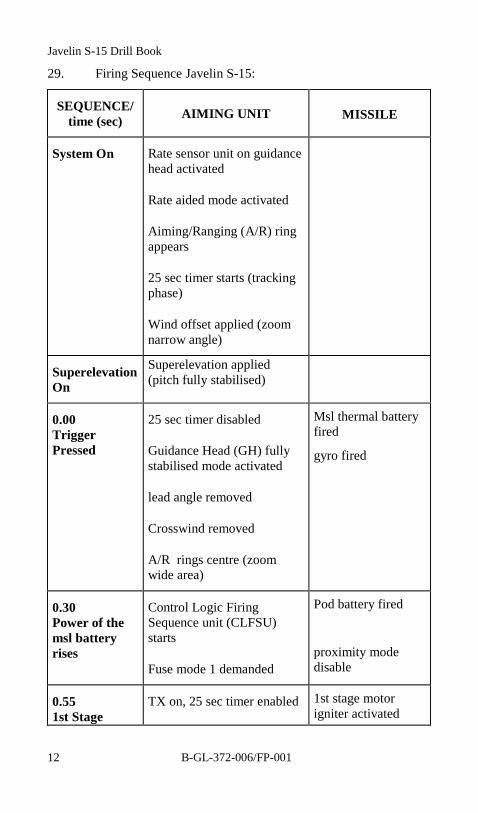
29. Firing Sequence Javelin S-15:
SEQUENCE/time (sec) AIMING UNIT MISSILE
System On Rate sensor unit on guidancehead activated
Rate aided mode activated
Aiming/Ranging (A/R) ringappears
25 sec timer starts (trackingphase)
Wind offset applied (zoomnarrow angle)
SuperelevationOn
Superelevation applied(pitch fully stabilised)
0.00TriggerPressed
25 sec timer disabled
Guidance Head (GH) fullystabilised mode activated
lead angle removed
Crosswind removed
A/R rings centre (zoomwide area)
Msl thermal batteryfired
gyro fired
0.30Power of themsl batteryrises
Control Logic FiringSequence unit (CLFSU)starts
Fuse mode 1 demanded
Pod battery fired
proximity modedisable
0.551st Stage
TX on, 25 sec timer enabled 1st stage motorigniter activated

The Javelin Missile System
B-GL-372-006/FP-001 13
SEQUENCE/time (sec) AIMING UNIT MISSILE
Motor Ignition (engagement phase)
Wind offset reapplied
Gravity compensation starts
0.58 Msl Launched
Bore Riding Pin(BRP) released,PhotodiodeDeploymentMechanismreleased,Ignition,Safety andArming Unit (ISAU)starts
0.852nd StageIgnition
Joy Stick (J/S) enabled,feed-forward starts (if nosuperelevation applied)
1.35 Start superelevation decay
1.732nd StageEnds
1.95 Ranging ring off Fully armed
2.15 Superelevation decay ends
J/S enabled
Feed-forward ends
4.55 J/S ramp starts
13.5 Zoom ends
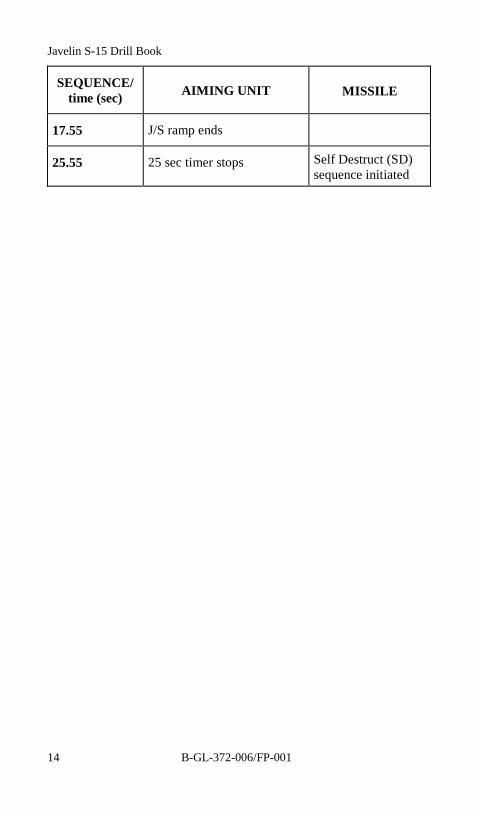
Javelin S-15 Drill Book
B-GL-372-006/FP-00114
SEQUENCE/time (sec) AIMING UNIT MISSILE
17.55 J/S ramp ends
25.55 25 sec timer stops Self Destruct (SD)sequence initiated
Javelin S-15 Drill Book
B-GL-372-006/FP-001 15
CHAPTER 2DEPLOYMENT AND ENGAGEMENT DRILLS
RV DRILLS
1. RV drills are as follows:
a. approach RV from the opposite direction of threat;
b. maintain dispersion as packet slows down;
c. get off road as soon as possible and maintain trackplan;
d. all vehicles are backed into their appropriate spots;
e. detachment vehicles should be spread out 50 mapart;
f. camouflage all vehicles, set-up local defences andreceive orders.
DUTIES AT THE RV—SECTION COMMANDER
2. Section commander will lead the section into the RV andassign them a parking area. He will then deploy air, ground, and NBCsentries and ensure vehicles are camouflaged. He will co-ordinate thelocal defence and ensures that the detachments know their crash drillsand where to go. After the detachments have departed he will reportthe state of the section to the Troop commander (ammo, casualty, etc.)as well as get briefed on any liaison to be performed.
DETACHMENT COMMANDER AT THE RV
3. The detachment commander is responsible to ensure that thetrack plan is maintained, and that dispersion, camouflage and noisepolicies are adhered to. He must also ensure that the detachmentknows the password, where the command post is, and the direction ofthe threat. He will then report for orders.
Javelin S-15 Drill Book
B-GL-372-006/FP-00116
WEAPON SITE DATA CARD
4. The Weapon Site Data Card contains all the informationrequired to enable the detachment commander to carry out theoccupation of his Javelin site. The section commander will completeas many serials of the site data card as possible in the time availablefor reconnaissance. A sketch of the Javelin site will be drawn on thereverse side of the Weapon Site Data Card if required to assist thedetachment commander in carrying out his deployment. It should onlybe used when:
a. the position is difficult to occupy;
b. the position is to be occupied at night; and
c. time permits.
INTO ACTION DRILLS
5. The detachment vehicle should be driven as close to theposition as possible, but not so close as to jeopardise the tactical valueof the position (100 m is the rule of the thumb).
ACTION
6. Upon arrival at the desired location, No. 1 will order “HALT,ACTION”.
a. No. 1 will carry one msl in its FHC and thenecessary stores to a suitable interim position.
b. No. 2 will carry one msl in its FHC, the AU in itsFHC, and a lithium battery to the interim position.
c. No. 3 will assist in the off loading of equipment,remove the vehicle from the weapon site,camouflage the vehicle in the location indicated byNo. 1 and will bring the remaining equipmentrequired by the detachment.
Deployment and Engagement Drills
B-GL-372-006/FP-001 17
d. Upon arrival at the interim position No. 1 orders“LOAD” and assisted by No. 2 carries out the loaddrill.
e. No. 1 designates interim arcs to No. 2.
f. No. 1 reports “READY” to higher.
g. No. 1 physically recces 100 m around his positionfor the, misfire pit, rest area, and alternate position,and for the best Javelin position available unless hehas been ordered otherwise by the section or troopcommander.
h. No. 1 adopts the best position (or the position asordered) and briefs the No. 2, No. 3 and No. 4 on thearcs and tactical situation.
i. No. 1 establishes the work routine.
j. No. 1 prepares the battle board.
LOAD
7. No. 1 orders “LOAD”.
8. No. 2 unpacks the AU from its FHC, removes the opticsprotective cover and checks that:
a. the trigger is in the safe position;
b. the SYSTEM switch is set to OFF;
NOTE
When mating or unmating the aiming unit personnelmust avoid using the control handle assembly toprevent damage.

Javelin S-15 Drill Book
B-GL-372-006/FP-00118
c. the monocular and TX optics are clean andundamaged;
d. the interface connector is clean and serviceable;
e. the humidity indicator is blue;
f. ensures the fuze switch is positioned to 2, unlessotherwise ordered; and
g. the battery is correctly fitted in the AU.
9. No. 1 opens a msl FHC and operates the PEV on the mslcanister for seven seconds.
10. No. 1 checks that:
a. the front cover is undamaged and correctly fitted tothe msl canister;
b. the msl canister forward tube is not fractured ordelaminated;
c. the hand locator is securely attached (see note );
d. the forward tube is securely attached to thediaphragm, in that the manacle clamp is secured andis located within 3 cm of the thermal batteryhousing;
e. the diaphragm is not fractured;
f. the humidity indicator is blue;
g. the interface connector is clean and undamaged;
h. the rear tube is not dented or cracked and there areno flaws in the metal;
i. the expansion cone is not damaged in such a waythat it will obstruct the blow-out panel; and
j. the blow out panel is undamaged and secure.
Deployment and Engagement Drills
B-GL-372-006/FP-001 19
11. No. 1 supports the msl canister in a vertical position, the frontcover resting on a firm flat surface.
12. No. 2 fits the AU to the diaphragm ensuring that the AUretaining catch is locked.
13. No. 1:
a. opens the FHC of the second msl and carries out thechecks;
b. replaces the socket protective cap; and
c. replaces the second msl in its FHC and places it in asafe position near the operator.
14. No. 2 takes post.
UNLOAD
15. No. 1 orders “UNLOAD”and prepares the next msl.
16. No. 2 ensures the SYSTEM switch is OFF.
NOTE
1. If any fault is found during the checks (exceptitem c), that round must not be fired until it hasbeen examined and cleared by an AmmunitionTechnician.
2. If the hand locator is not secure, exceptionalcare must be taken during firing that theoperator adopts the correct position with his lefthand.
Javelin S-15 Drill Book
B-GL-372-006/FP-00120
17. No. 2 assisted by No. 1, supports the msl canister in a verticalposition, front cover resting on a firm, flat surface.
18. No. 2 removes the AU from the diaphragm.
RELOAD
19. No. 1 orders, "RELOAD".
20. Reload sequence:
a. No. 2 ensures that:
(1) the trigger is at SAFE;
(2) the SYSTEM switch is set to OFF;
b. No. 1 operates the msl canister PEV for sevenseconds if required, removes the socket protectivecap and supports the msl canister in a verticalposition, front cover resting on a firm, flat surface.
c. No. 2 fits the AU to the diaphragm ensuring that theAU retaining catch is locked.
LIGHTWEIGHT MULTIPLE LAUNCHER DRILLS
21. The deployment of the LML is an upgrade to an existingfiring position and will be used if the expected or actual time on taskexceeds 2 hours. The LML will be deployed on order, after thedetachment commander has confirmed the permanent firing position.
22. After camouflaging the detachment vehicle, No.3 carries thetripod, traverse head and a msl to the position and observes the arcswhile No. 1 and No. 2 perform their drills.
23. No. 1 and No. 2 carry out the following drill:
a. No. 1 and No. 2 remove the tripod from its FHC andsupport it on its base plate.

Deployment and Engagement Drills
B-GL-372-006/FP-001 21
b. No. 1:
(1) centres the three adjustment studs (approx.1 cm of thread showing at the head); and
(2) holds the support tripod in a verticalposition.
c. No. 2:
(1) unfolds all three legs and engages the leglatches;
(2) unclamps the support collar by turning itanti-clockwise until it reaches the stop;
(3) firmly slides the support collar to thebottom of the support tube and releases theleg retaining latches;
(4) clamps the support collar by turning itclockwise;
(5) levels the tripod using the hand adjustmentstuds; and
(6) pickets the foot pads and base plate to theground.
24. No. 1:
a. removes the traverse head from its FHC and ensuresthat the support tube pintle and the traverse headinner sleeve are free from obstructions and dirt;
b. mounts the traverse head on to the support tubepintle;
c. unclamps the sight arm from its stowed position andswings the arm downward into the horizontalposition; pushes the sight arm fully forward until
Javelin S-15 Drill Book
B-GL-372-006/FP-00122
the pin in the sight arm support tube engages thenotch of the sight arm casting; and
d. ensures that the sight arm clamping screw is lockedtightly prior to mating the AU with the sight armassembly.
25. No. 1 prepares the required three msls and orders “LOAD”.
LOAD
26. No. 1 orders “LOAD” and removes the three msl interfaceconnector covers on the traverse head, and checks to ensure that theconnectors are clean and serviceable.
27. No. 2 holds the traverse head stationary, ensuring elevationlock is engaged.
28. No. 1 and No. 2 load three msl canisters as follows (seenotes):
a. No. 1 holding the msl canister with the left handhalfway along its length and the right hand under theforward tube, places the rear tube into the loadingchute, ensuring that the alignment of the diaphragmand the chute is correct.
b. No. 2 steadies the LML with his left hand andsupports the rear tube, while No. 1 pushes the mslcanister fully home until the spring retaining clipengages with a "click".
c. No. 1 checks the humidity indicator for correctlocation. If any red shows the msl canister isremoved and replaced by another.
d. No.3 holds the sight arm stationary.
e. No. 2 removes the protective cap from the interfaceconnector and checks to ensure that the connector isclean and serviceable.

Deployment and Engagement Drills
B-GL-372-006/FP-001 23
f. No. 1 and No. 2 unmate the AU from the diaphragmof the loaded msl.
g. No. 2:
(1) fits the AU to the sight arm diaphragm;
(2) ensures the AU retaining catch is locked;and
(3) selects the first msl.
h. No. 1 places the original msl canister in a FHC.
i. No. 1 checks the level of the LML and if necessary,orders No. 2 to re-level using the hand adjustmentstuds.
j. No. 2:
(1) adjusts the height of the AU eyepiece usingthe height adjustment sleeve on the supporttube;
(2) releases the elevation lock; and
(3) observes the primary arc.
Javelin S-15 Drill Book
B-GL-372-006/FP-00124
TO UNLOAD
29. No. 1 orders “UNLOAD”.
30. No. 1 places the msl FHCs close to the LML.
31. No. 2:
a. ensures that the SYSTEM switch is at OFF;
b. engages the elevation lock; and
c. releases the msl canister retaining catch of each mslin turn in the order bottom inner, top inner and topouter.
32. No. 1 unloads the msl canisters, replaces their interfaceconnector protective caps and secures them in the FHCs.
33. No. 2 replaces the interface protective plugs of the traversehead.
WARNING
When loading the second missile, care must be takenthat the expansion cone does not damage the frontcover of the first missile.
NOTE
1. Msl canisters are to be loaded in the followingsequence: top outer, top inner, bottom inner.
2. A single missile may be loaded into any chute;however, the missile selector switch must be setto the corresponding position.
Deployment and Engagement Drills
B-GL-372-006/FP-001 25
RELOAD
34. No. 1 orders “RELOAD” and prepares the required msls.
35. No. 2:
a. sets the SYSTEM switch to OFF;
b. engages the elevation lock;
c. assists No. 1 with the loading of the msl(s);
d. No. 1 removes the fired canister and places it to oneside;
e. No. 1 loads one msl canister;
f. No. 2 selects msl no. 1;
g. No. 1, if necessary, orders, “RELOAD TWO/THREE”;
h. No. 1 and No. 2 carry out the reload drill on eachmsl canister in turn;
i. No. 2 releases the elevation lock; and
j. No. 1 and No. 2 continue normal observation.
MISFIRE DRILLS
WARNING
In peacetime this drill is modified as per Chapter 9,Section 3 of B-GL-304-003/TS-OA1.
Javelin S-15 Drill Book
B-GL-372-006/FP-00126
FIRST STAGE MISFIRE DRILLS
36. If after pressing the trigger the msl fails to launch, theimmediate action is for the No. 2 to fully release the trigger and safetycatch, disengage the safety catch and press the trigger a second time.If the msl launches, the operator continues the engagement.
37. In SL mode if the msl again fails to launch within threeseconds, No. 2 reports, “MISFIRE” and:
a. No. 2 keeps the weapon on the shoulder, triggerengaged with the system pointed within safe arcs,for ONE MINUTE.
b. After one minute has elapsed, No. 1 orders“MISFIRE, UNLOAD”.
c. No. 2 releases the trigger and ensures that the safetycatch is at Safe and sets the SYSTEM switch toOFF.
d. No. 2 keeping system parallel to the ground lowersthe weapon and gives it to No. 1, who holds it withone hand on each side of the AU. No. 1 and No. 2rotate the AU upside down maintaining a safe pointof aim.
e. No. 2 removes the AU from the diaphragm, andadopts a crouching position until No. 1 is clear ofthe site.
f. No. 1 places the msl canister in a safe area/misfirepit, ensuring that the msl canister remains pointingin a safe direction.
g. No. 1 orders, “LOAD”. No. 1 and No. 2 carry outthe necessary load drill.
38. In the LML mode if the msl fails to launch within threeseconds, No. 2 reports, “MISFIRE NUMBER ONE” (two or three)and:
Deployment and Engagement Drills
B-GL-372-006/FP-001 27
a. No. 2:
(1) fully releases the trigger and safety catch;
(2) sets the SYSTEM switch to OFF;
(3) using the msl selector switch, selects thenext msl for firing;
(4) sets the SYSTEM switch to ON;
(5) re-engages the target;
(6) if a msl launches, continues with theengagement. On completion of theengagement carries out the misfire drill;
(7) if the msl fails to launch, reports“MISFIRE NUMBER 2”(three); and
(8) keeps the system pointed within safe arcsfor one minute timed from the last reportedmisfire.
b. After one minute has elapsed from last misfire,No. 1 orders, “MISFIRE, UNLOAD”.
c. No. 2:
(1) releases the trigger and safety catch;
(2) sets the SYSTEM switch to OFF;
(3) engages the elevation lock;
WARNING
If the second and third missiles misfire, the thirdmust be unloaded first.
Javelin S-15 Drill Book
B-GL-372-006/FP-00128
(4) holds the traverse head while No. 1 movesto the front of the LML, being careful notto allow any part of his body to pass behindor in front of the msl canisters; and
(5) holds the traverse head stationary andoperates the msl canister retaining catch.
d. No. 1:
(1) removes the misfired canister clear of theLML, ensuring that the expansion conedoes not point at the remaining mslcanisters and removes the misfired canisterto a safe area;
(2) if more than one misfire has occurred, thedrill is repeated; and
(3) orders “LOAD”. No. 1 and No. 2 carry outthe necessary load drill (see Notes).
NOTE
1. If more than one missile has misfired, fullaiming unit tests are to be carried out before thereload is ordered.
2. Misfires are disposed of IAW SOPs (see alsoChapter 3).
Deployment and Engagement Drills
B-GL-372-006/FP-001 29
SECOND STAGE MISFIRE DRILLS
39. When a msl is launched but the second stage motor does notignite the drill is as follows for both SL and LML:
a. No. 1 orders “TAKE COVER”; and
b. No. 1 assesses tactical scenario, and decides whetherto continue in his present position or to move to thealternate.
40. The msl is electrically charged, and therefore armed, for 45minutes. The detachment commander must take this, and the locationof the misfired missile, into account when deciding whether or not tomove to the alternate position.
DETACHMENT COMMANDER'S BATTLE BOARDOVERLAY
41. The battle board is designed to enable the detachmentcommander to record pertinent information from the Weapon SiteData Card and any identifiable reference objects. These will be usedto brief his detachment and give search and engagement orders. Thebattle board overlay is printed on matte talc and is scaled to be used inconjunction with any map of 1:50,000 scale. It consists of an outerring representing a radius of 7 km, scribed in 100 mils increments, andtwo inner circles with representative radii of 5 km and 3 km and acentre point which represents the firing position. The lower left andright corners of the overlay are devoted to an aide-memoire, whichincludes the following:
a. LOCSTAT with:
WARNING
In peacetime this drill is modified as per Chapter 9,Section 3 of B-GL-304-003/TS-OA1.
Javelin S-15 Drill Book
B-GL-372-006/FP-00130
(1) grid of Javelin position; and
(2) primary and secondary arcs.
b. Weapon control status (WCS).
42. Upon occupying his position the detachment commander willset up the overlay as follows:
a. orient his map;
b. locate and place the centre of the overlay over theJavelin position;
c. complete the aide-memoire by filling out the locstate, and weapon control status;
d. number the outer ring;
e. mark on primary and secondary arcs (secondary arcsif not given by troop/section commander should beselected by detachment commander and adoptedafter confirmation with section/troop CP);
f. identify and mark any prominent objects or featureswithin the arcs; and
g. mark any other pertinent information, such as:
(1) local defences;
(2) other air defence weapons or units;
(3) position of troop CP;
(4) positions of friendly troops;
(5) transit routes, air corridors, etc., which maybe of assistance in completing the assignedtask;
(6) air defence warning;
Deployment and Engagement Drills
B-GL-372-006/FP-001 31
(7) reference points and ranges; and
(8) states of readiness.
43. Once the battle board overlay has been set up it must beamended as soon as new information becomes available. It mustremain at the weapon site so it can be used for briefing members of thedetachment on current data.
WEAPON CONTROLSTATUSHelFixed WingOther
LOCSTAT1. GRID2. ARCSa. Primary to
b. Secondary to
Figure 2-1: Battle Board Overlay
JAVELIN COVERAGE CALCULATOR
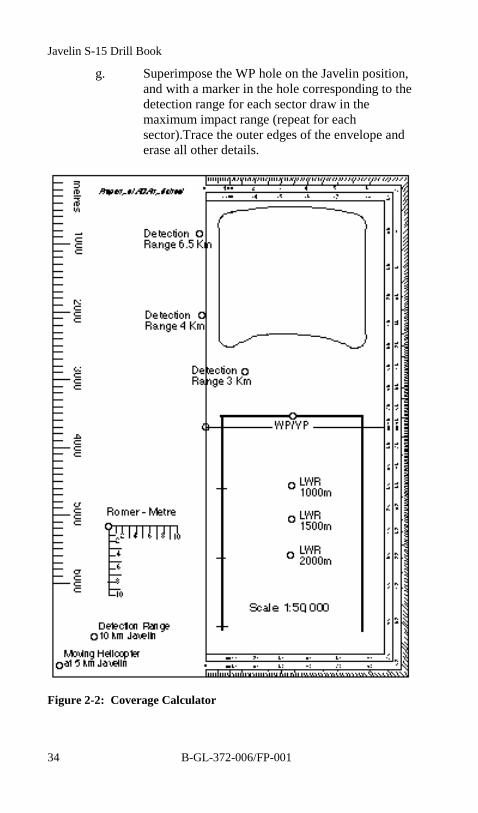
44. The Javelin coverage calculator is a template, which is usedto calculate the area in which a Javelin msl will impact an aircraftunder various conditions. The size of the impact area will indicate thearea of effective coverage that is provided for a vital point (VP) that isbeing protected. When there is no VP (such as in an attritional orroute defence) the weapon site will be deemed to be the VP forpurposes of conducting a defence analysis. The coverage diagram thatis produced by each detachment allows the troop/section commanderto determine with a quick glance any areas or approach routes thatrequire additional coverage by air defence systems.
Javelin S-15 Drill Book
B-GL-372-006/FP-00132
45. Successful engagements are based on four criteria:
a. target speed of 250 m/s;
b. operator reaction time of seven seconds (target at250 m/s covers 1750 m in seven seconds);
c. maximum of 500 m from detachment to VP;
d. line of weapon release/1000 m, 1500 m or 2000 m;and
e. the calculator is based on two of these factors:
(1) target speed of 250 m/s; and
(2) reaction time of seven seconds.
46. Characteristics:
a. The coverage calculator is transparent (for mapwork).
b. Impact/Envelope box is cut out 1 km right and leftof centre axis.
c. The two parallel lines extending down 4 km arereferred to as fly lines. They are used to indicatecrossing targets to the Weapon Position (WP).
d. Twelve holes are cut out for:
(1) Weapons position.
(2) Line of weapon release (LWR)—1000 m,1500 m, 2000 m. Type of target and theweapons likely to be used against itdetermine the LWR. The troop commanderwill order the LWR based on his threatassessment.

Deployment and Engagement Drills
B-GL-372-006/FP-001 33
(3) Five detection ranges—3 km, 4.5 km,6.5 km and 10 km (for fast moving targets),plus a 5 km detection range (for movinghelicopters). The box that the template willproduce shows where target and msl meet.
(4) An impact box is used in conjunction withthe fly lines to verify if engagements on theleft and right arcs will present crossingtargets.
(5) Romer.
DRILLS FOR USE
47. On a piece of talc, produce a coverage trace in the followingmanner:
a. Plot the VP if any.
b. Plot the Javelin position.
c. Insert pencil in hole marked WP and place it overthe VP with a marker (red) in the appropriate LWRrange, draw a circle around the VP.
d. Determine arcs and plot them from the Javelinposition.
e. With the hole marked WP superimposed over theJavelin position, align the bottom left corner of theimpact box with the left arc, if the VP falls outsidethe fly lines, that particular arc should change.Adjust the corner until the VP falls inside the flylines, this should be your new left-of-arc. Repeat forthe right arc.
f. Divide into sectors as determined by the unmaskedcalculations (see para 48 below) and mark eachsector.
Javelin S-15 Drill Book
B-GL-372-006/FP-00134
g. Superimpose the WP hole on the Javelin position,and with a marker in the hole corresponding to thedetection range for each sector draw in themaximum impact range (repeat for eachsector).Trace the outer edges of the envelope anderase all other details.
Figure 2-2: Coverage Calculator
Deployment and Engagement Drills
B-GL-372-006/FP-001 35
WORM RULE (CALCULATION OF ANGLE OF SIGHT)
48. A Javelin position is limited in its line of sight by obstaclesand wood line crests. The effectiveness of the system is reducedbecause the detachment cannot see a fast approaching target until it istoo late. The detachment must be aware of the exact ranges a targetwill appear or unmask itself to the detachment, above the crest orobstacle. As soon as possible after occupying a Javelin position, inorder that the section/troop commander can assess his section/troopcoverage and ensure that all likely approaches of a target are covered,the detachment commander must:
a. determine arcs;
b. identify any obstacles in the arcs;
c. estimate the range from position to the obstacles orcrests using the map;
d. determine the angle of sight of the obstacle using theformula—angle of sight (in mils) = difference inheight (m) of the position and the height of thecrest ÷ range in km; and
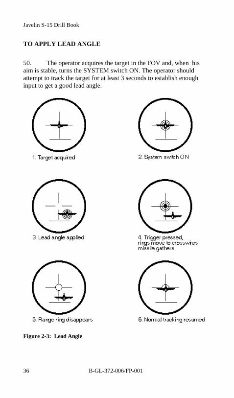
e. using an unmasked increment chart or graph,determine the range increment, add it to the rangefrom the position to crest, and get the unmaskedrange for that obstacle.
LEAD ANGLE
49. As the operator tracks the target, rate gyroscopes in theoptical head detect the movements of the AU. The outputs of thesegyroscopes are fed to the mirror servo system to automatically correctthe position of the rings in the monocular field of view. When the mslis fired it will appear ahead of a crossing target ( i.e. a lead angle isintroduced to the tracking system before launch).
Javelin S-15 Drill Book
B-GL-372-006/FP-00136
TO APPLY LEAD ANGLE
50. The operator acquires the target in the FOV and, when hisaim is stable, turns the SYSTEM switch ON. The operator shouldattempt to track the target for at least 3 seconds to establish enoughinput to get a good lead angle.
Figure 2-3: Lead Angle

Deployment and Engagement Drills
B-GL-372-006/FP-001 37
CROSSWIND CORRECTION
51. Crosswind correction is only necessary for winds in excess of15 knots, blowing across the line of sight. It should be noted that largetrees sway noticeably in a 15 knot wind. To determine wind directiona suitable, inconspicuous marker (such as a strip of hesian or sandbagtied to a branch) should be placed immediately in front of the firingposition.
TO APPLY CROSSWIND CORRECTION
52. Having first determined that the wind speed is in excess of 15knots and at or near to a right angle to the direction of fire, theoperator carries out the following:
a. Sets the CROSSWIND CORRECTION switch toeither:
(1) the left position, if the wind is blowingfrom the left; or
(2) the right position, if the wind is blowingfrom the right.
b. Acquires the target in the FOV by placing it at theextreme left or right (left correction = left side) ofthe horizontal aiming mark.
c. Turn the SYSTEM switch ON.
d. Continues with the engagement.
e. Immediately after launch, smoothly re-lays thecentre of the sight on the target and then continues totrack the target, at the same time keeping the aimingring accurately aligned with the target throughoutthe engagement, by means of the joystick.
Javelin S-15 Drill Book
B-GL-372-006/FP-00138
Figure 2-4: Crosswind Correction
Deployment and Engagement Drills
B-GL-372-006/FP-001 39
SUPERELEVATION
53. Superelevation is a method of aim-off applied by the operatorto ensure that when a msl is fired, it is launched clear of the ground,sea or any other obstruction.
54. Care must be taken to apply superelevation correctly. Theoperator must ensure that the aiming ring is not positioned below thetarget when superelevation is applied, otherwise ground impact mayoccur when engaging very low targets. This application will also delaythe time at which joystick inputs can be applied to the msl (approx.2 secs).
TO APPLY SUPERELEVATION
55. If, when engaging a target, the ground, sea or any otherobstruction within 400 m of the firing position appears above thesuperelevation line in the field of view the operator appliessuperelevation as follows:
a. carries out the target engagement drill as far asapplicable;
b. ensures that the aiming ring is positioned accuratelyon the target;
c. presses and holds the SUPERELEVATION button;
d. smoothly elevates the system until the top of theobstruction appears on the superelevation marker, atthe same time continuing to track the target with theaiming ring;
e. releases the SUPERELEVATION button; and
f. disengages the safety catch and presses the trigger.
56. After launch the aiming ring will return to the centre of thecross wires until the msl is gathered, then drop back down intoalignment with the target, whereupon the operator:

Javelin S-15 Drill Book
B-GL-372-006/FP-00140
a. keeps the aiming ring accurately aligned with thetarget by means of the joystick; and
b. smoothly depresses the system until the cross wiresare aligned with the target.
Figure 2-5: Superelevation Correction
.

Deployment and Engagement Drills
B-GL-372-006/FP-001 41
TO APPLY CROSSWIND CORRECTION ANDSUPERELEVATION
57. To apply both crosswind correction and superelevation, theoperator carries out the two drills inclusive. Immediately after launch,the operator:
a. smoothly re-lays in azimuth until the vertical crosswire is in line with the target; and
b. maintains the same elevation.
58. When the msl has gathered and the aiming ring has droppeddown into alignment with the target, the operator:
a. keeps the aiming ring accurately aligned with thetarget by means of the joystick; and
b. smoothly depresses the system until the cross wiresare aligned with the target.

Javelin S-15 Drill Book
B-GL-372-006/FP-00142
Figure 2-6: Crosswind and Superelevation
ACTION ON DRILLS
RECEIPT OF EARLY WARNING
59. On receiving an early warning:
a. No. 1 orders “TAKE POST”, uses the battle boardto relate situation to the primary arc.
b. No. 2 adopts the ready position with system onshoulder observing arcs.
,
Deployment and Engagement Drills
B-GL-372-006/FP-001 43
c. No. 1 and No. 2 observes in the direction of the OPwarning. If a target is seen, the drill continues.After 2 minutes if no target is seen or heard, No. 1may order “REST”. No. 1 and No. 2 maintains avisual watch over the alerted sector in addition to theprimary arc, for a further three minutes.
SIGHTING A TARGET
60. The first member of the detachment to see a target in the areawill inform the other by reporting “TARGET” and indicating itslocation using the reference points for the Javelin position.
61. No. 2 will locate the target and report “SEEN”, set the fuzeand the CROSSWIND CORRECTION switch as ordered , shoulderthe system or verify msl selector (LML) and identify as “HOSTILE”,“FRIENDLY” or “NOT RECOGNIZED”. Tracking will continueuntil the detachment commander orders "REST". This will notnormally be ordered unless the aircraft is identified as Friendly.
62. No. 1 will ensure that a full report of the sighting is made tothe next higher authority immediately.
ENGAGEMENT OF A TARGET
63. No. 1 must confirm target is “HOSTILE”.
64. No. 1 will assess situation and order “ENGAGE”.
65. No. 2 will acquire and track the target. (If the target is notimmediately acquired he will look over the sight to search the arc andthen again attempt to acquire)
66. No. 2 operates the firing trigger, or upon receipt of the order“HOLD FIRE” carries out the appropriate drills.
TERMINATION OF AN ENGAGEMENT
67. An engagement is terminated when:
Javelin S-15 Drill Book
B-GL-372-006/FP-00144
a. the target is recognised as friendly or friendlyaircraft are endangered;
b. the msl is seen to successfully intercept with thetarget;
c. the msl is seen to self destruct; or
d. ground impact is observed.
TERMINATING AN ENGAGEMENT
68. To terminate an engagement, the No. 1 can order “HOLDFIRE” and the No. 2 carries out the following drill:
a. Prior to msl launch, No. 2
(1) sets the SYSTEM switch to OFF; and
(2) prepares to engage another target.
b. After msl launch:
(1) No. 2 steers the msl to a safe area and thensets the SYSTEM switch to OFF;
(2) No. 1 and No. 2 carry out the reload drill orNo. 2 selects the next msl (LML);
(3) No. 2 prepares to engage another target.
RE-ENGAGING THE SAME TARGET
69. If the AU shuts down or, it is obvious to the No. 1, the mslhas missed but the target is still in range, No. 1 orders, “RE-ENGAGE”.
70. No. 2:
a. sets the SYSTEM switch to OFF;
Deployment and Engagement Drills
B-GL-372-006/FP-001 45
b. reloads or selects the next msl (LML);
c. sets the SYSTEM switch to ON; and
d. re-acquires, tracks and engages the target.
ENGAGING A FRESH TARGET
71. When the msl is seen to hit, or the target is no longer inrange, and a fresh target is available, No. 1 orders, “TARGETLEFT/RIGHT, ENGAGE”.
72. No. 2:
a. sets the SYSTEM switch to OFF;
b. reloads or selects the next msl (LML);
c. locates the new target and reports “SEEN”.
73. No. 1 and No. 2 identify the target as“HOSTILE/FRIEND/NOT RECOGNIZED” as applicable.
74. No. 2 acquires, tracks and engages the new target.
PREPARE TO MOVE
75. On receipt of the order “PREPARE TO MOVE”, No. 1 hasall equipment (less the detachment vehicle which remainscamouflaged), removed from the position except:
a. two msls;
b. AU with spare battery;
c. radio and No. 1 stores; and
d. trench camouflage net.
Javelin S-15 Drill Book
B-GL-372-006/FP-00146
76. Unless otherwise specified, the LML will be disassembled asfollows:
a. No. 1 orders “PREPARE TO MOVE, UNLOAD”.
b. No. 3 maintains observation of the arcs.
c. No. 2:
(1) ensures that the SYSTEM switch is at OFF;
(2) engages the elevation lock;
(3) releases the msl canister retaining catch ofchute 3.
d. No. 1 unloads a msl canister from the LML.
e. No. 1 supports the msl canister in a vertical position,the front cover resting on a firm flat surface.
f. No. 3 holds the sight arm stationary.
g. No. 2 removes the AU from the sight arm.
h. No. 2 fits the AU to the msl ensuring that the AUretaining catch is locked and gives it to the No. 3who returns to observing the arcs.
i. No. 1 and No. 2 continue to carry out the unloaddrill on the LML.
j. No. 1 unclamps the sight arm from its operationalposition and clamps it in the stowed position.
k. No. 1 removes the traverse head from the tripod andsecures it in its FHC.
l. No. 1:
(1) removes the pickets from the foot pads andbase plate; and

Deployment and Engagement Drills
B-GL-372-006/FP-001 47
(2) unclamps the support collar.
m. No. 2 raises the height adjustment sleeve of thesupport tube.
n. No. 1 and No. 2:
(1) raise the support collar to the top of thesupport tube and clamp it;
(2) close the three legs with their pads flatagainst the support tube;
(3) lower the height adjustment sleeve; and
(4) place the tripod into its FHC.
o. No. 1, No. 2 resume observing the arcs while fillingthe trench to stage 2.
p. No. 3 stows all unnecessary equipment in thevehicle.
CEASE FIRING
77. When the order “CEASE FIRING” is received from thesection commander the site will be evacuated. On receipt of the order:
a. No. 1 will:
(1) order “CEASE FIRING, UNLOAD”;
(2) secure his battle board;
(3) assist No. 2 in removing the AU from themsl canister;
(4) replace the protective cap on the interfaceconnector and then secure the msl canisterin its FHC;
Javelin S-15 Drill Book
B-GL-372-006/FP-00148
(5) if necessary, secure the back-up round in itsFHC;
(6) deal with misfired msls as detailed in SOPs;and
(7) conduct a sweep of the firing platform forany items of personal or detachment storesleft behind.
b. No. 2 will ensure that:
(1) trigger is at safe;
(2) that the SYSTEM switch is set to OFF;
(3) unlock the AU retaining catch and assistedby No. 1, remove the AU from the mslcanister, replace the optics cover and securethe AU in its FHC; and
(4) assist in loading and securing thedetachment equipment.
c. No. 3 will:
(1) if necessary, disconnect and reel in theremote comms; and
(2) remove the camouflage from vehicle.
d. No. 4 will supervise the loading of the detachmentvehicle and check the security of the equipmentbefore moving.
e. The detachment will then proceed to the position ofassembly (POA) or next task.
EMERGENCY ENGAGEMENT
78. The drill for an emergency engagement, e.g., air attack on aconvoy, varies from the normal in that the weapon site will have to be
Deployment and Engagement Drills
B-GL-372-006/FP-001 49
quickly chosen, safety aspects rapidly determined and a report of theaction may have to be delayed until after the engagement.
79. The drills are as follows:
a. the vehicles immediately stagger on the route withthe lead vehicle going right, the second vehiclegoing left, and so forth;
b. when the vehicle stops, the detachment commandercarries the radio and one msl to the nearest possiblesite;
c. the operator carries the AU to the site;
d. the vehicle heads for the closest cover possible;
e. the detachment rapidly prepares for action andengages targets; and
f. the detachment commander sends full report as soonas possible.
TARGET ENGAGEMENT (ONE PERSON OPERATION)
80. On sighting a target, the operator:
a. ensures that the SYSTEM switch is set to OFF;
b. sets the FUZE MODE switch to the requiredposition;
c. sets the CROSSWIND CORRECTION switch to therequired position;
d. shoulders the weapon;
e. acquires the target in the monocular sight and tracksit with the cross wires;
f. identifies the target as HOSTILE;
Javelin S-15 Drill Book
B-GL-372-006/FP-00150
g. obeies SOPs and the weapon control status in force;
h. sets the SYSTEM switch to ON;
i. tracks the target with the aiming ring;
j. if necessary applies superelevation;
k. disengages the safety catch and operatethe trigger;and
l. carries on with normal engagement.
POSITION OF ASSEMBLY
81. POA is a lay up area for the section to reassemble prior toproceeding to the future RV/hide/position.
82. A POA should meet the following criteria:
a. be centralised and oriented in the direction of futuredeployment; and
b. have sufficient space to accommodate the wholesection, taking in account dispersion (approximately25 m between vehicles).
83. The POA should be occupied for the least possible amount oftime. The senior call sign or section commander will lead theassembled vehicles to the future RV or position.
EXECUTIVE ORDERS AND MISCELLANEOUS REPORTS
84. Orders that affect the firing of a msl and the readiness of thedetachment, which may be issued over the communications equipmentand/or by No. 1 are:
a. HALT ACTION is an order detailing thedetachment to deploy to the interim position.
Deployment and Engagement Drills
B-GL-372-006/FP-001 51
b. LOAD is an order detailing the detachment to matea msl canister with the AU or LML.
c. UNLOAD is an order detailing the detachment tounmated the msl canister and the AU or remove themsls from the LML.
d. RELOAD is an order detailing the operator totransfer the AU from one msl canister to another(SL). In the LML mode it indicates that msl chutenumber 1 is to be loaded with a fresh msl.
e. RELOAD 2 AND 3 is an order used to indicate thatthe LML chutes number two and three are to beloaded with fresh msls. This may be broken down toindividual chutes depending on the tactical situation.
f. ENGAGE is an order used to direct or authorise fireunits to engage a designated target. “ENGAGE”cancels any previous order.
g. REST is an order detailing the operator to rest inposition on the firing platform, he will continue toobserve the arcs. “REST” is cancelled by a neworder.
h. TAKE POST is an order detailing the operator totake up his position on the firing platform andobserve the arc of responsibility in readiness toengage targets.
i. HOLD FIRE is an order used to stop firing, eitherto protect friendly aircraft or in the interest of safety.When the order “HOLD FIRE” is received, theengagement sequence must be stopped, and if a mslhas been fired, it must be steered in a safe directionand destroyed.
j. TARGET is an order that a potential target has beensighted and that the operator is to shoulder thesystem and identify the target.

Javelin S-15 Drill Book
B-GL-372-006/FP-00152
k. TAKE COVER is an order detailing all personnelto go to ground, behind cover if possible, (this ordertypically would be given upon the occurrence of asecond stage misfire).
l. MISFIRE, UNLOAD is an order detailing thedetachment to perform the misfire unload drills.
m. PREPARE TO MOVE is an order detailing thedetachment to make preparations for an imminentmove.
n. CEASE FIRING is an order detailing theevacuation of the current weapon site.
85. Reports that affect the firing of a msl and the readiness of thedetachment, which may be issued over the communications equipmentand/or by detachment, are:
a. READY is a report that the unit is operational.
b. SEEN is a report that the indicated target has beenseen.
c. NOT SEEN is a report that the indicated target hasnot been seen.
d. HOSTILE is a report indicating that a potentialtarget has been positively identified as hostileaccording to hostile act criteria.
e. FRIENDLY is a report that indicates the potentialtarget has been identified as friendly according tofriendly act criteria.
f. NOT RECOGNIZED a report indicating that thetarget type is unknown.
g. TARGET LOST is a report indicating that thetarget that had been acquired in the monocular fieldof view and was being tracked/engaged has beenlost.

Deployment and Engagement Drills
B-GL-372-006/FP-001 53
h. MISFIRE a report that indicates all appropriateactions have been performed, the msl has notfunctioned correctly and that the misfire drill mustbe carried out.
TARGET SELECTION
86. Rules:
a. a target or group of targets entering the primary arcis more important than a larger group outside theprimary arc;
b. a target or group of targets in the primary arcapproaching the defended asset is more importantthan one in the primary arc that is crossing orreceding; and
c. the only time when switching targets beforecompletion of an engagement is justified is in casesof self defence, or to switch to an approaching targetwithin the primary arc while engaging a crossing orreceding target outside the primary arc.
87. Priority:
a. targets within the primary arc flying towards theweapon;
b. targets outside the primary arc flying towards theweapon with priority given to the one closest to theprimary arc;
c. targets within the primary arc flying away from theweapon; and
d. other targets.

Javelin S-15 Drill Book
B-GL-372-006/FP-00154
DISTRIBUTION OF FIRE
88. Due to the short time available to distribute fire evenly overall of the attackers, SOPs must detail the distribution of fire in order toachieve fire on as many targets as possible. Examples of priorities are:
a. For target attacking line astern:
(1) in the primary arc—engage the leadingtarget;
(2) left of the primary arc—engage the secondtarget; and
(3) right of the primary arc—engage the thirdtarget, or the lead target if only a pair isattacking.
b. For target attacking line abreast:
(1) engage the target nearest to the centre ofthe primary arc; and
(2) if a second engagement is possible duringthe same attack, engage the target thatoffers the best chance of success under thecircumstances.
Javelin S-15 Drill Book
B-GL-372-006/FP-001 55
CHAPTER 3DISABLEMENT OF EQUIPMENT
GENERAL
1. The extent to which disablement should be carried outdepends on the time available and the probability of recapture. Indestroying equipment, all detachments must, as far as possible, followthe same procedure, so that if several pieces of equipment are capturedthey will all be deficient in the same essential parts.
TEMPORARY DISABLEMENT
2. To disable the Javelin system so that it can be brought intoaction immediately after recapture, remove the AU. The msl canistersshould remain undamaged
DESTRUCTION
3. Authorisation. The authority for ordering the destruction ofequipment is vested in divisional and higher commanders, who maydelegate it to subordinate commanders when necessary.
4. Reporting. Reporting of the destruction of equipment is tobe done through command channels.
5. Priority. Priority must always be given to the destruction ofclassified equipment and associated documents. When lack of time ormeans prevents complete destruction of equipment, priority should begiven to the destruction of essential parts, and the same parts are to bedestroyed on all similar equipment.
PRIORITY FOR DESTROYING JAVELIN
6. Aiming Unit. Smash the optics of the AU causing as muchdamage as possible and destroy the control handle assembly.

Javelin S-15 Drill Book
B-GL-372-006/FP-00156
7. First Line Test Set. Destruction for this equipment is asfollows:
a. smash the collimator, cable connectors and controlpanel of the test set; and
b. smash the body of the test set causing as muchdamage as possible.
8. Missiles. Destruction of msls will be carried out as follows:
a. If time permits, the msls should be fired prior to thedestruction of the AU. Msls should be fired in rapidsuccession, setting the SYSTEM switch to OFFimmediately after launch. This will initiate the self-destruct process.
b. If time does not permit the firing of the msls, theyshould be stacked and destroyed using explosivecharges.
c. If time or means prevents destruction of the msls asstated in sub para a and b above smash the interfaceconnector on the msl canister.
9. Records, operating instructions, etc., which are subject tosecurity regulations must also be destroyed. If time permits, stack allitems of damaged equipment (not msls), pour fuel over the equipment,and ignite.
DISPOSAL OF UNSERVICEABLE MISSILES
10. A msl is to be considered unserviceable if:
a. there has been a first stage misfire;
WARNING
The collimator gas is hazardous; the lithium batteries aretoxic.

Disablement of Equipment
B-GL-372-006/FP-001 57
b. there has been a second stage misfire; or
c. it is physically damaged.
11. Msls are to be disposed of as follows:
a. Msls (subparagraph 10c above) are to be backloaded under unit arrangements; and
b. Misfired msls (subparagraphs 10a and 10b above)after the misfire drill has been carried out, ifappropriate, the msl is to be removed to a safe areaand destroyed by explosives. The procedure to beadopted is given in paragraphs 12, 13 and 14.
DEMOLITION OF MISSILES
12. Stores required:
ITEM QUANTITY
a. Charge demolition plasticexplosive (PE)
0.75 kg
b. Cord detonating L1 6 m or as required
c. Detonator L1 1
d. Safety fuze L1 8 m reel
e. Matches fuze As required
f. Tape, adhesive, waterproof As required
g. Crimpers tool 1 pair
13. Preparation. The following prepartion must take place priorto the demolition of msls:
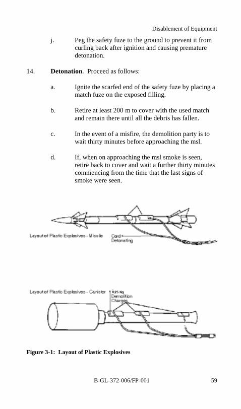
a. Place the required amounts of PE in the positionsshown on figures 3-1.
Javelin S-15 Drill Book
B-GL-372-006/FP-00158
b. Run equal lengths of cord detonating from thecharges and join so that 100 mm of each corddetonating is in contact with the other and there is a300 mm overhang. Knot the charge ends.
c. Securely embed the knotted ends of cord detonatingin the PE and tape it into position.
d. Cut off and discard the first 300 mm of the safetyfuze L1. Cut off the next 300 mm, ignite one endand note the time taken to burn through to the otherend. If the burning time is between 35 and 43seconds inclusive, the fuze remaining on the coilmay be used otherwise the complete coil is to berejected.
e. Establish the time taken to walk to cover (at least200 m away). Double this figure then measure andcut off the required length of safety fuze, minimum600 mm, cutting the end for insertion into thedetonator straight across and the other obliquely(scarfed).
f. Inspect the detonator to ensure there is noobstruction in the cavity. If gently shaking thedetonator does not remove any obstruction thedetonator is to be set aside for destruction. On noaccount is any probe to be used in the open end ofthe detonator.
g. Mark off 23 mm on the straight end of the safetyfuze and insert into the detonator until the mark isjust short of the lip of the cavity. On no account is ascrew motion to be used.
h. Carefully crimp the detonator to the safety fuze at apoint about 5 to 10 mm from the open end of thedetonator.
i. Double the free end of the cord detonating 150 mmfrom the end and tape the detonator to it.
Disablement of Equipment
B-GL-372-006/FP-001 59
j. Peg the safety fuze to the ground to prevent it fromcurling back after ignition and causing prematuredetonation.
14. Detonation. Proceed as follows:
a. Ignite the scarfed end of the safety fuze by placing amatch fuze on the exposed filling.
b. Retire at least 200 m to cover with the used matchand remain there until all the debris has fallen.
c. In the event of a misfire, the demolition party is towait thirty minutes before approaching the msl.
d. If, when on approaching the msl smoke is seen,retire back to cover and wait a further thirty minutescommencing from the time that the last signs ofsmoke were seen.
Figure 3-1: Layout of Plastic Explosives
0.25 Kg
Javelin S-15 Drill Book
B-GL-372-006/FP-001 61
CHAPTER 4CARE AND MAINTENANCE
SERVICING
1. Servicing will be carried out:
a. daily when in use for msl canisters, LML and theAU; and
b. monthly when in storage.
2. Servicing consists of:
a. cleaning the optical assemblies;
b. cleaning the interface connections;
c. cleaning external surfaces of all equipment;
d. checking humidity indicators; and
e. FLTS testing of the AU.
3. Battery maintenance consists of cleaning the terminals.
4. No further servicing, other than that detailed in this chapter isto be carried out by the operator.
5. Careful cleaning of the optics will result in enhancedoperational effectiveness, without risking scratched surfaces thatwould require repair action. It is essential, therefore, that the correctcleaning procedure is strictly adhered to.
6. Examine the interface connections on the AU and ready foruse msl canisters for dampness or dirt. Clean as necessary using aclean, dry cloth and replace the protective covers.
7. Only approved cleaning materials as detailed in this section,are to be used.
Javelin S-15 Drill Book
B-GL-372-006/FP-00162
8. The following precautions are to be taken to ensure the safeand satisfactory cleaning of optical assemblies:
a. ensure that cleaning materials are not contaminatedwith grit, oil, etc.;
b. before wet cleaning, ensure that all loose particles ofgrit or dirt are removed by carefully use of the softhair brush; and
c. do not touch polished optical surfaces with barefingers.
9. The list of approved lens cleaning materials that arecontained in the optical cleaning kit are listed below:
SERIAL DESIGNATION
1 Paper, lens tissue, 10cm X 15cm
2 Methylated spirits (absolute) NSN 6810-21-877-1045or equivalent
3 Brush, mop, no 6
4 Peg wood
CLEANING PROCEDURES
10. Remove grits and dust particles from the optical surface usingthe soft hairbrush.
11. Prepare a swab, using the peg wood wrapped with a lenstissue, and moisten but do not saturate, with Methylated spirits.
12. Using the swab in a light circular motion and starting fromthe centre of the optical surface remove all grease and smears. Finishoff by sliding the swab around the edge to remove any accumulateddirt. Repeat as necessary, using a clean swab until the surface is clean.
13. Dry polish the surface in a similar manner using a dry lenstissue.
Care and Maintenance
B-GL-372-006/FP-001 63
14. To prevent ingress of moisture, the AU battery terminals andsealing ring must be coated with MS4 grease.
15. Clean the outside of the AU, FLTS and ready for use mslcanisters with a clean cloth.
16. Take care to ensure that the equipment is dry before replacingit in the FHC. If the tactical situation does not permit this, theequipment must be dried at the earliest opportunity.
17. Examination of equipment is to be carried out on ready foruse msl canisters and the AU daily, when the tactical situation permits.
VERIFICATIONS
18. There is no requirement for testing the msl in the field. Thechecks constitute a visual examination to verify that the msl canisterhas not been damaged while in storage or transit. Any msl canisterfound to be damaged, or which is suspect in any way, must not befired and is to be set aside for examination by the AmmunitionTechnician or disposal in accordance with SOP's.
19. On each msl canister No. 1 checks to ensure that the:
a. front cover is undamaged and correctly fitted to themsl canister;
b. msl canister forward tube is not fractured ordelaminated;
c. hand locator is securely attached (see note below);
WARNING
Under no circumstances should grease be allowedto come into contact the aiming unit optics.
Javelin S-15 Drill Book
B-GL-372-006/FP-00164
d. forward tube is securely attached to the diaphragmin that the manacle clamp is secure and is in thecorrect position;
e. diaphragm is not fractured;
f. indicator is blue;
g. interface connector is clean and undamaged;
h. rear tube is not dented or cracked and there are noflaws in the metal;
i. expansion cone is not damaged in such a way that itwill obstruct the blow-out panel; and
j. blow-out panel is undamaged and secure.
20. On the AU No. 2 ensures that:
a. the monocular and TX optics are clean andundamaged;
b. the indicator is blue, if not, FCS technician is to beinformed;
c. the outer casing is not damaged;
d. the interface connector is serviceable, i.e., there is nopin misalignment or signs of damage; and
e. the AU/msl canister retaining clip is not damaged orworn; if it is, FCS technician is to be informed.
NOTE
If the hand locator is not secure, exceptional caremust be taken during firing that the operator adoptsthe correct position with is left hand.

Care and Maintenance
B-GL-372-006/FP-001 65
ROLE OF THE FIRST LINE TEST SET
21. Pass/fail testing of AU, LML and the FLTS.
22. The FLTS provides a testing facility for the Javelin AU andLML. The test set, which is used at the user level, is portable and issupplied with one disposable long life lithium battery. Threeinterconnecting cable assemblies are also supplied and used forattachment to the AU and for Built In Test (BIT) purposes.
23. The complete FLTS is contained in a lightweight fieldhandling container; one spare lithium battery, two spare fuses, twospare collimator lamps, test adapter, Beta Light and a specialscrewdriver are also carried in this container. A shipping and storagecontainer carries the FLTS within its field-handling container.
WARNINGRADIATION
The equipment contain a beta lamp light sourcewhich by itself does not produce a significant levelof external radioactivity and no hazard can ariseunless a lamp is broken. In the event of breakage,evacuate and ventilate the immediate area for at leastthirty minutes.
Javelin S-15 Drill Book
B-GL-372-006/FP-00166
24. The test set is essentially an aluminium alloy box comprisingof a cover assembly and mounting plate assembly. The mountingplate houses the display and operator controls. The cover houses alithium battery, connectors, desiccator assembly. A removable adapterplate assembly is also fitted to the front of the FLTS, which providesfor mounting the FLTS onto the AU.
PURPOSE AND FUNCTION
25. To enable the testing of the AU the FLTS is mounted onto theAU and the AU supported on either a test stand or LML. The testscarried out consist of electrical tests on the AU circuitry, checking theguidance system signals and by interaction with the operator, all of thecontrol mechanisms of the system.
26. During the AU test sequence the FLTS informs the operatorvia the display prompt where manual intervention is necessary.
27. The test set-up for the LML is almost identical to that of theAU with exception that there are three msl connections. In this caseeach is connected in turn and the msl selector switch on the sight armassembly operates as part of the test. The FLTS performs a sub-set ofthe AU test sequence to verify the continuity of the cable from thetraverse head.
WARNINGHAZARDOUS MATERIAL
The equipment contains a disposable long life non-chargeable lithium battery. Do not open, puncture,crush or tamper with the battery as this could releaseor expose materials that are potentially flammableand hazardous to the skin and eyes. Do not attemptto charge the lithium battery.
Care and Maintenance
B-GL-372-006/FP-001 67
FLTS CONTROLS AND FUNCTIONS
CONTROLS/INDICATORS
ANDCONNECTORS
DESCRIPTION PURPOSE
TX(Transmitter)
LED (red) Lights when the TX supply isactive
SF (SystemFail)
LED (red) Lights when the system hascatastrophically failed
BL (BatteryLow)
LED (red) Lights when the battery voltageis low
SYS (System) Switch Provides power to the FLTS
TX(Transmitter)
Switch This switch together with twosafety interlock micro-switchesform part of a transmit enablecircuit. This circuit provides aTX supply for the unit under testwhen the micro-switches andthe TX switch are set to ON
Display Sixteencharacterstarburst type,alphanumeric
Used to provide the operatorwith information both in theform of test results and toprompt for his interaction
Keyboard Eight positionkeyboard
Used to select the mode ofoperation and to enable theoperator to communicate withthe system
SL (ShoulderLaunch)
Mode button Initiates the shoulder launch test
LightweightMultipleLauncher
Mode button Initiates the LML test
Javelin S-15 Drill Book
B-GL-372-006/FP-00168
CONTROLS/INDICATORS
ANDCONNECTORS
DESCRIPTION PURPOSE
(LML)
BIT (Built InTest)
Mode button Initiates the Built In Test
DIM (Dimmer) Button When pressed will cause thedisplay to go bright or dim
REC (Recall) Button When pressed will restart thedisplay after a display timeoutor recall the display messagefrom its start
PASS Button This is pressed when a manualtest has been successful
FAIL Button This is pressed when a manualtest has been unsuccessful
CONT(Continue)
Button This button is pressed toconfirm completion of a manualinteraction
SKC(Collimator)
19-pole socket To connect the collimator to theFLTS using collimator harness
SKB (Test) 41-pole socket To connect the FLTS to the AUunder test using test harness
SKK (BIT) 41-pole socket To connect the FLTS BIToutput to the FLTS test harnessusing BIT harness
SKN(Diagnostics)
19-pole socket For use by the manufacturer
SKE (SP) 12-pole socket Not used
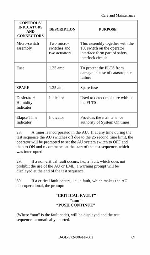
Care and Maintenance
B-GL-372-006/FP-001 69
CONTROLS/INDICATORS
ANDCONNECTORS
DESCRIPTION PURPOSE
Micro-switchassembly
Two micro-switches andtwo actuators
This assembly together with theTX switch on the operatorinterface form part of safetyinterlock circuit
Fuse 1.25 amp To protect the FLTS fromdamage in case of catastrophicfailure
SPARE 1.25 amp Spare fuse
Desicrator/HumidityIndicator
Indicator Used to detect moisture withinthe FLTS
Elapse TimeIndicator
Indicator Provides the maintenanceauthority of System On times
28. A timer is incorporated in the AU. If at any time during thetest sequence the AU switches off due to the 25 second time limit, theoperator will be prompted to set the AU system switch to OFF andthen to ON and recommence at the start of the test sequence, whichwas interrupted.
29. If a non-critical fault occurs, i.e., a fault, which does notprohibit the use of the AU or LML, a warning prompt will bedisplayed at the end of the test sequence.
30. If a critical fault occurs, i.e., a fault, which makes the AUnon-operational, the prompt:
“CRITICAL FAULT”“nnn”
“PUSH CONTINUE”
(Where “nnn” is the fault code), will be displayed and the testsequence automatically aborted.
Javelin S-15 Drill Book
B-GL-372-006/FP-00170
PHYSICAL DATA
31. Dimensions. The dimensions of the FLTS are as follows:
a. Operational—16.5 in (419.1 mm) x 11.4in(289.6 mm) x 11.6 in (294.7 mm).
b. Packaged—20.0 in (508.0 mm) x 18.0 in(472.2 mm) x 14.1 in (358.15 mm).
c. Weight:
(1) operation—10.4 kg; and
(2) packed—18.4 kg.
32. Power Requirement. One disposable long life lithiumbattery fitted to the FLTS and one fitted to the AU in use.
AIMING UNIT TESTING
33. AU tests are to be carried out daily. To ensure that no detailis overlooked, AU testing must be carried out using this drill book.
34. If any test fails, the sequence is to be repeated for verificationand if it again fails an FCS technician is to be informed.
FIRST LINE TEST SET TESTING
35. The Built In Test (BIT) procedure for the FLTS is to becarried out before testing an AU.
PREPARATION FOR TESTS
36. Remove the FLTS from its FHC and:
a. remove the three cable assemblies;
b. ensure that the FLTS system switch is set to OFF;
Care and Maintenance
B-GL-372-006/FP-001 71
c. ensure that the TX switch is set to OFF;
d. fit a lithium battery into the FLTS; and
e. remove the protective caps from the cables andconnect up the FLTS.
FLTS SWITCH ON PROCEDURE
37. Set the FLTS SYS switch to ON; wait, then SELECT MODEshould appear on the FLTS display.
38. At “Switch On” the FLTS performs a Power On Self Test(POST) procedure. Under normal conditions, the first prompt willappear on the display. In the event of a fail condition, the message:
a. ELEC/UNIT FAIL X (1 TO 8); or
b. COLLIMATOR FAIL will be displayed.
39. Set brightness as required using the DIM button.
BUILT IN TEST PROCEDURES
40. If during BIT, “display timeout” occurs (flashing dotdisplayed), press the REC button to recall the display.
41. If any manually requested test fails, press FAIL instead ofPASS. The message ELEC/UNIT FAIL 9 will be displayed.
42. If any automatic procedures fail, the message ELEC/UNITFAIL 9 will be displayed.
NOTE
If POST fails, details of the display are to be notedand FCS informed.

Javelin S-15 Drill Book
B-GL-372-006/FP-00172
43. If BIT fails, details of the display are to be noted and FCSinformed.
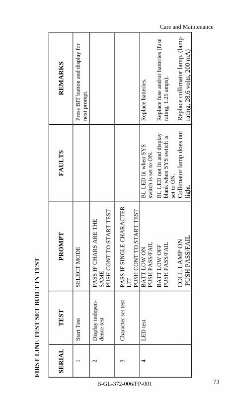
73
FIR
ST L
INE
TEST
SET
BU
ILT
IN T
EST
SER
IAL
TE
STPR
OM
PTFA
UL
TS
RE
MA
RK
S
1St
art T
est
SELE
CT
MO
DE
Pres
s BIT
but
ton
and
disp
lay
for
next
pro
mpt
.
2D
ispl
ay in
depe
n-de
nce
test
PASS
IF C
HA
RS
AR
E TH
ESA
ME
PUSH
CO
NT
TO S
TAR
T TE
ST
3C
hara
cter
set t
est
PASS
IF S
ING
LE C
HA
RA
CTE
RLI
TPU
SH C
ON
T TO
STA
RT
TEST
4LE
D te
stB
ATT
LO
W O
NPU
SH P
ASS
/FA
ILB
L LE
D li
t whe
n SY
Ssw
itch
is se
t to
ON
.R
epla
ce b
atte
ries.
BA
TT L
OW
OFF
PUSH
PA
SS/F
AIL
BL
LED
not
lit a
nd d
ispl
aybl
ank
whe
n SY
S sw
itch
isse
t to
ON
.
Rep
lace
fuse
and
/or b
atte
ries (
fuse
ratin
g, 1
.25
amps
).
CO
LL L
AM
P O
N P
USH
PA
SS/F
AIL
Col
limat
or la
mp
does
not
light
.R
epla
ce c
ollim
ator
lam
p. (l
amp
ratin
g, 2
8.6
volts
, 200
mA
)
Care and Maintenance
B-GL-372-006/FP-001
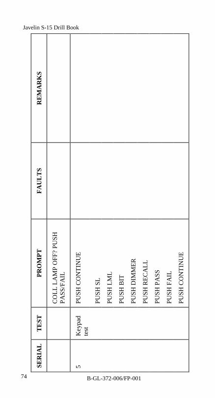
74
SER
IAL
TE
STPR
OM
PTFA
UL
TS
RE
MA
RK
S
CO
LL L
AM
P O
FF?
PUSH
PASS
/FA
IL
5K
eypa
dte
stPU
SH C
ON
TIN
UE
PUSH
SL
PUSH
LM
L
PUSH
BIT
PUSH
DIM
MER
PUSH
REC
ALL
PUSH
PA
SS
PUSH
FA
IL
PUSH
CO
NTI
NU
E
Javelin S-15 Drill Book
B-GL-372-006/FP-001
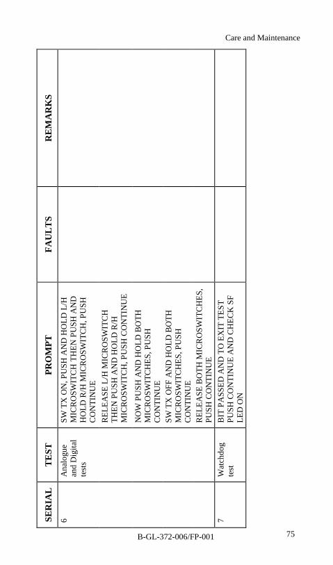
75
SER
IAL
TE
STPR
OM
PTFA
UL
TS
RE
MA
RK
S6
Ana
logu
ean
d D
igita
lte
sts
SW T
X O
N, P
USH
AN
D H
OLD
L/H
MIC
RO
SWIT
CH
TH
EN P
USH
AN
DH
OLD
R/H
MIC
RO
SWIT
CH
, PU
SHC
ON
TIN
UE
REL
EASE
L/H
MIC
RO
SWIT
CH
THEN
PU
SH A
ND
HO
LD R
/HM
ICR
OSW
ITC
H, P
USH
CO
NTI
NU
E
NO
W P
USH
AN
D H
OLD
BO
THM
ICR
OSW
ITC
HES
, PU
SHC
ON
TIN
UE
SW T
X O
FF A
ND
HO
LD B
OTH
MIC
RO
SWIT
CH
ES, P
USH
CO
NTI
NU
ER
ELEA
SE B
OTH
MIC
RO
SWIT
CH
ES,
PUSH
CO
NTI
NU
E7
Wat
chdo
gte
stB
IT P
ASS
ED A
ND
TO
EX
IT T
EST
PUSH
CO
NTI
NU
E A
ND
CH
ECK
SF
LED
ON
Care and Maintenance
B-GL-372-006/FP-001
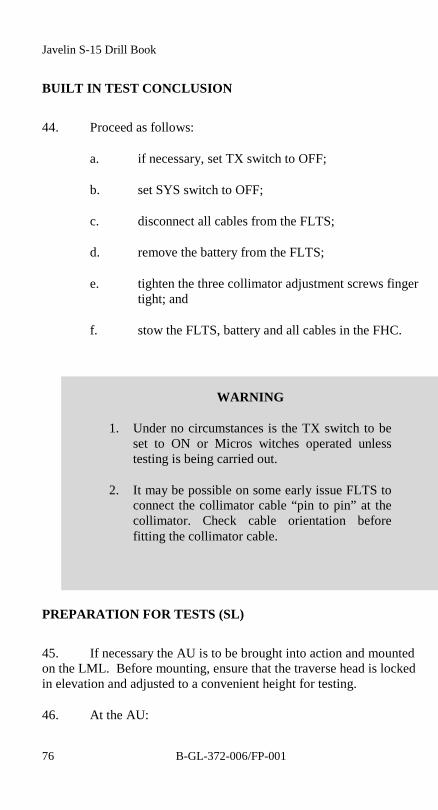
Javelin S-15 Drill Book
B-GL-372-006/FP-00176
BUILT IN TEST CONCLUSION
44. Proceed as follows:
a. if necessary, set TX switch to OFF;
b. set SYS switch to OFF;
c. disconnect all cables from the FLTS;
d. remove the battery from the FLTS;
e. tighten the three collimator adjustment screws fingertight; and
f. stow the FLTS, battery and all cables in the FHC.
PREPARATION FOR TESTS (SL)
45. If necessary the AU is to be brought into action and mountedon the LML. Before mounting, ensure that the traverse head is lockedin elevation and adjusted to a convenient height for testing.
46. At the AU:
WARNING
1. Under no circumstances is the TX switch to beset to ON or Micros witches operated unlesstesting is being carried out.
2. It may be possible on some early issue FLTS toconnect the collimator cable “pin to pin” at thecollimator. Check cable orientation beforefitting the collimator cable.

Care and Maintenance
B-GL-372-006/FP-001 77
a. mount the AU onto the traverse head;
b. remove the cover from the monitor plug P;
c. remove the rubber window cover from the front ofthe guidance head;
d. if necessary fit a lithium battery;
e. ensure that the AU switches are set to the positionsas follows:
SERIAL SWITCH POSITION
1 SYSTEM OFF
2 FUSE MODE 2
3 CROSSWINDCORRECTION
CENTRE
f. fit the Beta Light Assembly into the monocularwindow.
47. If necessary, remove the FLTS, test harness cable andcollimator cable from the FHC.
a. ensure that FLTS SYS and TX switches are set toOFF;
b. if necessary fit the collimator cable (seeWARNING 2, before para 45), and a lithium batteryinto the FLTS;
c. ensure that the FLTS securing bolt is withdrawn;
d. position the FLTS close to the LML stand andconnect the test harness into the monitor plug P onthe AU;
e. mount the FLTS and collimator to the AU;
f. tighten the securing bolt finger tight; and
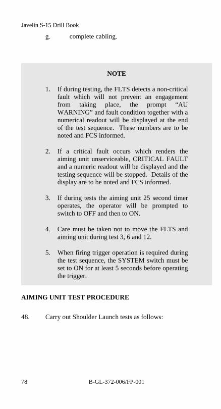
Javelin S-15 Drill Book
B-GL-372-006/FP-00178
g. complete cabling.
AIMING UNIT TEST PROCEDURE
48. Carry out Shoulder Launch tests as follows:
NOTE
1. If during testing, the FLTS detects a non-criticalfault which will not prevent an engagementfrom taking place, the prompt “AUWARNING” and fault condition together with anumerical readout will be displayed at the endof the test sequence. These numbers are to benoted and FCS informed.
2. If a critical fault occurs which renders theaiming unit unserviceable, CRITICAL FAULTand a numeric readout will be displayed and thetesting sequence will be stopped. Details of thedisplay are to be noted and FCS informed.
3. If during tests the aiming unit 25 second timeroperates, the operator will be prompted toswitch to OFF and then to ON.
4. Care must be taken not to move the FLTS andaiming unit during test 3, 6 and 12.
5. When firing trigger operation is required duringthe test sequence, the SYSTEM switch must beset to ON for at least 5 seconds before operatingthe trigger.

79
SER
TEST
PRO
MPT
FAU
LT
SR
EM
AR
KS
1St
art t
est.
SELE
CT
MO
DE
Pres
s SL
butto
n.
ALI
GN
CO
LL T
O A
UX
-WIR
ESA
djus
t by
usin
g th
e th
ree
adju
stm
ent s
crew
s.2
Alig
n co
llim
ator
to A
Ucr
oss w
ires.
PUSH
CO
NTI
NU
E
3R
un u
p at
“Sy
stem
ON
”.A
U b
atte
ries s
yste
msw
itch
DC
-DC
con
verte
rvo
ltage
regu
lato
r.
AU
SW
ON
CR
ITIC
AL
001
AU
pow
ers s
uppl
y fa
ulty
.
TX S
W O
NC
RIT
ICA
L 00
2TX
pow
er m
easu
red
whe
reno
ne sh
ould
be.
CR
ITIC
AL
031
FLTS
TX
switc
h fa
ulty
-vo
ltage
hig
h.
CR
ITIC
AL
032
FLTS
TX
switc
h fa
ulty
-vo
ltage
low
.
Care and Maintenance
B-GL-372-006/FP-001
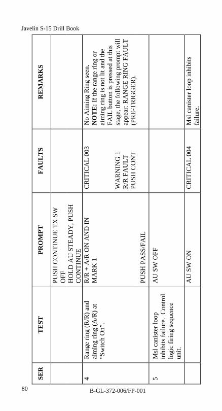
80
SER
TEST
PRO
MPT
FAU
LT
SR
EM
AR
KS
PUSH
CO
NTI
NU
E TX
SW
OFF
HO
LD A
U S
TEA
DY
, PU
SHC
ON
TIN
UE
4R
ange
ring
(R/R
) and
aim
ing
ring
(A/R
) at
“Sw
itch
On”
.
R/R
+ A
/R O
N A
ND
INM
AR
K 1
CR
ITIC
AL
003
WA
RN
ING
1R
/R F
AU
LTPU
SH C
ON
T
No
Aim
ing
Rin
g se
en.
NO
TE: I
f the
rang
e rin
g or
aim
ing
ring
is n
ot li
t and
the
FAIL
but
ton
is p
ress
ed a
t thi
sst
age,
the
follo
win
g pr
ompt
will
appe
ar: R
AN
GE
RIN
G F
AU
LT(P
RE-
TRIG
GER
).PU
SH P
ASS
/FA
IL
5M
sl c
anis
ter l
oop
inhi
bits
failu
re.
Con
trol
logi
c fir
ing
sequ
ence
unit.
AU
SW
OFF
AU
SW
ON
CR
ITIC
AL
004
Msl
can
iste
r loo
p in
hibi
tsfa
ilure
.
Javelin S-15 Drill Book
B-GL-372-006/FP-001

81
SER
TEST
PRO
MPT
FAU
LT
SR
EM
AR
KS
Rel
ease
the
azim
uth
and
elev
atio
n lo
ckin
g bo
lts o
n th
esu
ppor
t hea
d. C
heck
aim
ing
ring
lags
X-w
ires m
ovem
ent.
CR
ITIC
AL
028
Pitc
h of
fset
faul
ty
6R
ate-
aide
d m
ode
test
.Pi
tch,
yaw
inte
rrog
ator
s,ra
te se
nsor
uni
ts, t
orqu
em
otio
ns a
nd a
imin
g rin
g.
MO
VE
AU
UP,
DO
WN
,LE
FT, R
IGH
TA
/R L
AG
S X
-WIR
ESPU
SH P
ASS
/FA
IL
CR
ITIC
AL
029
Yaw
off
set f
aulty
.
HO
LD A
U S
TEA
DY
Inse
rt th
e az
imut
h an
del
evat
ion
lock
ing
bolts
on
the
supp
ort h
ead.
Che
ck th
at th
e ai
min
g rin
gre
turn
s to
its o
rigin
al p
ositi
on.
A/R
CEN
TRES
?
CR
ITIC
AL
027
Cen
tral o
ffse
t fau
lty
PUSH
PA
SS/F
AIL
Care and Maintenance
B-GL-372-006/FP-001

82
SER
TEST
PRO
MPT
FAU
LT
SR
EM
AR
KS
7W
ind
offs
et sw
itch
oper
atio
n. T
rack
ing
elec
troni
cs, w
ind
offs
etya
w to
rque
mot
or a
ndpr
edic
tion
units
.
WIN
D S
W C
ENTR
EC
RIT
ICA
L 00
7W
ind
inpu
t sw
itch
faul
ty.
A/R
IN M
AR
K 1
?W
AR
NIN
G 2
A/R
DR
IFT
FAU
LTPU
SH C
ON
T
Aim
ing
ring
is w
ithin
colli
mat
or M
ark
1 rin
g.Pr
e-IO
F ai
min
g rin
g dr
ift ra
teis
hig
h.
PUSH
PA
SS/F
AIL
WIN
D S
W R
IGH
T
A/R
GO
ES R
IGH
T?A
imin
g rin
g m
oves
to th
e rig
hten
d of
the
AU
X-w
ires.
WIN
D S
W L
EFT
A/R
GO
ES L
EFT?
Aim
ing
ring
mov
es to
the
left
end
of th
e A
U X
-wire
s.
PUSH
PA
SS/F
AIL
Javelin S-15 Drill Book
B-GL-372-006/FP-001

83
SER
TEST
PRO
MPT
FAU
LT
SR
EM
AR
KS
WIN
D S
W C
ENTR
E
A/R
CEN
TRES
?A
imin
g rin
g re
turn
s to
the
cent
re o
f the
AU
X-w
ires.
PUSH
PA
SS/F
AIL
8Jo
ystic
k co
ntro
lpr
e-tri
gger
ope
ratio
n.M
OV
E J/
S U
P, D
OW
N, L
EFT,
RIG
HT
CR
ITIC
AL
008
Pre-
trigg
er jo
ystic
k op
erat
ion
faul
ty.
A/R
CEN
TRES
?C
RIT
ICA
L 00
6Pr
e-tri
gger
AR
doe
s not
lag
X-w
ires n
or re
turn
to c
entre
.
PUSH
PA
SS/F
AIL
95
Seco
nd ti
mer
inhi
bits
pre-
trigg
er.
WA
IT A
UTO
TES
TC
RIT
ICA
L 00
5Pr
e-tri
gger
occ
urs t
oo e
arly
.
NO
TE: T
his p
rom
pt m
ay n
otbe
dis
play
ed.
CR
ITIC
AL
021
FLTS
una
ble
to fo
rce
timeo
utin
hibi
ts.
Care and Maintenance
B-GL-372-006/FP-001
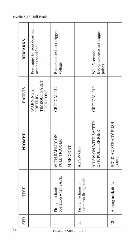
84
SER
TEST
PRO
MPT
FAU
LT
SR
EM
AR
KS
WA
RN
ING
2PR
ETR
IGTI
MEO
UT
FAU
LTPU
SH C
ON
T
Pre-
trigg
er ti
meo
ut d
oes n
otoc
cur a
s spe
cifie
d.
10Fi
ring
mec
hani
smop
erat
ion
whe
n SA
FE.
WIT
H S
AFE
TY O
NPU
LL T
RIG
GER
CR
ITIC
AL
012
Bad
or n
on-e
xist
ent t
rigge
rvo
ltage
.
PUSH
CO
NT
11Fi
ring
mec
hani
smop
erat
ion
firin
g m
ode.
AU
SW
OFF
AU
SW
ON
WIT
H S
AFE
TYO
FF, P
ULL
TR
IGG
ERC
RIT
ICA
L 01
0W
ait 5
seco
nds.
Bad
or n
on-e
xist
ent t
rigge
rpu
lses
.
12A
imin
g m
ark
drift
.H
OLD
AU
STE
AD
Y P
USH
CO
NT
Javelin S-15 Drill Book
B-GL-372-006/FP-001

85
SER
TEST
PRO
MPT
FAU
LT
SR
EM
AR
KS
13Jo
ystic
k co
ntro
l, PO
ST-
trigg
er o
pera
tion.
MO
VE
J/S
UP,
DO
WN
, LEF
T,R
IGH
T.
A/R
STA
BLE
?Jo
ystic
k ha
s no
effe
ct o
n th
epo
sitio
n of
the
aim
ing
ring.
PUSH
PA
SS/F
AIL
CR
ITIC
AL
011
AU
tim
ed o
ut p
ost t
rigge
r and
pre-
IOF.
1425
Sec
onds
tim
er in
hibi
t,PO
ST-tr
igge
r ope
ratio
n,an
d pr
e-IO
F si
gnal
.
WA
IT A
UTO
TES
T
CR
ITIC
AL
030
FLTS
una
ble
to fo
rce
timeo
utin
hibi
ts o
n A
U.
15Po
d ba
ttery
fire
WA
IT A
UTO
TES
TC
RIT
ICA
L 01
3B
ad o
r non
-exi
sten
t pod
fire
puls
e.16
Firs
t sta
ge m
otor
fire
.W
AIT
AU
TO T
EST
17Zo
om ti
me.
WA
IT A
UTO
TES
TC
RIT
ICA
L 01
6B
ad o
r non
-exi
sten
t zoo
mpr
ofile
.
Care and Maintenance
B-GL-372-006/FP-001
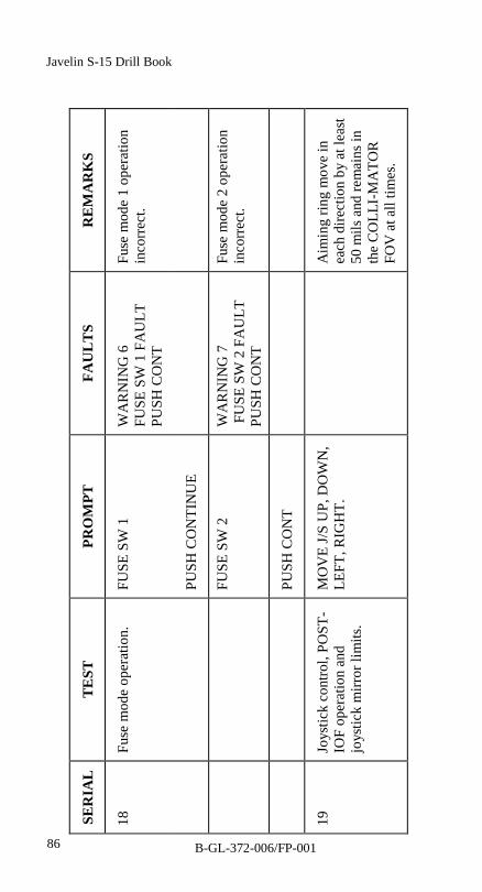
86
SER
IAL
TE
STPR
OM
PTFA
UL
TS
RE
MA
RK
S
18Fu
se m
ode
oper
atio
n.FU
SE S
W 1
WA
RN
ING
6FU
SE S
W 1
FA
ULT
PUSH
CO
NT
Fuse
mod
e 1
oper
atio
nin
corr
ect.
PUSH
CO
NTI
NU
E
FUSE
SW
2W
AR
NIN
G 7
FU
SE S
W 2
FA
ULT
PUSH
CO
NT
Fuse
mod
e 2
oper
atio
nin
corr
ect.
PUSH
CO
NT
19Jo
ystic
k co
ntro
l, PO
ST-
IOF
oper
atio
n an
djo
ystic
k m
irror
lim
its.
MO
VE
J/S
UP,
DO
WN
,LE
FT, R
IGH
T.A
imin
g rin
g m
ove
inea
ch d
irect
ion
by a
t lea
st50
mils
and
rem
ains
inth
e C
OLL
I-M
ATO
RFO
V a
t all
times
.
Javelin S-15 Drill Book
B-GL-372-006/FP-001
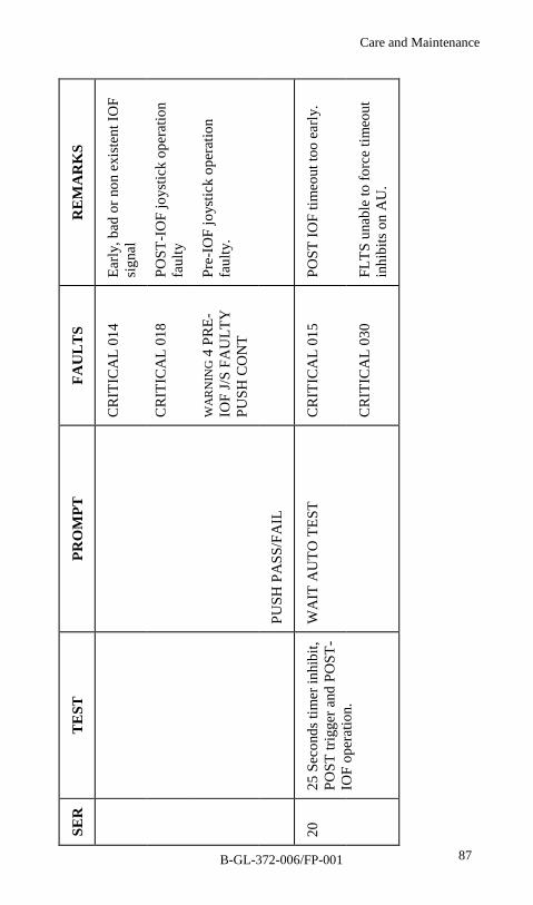
87
SER
TEST
PRO
MPT
FAU
LT
SR
EM
AR
KS
CR
ITIC
AL
014
Early
, bad
or n
on e
xist
ent I
OF
sign
al
CR
ITIC
AL
018
POST
-IO
F jo
ystic
k op
erat
ion
faul
ty
WA
RN
ING
4 P
RE-
IOF
J/S
FAU
LTY
PUSH
CO
NT
Pre-
IOF
joys
tick
oper
atio
nfa
ulty
.
PUSH
PA
SS/F
AIL
CR
ITIC
AL
015
POST
IOF
timeo
ut to
o ea
rly.
2025
Sec
onds
tim
er in
hibi
t,PO
ST tr
igge
r and
PO
ST-
IOF
oper
atio
n.
WA
IT A
UTO
TES
T
CR
ITIC
AL
030
FLTS
una
ble
to fo
rce
timeo
utin
hibi
ts o
n A
U.
Care and Maintenance
B-GL-372-006/FP-001
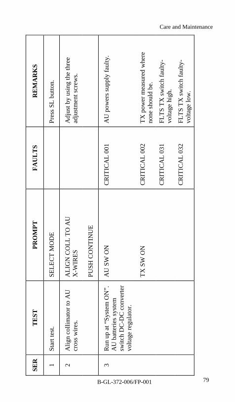
79
SER
TEST
PRO
MPT
FAU
LT
SR
EM
AR
KS
1St
art t
est.
SELE
CT
MO
DE
Pres
s SL
butto
n.
ALI
GN
CO
LL T
O A
UX
-WIR
ESA
djus
t by
usin
g th
e th
ree
adju
stm
ent s
crew
s.2
Alig
n co
llim
ator
to A
Ucr
oss w
ires.
PUSH
CO
NTI
NU
E
3R
un u
p at
“Sy
stem
ON
”.A
U b
atte
ries s
yste
msw
itch
DC
-DC
con
verte
rvo
ltage
regu
lato
r.
AU
SW
ON
CR
ITIC
AL
001
AU
pow
ers s
uppl
y fa
ulty
.
TX S
W O
NC
RIT
ICA
L 00
2TX
pow
er m
easu
red
whe
reno
ne sh
ould
be.
CR
ITIC
AL
031
FLTS
TX
switc
h fa
ulty
-vo
ltage
hig
h.
CR
ITIC
AL
032
FLTS
TX
switc
h fa
ulty
-vo
ltage
low
.
Care and Maintenance
B-GL-372-006/FP-001
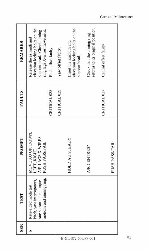
81
SER
TEST
PRO
MPT
FAU
LT
SR
EM
AR
KS
Rel
ease
the
azim
uth
and
elev
atio
n lo
ckin
g bo
lts o
n th
esu
ppor
t hea
d. C
heck
aim
ing
ring
lags
X-w
ires m
ovem
ent.
CR
ITIC
AL
028
Pitc
h of
fset
faul
ty
6R
ate-
aide
d m
ode
test
.Pi
tch,
yaw
inte
rrog
ator
s,ra
te se
nsor
uni
ts, t
orqu
em
otio
ns a
nd a
imin
g rin
g.
MO
VE
AU
UP,
DO
WN
,LE
FT, R
IGH
TA
/R L
AG
S X
-WIR
ESPU
SH P
ASS
/FA
IL
CR
ITIC
AL
029
Yaw
off
set f
aulty
.
HO
LD A
U S
TEA
DY
Inse
rt th
e az
imut
h an
del
evat
ion
lock
ing
bolts
on
the
supp
ort h
ead.
Che
ck th
at th
e ai
min
g rin
gre
turn
s to
its o
rigin
al p
ositi
on.
A/R
CEN
TRES
?
CR
ITIC
AL
027
Cen
tral o
ffse
t fau
lty
PUSH
PA
SS/F
AIL
Care and Maintenance
B-GL-372-006/FP-001
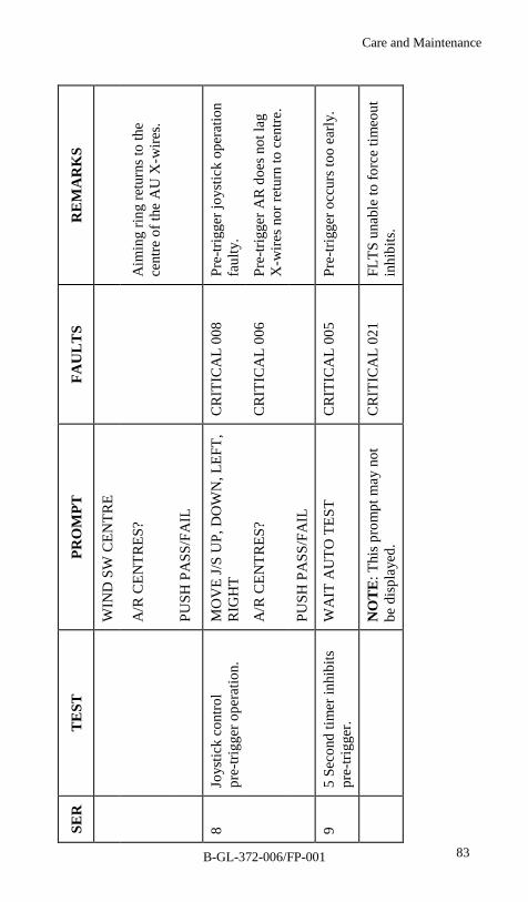
83
SER
TEST
PRO
MPT
FAU
LT
SR
EM
AR
KS
WIN
D S
W C
ENTR
E
A/R
CEN
TRES
?A
imin
g rin
g re
turn
s to
the
cent
re o
f the
AU
X-w
ires.
PUSH
PA
SS/F
AIL
8Jo
ystic
k co
ntro
lpr
e-tri
gger
ope
ratio
n.M
OV
E J/
S U
P, D
OW
N, L
EFT,
RIG
HT
CR
ITIC
AL
008
Pre-
trigg
er jo
ystic
k op
erat
ion
faul
ty.
A/R
CEN
TRES
?C
RIT
ICA
L 00
6Pr
e-tri
gger
AR
doe
s not
lag
X-w
ires n
or re
turn
to c
entre
.
PUSH
PA
SS/F
AIL
95
Seco
nd ti
mer
inhi
bits
pre-
trigg
er.
WA
IT A
UTO
TES
TC
RIT
ICA
L 00
5Pr
e-tri
gger
occ
urs t
oo e
arly
.
NO
TE: T
his p
rom
pt m
ay n
otbe
dis
play
ed.
CR
ITIC
AL
021
FLTS
una
ble
to fo
rce
timeo
utin
hibi
ts.
Care and Maintenance
B-GL-372-006/FP-001
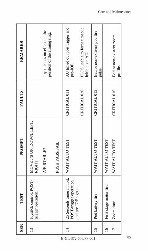
85
SER
TEST
PRO
MPT
FAU
LT
SR
EM
AR
KS
13Jo
ystic
k co
ntro
l, PO
ST-
trigg
er o
pera
tion.
MO
VE
J/S
UP,
DO
WN
, LEF
T,R
IGH
T.
A/R
STA
BLE
?Jo
ystic
k ha
s no
effe
ct o
n th
epo
sitio
n of
the
aim
ing
ring.
PUSH
PA
SS/F
AIL
CR
ITIC
AL
011
AU
tim
ed o
ut p
ost t
rigge
r and
pre-
IOF.
1425
Sec
onds
tim
er in
hibi
t,PO
ST-tr
igge
r ope
ratio
n,an
d pr
e-IO
F si
gnal
.
WA
IT A
UTO
TES
T
CR
ITIC
AL
030
FLTS
una
ble
to fo
rce
timeo
utin
hibi
ts o
n A
U.
15Po
d ba
ttery
fire
WA
IT A
UTO
TES
TC
RIT
ICA
L 01
3B
ad o
r non
-exi
sten
t pod
fire
puls
e.16
Firs
t sta
ge m
otor
fire
.W
AIT
AU
TO T
EST
17Zo
om ti
me.
WA
IT A
UTO
TES
TC
RIT
ICA
L 01
6B
ad o
r non
-exi
sten
t zoo
mpr
ofile
.
Care and Maintenance
B-GL-372-006/FP-001

87
SER
TEST
PRO
MPT
FAU
LT
SR
EM
AR
KS
CR
ITIC
AL
014
Early
, bad
or n
on e
xist
ent I
OF
sign
al
CR
ITIC
AL
018
POST
-IO
F jo
ystic
k op
erat
ion
faul
ty
WA
RN
ING
4 P
RE-
IOF
J/S
FAU
LTY
PUSH
CO
NT
Pre-
IOF
joys
tick
oper
atio
nfa
ulty
.
PUSH
PA
SS/F
AIL
CR
ITIC
AL
015
POST
IOF
timeo
ut to
o ea
rly.
2025
Sec
onds
tim
er in
hibi
t,PO
ST tr
igge
r and
PO
ST-
IOF
oper
atio
n.
WA
IT A
UTO
TES
T
CR
ITIC
AL
030
FLTS
una
ble
to fo
rce
timeo
utin
hibi
ts o
n A
U.
Care and Maintenance
B-GL-372-006/FP-001

88
SER
TEST
PRO
MPT
FAU
LT
SR
EM
AR
KS
WA
RN
ING
5PO
ST IO
F TI
ME
OU
T FA
ULT
PUSH
CO
NT
POST
-IO
F tim
eout
doe
s not
occu
r as s
peci
fied.
21Su
pere
leva
tion
syst
emop
erat
ion.
AU
SW
OFF
Rel
ease
the
elev
atio
n lo
ckin
gbo
lt on
the
supp
ort h
ead.
AU
SW
ON
CR
ITIC
AL
020
Supe
rele
vatio
n op
erat
ion
faul
ty
APP
LY S
-ELE
VD
epre
ss th
eSU
PER
ELEV
ATI
ON
but
ton
and
elev
ate
the
AU
unt
il th
eai
min
g rin
g is
45
mils
dow
n in
the
FOV
of t
he m
onoc
ular
sigh
t(4
5 m
ils d
own
is d
enot
ed b
y th
ebo
ttom
end
of t
he A
U X
-wire
s)
Rel
ease
the
SUPE
REL
EVA
TIO
N b
utto
n.
Javelin S-15 Drill Book
B-GL-372-006/FP-001

89
SER
TEST
PRO
MPT
FAU
LT
SR
EM
AR
KS
WIT
H S
AFE
TY O
FFPU
LL T
RIG
GER
Che
ck th
at th
e ai
min
g rin
gre
mai
ns a
ppro
xim
atel
y 45
mils
dow
n. W
ait 5
seco
nds.
A/R
S-EL
EVD
isen
gage
the
safe
ty c
atch
and
pull
trigg
er.
PUSH
PA
SS/F
AIL
Che
ck th
at th
e ai
min
g rin
gju
mps
to th
e ce
ntre
of t
hecr
oss w
ires a
nd th
en re
turn
s to
its su
per-
elev
ated
pos
ition
inap
prox
imat
ely
2 se
cond
s.22
Win
d of
fset
con
trol,
syst
em o
pera
tion
and
rang
e rin
g of
f tim
e.
AU
SW
OFF
Inse
rt th
e el
evat
ion
bolt
on th
esu
ppor
t hea
d.
AU
SW
ON
CR
ITIC
AL
019
POST
-IO
F w
ind
offs
etop
erat
ion
faul
ty.
Care and Maintenance
B-GL-372-006/FP-001
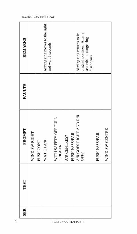
90
SER
TEST
PRO
MPT
FAU
LT
SR
EM
AR
KS
WIN
D S
W R
IGH
T
PUSH
CO
NT
WA
TCH
A/R
Aim
ing
ring
mov
es to
the
right
and
wai
t 5 se
cond
s.
WIT
H S
AFE
TY O
FF P
ULL
TRIG
GER
A/R
CEN
TRES
?
PUSH
PA
SS/F
AIL
A/R
GO
ES R
IGH
T A
ND
R/R
OFF
?A
imin
g rin
g re
turn
s to
itsor
igin
al p
ositi
on.
Afte
r 2se
cond
s the
rang
e rin
gdi
sapp
ears
.
PUSH
PA
SS/F
AIL
WIN
D S
W C
ENTR
E
Javelin S-15 Drill Book
B-GL-372-006/FP-001
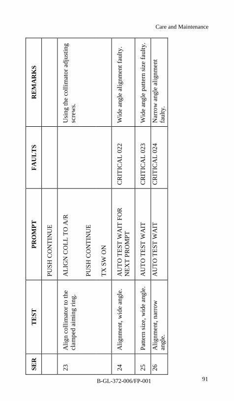
91
SER
TEST
PRO
MPT
FAU
LT
SR
EM
AR
KS
PUSH
CO
NTI
NU
E
23A
lign
colli
mat
or to
the
clam
ped
aim
ing
ring.
ALI
GN
CO
LL T
O A
/RU
sing
the
colli
mat
or a
djus
ting
scre
ws.
PUSH
CO
NTI
NU
E
TX S
W O
N
24A
lignm
ent,
wid
e an
gle.
AU
TO T
EST
WA
IT F
OR
NEX
T PR
OM
PTC
RIT
ICA
L 02
2W
ide
angl
e al
ignm
ent f
aulty
.
25Pa
ttern
size
, wid
e an
gle.
AU
TO T
EST
WA
ITC
RIT
ICA
L 02
3W
ide
angl
e pa
ttern
size
faul
ty.
26A
lignm
ent,
narr
owan
gle.
AU
TO T
EST
WA
ITC
RIT
ICA
L 02
4N
arro
w a
ngle
alig
nmen
tfa
ulty
.
B-GL-372-006/FP-001
Care and Maintenance
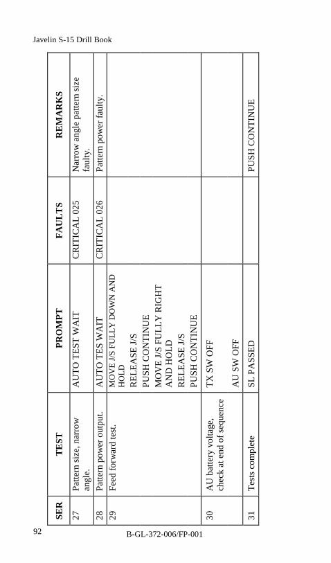
92
SER
TEST
PRO
MPT
FAU
LT
SR
EM
AR
KS
27Pa
ttern
size
, nar
row
angl
e.A
UTO
TES
T W
AIT
CR
ITIC
AL
025
Nar
row
ang
le p
atte
rn si
zefa
ulty
.28
Patte
rn p
ower
out
put.
AU
TO T
ES W
AIT
CR
ITIC
AL
026
Patte
rn p
ower
faul
ty.
29Fe
ed fo
rwar
d te
st.
MO
VE
J/S F
ULL
Y D
OW
N A
ND
HO
LDR
ELEA
SE J/
SPU
SH C
ON
TIN
UE
MO
VE
J/S
FULL
Y R
IGH
TA
ND
HO
LDR
ELEA
SE J/
SPU
SH C
ON
TIN
UE
30A
U b
atte
ry v
olta
ge,
chec
k at
end
of s
eque
nce
TX S
W O
FF
AU
SW
OFF
31Te
sts c
ompl
ete
SL P
ASS
EDPU
SH C
ON
TIN
UE
Javelin S-15 Drill Book
B-GL-372-006/FP-001

Care and Maintenance
B-GL-372-006/FP-001 93
SHOULDER LAUNCH TESTS CONCLUSION
49. Procedure: Proceed as follows:
a. Set the FLTS SYS switch to OFF.
b. Disconnect the test harness from the FLTS and SKAon the AU.
c. Release the securing bolt and remove the FLTS.
d. Disconnect the test harness from the monitor plug Pon the AU.
e. Disconnect the collimator cable from the FLTS.
f. Remove the lithium battery from the FLTS.
g. Tighten the three-collimator adjustment screwsfinger tight.
h. Stow all cable, the battery and the FLTS in theFLTS FHC.
i. Replace the monitor plug cover on the AU.
LIGHTWEIGHT MULTIPLE LAUNCHER TESTS
50. Carry out LML tests as follows:

94
SER
IAL
TE
STPR
OM
PTFA
UL
TR
EM
AR
KS
1Pr
ompt
mod
e.SE
LEC
T M
OD
EO
n FL
TS, p
ress
LM
Lbu
tton.
2LM
L te
st.
CH
ECK
MSL
SEL
On
LML
sele
ctpo
sitio
n 1.
Cor
rect
pos
ition
requ
ired.
SW T
O R
EQ’D
PO
SN
3M
sl c
anis
ter l
oop
test
.PU
SH C
ON
TC
RIT
ICA
L00
4M
sl c
anis
ter l
oop
inhi
bits
failu
re.
TX S
W O
FFC
RIT
ICA
L03
1FL
TS T
X sw
itch
faul
ty–
volta
ge h
igh.
AU
SW
ON
CR
ITIC
AL
001
AU
pow
er s
uppl
yfa
ulty
.PU
SH C
ON
TIN
UE
AU
SW
OFF
Javelin S-15 Drill Book
B-GL-372-006/FP-001
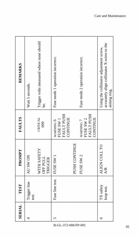
95
SER
IAL
TE
STPR
OM
PTFA
UL
TS
RE
MA
RK
S
4Tr
igge
r lin
ete
st.
AU
SW
ON
Wai
t 5 se
cond
s.
WIT
H S
AFE
TYO
FF P
ULL
TRIG
GER
CR
ITIC
AL
009
Trig
ger v
olts
mea
sure
d w
here
non
e sh
ould
be.
5Fu
se li
ne te
st.
FUSE
SW
1W
AR
NIN
G 6
FUSE
SW
1FA
ULT
PU
SHC
ON
TIN
UE
Fuse
mod
e 1
oper
atio
n in
corr
ect.
PUSH
CO
NTI
NU
E
FUSE
SW
2W
AR
NIN
G 7
FUSE
SW
2FA
ULT
PU
SHC
ON
TIN
UE
Fuse
mod
e 2
oper
atio
n in
corr
ect.
6TX
safe
tylo
op te
st.
ALI
GN
CO
LL T
OA
/RU
sing
the
colli
mat
or a
djus
tmen
t scr
ew,
accu
rate
ly a
lign
colli
mat
or X
-wire
s to
the
aim
ing
ring.
Care and Maintenance
B-GL-372-006/FP-001
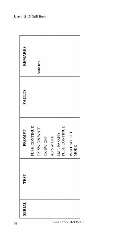
96
SER
IAL
TE
STPR
OM
PTFA
UL
TS
RE
MA
RK
S
PUSH
CO
NTI
NU
E
TX S
W O
N W
AIT
Aut
o te
st.
TX S
W O
FF
AU
SW
OFF
LML
PASS
EDPU
SH C
ON
TIN
UE
WA
IT S
ELEC
TM
OD
E
B-GL-372-006/FP-001
Javelin S-15 Drill Book
Care and Maintenance
B-GL-372-006/FP-001 97
LIGHTWEIGHT MULTIPLE LAUNCHER TESTSCONCLUSION
51. Procedure. Proceed as follows:
a. Set the FLTS SYS switch to OFF.
b. Disconnect the test harness from the FLTS.
c. Release the securing bolt and remove the FLTS.
d. Disconnect the test harness from the LML and AU.
e. Disconnect the collimator cable from the FLTS.
f. Remove the lithium battery from the FLTS.
g. Tighten the three collimator adjustment screwsfinger tight.
h. Stow all cables, battery and FLTS in the FLTS FHC.
i. Fit the monitor plug P cover on the AU.
AIMING UNIT STABILIZATION TEST
52. Carry out the stabilization test as follows:
NOTE
1. These tests are to be repeated at each position ofthe LML MISSILE SELECT switch.
2. When changing the position of the LMLSELECT switch ensure that the test harnesscable is connected to the appropriate chute.
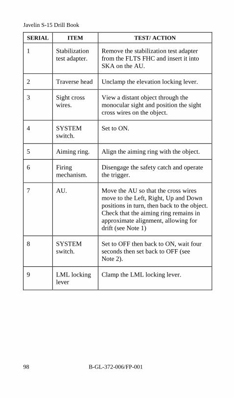
Javelin S-15 Drill Book
B-GL-372-006/FP-00198
SERIAL ITEM TEST/ ACTION
1 Stabilizationtest adapter.
Remove the stabilization test adapterfrom the FLTS FHC and insert it intoSKA on the AU.
2 Traverse head Unclamp the elevation locking lever.
3 Sight crosswires.
View a distant object through themonocular sight and position the sightcross wires on the object.
4 SYSTEMswitch.
Set to ON.
5 Aiming ring. Align the aiming ring with the object.
6 Firingmechanism.
Disengage the safety catch and operatethe trigger.
7 AU. Move the AU so that the cross wiresmove to the Left, Right, Up and Downpositions in turn, then back to the object.Check that the aiming ring remains inapproximate alignment, allowing fordrift (see Note 1)
8 SYSTEMswitch.
Set to OFF then back to ON, wait fourseconds then set back to OFF (seeNote 2).
9 LML lockinglever
Clamp the LML locking lever.
Care and Maintenance
B-GL-372-006/FP-001 99
AIMING UNIT STABILIZATION TEST CONCLUSION
53. Procedure. Proceed as follows:
a. Remove the Beta Light assembly from the AU andstabilization test adapter from SKB LML chute 1,and stow them in the FLTS FHC.
b. If necessary replace the AU battery.
c. Carry out the load or cease firing drills(see Chapter 2).
ANTI-ICING PROCEDURE
54. The equipment should be protected as much as possible fromexposure to freezing rain or mist. Anti-icing procedures must becarried out when the ambient temperature falls below 0o C and:
a. exposure is unavoidable, all AUs and msl canistersimmediately prior to mating the weapon systems;
b. before repackaging after use, on all AUs, mslcanisters and FHC; and
NOTE
1. The amount of drift should not exceed 45 milsin 10 seconds (45 mils is the distance from thecentre to the ends of the cross wires).
2. Setting the SYSTEM switch to ON for 4seconds, allow the TX zoom lens to reset.
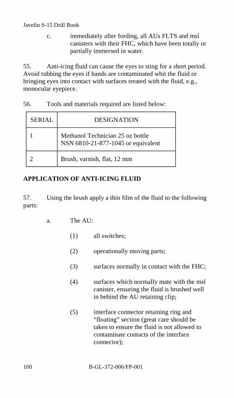
Javelin S-15 Drill Book
B-GL-372-006/FP-001100
c. immediately after fording, all AUs FLTS and mslcanisters with their FHC, which have been totally orpartially immersed in water.
55. Anti-icing fluid can cause the eyes to sting for a short period.Avoid rubbing the eyes if hands are contaminated whit the fluid orbringing eyes into contact with surfaces treated with the fluid, e.g.,monocular eyepiece.
56. Tools and materials required are listed below:
SERIAL DESIGNATION
1 Methanol Technician 25 oz bottleNSN 6810-21-877-1045 or equivalent
2 Brush, varnish, flat, 12 mm
APPLICATION OF ANTI-ICING FLUID
57. Using the brush apply a thin film of the fluid to the followingparts:
a. The AU:
(1) all switches;
(2) operationally moving parts;
(3) surfaces normally in contact with the FHC;
(4) surfaces which normally mate with the mslcanister, ensuring the fluid is brushed wellin behind the AU retaining clip;
(5) interface connector retaining ring and“floating” section (great care should betaken to ensure the fluid is not allowed tocontaminate contacts of the interfaceconnector);
Care and Maintenance
B-GL-372-006/FP-001 101
(6) monocular eyepiece rubber; and
(7) surfaces of batteries that come into contactwith the battery box, taking care that fluiddoes not contaminate battery contacts andscrews.
b. The msl canister:
(1) pressure equalizing valve;
(2) msl canister forward tube and joint betweenfront end cover and tube;
(3) surfaces normally in contact with the FHC;
(4) surfaces which normally mate with the AU,paying particular attention to the AUattachment saddle cut out; and
(5) blow out panel.
c. The FLTS:
(1) keyboard/display and switches;
(2) surfaces normally in contact with the FHC;and
(3) surfaces which normally mate with the AU.
d. Drain any residual water from the AU, msl canisterand FHC. Using a brush apply a thin film of thefluid to the following parts:
(1) parts of the container normally in contactwith the AU;
(2) mating surfaces of both halves of thecontainer; and
(3) securing straps and fasteners.
Javelin S-15 Drill Book
B-GL-372-006/FP-001102
58. For the optics proceed as follows:
a. Prepare a swab, using the peg wood wrapped withpaper lens tissue and moistened (NOTSATURATED) with Methylated spirit.
b. Using a light circular motion from the centre of theoptical surface outward, moisten the iced surfacewith Methylated spirit. Repeat as necessary using aclean swab each time until the ice is completelyremoved and the surface is perfectly clean.
c. Lightly polish the surface in a similar manner usinga clean dry paper tissue.
d. Prevent further icing by avoiding breathing ontooptical surfaces.
NOTE
When the FHC are closed, do not stow the free endsof the securing loops. This will assist in opening thecontainer if ice forms on the straps.
WARNING
Damage could result and performance be degradedif anti-icing fluid is allowed to contaminate theoptical surfaces. Before operating AUs which havebeen treated with anti-icing fluid, all optics must bewiped clean in accordance with this chapter, toremove any fluid or ice which may have formed.The rubber eye shield on the monocular must bewiped with a clean cloth, to prevent any trace of thefluid affecting the eyes.