Embed Size (px)
Citation preview
i
DESIGN OF A THREE PHASE FOUR QUADRANT VARIABLE
SPEED DRIVE FOR PERMANENT MAGNET BRUSHLESS DC
MOTORS
JONAS DON-YELEE DAKORA
Student Number: 21242393
A thesis submitted in fulfilment of the requirements for the
Master of Engineering Degree
in the
Faculty of Engineering and the Built Environment
Department of Electronic Engineering
Durban University of Technology
I undertake that all the material presented in this thesis is my own work and has not been written
for me, in whole or in part by any other person. I undertake that any quotation or paraphrase
from the published or unpublished work of another person has been duly acknowledged in the
work which I now present for examination.
__________________________
Student: Jonas Don-yelee Dakora
Approved for Final Submission
________________________ _______________________
Supervisor: Dr. Poobalan Govender Co-Supervisor: Mr. Nelendran Pillay
Durban, 25 February 2016

ii
ACKNOWLEDGEMENTS
I would like to thank my supervisor, Dr Poobalan Govender and my co-supervisor, Nelendran
Pillay for their academic, encouragement and enthusiasm to complete this project. Thanks to
them for all their motivation, suggestions and corrections.
Thank you to the Department of Electronic Engineering at Durban University of Technology for
the financial support and an office with all hour’s access. The financial assistance of the Centre
for Research Management and Development at the Durban University of Technology is hereby
acknowledged.
I also wish to express my sincere appreciation to the Optimization and Energy Studies Group at
the Durban University of Technology for the use of the post graduate control system laboratory.

iii
DEDICATION
This thesis is dedicated to my son, Benedict Dakora and my brother, Samuel Dakora. May you
live to fulfill the destiny of the Tampaa Dakora family. God richly bless you.
iv
ABSTRACT
The aim of this research project is to design a three phase four quadrant variable speed drive
(VSD) for a permanent magnet brushless direct current motor (PMBLDC) that can be applied to
an electric bicycle (e-bike). The design is confined to PMBLDC motors with a maximum power
rating of 1.5kW. The speed controller operates in current mode at a maximum voltage and
current rating of 50V and 30A, respectively. The VSD has the ability to smoothly control the
current delivered to the DC motor and therefore controls its torque. The motor’s current is
limited in all four quadrants of operation, and its speed is limited in the forward and reverse
directions. The performance of the proposed DC motor VSD system is tested on an electric-
bicycle.
The PMBLDC motor has three hall sensors embedded into the stator to determine rotor
position. A phase switcher module interprets the position signals and produces a switching
pattern. This effectively transforms the BLDC motor into a direct current (DC) brushed motor.
The unipolar switching scheme used ensures that current flows out of the battery only for
motoring operation and into the battery during regenerative braking. The current and torque are
directly proportional in a BLDC motor. Torque control is achieved in the BLDC motor using a
single channel current controller. The phase switcher current is monitored and used to control the
duty cycle of the synchronous converter switches.
The proposed e-bike speed control system provides efficient control in all four quadrants of
operation and it is a suitable alternative for a low cost transportation mode.
v
TABLE OF CONTENTS
ACKNOWLEDGEMENTS ......................................................................................................... ii
DEDICATION ............................................................................................................................. iii
ABSTRACT .................................................................................................................................. iv
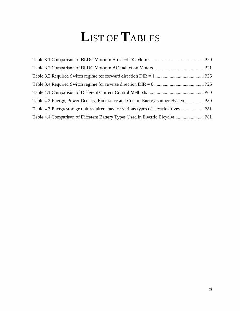
LIST OF TABLES ....................................................................................................................... xi
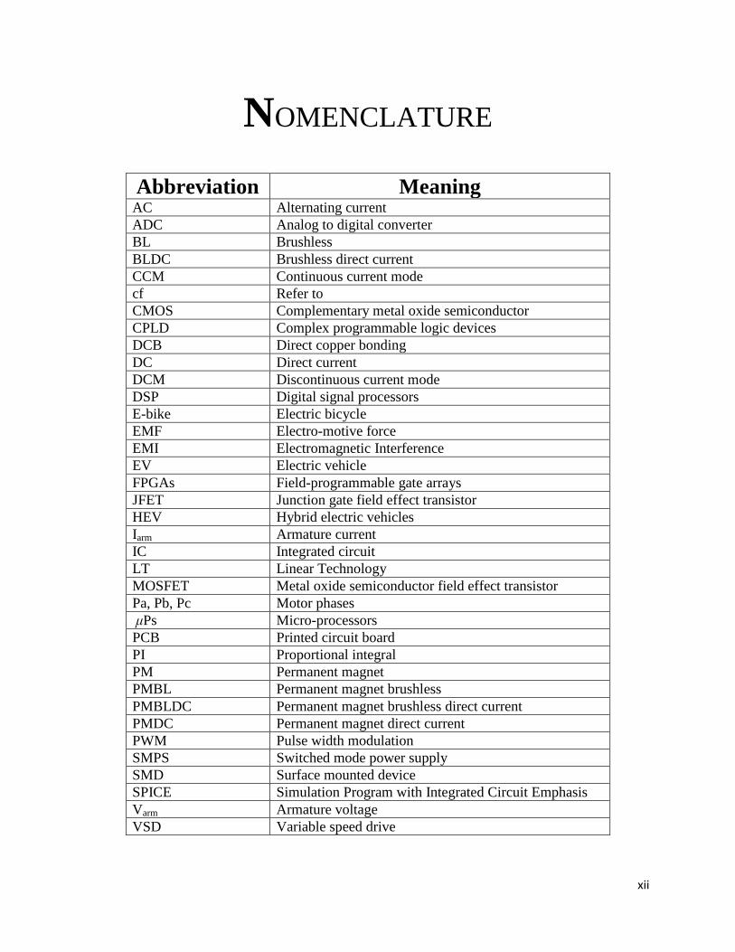
NOMENCLATURE .................................................................................................................... xii
CIRCUIT NOMENCLATURE ................................................................................................ xiii
CHAPTER 1: INTRODUCTION
1.1 BACKGROUND TO RESEARCH .............................................................................................. 1
1.2 RESEARCH PROBLEM .............................................................................................................. 3
1.3 RESEARCH AIM AND OBJECTIVE ......................................................................................... 3
1.4 SCOPE OF RESEARCH .............................................................................................................. 4
1.5 CONTRIBUTION OF THE STUDY ........................................................................................... 5
1.6 STRUCTURE OF THE THESIS .................................................................................................. 5
CHAPTER 2: LITERATURE REVIEW
2.1 INTRODUCTION ........................................................................................................................ 7
2.2 CONTROLLERS WITH DIFFERENT TECHNIQUES .............................................................. 7
2.2.1 3-Phase BLDC motor control with quadrature encoder using 56F800/E ............................ 8
2.2.2 Electric bike BLDC hub motor control using the Z8FMC1600 MCU .................................. 9
2.2.3 Current control of brushless DC motor based on a common DC signal for space operated
vehicles………………………………………………………………………………………………………………………………………….10
2.2.4 Design of permanent magnet brushless DC motor control system based on the
dsPIC30F4012 .................................................................................................................................... 10
2.2.5 A hybrid controller for the speed control of a permanent magnet synchronous motor drive
……………………………………………………………………………………………………………………………………….11
2.2.6 Super-capacitor/battery hybrid powered electric bicycle via a smart boost converter ...... 11
2.2.7 Simplified sensorless control for BLDC motor, using DSP technology .............................. 12
2.3 SUMMARY AND CONCLUSIONS ......................................................................................... 13
CHAPTER 3: PMBLDC MOTOR DESIGN AND DRIVE CONTROL
3.1 DESIGN OF A PMBLDC MOTOR ........................................................................................... 15
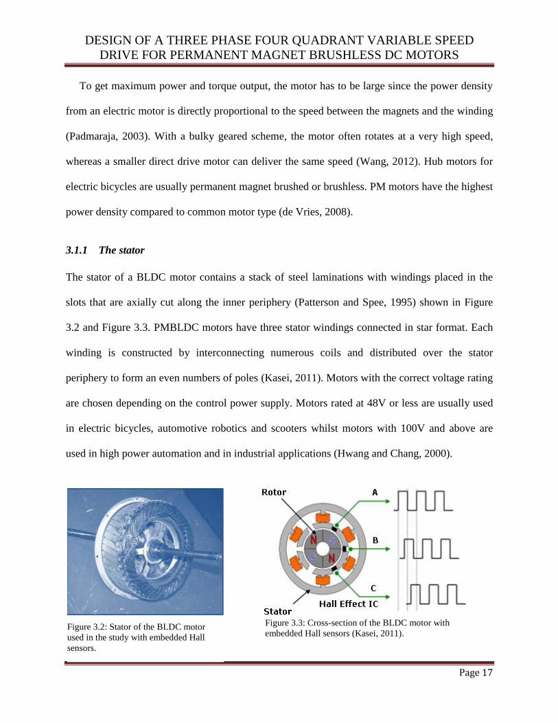
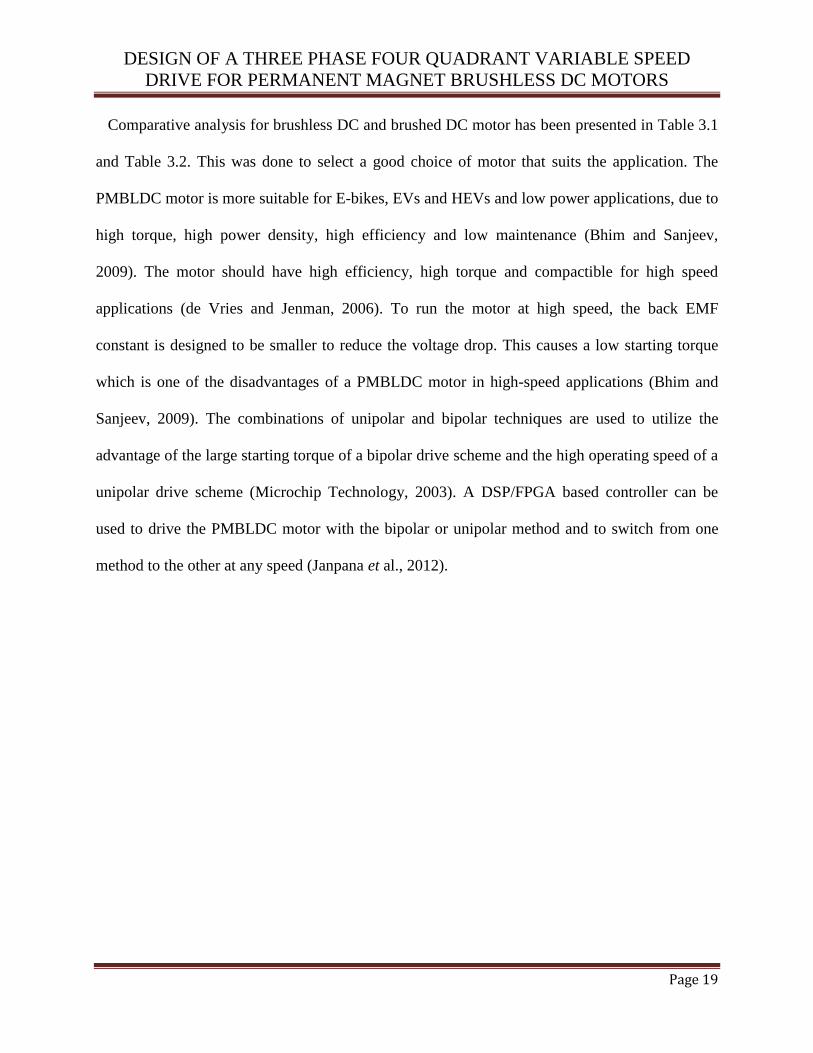
3.1.1 The stator ............................................................................................................................ 17
vi
3.1.1 The rotor ............................................................................................................................. 18
3.2 POWERING OF A PMBLDC MOTOR ..................................................................................... 21
3.2.1 Commutation ....................................................................................................................... 24
3.2.2 Back EMF ........................................................................................................................... 29
3.2.3 Torque ................................................................................................................................. 30
3.2.4 Speed control ...................................................................................................................... 30
3.2.5 Power efficiency .................................................................................................................. 31
3.3 DC-DC LEVEL SHIFTER OPERATION .................................................................................. 32
3.3.1 Boost converter ................................................................................................................... 32
3.3.2 Two quadrant operation ...................................................................................................... 34
3.4 SUMMARY AND CONCLUSIONS ......................................................................................... 38
CHAPTER 4: HARDWARE DESIGN FOR THE PROPOSED
4-QUADRANT VARIABLE SPEED DRIVE
4.1 INTRODUCTION ...................................................................................................................... 40
4.2 FOUR QUADRANT OPERATION ........................................................................................... 40
4.3 DESIGN OF THE PROPOSED VSD SYSTEM ........................................................................ 46
4.3.1 Three phase switcher design ............................................................................................... 47
4.3.2 Power MOSFET drivers ...................................................................................................... 49
4.3.3 Protection logic control ...................................................................................................... 51
4.3.4 The ATMEGA328 Microcontroller ..................................................................................... 52
4.3.5 Pulse width modulation ....................................................................................................... 55
4.3.6 Current controller ............................................................................................................... 59
4.3.7 Temperature control ........................................................................................................... 68
4.3.8 Speed limitation................................................................................................................... 70
4.3.9 Power supply design ........................................................................................................... 72
4.3.10 Regenerative braking .......................................................................................................... 74
4.3.11 Energy storage system ........................................................................................................ 79
4.3.12 Thermal design .................................................................................................................... 82
4.4 SUMMARY AND CONCLUSIONS ......................................................................................... 87
CHAPTER 5: SIMULATION STUDIES
5.1 INTRODUCTION ...................................................................................................................... 89
vii
5.2 VOLTAGE AND CURRENT CONTROL ................................................................................. 89
5.3 SUMMARY AND CONCLUSIONS ......................................................................................... 94
CHAPTER 6: LIVE TEST RESULTS
6.1 INTRODUCTION AND EXPERIMENT SETUP ..................................................................... 96
6.2 EXPERIMENTAL RESULTS .................................................................................................... 98
6.3 ANALYSIS OF RESULTS AND DISCUSSION .................................................................... 107
6.3.1 Speed and torque measurements ....................................................................................... 108
6.3.2 Current commutation ........................................................................................................ 109
6.3.3 PWM and frequency control ............................................................................................. 111
6.3.4 Motoring mode .................................................................................................................. 112
6.3.5 Generating mode ............................................................................................................... 112
6.3.6 Forward/Reverse control .................................................................................................. 113
6.3.7 Limitation and protection .................................................................................................. 114
6.4 SUMMARY AND CONCLUSIONS ....................................................................................... 114
CHAPTER 7: SUMMARY OF STUDY, CONCLUSIONS AND RECOMMENDATIONS
7.1 SUMMARY AND CONCLUSIONS ....................................................................................... 116
7.2 RECOMMENDATIONS .......................................................................................................... 119
REFERENCES .......................................................................................................................... 121
APPENDIX A: CONTROLLER SCHEMATIC ................................................................... 127
APPENDIX B: SOFTWARE CODE ...................................................................................... 128
APPENDIX C: BLDC MOTOR DATASHEET .................................................................... 135
APPENDIX D: BATTERY DATASHEET ............................................................................. 137
APPENDIX E: CONTROLLER MOUNTED ON E-bike .................................................... 138
APPENDIX F: Summary of electric bicycle manufacturers and respective models (Ev-Info,
2014) ........................................................................................................................................... 139
viii
LIST OF FIGURES
Figure 3.1 BLDC Motor Transverse Section .......................................................................... P16
Figure 3.2 Stator of a BLDC Motor ........................................................................................ P17
Figure 3.3 Cross section of a BLDC Motor with embedded hall sensors ............................... P17
Figure 3.4 Brushless-Type DC Motor ..................................................................................... P18
Figure 3.5 The rotor of a PMBLDC Motor ............................................................................. P18
Figure 3.6 DC VSD System .................................................................................................... P22
Figure 3.7 A typical 3-phase MOSFET power stage and its 6 switched voltage vectors ....... P23
Figure 3.8 SPICE simulated phase voltages switched to a 3-phase PMBLDC motor ............ P23
Figure 3.9 SPICE simulated PWM switching signals for power MOSFET drivers ............... P24
Figure 3.10 Stator Flux Vectors at Six-Step Control .............................................................. P25
Figure 3.11 Rotor position at [110] ......................................................................................... P25
Figure 3.12 Forward Direction ................................................................................................ P27
Figure 3.13 Reverse Direction ................................................................................................ P27
Figure 3.14 Phase Voltages with Hall Sensors at 120° ........................................................... P28
Figure 3.15 Circuit diagram of a Boost Converter .................................................................. P34
Figure 3.16 Voltage and Current waveforms of a Boost Converter........................................ P34
Figure 3.17 Two quadrant of motor operation in bold ............................................................ P35
Figure 2.18 Half Bridge Circuit Configuration for two quadrant operation ........................... P36
Figure 3.19 Forward motoring when Q1 is conducting ........................................................... P37
Figure 3.20 Regeneration when D1 is conducting ................................................................... P37
Figure 3.21 Output Voltage and Current Waveforms of the H-Bridge Circuit....................... P38
Figure 4.1 The Four Quadrants of motor operation ................................................................ P41
Figure 4.2 Full Bridge Configuration with Positive current ................................................... P44
Figure 4.3 Full Bridge Configuration with Negative current .................................................. P45
Figure 4.4 Four quadrant Bipolar switching scheme .............................................................. P45
Figure 4.5 VBUS and ILOAD of Unipolar switching scheme ...................................................... P46
Figure 4.6 Four Quadrant Control System .............................................................................. P47
ix
Figure 4.7 Phase Switcher Block Diagram ............................................................................. P48
Figure 4.8 GWM100-01X1 – full bridge phase switcher........................................................ P48
Figure 4.9 Schematic diagram of LM5101 ............................................................................. P50
Figure 4.10 Half Bridge LM5101 MOSFET Driver Circuit ................................................... P51
Figure 4.11 Protection Logic Control with Dead Time .......................................................... P52
Figure 4.12 ATMEGA328 microcontroller for the logic control............................................ P53
Figure 4.13 Flowchart for the controller ................................................................................. P54
Figure 4.14 Logic Control for Forward/Reverse ..................................................................... P55
Figure 4.15 Pulse Width Modulation Control Circuit ............................................................. P58
Figure 4.16 Current Sense Filter ............................................................................................. P63
Figure 4.17 Current Amplifier ................................................................................................ P65
Figure 4.18 Current source half bridge connected to the power stage .................................... P66
Figure 4.19 Current Controller Half Bridge Circuit ................................................................ P67
Figure 4.20 The temperature cut out circuit ............................................................................ P69
Figure 4.21 The LM2917 circuit ............................................................................................. P71
Figure 4.22 LM2576 Voltage Regulator ................................................................................. P73
Figure 4.23 5V Supply using LM7805 Voltage Regulator ..................................................... P74
Figure 4.24 Regenerative Braking Power Status Circuit ........................................................ P77
Figure 4.25 Conventional Boost Converter for Regenerative Braking ................................... P77
Figure 5.1 Motor current (green) resulting from six-step commutation ................................. P90
Figure 5.2 The DC bus voltage (green) and the average voltage (red) at 25kHz PWM ......... P91
Figure 5.3 The BLDC voltage (red) and the average phase current (blue) ............................. P92
Figure 5.4 Instantaneous power converted through the back EMF......................................... P93
Figure 5.5 Power output (red) at maximum speed with constant power dissipation (black) .. P93
Figure 6.1 Test bench .............................................................................................................. P97
Figure 6.2 Measured and Simulated high side phase voltage at 500rpm ............................... P98
Figure 6.3 Measured and Simulated low side phase voltage at 500rpm ................................. P99
Figure 6.4a Simulated high side PWM output for each phase .............................................. P100
Figure 6.4b Measured high side PWM output for each phase .............................................. P100
Figure 6.5a Simulated phase current at 500rpm .................................................................... P101
Figure 6.5b Measured phase current at 200rpm .................................................................... P102
x
Figure 6.6 Simulated current for torque control at 500rpm .................................................. P102
Figure 6.7 Measured resistor current…............................................................................. …P103
Figure 6.8 Measured phase current (blue) and voltage (red) ................................................ P103
Figure 6.9 Discharging of the battery when motor is in use ................................................. P104
Figure 6.10 Charging of the battery using regenerative braking ........................................... P104
Figure 6.11 Regenerative braking at 24V ............................................................................. P104
Figure 6.12 Battery voltage which is limited at 36V ............................................................ P105
Figure 6.13 Torque versus current characteristic .................................................................. P105
Figure 6.14 Speed versus voltage characteristic ................................................................... P106
Figure 6.15 Torque versus Speed characteristic.................................................................... P106
xi
LIST OF TABLES
Table 3.1 Comparison of BLDC Motor to Brushed DC Motor .............................................. P20
Table 3.2 Comparison of BLDC Motor to AC Induction Motors ........................................... P21
Table 3.3 Required Switch regime for forward direction DIR = 1 ......................................... P26
Table 3.4 Required Switch regime for reverse direction DIR = 0 .......................................... P26
Table 4.1 Comparison of Different Current Control Methods ................................................ P60
Table 4.2 Energy, Power Density, Endurance and Cost of Energy storage System ............... P80
Table 4.3 Energy storage unit requirements for various types of electric drives .................... P81
Table 4.4 Comparison of Different Battery Types Used in Electric Bicycles ........................ P81
xii
NOMENCLATURE
Abbreviation Meaning AC Alternating current
ADC Analog to digital converter
BL Brushless
BLDC Brushless direct current
CCM Continuous current mode
cf Refer to
CMOS Complementary metal oxide semiconductor
CPLD Complex programmable logic devices
DCB Direct copper bonding
DC Direct current
DCM Discontinuous current mode
DSP Digital signal processors
E-bike Electric bicycle
EMF Electro-motive force
EMI Electromagnetic Interference
EV Electric vehicle
FPGAs Field-programmable gate arrays
JFET Junction gate field effect transistor
HEV Hybrid electric vehicles
Iarm Armature current
IC Integrated circuit
LT Linear Technology
MOSFET Metal oxide semiconductor field effect transistor
Pa, Pb, Pc Motor phases
μPs Micro-processors
PCB Printed circuit board
PI Proportional integral
PM Permanent magnet
PMBL Permanent magnet brushless
PMBLDC Permanent magnet brushless direct current
PMDC Permanent magnet direct current
PWM Pulse width modulation
SMPS Switched mode power supply
SMD Surface mounted device
SPICE Simulation Program with Integrated Circuit Emphasis
Varm Armature voltage
VSD Variable speed drive

xiii
CIRCUIT NOMENCLATURE
Abbreviation Meaning AH High output side for phase A
AL Low output side for phase A
GND Ground
HINA High input for phase A
LINA Low input for phase A
HS1 Hall sensor 1
HS2 Hall sensor 2
HS3 Hall sensor 3
Ibldc BLDC motor current
Vbus Battery voltage
DESIGN OF A THREE PHASE FOUR QUADRANT VARIABLE SPEED
DRIVE FOR PERMANENT MAGNET BRUSHLESS DC MOTORS
Page 1
CHAPTER1
INTRODUCTION
1.1 BACKGROUND TO RESEARCH
With a fast developing world, we have reached a point where efficient and sustainable solutions
need to be found to address the issues of transport, pollution, traffic congestion, cost of fuel,
cars’ high maintenance and insurance cost. Electric drives offer huge potential for energy
conservation in transportation. While efforts to introduce commercially-viable Electric Vehicles
(EV) continue with progress in battery and fuel cell technologies, hybrid electric vehicles (HEV)
are sure to make a huge impact (Teahyung et al., 2006). HEV’s offer fewer generated emissions
and better energy efficiency than internal combustion engine vehicles, making them desirable to
implement (Thompson, 2008). Considering the high fuel prices and carbon dioxide emissions,
electric bicycles (E-bike), electric vehicles (EV) and motor cycles are some of the potential
technologies for three phase four quadrant variable speed drives to improve the lives of people.
Electric bicycles in China and India have already demonstrated the ability to offer an inexpensive
way to travel the short distances covered in urban areas.
VSD technology spans virtually the entire industrial revolution, from the development of the
steam engine to modern microprocessor based electronic motor controllers (George and William,
2000). Refinements of this technology have being fuelled in recent years by improved reliability

DESIGN OF A THREE PHASE FOUR QUADRANT VARIABLE SPEED
DRIVE FOR PERMANENT MAGNET BRUSHLESS DC MOTORS
Page 2
and performance of electronic devices and are occurring at a more rapid pace than ever, resulting
in greater performance at low cost (Komatsu et al., 2010). EVs used as urban commuting
vehicles are one way of providing the same level of transportation while eliminating the urban
hazardous gas emissions, thus maintaining the standard of life without compromising the
environment.
Given the above-mentioned shortcomings, this research offers a further refinement to current
VSD technology by proposing the design, construction and testing of a four quadrant DC VSD in
current-mode for a PMDC-BL motor drive for a 3 phase brushless DC motor. The proposed VSD
must be suitable for a variety of Permanent Magnet Direct Current (PMDC) Brushless (BL)
motors suitable for use in E-bikes, EVs, Wheel Chairs and Motor Bikes. The refinement
proposed in this research focuses on improved current control in the forward and reverse
directions.
Brushless DC motors were chosen for this project because of their improved torque
characteristics, higher power and reduced electromagnetic interference characteristics (Janpana
et al., 2012). By including the four quadrant control methodology, the design makes it possible
for the motor to be controlled in the forward and reverse directions. Four quadrant control also
makes it possible for the drive to operate the motor in four different modes by changing the
polarity of the voltage and the direction of the current. The drive will also consist of a
regenerative system to charge batteries during braking.
Brushless dc servo motors have been replacing brushed motors in machine tool and robotics
applications (Collins, 2005). When compared to brushed motors, brushless motors are simple
and efficient and provide improved reliability, higher power to weight ratios, and are easier to
DESIGN OF A THREE PHASE FOUR QUADRANT VARIABLE SPEED
DRIVE FOR PERMANENT MAGNET BRUSHLESS DC MOTORS
Page 3
cool (Bhim and Sanjeev, 2009). Early DC brush motor control systems used analog control
circuits and thyristor power switches (Figueroa et al., 2003). Present day brushless motor drives
utilize high power transistor switches, combined with digital signal processors and processor
based digital controllers (Jawad et al., 1994).
1.2 RESEARCH PROBLEM
There have been many methods of motor control invented over the past years (Salam, 2003).
They range from simple rheostat type controllers, which are variable resistor, to voltage-step
contactor controls and to the modern electronic versions available today (Thompson, 2008).
Most methods of motor control in the application of scooters and bicycles use the two quadrant
voltage control method which is inefficient or do not provide smooth operation (Hwang and
Chang, 2000). The voltage control method only controls the speed since the voltage is directly
proportional to the speed (Taehyung et al., 2006). Therefore the motor’s torque cannot be
controlled at high speed which can lead to fatal accident. In the current state of the technology
only two-quadrant voltage mode control is on offer for E-bike applications (Britten et al., 2007).
The shortcoming of two quadrant control is twofold (Britten et al., 2007), namely:
1. Poor torque control leading to an overall poor control performance and
2. Inefficient regenerative braking for energy production.
1.3 RESEARCH AIM AND OBJECTIVE
The aim of this project is to design an efficient and economical DC motor speed control system.
To achieve this aim, our objective will be the design of an energy efficient drive system that will

DESIGN OF A THREE PHASE FOUR QUADRANT VARIABLE SPEED
DRIVE FOR PERMANENT MAGNET BRUSHLESS DC MOTORS
Page 4
use full four quadrant operation to operate a three phase permanent magnet brushless DC motor
to power an electric bicycle. This research will focus mainly on the design of a three phase four
variable speed drives for PMBLDC motors to operate at a maximum voltage and current rating
of 50V and 30A in current mode, with the ability to smoothly control the current delivered to the
motor. By controlling the current we will be able to achieve the objective of torque control
within the systems operating parameters. Torque control is made possible by motor current
limiting in all four operating quadrants, and motor speed limiting in forward and reverse will be
implemented.
1.4 SCOPE OF RESEARCH
The four quadrant current mode motor control system proposed in this work will consist of a
power electronic circuit with associated control logic.
The motor VSD system will use digital logic integrated circuits to decode position sensor
information. A current sensor will be used to sense the motor current and then amplified using
analog comparators and operational amplifiers that will enable control of the BLDC motor line
currents. Torque output will be controlled by comparing an input demand signal to the
magnitude of the motor current. The torque and current can be positive or negative, which makes
motoring and generating possible. The proposed drive also utilizes regenerative braking to store
kinetic energy in the form of electrical energy in a battery.

DESIGN OF A THREE PHASE FOUR QUADRANT VARIABLE SPEED
DRIVE FOR PERMANENT MAGNET BRUSHLESS DC MOTORS
Page 5
1.5 CONTRIBUTION OF THE STUDY
Modern VSD technology requires high efficiency to control power to the motor smoothly and
safely (De Vries and Jenman, 2006). The four quadrant current-mode tolerance band control
scheme proposed in this project utilises high efficient comparators and high speed power
MOSFETs. Full motor torque is available from standstill to high speed, and output torque is
relative to the controller command. Therefore, the controller has the ability to fully control the
motor’s torque at high speed. The VSD is designed to operate at high temperatures and to
withstand high levels of electrical noise and mechanical vibrations.
1.6 STRUCTURE OF THE THESIS
This document is arranged as follows:
Chapter 1: Introduction;
Chapter 2: Literature Review;
Chapter 3: Current Drive Control Methods;
Chapter 4: Hardware Design;
Chapter 5: Simulation Studies;
Chapter 6: Testing and Performance Evaluation;
Chapter 7: Conclusions and Recommendations.
DESIGN OF A THREE PHASE FOUR QUADRANT VARIABLE SPEED
DRIVE FOR PERMANENT MAGNET BRUSHLESS DC MOTORS
Page 6
This page is intentionally blank
DESIGN OF A THREE PHASE FOUR QUADRANT VARIABLE SPEED
DRIVE FOR PERMANENT MAGNET BRUSHLESS DC MOTORS
Page 7
CHAPTER 2
LITERATURE REVIEW
2.1 INTRODUCTION
Modern VSDs have been designed to increase performance and system efficiency (Panel, 2005).
There are different techniques of controlling a PMBLDC, depending on its application (Herman
and Rajesh, 2006). Motor controller designs are based on power MOSFETs and digital logic
components such as μPs, DSP, FPGAs and CPLD. Some of these devices consume a lot of
power which limits battery usage (Dixon, 2013). Applications where DC motors were dominant
are now designed using brushless DC motors due to their simple speed control techniques.
PMBLDC motors are electronically commuted, therefore there are no brushes on the rotor and
commutation is performed electronically at certain rotor positions.
2.2 CONTROLLERS WITH DIFFERENT TECHNIQUES
The control of a BLDC motor consists of a three-phase full bridge power converter and a logic
control system. The power converter controls the power flow from the three phase of the motor
by using six power MOSFET switches. The power for the control system is provided by batteries
with a rating to match the maximum voltage rating of the motor. The PMBLDC motor is
DESIGN OF A THREE PHASE FOUR QUADRANT VARIABLE SPEED
DRIVE FOR PERMANENT MAGNET BRUSHLESS DC MOTORS
Page 8
controlled by using hall sensors to determine the rotor position. The VSD controller senses the
rotor position and applies the correct voltage pattern to the motor. However, some controllers use
the sensorless control scheme to avoid the Hall Effect sensors since they are very sensitive.
Advanced technology in digital signal processors and electronics has added more features to
VSD systems to make them more efficient and reliable in industrial applications (Bhim and
Sanjeev, 2009). Control signals are usually derived from sensors, whose outputs dependent on
the control strategy and the application required. The motor only needs rotor-position sensing at
the commutation points. The commutation sequence is generated by the controller according to
the rotor position which is sensed using Hall sensors or optical encoders (Bhim and Sanjeev,
2009). However, the sensors make it complex to control the PMBLDC motor (Thiyagarajan and
Sekar, 2012). Some of the motor control techniques are discussed in the following sections
based on the literature.
2.2.1 3-Phase BLDC motor control with quadrature encoder using 56F800/E
Freescale semiconductor (2005) described the software design of a 3-phase BLDC motor drive
based on digital signal processor 56F800/E controllers. The application described a speed closed-
loop control drive using a Quadrature Encoder. The 56F800/E is a DSP chip which contains
PWM module, ADC and Timers which is ideal for motor control. The PWM module has three
complementary PWM signal pairs or six independent PWM signals to control the outputs of the
power MOSFET drivers. This permits a high efficiency control of the BLDC motor.
The motor control utilizes the complementary PWM mode to generate control signals for all the
switches of the power stage with inserted dead time to avoid short circuit (Padmaraja, 2003). The
DESIGN OF A THREE PHASE FOUR QUADRANT VARIABLE SPEED
DRIVE FOR PERMANENT MAGNET BRUSHLESS DC MOTORS
Page 9
outputs of the PWM can also be controlled separately by software to enable or disable the control
signal.
Efficient operation of a BLDC motor requires the angle between rotor flux and stator to
remain close to 90°. The rotor position is detected by Hall sensors and the sensors directly detect
the commutation moment. However, this application uses the quadrature encoder to sense the
rotor position which makes it very difficult for a six-step control technique to keep a 90° between
the rotor flux and the stator flux (Freescale Semiconductor, 2005).
2.2.2 Electric bike BLDC hub motor control using the Z8FMC1600 MCU
Zilog (2008) proposed a VSD drive for a 200 W, 24 V Brushless DC motor used to power an
electric bike. The design uses Z8FMC16100 Microcontroller to implement motoring control,
regenerative braking, and fault protection. The main features of the controller consist of
protection logic for over-voltage, over-current and thermal protection, potentiometer-adjustable
motor speed and motor speed measurement. It also has a PWM module with three
complementary pairs or six independent PWM outputs and fault protection trip input. This
application uses the hall sensor technique to control the motor. The Hall sensor commutation
technique is ideal for BLDC motor application which requires high torque at low speed (Zilog,
2008). PMBLDC motor used in an electric bicycle application requires high initial torque which
is a perfect application for Hall sensor commutation (Pavel, 2005).

DESIGN OF A THREE PHASE FOUR QUADRANT VARIABLE SPEED
DRIVE FOR PERMANENT MAGNET BRUSHLESS DC MOTORS
Page 10
2.2.3 Current control of brushless DC motor based on a common DC signal for space
operated vehicles
A simple current controlled modulation technique for brushless dc motors was proposed by
Karthikeyan and Sekaran (2011). In most VSD applications, a wide range of speed and torque
control of the electric motor is required due to its low inertia, fast response and high reliability
(Karthikeyan and Sekaran, 2011).
This application utilizes a current controlled technique based on the generation of quasi-
square wave currents using only one controller for the three phases. This current control strategy
uses a triangular carrier for the power MOSFETs with the advantage of controlling all the phases
and keeping the phase currents at the same magnitude. The best way to control PMBLDC motor
is through voltage–source current-controlled inverters (Dixon and Leal, 2002). The inverter must
supply a quasi square current waveform whose magnitude is proportional to the machine shaft
torque. Therefore, the torque and speed can be varied by controlling the phase-currents.
2.2.4 Design of permanent magnet brushless DC motor control system based on the
dsPIC30F4012
Qingping and Wenchao (2012) introduced the principle of PMBLDC motor and digital signal
controller (dsPIC30 F4012). This control solution was proposed according to the fans and pumps
load requirements of the application. The PMBLDC motor has no commutation spark and
reliable, hence, it has been widely used under load condition which requires long-term stable
operation of the fan and pump in industrial applications (Qingping and Wenchao, 2012).
Microchip Technology Inc has promoted a dsPIC30F digital signal controller with the PIC16
position monolithic integrated circuit as the core PMBLDC motor control areas (Microchip
DESIGN OF A THREE PHASE FOUR QUADRANT VARIABLE SPEED
DRIVE FOR PERMANENT MAGNET BRUSHLESS DC MOTORS
Page 11
Technology Inc, 2005). This application implemented a 270V applied on the three-phase full
bridge power MOSFET through a filter circuit. The rotor position signal which is produced by
Hall sensors is processed by the PICF4012 to produce a PWM control signal (Qingping and
Wenchao, 2012).
2.2.5 A hybrid controller for the speed control of a permanent magnet synchronous motor
drive
Elmas and Ustun (2007) proposed a hybrid controller which consists of a parallel connected
sliding mode controller and a neuro-fuzzy controller for the speed control of a permanent magnet
synchronous motor (PMSM) drive. Their aim was to design a controller that provides a fast and
smooth dynamic response for the speed control of a PMS motor. An error band method was used
to control the sliding mode controller to get a fast dynamic response in transient mode and the
neuro-fuzzy controller to get a smooth dynamic response in steady state mode (Elmas and Ustun,
2007). The performance of the proposed controller was verified by computer simulations and
experiments.
2.2.6 Super-capacitor/battery hybrid powered electric bicycle via a smart boost converter
Manoj, Dino and Rosalina (2010) implemented a smart boost converter to enable an electric
bicycle to be powered by a battery/super-capacitor hybrid combination. A 36V, 250W front hub
motor BLDC motor was used to carry out the experiment. They connected a 16.2V, 58F super-
capacitor module in parallel with the battery pack through a microcontroller-based boost
converter which circulates power between the battery and super-capacitor. The experiment was
carried out in up-hill acceleration of the bicycle to indicate the results of the boost converter

DESIGN OF A THREE PHASE FOUR QUADRANT VARIABLE SPEED
DRIVE FOR PERMANENT MAGNET BRUSHLESS DC MOTORS
Page 12
being responsive enough to boost the current from the high power complementary super-
capacitor module avoiding a quick discharge of the battery. However, recharging the super-
capacitor through regenerative braking proved to be very difficult since the boost converter was
not designed to be bi-directional (Manoj et al., 2010).
2.2.7 Simplified sensorless control for BLDC motor, using DSP technology
A sensorless control of BLDC motor for electric vehicle applications was proposed by Dixon et
al. (2002). A BLDC motor is controlled by using embedded encoders or hall sensors to sense the
rotor position. It is generally required to count with the position sensors because the active
inverter phases must be commuted depending on the rotor position. However, these position
sensors make the motor design more complicated and mechanically unreliable (Dixon et al.,
2002). The proposed solution in this application uses a sinusoidal flux distribution to determine
the commutation sequence of a BLDC motor. Their method is based on a two phase current
sensing and the determination of the back emf. The application uses the information contained in
the back emf to calculate the six commutation points required. This method is only applicable
when currents are sensed. Therefore, the system was implemented using a digital signal
processor (TMS320F241) which is programmed with a closed loop PI current control in order for
the motor to produce a constant torque. And a fiber optic link was placed between the controller
and the inverter to minimize noise and possibilities of error on commutations. The DSP controls
the motor currents by taking the absolute values of two of the three phase currents to calculate
the commutation instants based on the slope variations of these currents and evaluate the
instantaneous position of the rotor.
DESIGN OF A THREE PHASE FOUR QUADRANT VARIABLE SPEED
DRIVE FOR PERMANENT MAGNET BRUSHLESS DC MOTORS
Page 13
2.3 SUMMARY AND CONCLUSIONS
This chapter has provided an overview of current available technologies in VSD systems. From
the literature, it is evident that VSD control systems are emerging rapidly with more efficient and
advanced techniques in EVs and electric bicycles applications. The following chapter will look at
motor and VSD design.
DESIGN OF A THREE PHASE FOUR QUADRANT VARIABLE SPEED
DRIVE FOR PERMANENT MAGNET BRUSHLESS DC MOTORS
Page 14
This page is intentionally blank
DESIGN OF A THREE PHASE FOUR QUADRANT VARIABLE SPEED
DRIVE FOR PERMANENT MAGNET BRUSHLESS DC MOTORS
Page 15
CHAPTER 3
PMBLDC MOTOR DESIGN AND DRIVE
CONTROL
3.1 DESIGN OF A PMBLDC MOTOR
The PMBLDC motor is steadily emerging as the standard drive method for ebikes, scooters,
solar cars and electric vehicles (Bhim and Sanjeev, 2009). With a PMBL motor conversion, there
is no need for external mounting brackets and drive chains to support a motor and transmission.
Instead all of this is contained inside the front or rear wheel of the bicycle.
Electric motors operate by the interaction of two magnetic fields. One is produced by the
stator or field and the other one produced by the rotor or armature (Safedrive, 2009). The
magnetic fields are produced by either energised windings or permanent magnet. Brushless
motors have windings only on the stator. All motors without permanent magnets and brushes like
induction motors have currents flowing in their rotors that produce heat in the rotor (Wang,
2012). In the PMBL motor there are no such currents, allowing the PM motor to outperform
other motor types in continuous high torque production (Hwang and Chang, 2000). Compared to
a DC motor, the BLDC motor uses an electric commutator, replacing the mechanical
commutator and making it more reliable. In BLDC motors, rotor magnets generate the rotor’s
magnetic flux, allowing BLDC motors to achieve higher efficiency (Safedrive, 2009). Therefore,

DESIGN OF A THREE PHASE FOUR QUADRANT VARIABLE SPEED
DRIVE FOR PERMANENT MAGNET BRUSHLESS DC MOTORS
Page 16
BLDC motors can be used in home appliances such as refrigerators, washing machines,
dishwashers and industrial applications such as pumps, fans, air compressors that require high
reliability and efficiency (Padmaraja, 2003).
There are two basic categories of hub motors, namely direct drive and the geared type. For this
study, the direct drive motor is used. Typically direct drive motors are radial-flux brushless DC
(BLDC) machines that have an array of permanent magnets on the inside surface of the hub
(Patterson and Spree, 1995). The stator windings for these motors are attached to the axle and the
hub is made to rotate by alternating currents through these windings. For the DC hub type direct
drive motor, the magnets are on the axle, and the windings are actually spinning on the inside of
the hub.
Figure 3.1: Hub-type brushless dc motor (Padmaraja, 2003).
Stator Windings
Rotor Magnet N
Rotor Magnet S
Hall Sensors
Hall Sensor Magnet
Accessory Shaft
Driving End
of the Shaft
DESIGN OF A THREE PHASE FOUR QUADRANT VARIABLE SPEED
DRIVE FOR PERMANENT MAGNET BRUSHLESS DC MOTORS
Page 17
To get maximum power and torque output, the motor has to be large since the power density
from an electric motor is directly proportional to the speed between the magnets and the winding
(Padmaraja, 2003). With a bulky geared scheme, the motor often rotates at a very high speed,
whereas a smaller direct drive motor can deliver the same speed (Wang, 2012). Hub motors for
electric bicycles are usually permanent magnet brushed or brushless. PM motors have the highest
power density compared to common motor type (de Vries, 2008).
3.1.1 The stator
The stator of a BLDC motor contains a stack of steel laminations with windings placed in the
slots that are axially cut along the inner periphery (Patterson and Spee, 1995) shown in Figure
3.2 and Figure 3.3. PMBLDC motors have three stator windings connected in star format. Each
winding is constructed by interconnecting numerous coils and distributed over the stator
periphery to form an even numbers of poles (Kasei, 2011). Motors with the correct voltage rating
are chosen depending on the control power supply. Motors rated at 48V or less are usually used
in electric bicycles, automotive robotics and scooters whilst motors with 100V and above are
used in high power automation and in industrial applications (Hwang and Chang, 2000).
Figure 3.3: Cross-section of the BLDC motor with
embedded Hall sensors (Kasei, 2011). Figure 3.2: Stator of the BLDC motor
used in the study with embedded Hall
sensors.

DESIGN OF A THREE PHASE FOUR QUADRANT VARIABLE SPEED
DRIVE FOR PERMANENT MAGNET BRUSHLESS DC MOTORS
Page 18
3.1.1 The rotor
The rotor of BLDC is made of permanent magnet and can vary from two to eight pole pairs
(Fadal Machines, 2008). Based on the required magnetic field density in the rotor, the proper
magnetic material is chosen to make the rotor (de Vries, 2007). Ferrite magnets are used to make
permanent magnets since they are inexpensive but have the disadvantage of low flux density
(Fadal Machines, 2008). Alloy also has a high magnetic density that enables the rotor to give the
same torque. Alloy magnets have improved advantage of size-to-weight ratio and give higher
torque for the same motor size using ferrite magnets (Patterson and Spee, 1995). Some of the
alloy magnets used in the construction of BLDC motor rotor are Neodymium (Nd), Samarium
Cobalt (SmCo) and the alloy of Neodymium, Ferrite and Boron (NdFeB) (Hwang and Chang,
2000). Figure 3.4 shows a conventional type brushless DC motor and Figure 3.5 indicates the
rotor of a PMBLDC motor in a bicycle wheel used in this study.
Figure 3.4: A brushless-type DC motor (Fadal Machines, 2008).
Figure 3.5: The rotor of the PMBLDC
motor used in the study.
DESIGN OF A THREE PHASE FOUR QUADRANT VARIABLE SPEED
DRIVE FOR PERMANENT MAGNET BRUSHLESS DC MOTORS
Page 19
Comparative analysis for brushless DC and brushed DC motor has been presented in Table 3.1
and Table 3.2. This was done to select a good choice of motor that suits the application. The
PMBLDC motor is more suitable for E-bikes, EVs and HEVs and low power applications, due to
high torque, high power density, high efficiency and low maintenance (Bhim and Sanjeev,
2009). The motor should have high efficiency, high torque and compactible for high speed
applications (de Vries and Jenman, 2006). To run the motor at high speed, the back EMF
constant is designed to be smaller to reduce the voltage drop. This causes a low starting torque
which is one of the disadvantages of a PMBLDC motor in high-speed applications (Bhim and
Sanjeev, 2009). The combinations of unipolar and bipolar techniques are used to utilize the
advantage of the large starting torque of a bipolar drive scheme and the high operating speed of a
unipolar drive scheme (Microchip Technology, 2003). A DSP/FPGA based controller can be
used to drive the PMBLDC motor with the bipolar or unipolar method and to switch from one
method to the other at any speed (Janpana et al., 2012).

DESIGN OF A THREE PHASE FOUR QUADRANT VARIABLE SPEED
DRIVE FOR PERMANENT MAGNET BRUSHLESS DC MOTORS
Page 20
Table 3.1: Comparison of the performance characteristics of a brushless DC motor to that of a brushed DC motor
(Microchip Technology, 2003)
Feature BLDC Motor Brushed DC Motor
Control Complex and expensive. Simple and inexpensive.
Commutation Electronic commutation based on
Hall position sensors.
Brushed commutation.
Control Requirements Controller is required to run the
motor. The same controller can be
used for variable speed control.
Controller is required only for
variable speed. No controller
required for fixed speed.
Speed Range Has high speed range. Low due to mechanical limitations by
the brushes.
Rotor Inertia Low due to permanent magnets on
the rotor which improves the
dynamic response.
High rotor inertia which limits the
dynamic characteristics.
Electric Noise Generation Low. Arcs in the brushes generate noise
causing EMI in nearby equipments.
Maintenance Less maintenance required due to
absence of brushes.
Periodic maintenance is required.
Speed/Torque Characteristics Straight which enables operation at
all speeds with rated load.
Moderately flat which increase
brush friction at higher speeds,
reducing useful torque.
Output Power/Frame Size High power and small size due to
superior thermal characteristics.
BLDC has the windings on the stator
which is connected to the case, thus
heat dissipation is better.
Moderate power and bigger size.
Heat produced by the armature is
dissipated in the air gap, thus
increasing the temperature in the air
gap.
Cost of Building High due to permanent magnets Low.
Efficiency Higher. There is no voltage drop
across brushes.
Moderate.
Life Longer. Shorter.
DESIGN OF A THREE PHASE FOUR QUADRANT VARIABLE SPEED
DRIVE FOR PERMANENT MAGNET BRUSHLESS DC MOTORS
Page 21
3.2 POWERING OF A PMBLDC MOTOR
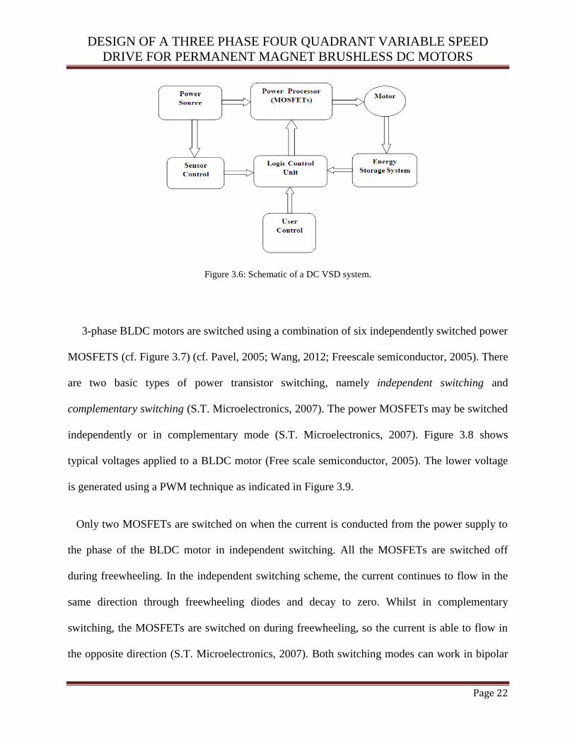
A generic E-bike controller schematic is given in Figure 3.6. The power source represents the
supply voltage from the battery which energizes the power MOSFETs to control the motor
phases. The sensors and the logic control unit controls the hall sensors for commutation.
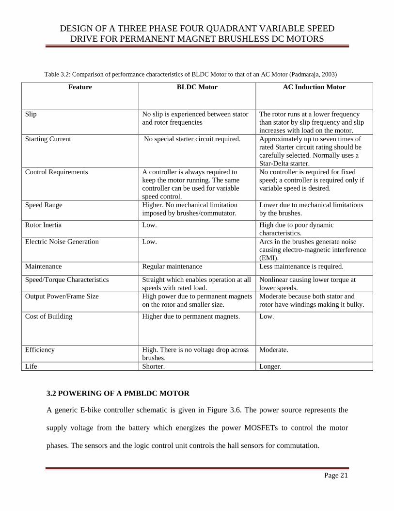
Table 3.2: Comparison of performance characteristics of BLDC Motor to that of an AC Motor (Padmaraja, 2003)
Feature BLDC Motor AC Induction Motor
Slip No slip is experienced between stator
and rotor frequencies
The rotor runs at a lower frequency
than stator by slip frequency and slip
increases with load on the motor.
Starting Current No special starter circuit required. Approximately up to seven times of
rated Starter circuit rating should be
carefully selected. Normally uses a
Star-Delta starter.
Control Requirements A controller is always required to
keep the motor running. The same
controller can be used for variable
speed control.
No controller is required for fixed
speed; a controller is required only if
variable speed is desired.
Speed Range Higher. No mechanical limitation
imposed by brushes/commutator.
Lower due to mechanical limitations
by the brushes.
Rotor Inertia Low. High due to poor dynamic
characteristics.
Electric Noise Generation Low. Arcs in the brushes generate noise
causing electro-magnetic interference
(EMI).
Maintenance Regular maintenance Less maintenance is required.
Speed/Torque Characteristics Straight which enables operation at all
speeds with rated load.
Nonlinear causing lower torque at
lower speeds.
Output Power/Frame Size High power due to permanent magnets
on the rotor and smaller size.
Moderate because both stator and
rotor have windings making it bulky.
Cost of Building Higher due to permanent magnets. Low.
Efficiency High. There is no voltage drop across
brushes.
Moderate.
Life Shorter. Longer.
DESIGN OF A THREE PHASE FOUR QUADRANT VARIABLE SPEED
DRIVE FOR PERMANENT MAGNET BRUSHLESS DC MOTORS
Page 22
Figure 3.6: Schematic of a DC VSD system.
3-phase BLDC motors are switched using a combination of six independently switched power
MOSFETS (cf. Figure 3.7) (cf. Pavel, 2005; Wang, 2012; Freescale semiconductor, 2005). There
are two basic types of power transistor switching, namely independent switching and
complementary switching (S.T. Microelectronics, 2007). The power MOSFETs may be switched
independently or in complementary mode (S.T. Microelectronics, 2007). Figure 3.8 shows
typical voltages applied to a BLDC motor (Free scale semiconductor, 2005). The lower voltage
is generated using a PWM technique as indicated in Figure 3.9.
Only two MOSFETs are switched on when the current is conducted from the power supply to
the phase of the BLDC motor in independent switching. All the MOSFETs are switched off
during freewheeling. In the independent switching scheme, the current continues to flow in the
same direction through freewheeling diodes and decay to zero. Whilst in complementary
switching, the MOSFETs are switched on during freewheeling, so the current is able to flow in
the opposite direction (S.T. Microelectronics, 2007). Both switching modes can work in bipolar
DESIGN OF A THREE PHASE FOUR QUADRANT VARIABLE SPEED
DRIVE FOR PERMANENT MAGNET BRUSHLESS DC MOTORS
Page 23
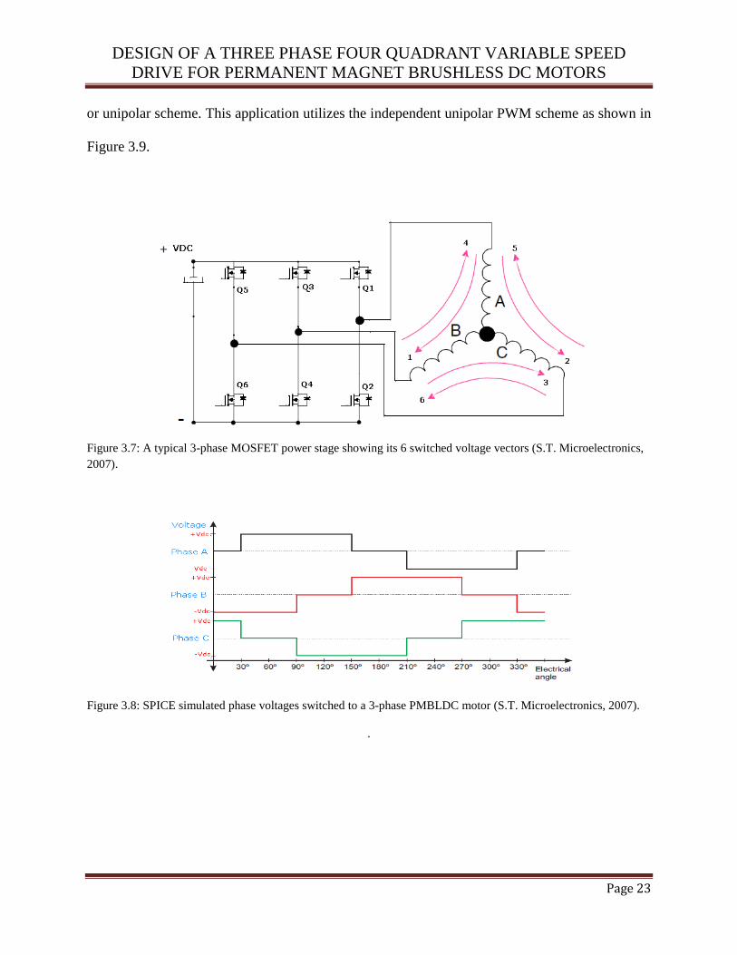
or unipolar scheme. This application utilizes the independent unipolar PWM scheme as shown in
Figure 3.9.
Figure 3.7: A typical 3-phase MOSFET power stage showing its 6 switched voltage vectors (S.T. Microelectronics,
2007).
Figure 3.8: SPICE simulated phase voltages switched to a 3-phase PMBLDC motor (S.T. Microelectronics, 2007).
.

DESIGN OF A THREE PHASE FOUR QUADRANT VARIABLE SPEED
DRIVE FOR PERMANENT MAGNET BRUSHLESS DC MOTORS
Page 24
Figure 3.9: SPICE simulated PWM switching signals for power MOSFET drivers . (S.T. Microelectronics, 2007).
3.2.1 Commutation
Commutation creates a rotation field. Proper operation of a BLDC motor requires the angle
between stator and rotor flux to remain close to 90° (Freescale Semiconductor, 2005). Six-step
control yields a total of six possible stator flux vectors. The stator flux vector must be changed at
a certain rotor position. The rotor position is usually detected by Hall Sensors. The Hall Sensors
directly detect the commutation moment. The application presented uses the hall sensors to sense
rotor position. The electrical revolution can be divided into six sectors. Each sector corresponds
to a certain stator flux vector as illustrated in Figure 3.10. The actual rotor position in Figure 3.11
corresponds to the sector ABC [binary pulse 110]. Phase A is connected to the positive DC bus
voltage by the MOSFET Q1, Phase C is connected to the ground by MOSFET Q6 and Phase B is
floating. The six-step control technique varies from an angle of 60° to 120° between the rotor
flux and the stator flux. The commutation is repeated every 600. The commutation process is
critical for its accuracy because any deviation can cause torque ripples and therefore, speed
variation. Each commutation sequence has one of the windings energized to positive power, the
second winding is negative and the third winding is non-energized. Torque is produced due to

DESIGN OF A THREE PHASE FOUR QUADRANT VARIABLE SPEED
DRIVE FOR PERMANENT MAGNET BRUSHLESS DC MOTORS
Page 25
the interaction between the magnetic field generated by the stator coils and the permanent
magnets. Ideally, the peak torque occurs when these two fields are at 90° to each other and falls
off as the fields move together (Lee and Eshsani, 2001). To keep the motor spinning, the
magnetic field produced by the windings should shift position with the movement of the rotor to
catch up with the stator field.
Figure 3.10: Stator flux vectors under 6-Step control Figure 3.11: Rotor position at a binary (Freescale Semiconductor, 2005). pulse 110 (Freescale Semiconductor, 2005).
The PMBLDC motor uses two pair conduction controls for the phase shift. Table 3.3, Table
3.4, Figure 3.12 and Figure 3.13 show the sequence in which these power switches should be
switched based on the Hall sensor inputs labeled A, B and C. The switching sequence in Table
3.3 corresponds with the clockwise rotation of the motor in Figure 3.12. And Table 3.4
corresponds with the counter clockwise motor rotation in Figure 3.13. When deriving a
controller for a particular motor, the sequence defined by the motor manufacturer should be
followed. To vary the speed, these signals should be Pulse Width Modulated (PWM) at a much
higher frequency than the motor frequency. When the duty cycle of PWM is varied within the
DESIGN OF A THREE PHASE FOUR QUADRANT VARIABLE SPEED
DRIVE FOR PERMANENT MAGNET BRUSHLESS DC MOTORS
Page 26
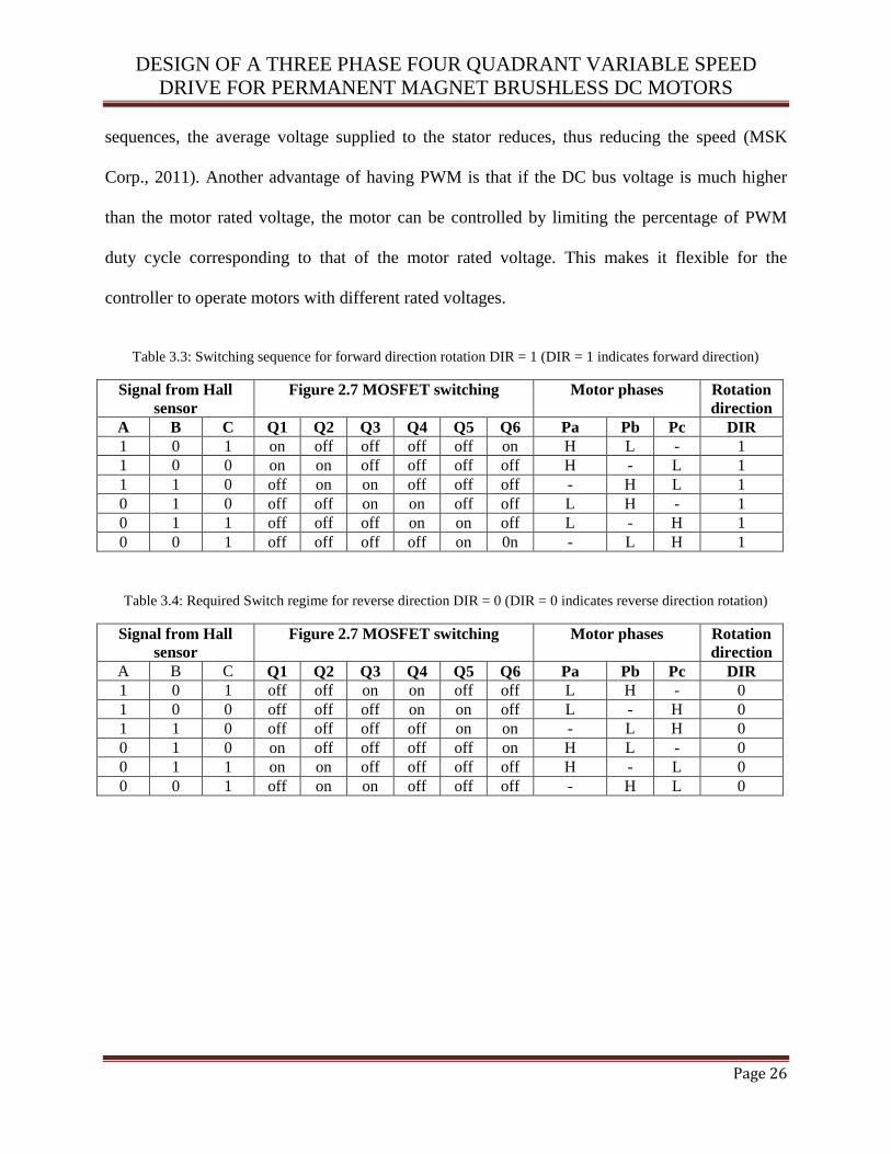
sequences, the average voltage supplied to the stator reduces, thus reducing the speed (MSK
Corp., 2011). Another advantage of having PWM is that if the DC bus voltage is much higher
than the motor rated voltage, the motor can be controlled by limiting the percentage of PWM
duty cycle corresponding to that of the motor rated voltage. This makes it flexible for the
controller to operate motors with different rated voltages.
Table 3.3: Switching sequence for forward direction rotation DIR = 1 (DIR = 1 indicates forward direction)
Signal from Hall
sensor
Figure 2.7 MOSFET switching Motor phases Rotation
direction
A B C Q1 Q2 Q3 Q4 Q5 Q6 Pa Pb Pc DIR
1 0 1 on off off off off on H L - 1
1 0 0 on on off off off off H - L 1
1 1 0 off on on off off off - H L 1
0 1 0 off off on on off off L H - 1
0 1 1 off off off on on off L - H 1
0 0 1 off off off off on 0n - L H 1
Table 3.4: Required Switch regime for reverse direction DIR = 0 (DIR = 0 indicates reverse direction rotation)
Signal from Hall
sensor
Figure 2.7 MOSFET switching Motor phases Rotation
direction
A B C Q1 Q2 Q3 Q4 Q5 Q6 Pa Pb Pc DIR
1 0 1 off off on on off off L H - 0
1 0 0 off off off on on off L - H 0
1 1 0 off off off off on on - L H 0
0 1 0 on off off off off on H L - 0
0 1 1 on on off off off off H - L 0
0 0 1 off on on off off off - H L 0

DESIGN OF A THREE PHASE FOUR QUADRANT VARIABLE SPEED
DRIVE FOR PERMANENT MAGNET BRUSHLESS DC MOTORS
Page 27
Figure 3.12: Forward direction binary sequence based on Figure 3.13: Reverse direction binary sequence based Table3..3 on Table3.4.
Figure 3.14 shows an example of Hall sensor signals with respect to back EMF and the phase
current. This is an example of Hall sensor signals having a 1200 phase shift with respect to each
other. One of the Hall sensors changes state at every 600 of rotation. Therefore it takes six steps
to complete one electrical cycle. The number of electrical cycles to be repeated to complete a
mechanical rotation is determined by the rotor pole pairs. One cycle is completed for each rotor
pole pair. Therefore the number of rotations equals the rotor pole pairs.
1 0 0
1 0 1
1 1 0 0 1 0
0 1 1
0 0 1 a
c
b
c
a
b
DIR
=1
1 0 0
1 0 1
1 1 0 0 1 0
0 1 1
0 0 1 a
c
b c
a
b
DIR
=0

DESIGN OF A THREE PHASE FOUR QUADRANT VARIABLE SPEED
DRIVE FOR PERMANENT MAGNET BRUSHLESS DC MOTORS
Page 28
Figure 3.14: SPICE simulation of phase voltages with Hall sensors at 120°.
DESIGN OF A THREE PHASE FOUR QUADRANT VARIABLE SPEED
DRIVE FOR PERMANENT MAGNET BRUSHLESS DC MOTORS
Page 29
3.2.2 Back EMF
When a BLDC motor rotates, each winding generates a back EMF. The polarity of this back
EMF is in opposite direction of the energized voltage. When the motor is at steady state, this
voltage closely matches the supply voltage applied to the motor (Pavel, 2005). When the motor
is spinning and the load is increased its speed will drop therefore causing the back EMF to also
drop and hence the current drawn by the motor will increase. By Ohm’s Law, the current drawn
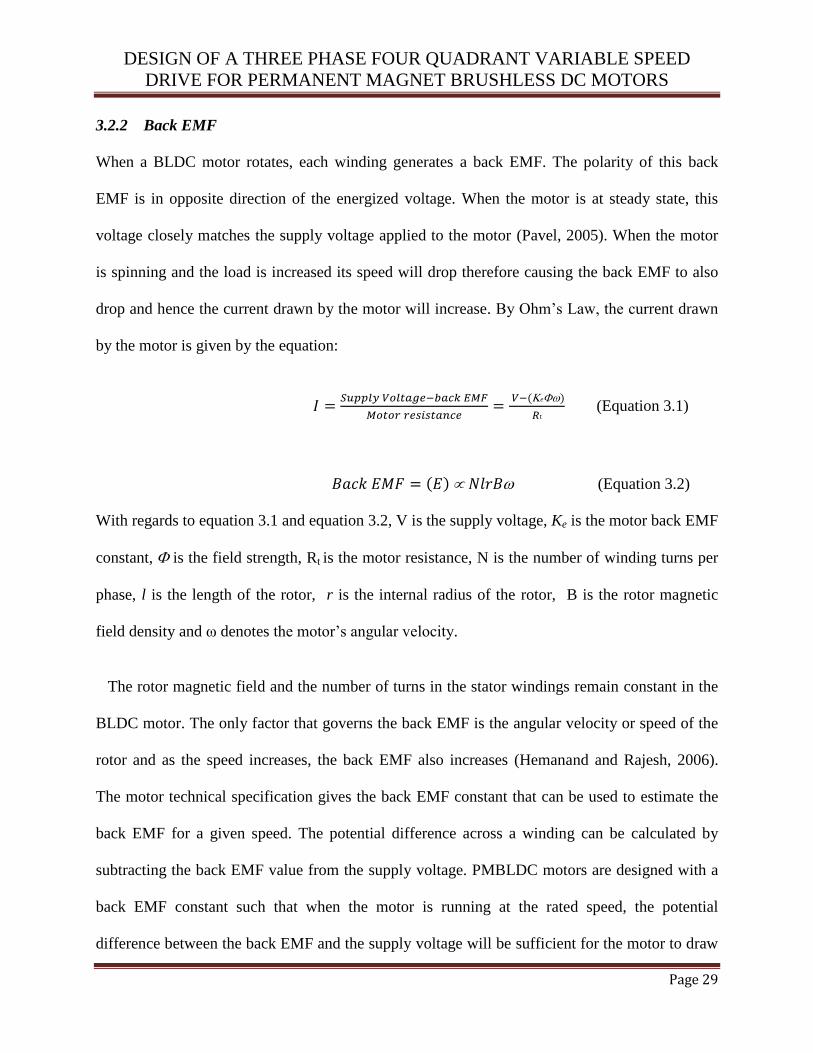
by the motor is given by the equation:
(Equation 3.1)
(Equation 3.2)
With regards to equation 3.1 and equation 3.2, V is the supply voltage, Ke is the motor back EMF
constant, is the field strength, Rt is the motor resistance, N is the number of winding turns per
phase, l is the length of the rotor, r is the internal radius of the rotor, B is the rotor magnetic
field density and ω denotes the motor’s angular velocity.
The rotor magnetic field and the number of turns in the stator windings remain constant in the
BLDC motor. The only factor that governs the back EMF is the angular velocity or speed of the
rotor and as the speed increases, the back EMF also increases (Hemanand and Rajesh, 2006).
The motor technical specification gives the back EMF constant that can be used to estimate the
back EMF for a given speed. The potential difference across a winding can be calculated by
subtracting the back EMF value from the supply voltage. PMBLDC motors are designed with a
back EMF constant such that when the motor is running at the rated speed, the potential
difference between the back EMF and the supply voltage will be sufficient for the motor to draw

DESIGN OF A THREE PHASE FOUR QUADRANT VARIABLE SPEED
DRIVE FOR PERMANENT MAGNET BRUSHLESS DC MOTORS
Page 30
the rated current and deliver the rated torque (Tashakori and Ektsesabi, 2012). If the motor is
driven beyond the rated speed, back EMF may increase substantially, thus decreasing the
potential difference across the winding, reducing the current drawn which results in dropping
torque curve.
3.2.3 Torque
The torque produced by a PMBLDC motor is directly proportional to the motor current.
Therefore to effectively control the torque, a sensor is used to sense the motor current. The motor
current is amplified using operational amplifiers. The peak or maximum torque required for the
application can be calculated by summing the load torque, torque due to inertia and the torque
required to overcome the friction (Padmaraja, 2003). There are other factors such as the
resistance in the air gap which contribute to the overall peak torque requirements (Tshikawa and
Slemon, 2012). The torque produced by a permanent magnet motor is given by the equation
(Salam, 2003):
(Equation 3.3)
With regards to equation 3.3, T is the torque, is the EMF constant for the motor, is the
armature current and represents the field strength.
3.2.4 Speed control
The speed is directly proportional to the supply voltage in the BLDC motor. The commutation
ensures the proper rotation of the BLDC motor, while the motor speed depends only on the

DESIGN OF A THREE PHASE FOUR QUADRANT VARIABLE SPEED
DRIVE FOR PERMANENT MAGNET BRUSHLESS DC MOTORS
Page 31
amplitude of the supply voltage. This amplitude can be controlled by the PWM technique. The
technique to BLDC commutation is to sense the rotor position, then energize the phases that will
produce maximum torque. The rotor travels 600 per commutation step. The appropriate stator
current path is activated when the rotor is 1200 from alignment with the corresponding stator
magnetic field (Chengang and Yaochun, 2010). The stator current is deactivated when the rotor
is 600 from alignment at which time the next phase is activated and the process repeats.
Commutating the electrical connections through the six possible combinations will pull the rotor
through one electrical revolution. The speed can be expressed by the given equation:
(Equation 3.4)
With regards to equation 3.4, is the motor speed, is the motor voltage constant, is the
armature voltage and fI denotes the field current.
3.2.5 Power efficiency
The power drawn by a motor from the supply is given by:
(Equation 3.5)
The mechanical power produced by the motor is given by:
TPout (Equation 3.6)
fv
a
IK
V
DESIGN OF A THREE PHASE FOUR QUADRANT VARIABLE SPEED
DRIVE FOR PERMANENT MAGNET BRUSHLESS DC MOTORS
Page 32
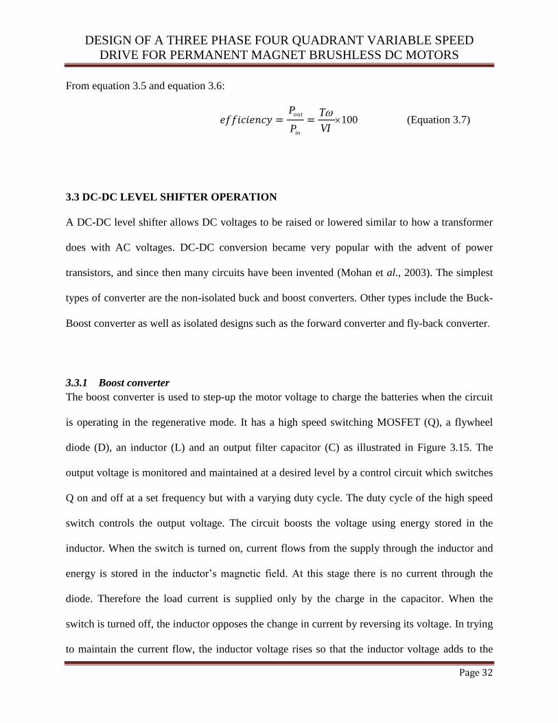
From equation 3.5 and equation 3.6:
outP
inP
T
VI100 (Equation 3.7)
3.3 DC-DC LEVEL SHIFTER OPERATION
A DC-DC level shifter allows DC voltages to be raised or lowered similar to how a transformer
does with AC voltages. DC-DC conversion became very popular with the advent of power
transistors, and since then many circuits have been invented (Mohan et al., 2003). The simplest
types of converter are the non-isolated buck and boost converters. Other types include the Buck-
Boost converter as well as isolated designs such as the forward converter and fly-back converter.
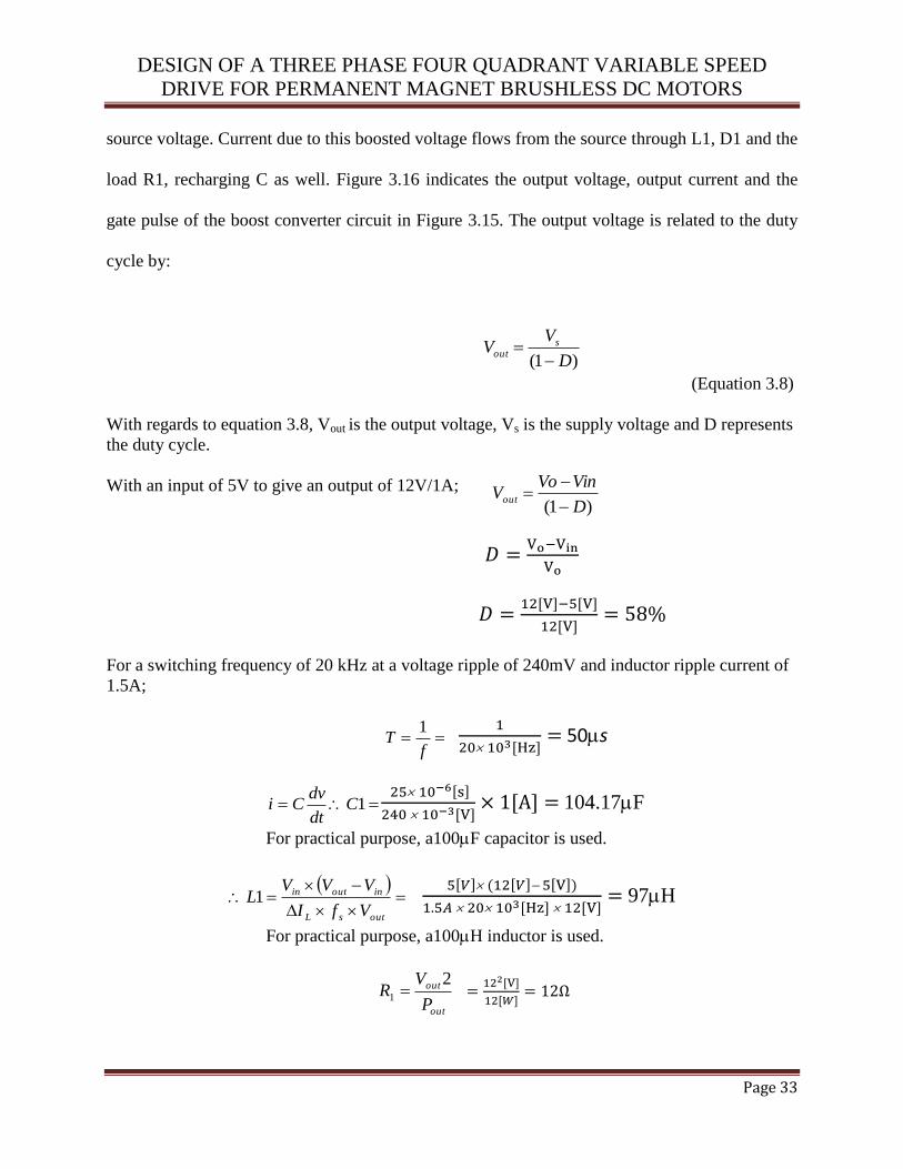
3.3.1 Boost converter
The boost converter is used to step-up the motor voltage to charge the batteries when the circuit
is operating in the regenerative mode. It has a high speed switching MOSFET (Q), a flywheel
diode (D), an inductor (L) and an output filter capacitor (C) as illustrated in Figure 3.15. The
output voltage is monitored and maintained at a desired level by a control circuit which switches
Q on and off at a set frequency but with a varying duty cycle. The duty cycle of the high speed
switch controls the output voltage. The circuit boosts the voltage using energy stored in the
inductor. When the switch is turned on, current flows from the supply through the inductor and
energy is stored in the inductor’s magnetic field. At this stage there is no current through the
diode. Therefore the load current is supplied only by the charge in the capacitor. When the
switch is turned off, the inductor opposes the change in current by reversing its voltage. In trying
to maintain the current flow, the inductor voltage rises so that the inductor voltage adds to the
DESIGN OF A THREE PHASE FOUR QUADRANT VARIABLE SPEED
DRIVE FOR PERMANENT MAGNET BRUSHLESS DC MOTORS
Page 33
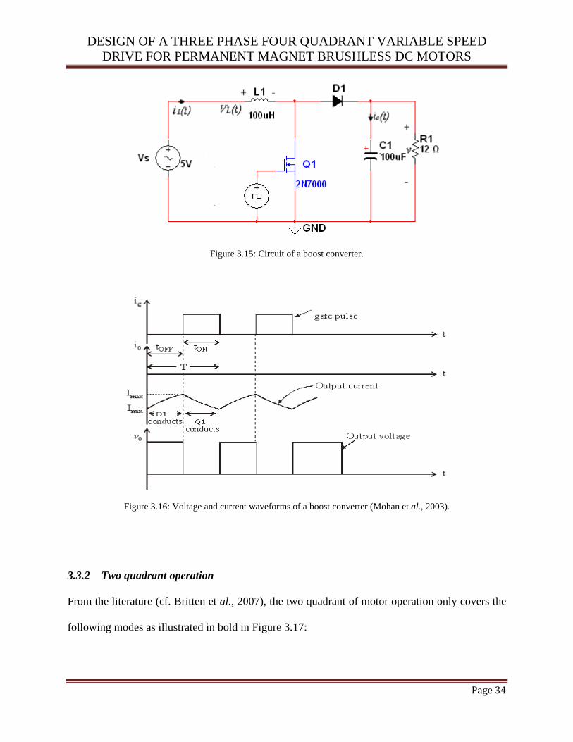
source voltage. Current due to this boosted voltage flows from the source through L1, D1 and the
load R1, recharging C as well. Figure 3.16 indicates the output voltage, output current and the
gate pulse of the boost converter circuit in Figure 3.15. The output voltage is related to the duty
cycle by:
(Equation 3.8)
With regards to equation 3.8, Vout is the output voltage, Vs is the supply voltage and D represents
the duty cycle.
With an input of 5V to give an output of 12V/1A;
For a switching frequency of 20 kHz at a voltage ripple of 240mV and inductor ripple current of
1.5A;
f
T1
50s
1Cdt
dvCi
104.17F
For practical purpose, a100F capacitor is used.
outsL
inoutin
VfI
VVVL1
97H
For practical purpose, a100H inductor is used.
out
out
P
VR
21
)1( D
VV s
out
)1( D
VinVoVout
DESIGN OF A THREE PHASE FOUR QUADRANT VARIABLE SPEED
DRIVE FOR PERMANENT MAGNET BRUSHLESS DC MOTORS
Page 34
Figure 3.15: Circuit of a boost converter.
Figure 3.16: Voltage and current waveforms of a boost converter (Mohan et al., 2003).
3.3.2 Two quadrant operation
From the literature (cf. Britten et al., 2007), the two quadrant of motor operation only covers the
following modes as illustrated in bold in Figure 3.17:

DESIGN OF A THREE PHASE FOUR QUADRANT VARIABLE SPEED
DRIVE FOR PERMANENT MAGNET BRUSHLESS DC MOTORS
Page 35
Operating mode 1: Forward motoring that generates a positive voltage and a positive current.
Operating mode 2: Forward regeneration that generates a positive voltage and a negative current.
Figure 3.17: Two quadrants of motor operation (the quadrants where motoring and generation in forward direction
occurs are indicated in bold).
The VSD puts the BLDC motor into generating mode when the throttle detects a negative
current. The motor has to be moving to convert mechanical energy to electrical energy. Active
braking zone in the generating quadrant is unreachable for the VSD designed for two quadrants
in the same mechanical direction (Britten et al., 2007). The controller can only short the motor
terminals, causing a maximum negative current that is proportional to the speed. This is the case
for a BLDC motor with a two quadrant drive as illustrated in bold in Figure 3.17 (Salam, 2003).
The measurements of torque were not very accurate and prevented meaningful analysis of
efficiency (Britten et al., 2007).
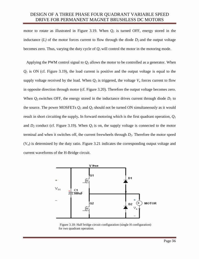
The two quadrant operation uses the half bridge configuration as shown in Figure 3.18. The
PWM technique is used to control the switches in the half bridge circuit to vary the power
delivered to the motor. Q1 and D2 form a step down converter that can reduce the voltage to the
motor. Current flows from the battery to the motor when Q1 switches on, therefore causing the
Motoring in
Forward
Direction
Generating in
Forward
Direction
Motoring in
Reverse
Direction
Generating in
Reverse
Direction
Tm
m
DESIGN OF A THREE PHASE FOUR QUADRANT VARIABLE SPEED
DRIVE FOR PERMANENT MAGNET BRUSHLESS DC MOTORS
Page 36
motor to rotate as illustrated in Figure 3.19. When Q1 is turned OFF, energy stored in the
inductance (L) of the motor forces current to flow through the diode D2 and the output voltage
becomes zero. Thus, varying the duty cycle of Q1 will control the motor in the motoring mode.
Applying the PWM control signal to Q2 allows the motor to be controlled as a generator. When
Q1 is ON (cf. Figure 3.19), the load current is positive and the output voltage is equal to the
supply voltage received by the load. When Q2 is triggered, the voltage Va forces current to flow
in opposite direction through motor (cf. Figure 3.20). Therefore the output voltage becomes zero.
When Q2 switches OFF, the energy stored in the inductance drives current through diode D1 to
the source. The power MOSFETs Q1 and Q2 should not be turned ON simultaneously as it would
result in short circuiting the supply. In forward motoring which is the first quadrant operation, Q1
and D2 conduct (cf. Figure 3.19). When Q1 is on, the supply voltage is connected to the motor
terminal and when it switches off, the current freewheels through D2. Therefore the motor speed
(Va) is determined by the duty ratio. Figure 3.21 indicates the corresponding output voltage and
current waveforms of the H-Bridge circuit.
Figure 3.18: Half bridge circuit configuration (single H configuration)
for two quadrant operation.

DESIGN OF A THREE PHASE FOUR QUADRANT VARIABLE SPEED
DRIVE FOR PERMANENT MAGNET BRUSHLESS DC MOTORS
Page 37
Figure 3.19: Forward motoring when Q1 is conducting: va = Vdc
D2 conducts va = 0.
Figure 3.20: Regeneration when D1 is conducting: va = Vdc
Q2 conducts va = 0.

DESIGN OF A THREE PHASE FOUR QUADRANT VARIABLE SPEED
DRIVE FOR PERMANENT MAGNET BRUSHLESS DC MOTORS
Page 38
Figure 3.21: Measured output voltage and current waveforms of the H-bridge circuit (Mohan et al., 2003).
3.4 SUMMARY AND CONCLUSIONS
This chapter has discussed the basic BLDC motor theory, system design concepts and hardware
implementation. From the literature and based on personal experience, BLDC motors have
advantages over brushed DC motors and induction motors. They have better speed versus torque
characteristics, high dynamic response, high efficiency, long operating life, noiseless operation,
higher speed ranges and low maintenance. Also, torque delivered to the motor size is higher,
making it useful in applications where space and weight are critical factors. With these
advantages, BLDC motors find wide spread applications in automotive, appliance, aerospace,
instrumentation and automation industries. The next chapter will discuss a variant of 4 quadrant
operation which was used for the drive system proposed in this study.
DESIGN OF A THREE PHASE FOUR QUADRANT VARIABLE SPEED
DRIVE FOR PERMANENT MAGNET BRUSHLESS DC MOTORS
Page 39
This page is intentionally blank

DESIGN OF A THREE PHASE FOUR QUADRANT VARIABLE SPEED
DRIVE FOR PERMANENT MAGNET BRUSHLESS DC MOTORS
Page 40
CHAPTER 4
HARDWARE DESIGN FOR THE PROPOSED
4-QUADRANT VARIABLE SPEED DRIVE
4.1 INTRODUCTION
This chapter discusses the author’s original design for the four quadrant speed control system. It
discusses the various parts, design and their respective functions in the control system. The
PMBLDC motor is a perfect choice with simple drive requirements for this application. Thus
FDP3632 MOSFET’s, LM5101 drive, GWM100-01X1 three phase full bridge, ATmega328 or
CPLD and SG3524 were chosen as the main components. The design accommodates the
following practical specifications: 36V-DC battery, 500W trapezoidal back EMF BLDC motor, 3
Hall effect rotor position sensors, arranged in a 3600 configuration and a control input or throttle
signal that is derived from an angular position sensor that produces a 1VDC to 5VDC signal.
4.2 FOUR QUADRANT OPERATION
The 4- quadrant drive control system proposed in this study (cf. Figure 4.1) utilises the following
4 operating modes:
Operating mode 1: Forward motoring that generates a positive voltage and a positive
current.
Operating mode 2: Forward regeneration to generate a positive voltage and a negative
current.
Operating mode 3: Reverse motoring that generates negative voltage and negative
current.

DESIGN OF A THREE PHASE FOUR QUADRANT VARIABLE SPEED
DRIVE FOR PERMANENT MAGNET BRUSHLESS DC MOTORS
Page 41
Operating mode 4: Reverse regeneration to generate a negative voltage and a positive
current.
Figure 4.1: The four quadrants of motor operation.
The four quadrant drive uses the simplest logic function while regenerating electrical energy
from the PMBL motor. As an added economic advantage, the method for regenerating electrical
energy can reduce brake pad wear and thus brake pad replacement frequency. With the ability to
return energy to the energy storage devices (battery-capacitor technology), the proposed VSD
can also be used as an emergency low power generator. Regeneration takes place in the energy
storage system and user control represents the throttle. The benefits of using 4 quadrant current-
mode motor control are (Salam, 2003):
The ability to smoothly control the current delivered to the motor, thus controlling its
torque and speed.
Motoring in
Forward
Direction
Generating in
Forward
Direction
Motoring in
Reverse
Direction
Generating in
Reverse
Direction
MODE 2 MODE 3
MODE 4
Tm
m
MODE 1
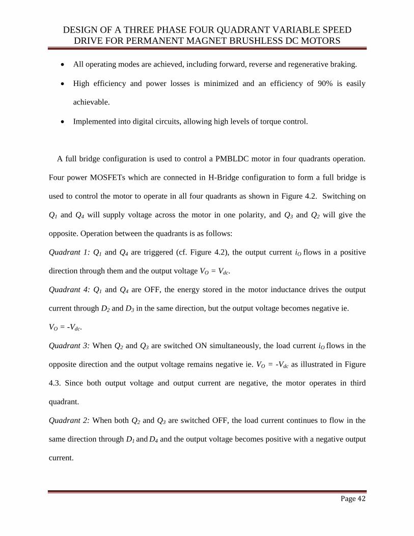
DESIGN OF A THREE PHASE FOUR QUADRANT VARIABLE SPEED
DRIVE FOR PERMANENT MAGNET BRUSHLESS DC MOTORS
Page 42
All operating modes are achieved, including forward, reverse and regenerative braking.
High efficiency and power losses is minimized and an efficiency of 90% is easily
achievable.
Implemented into digital circuits, allowing high levels of torque control.
A full bridge configuration is used to control a PMBLDC motor in four quadrants operation.
Four power MOSFETs which are connected in H-Bridge configuration to form a full bridge is
used to control the motor to operate in all four quadrants as shown in Figure 4.2. Switching on
Q1 and Q4 will supply voltage across the motor in one polarity, and Q3 and Q2 will give the
opposite. Operation between the quadrants is as follows:
Quadrant 1: Q1 and Q4 are triggered (cf. Figure 4.2), the output current iO flows in a positive
direction through them and the output voltage VO = Vdc.
Quadrant 4: Q1 and Q4 are OFF, the energy stored in the motor inductance drives the output
current through D2 and D3 in the same direction, but the output voltage becomes negative ie.
VO = -Vdc.
Quadrant 3: When Q2 and Q3 are switched ON simultaneously, the load current iO flows in the
opposite direction and the output voltage remains negative ie. VO = -Vdc as illustrated in Figure
4.3. Since both output voltage and output current are negative, the motor operates in third
quadrant.
Quadrant 2: When both Q2 and Q3 are switched OFF, the load current continues to flow in the
same direction through D1 and D4 and the output voltage becomes positive with a negative output
current.
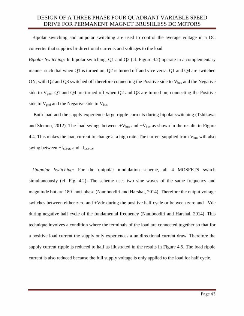
DESIGN OF A THREE PHASE FOUR QUADRANT VARIABLE SPEED
DRIVE FOR PERMANENT MAGNET BRUSHLESS DC MOTORS
Page 43
Bipolar switching and unipolar switching are used to control the average voltage in a DC
converter that supplies bi-directional currents and voltages to the load.
Bipolar Switching: In bipolar switching, Q1 and Q2 (cf. Figure 4.2) operate in a complementary
manner such that when Q1 is turned on, Q2 is turned off and vice versa. Q1 and Q4 are switched
ON, with Q2 and Q3 switched off therefore connecting the Positive side to Vbus and the Negative
side to Vgnd. Q1 and Q4 are turned off when Q2 and Q3 are turned on; connecting the Positive
side to Vgnd and the Negative side to Vbus.
Both load and the supply experience large ripple currents during bipolar switching (Tshikawa
and Slemon, 2012). The load swings between +Vbus and −Vbus as shown in the results in Figure
4.4. This makes the load current to change at a high rate. The current supplied from Vbus will also
swing between +ILOAD and –ILOAD.
Unipolar Switching: For the unipolar modulation scheme, all 4 MOSFETS switch
simultaneously (cf. Fig. 4.2). The scheme uses two sine waves of the same frequency and
magnitude but are 1800 anti-phase (Namboodiri and Harshal, 2014). Therefore the output voltage
switches between either zero and +Vdc during the positive half cycle or between zero and –Vdc
during negative half cycle of the fundamental frequency (Namboodiri and Harshal, 2014). This
technique involves a condition where the terminals of the load are connected together so that for
a positive load current the supply only experiences a unidirectional current draw. Therefore the
supply current ripple is reduced to half as illustrated in the results in Figure 4.5. The load ripple
current is also reduced because the full supply voltage is only applied to the load for half cycle.
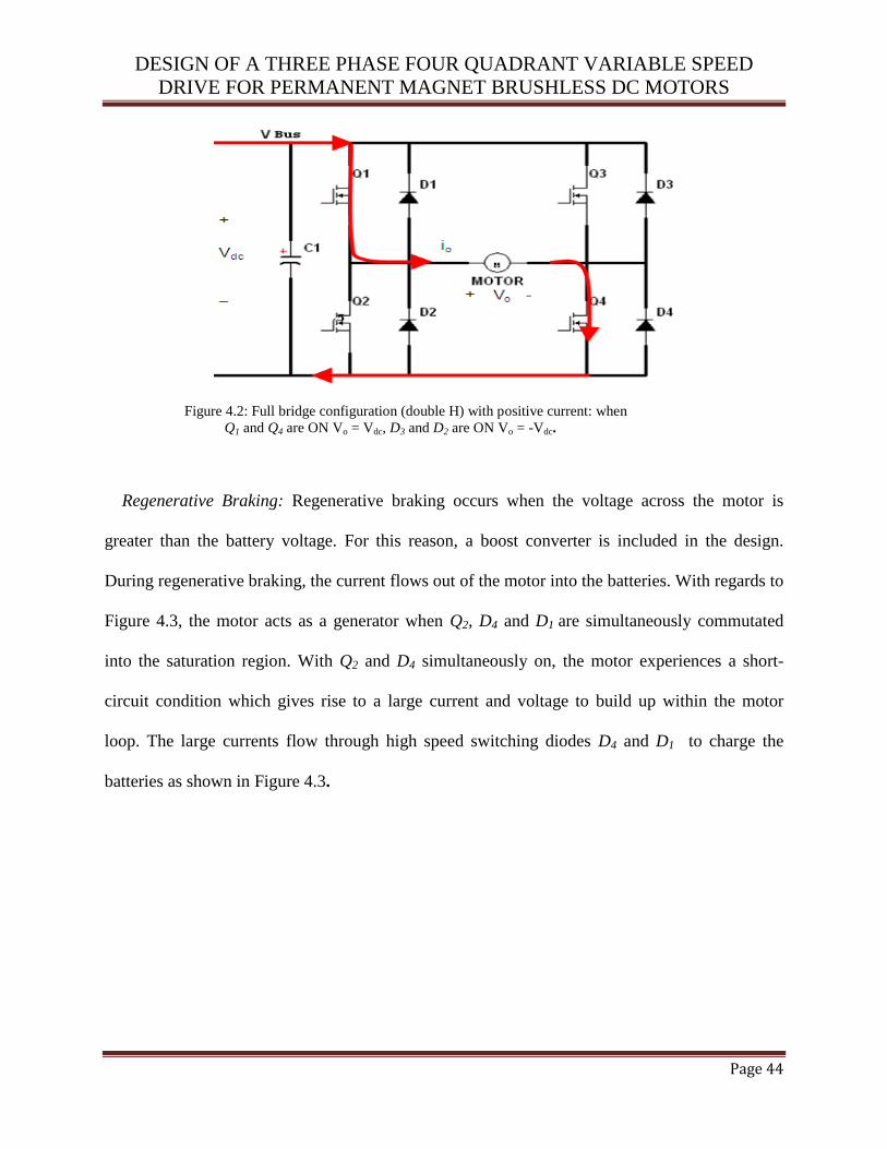
DESIGN OF A THREE PHASE FOUR QUADRANT VARIABLE SPEED
DRIVE FOR PERMANENT MAGNET BRUSHLESS DC MOTORS
Page 44
Figure 4.2: Full bridge configuration (double H) with positive current: when
Q1 and Q4 are ON Vo = Vdc, D3 and D2 are ON Vo = -Vdc.
Regenerative Braking: Regenerative braking occurs when the voltage across the motor is
greater than the battery voltage. For this reason, a boost converter is included in the design.
During regenerative braking, the current flows out of the motor into the batteries. With regards to
Figure 4.3, the motor acts as a generator when Q2, D4 and D1 are simultaneously commutated
into the saturation region. With Q2 and D4 simultaneously on, the motor experiences a short-
circuit condition which gives rise to a large current and voltage to build up within the motor
loop. The large currents flow through high speed switching diodes D4 and D1 to charge the
batteries as shown in Figure 4.3.

DESIGN OF A THREE PHASE FOUR QUADRANT VARIABLE SPEED
DRIVE FOR PERMANENT MAGNET BRUSHLESS DC MOTORS
Page 45
Figure 4.3: Full bridge configuration with negative current: when
D1 and D4 are ON Vo = Vdc, Q3 and Q2 are ON Vo = -Vdc.
Figure 4.4: SPICE simulation of 4-quadrant bipolar switching (output swings between VDC and -VDC).
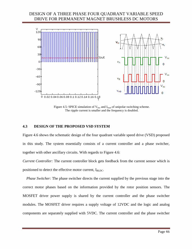
DESIGN OF A THREE PHASE FOUR QUADRANT VARIABLE SPEED
DRIVE FOR PERMANENT MAGNET BRUSHLESS DC MOTORS
Page 46
Figure 4.5: SPICE simulation of Vbus and Iload of unipolar switching scheme.
The ripple current is smaller and the frequency is doubled.
4.3 DESIGN OF THE PROPOSED VSD SYSTEM
Figure 4.6 shows the schematic design of the four quadrant variable speed drive (VSD) proposed
in this study. The system essentially consists of a current controller and a phase switcher,
together with other ancillary circuits. With regards to Figure 4.6:
Current Controller: The current controller block gets feedback from the current sensor which is
positioned to detect the effective motor current, IBLDC.
Phase Switcher: The phase switcher directs the current supplied by the previous stage into the
correct motor phases based on the information provided by the rotor position sensors. The
MOSFET driver power supply is shared by the current controller and the phase switcher
modules. The MOSFET driver requires a supply voltage of 12VDC and the logic and analog
components are separately supplied with 5VDC. The current controller and the phase switcher

DESIGN OF A THREE PHASE FOUR QUADRANT VARIABLE SPEED
DRIVE FOR PERMANENT MAGNET BRUSHLESS DC MOTORS
Page 47
are isolated from each other. A detailed description of the proposed four quadrant speed control
system follows.
Figure 4.6: Four quadrant control system.
4.3.1 Three phase switcher design
The GWM100-01X1 is a three-phase full bridge circuit with an isolated high voltage and current
package. The bridge system has six temperature regulated trench MOSFETs in direct copper
bonding (DCB) for driving the three phases of the BLDC motor as shown in Figure 4.8. It has a
voltage and current rating of 100V and 90A, respectively and a switching frequency of 20 kHz
(IXYS, 2009), and is suitable for a wide range of applications in automobiles and industrial
vehicles where high power and torque are necessary. The phase switcher module of the VSD is

DESIGN OF A THREE PHASE FOUR QUADRANT VARIABLE SPEED
DRIVE FOR PERMANENT MAGNET BRUSHLESS DC MOTORS
Page 48
required to accept the inputs from the Hall-effect position sensors and use that information to
effectively transform the BLDC motor into its DC motor equivalent. Figure 4.7 illustrates the
schematic diagram of a complete phase switcher design. For this project, the DC bus voltage is
maintained at 36V, and is the same as the voltage rating of the BLDC motor. The DC bus voltage
is monitored with a protection logic controller.
Figure 4.7: Phase switcher schematic.
Figure 4.8: GWM100-01X1 – full bridge phase switcher.
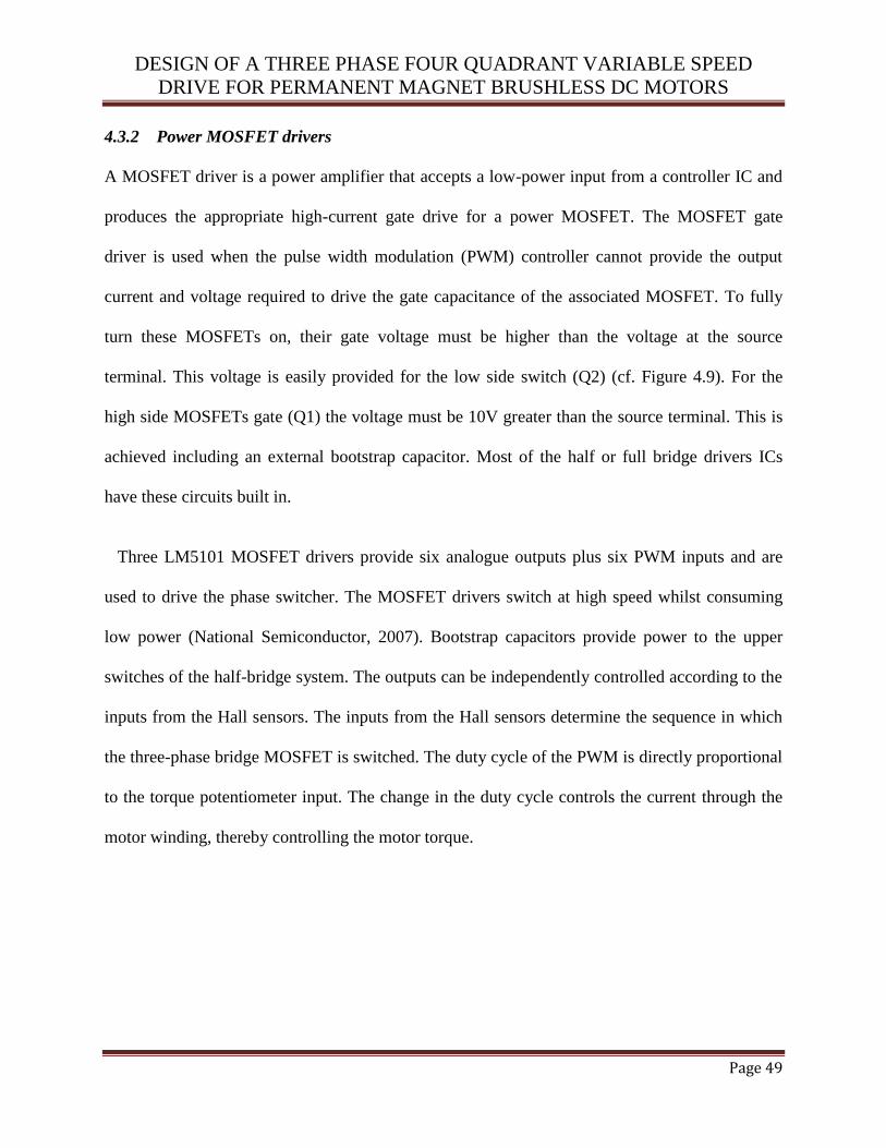
DESIGN OF A THREE PHASE FOUR QUADRANT VARIABLE SPEED
DRIVE FOR PERMANENT MAGNET BRUSHLESS DC MOTORS
Page 49
4.3.2 Power MOSFET drivers
A MOSFET driver is a power amplifier that accepts a low-power input from a controller IC and
produces the appropriate high-current gate drive for a power MOSFET. The MOSFET gate
driver is used when the pulse width modulation (PWM) controller cannot provide the output
current and voltage required to drive the gate capacitance of the associated MOSFET. To fully
turn these MOSFETs on, their gate voltage must be higher than the voltage at the source
terminal. This voltage is easily provided for the low side switch (Q2) (cf. Figure 4.9). For the
high side MOSFETs gate (Q1) the voltage must be 10V greater than the source terminal. This is
achieved including an external bootstrap capacitor. Most of the half or full bridge drivers ICs
have these circuits built in.
Three LM5101 MOSFET drivers provide six analogue outputs plus six PWM inputs and are
used to drive the phase switcher. The MOSFET drivers switch at high speed whilst consuming
low power (National Semiconductor, 2007). Bootstrap capacitors provide power to the upper
switches of the half-bridge system. The outputs can be independently controlled according to the
inputs from the Hall sensors. The inputs from the Hall sensors determine the sequence in which
the three-phase bridge MOSFET is switched. The duty cycle of the PWM is directly proportional
to the torque potentiometer input. The change in the duty cycle controls the current through the
motor winding, thereby controlling the motor torque.
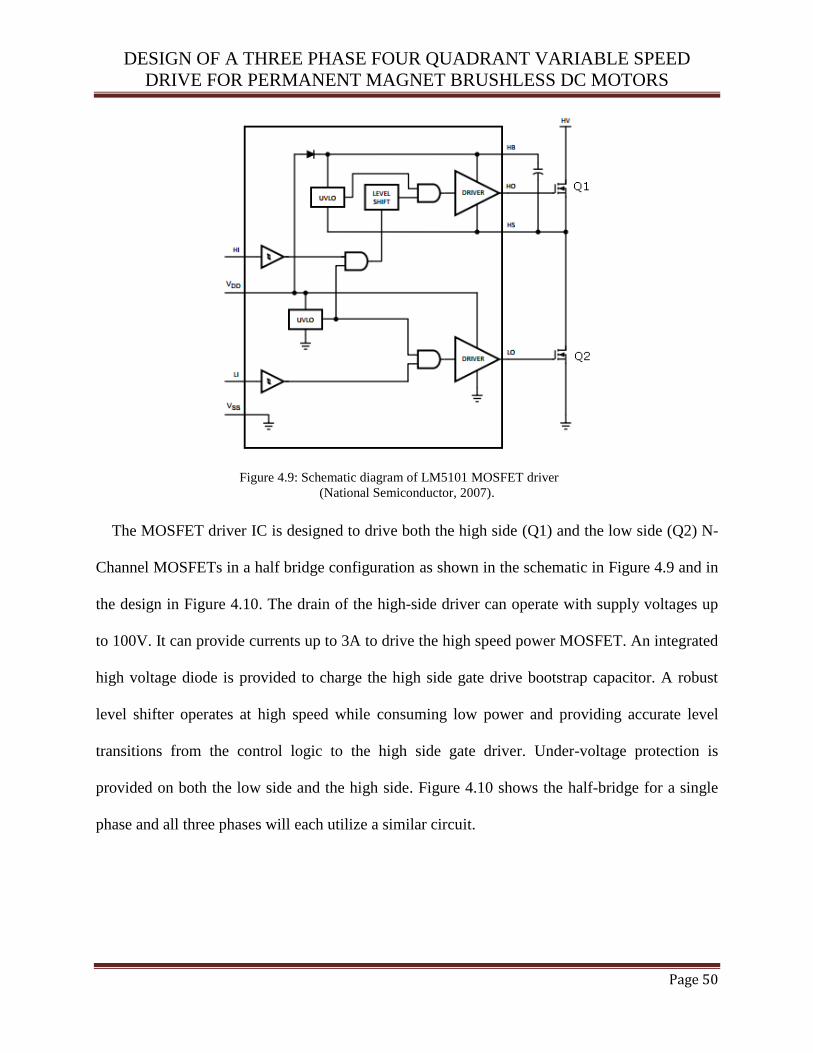
DESIGN OF A THREE PHASE FOUR QUADRANT VARIABLE SPEED
DRIVE FOR PERMANENT MAGNET BRUSHLESS DC MOTORS
Page 50
Figure 4.9: Schematic diagram of LM5101 MOSFET driver
(National Semiconductor, 2007).
The MOSFET driver IC is designed to drive both the high side (Q1) and the low side (Q2) N-
Channel MOSFETs in a half bridge configuration as shown in the schematic in Figure 4.9 and in
the design in Figure 4.10. The drain of the high-side driver can operate with supply voltages up
to 100V. It can provide currents up to 3A to drive the high speed power MOSFET. An integrated
high voltage diode is provided to charge the high side gate drive bootstrap capacitor. A robust
level shifter operates at high speed while consuming low power and providing accurate level
transitions from the control logic to the high side gate driver. Under-voltage protection is
provided on both the low side and the high side. Figure 4.10 shows the half-bridge for a single
phase and all three phases will each utilize a similar circuit.

DESIGN OF A THREE PHASE FOUR QUADRANT VARIABLE SPEED
DRIVE FOR PERMANENT MAGNET BRUSHLESS DC MOTORS
Page 51
Figure 4.10: Half-bridge LM5101 MOSFET driver circuit.
4.3.3 Protection logic control
To avoid both the high and low side MOSFETs switching on at the same time, a time delay logic
control is implemented to control the PWM signal to operate only one half of the bridge at any
one time. This prevents the occurrence of a short circuit condition which would destroy the
power MOSFETs. The circuit shown in Figure 4.11 is constructed using a LM347 op-amp
comparator. The comparator provides three input signals, the PWM signal and two signals for
the high side or low side MOSFETs. These devices are low-cost, high-speed and JFET-input
operational amplifiers. They require low supply current yet maintain a large gain-bandwidth
product and a fast slew rate. In addition, their matched high-voltage JFET inputs provide very
low input bias and offset current (Texas Instruments, 2005). This IC is used to create two
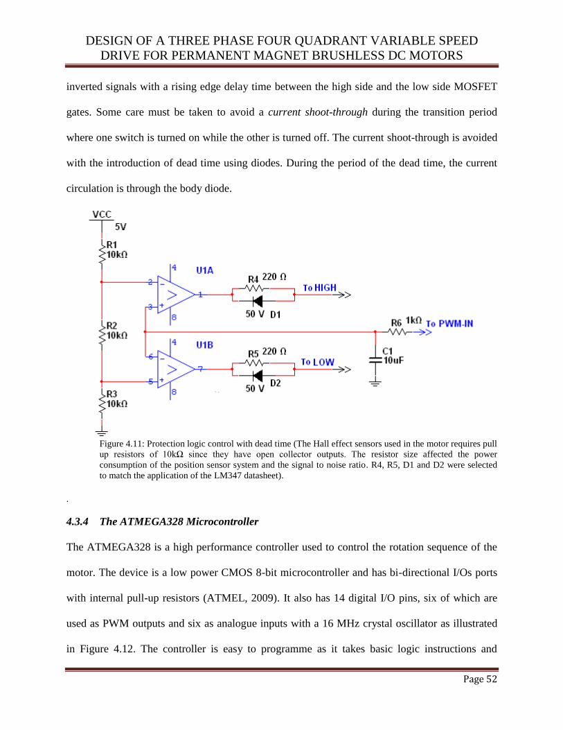
DESIGN OF A THREE PHASE FOUR QUADRANT VARIABLE SPEED
DRIVE FOR PERMANENT MAGNET BRUSHLESS DC MOTORS
Page 52
inverted signals with a rising edge delay time between the high side and the low side MOSFET
gates. Some care must be taken to avoid a current shoot-through during the transition period
where one switch is turned on while the other is turned off. The current shoot-through is avoided
with the introduction of dead time using diodes. During the period of the dead time, the current
circulation is through the body diode.
Figure 4.11: Protection logic control with dead time (The Hall effect sensors used in the motor requires pull
up resistors of 10kΩ since they have open collector outputs. The resistor size affected the power
consumption of the position sensor system and the signal to noise ratio. R4, R5, D1 and D2 were selected
to match the application of the LM347 datasheet).
.
4.3.4 The ATMEGA328 Microcontroller
The ATMEGA328 is a high performance controller used to control the rotation sequence of the
motor. The device is a low power CMOS 8-bit microcontroller and has bi-directional I/Os ports
with internal pull-up resistors (ATMEL, 2009). It also has 14 digital I/O pins, six of which are
used as PWM outputs and six as analogue inputs with a 16 MHz crystal oscillator as illustrated
in Figure 4.12. The controller is easy to programme as it takes basic logic instructions and

DESIGN OF A THREE PHASE FOUR QUADRANT VARIABLE SPEED
DRIVE FOR PERMANENT MAGNET BRUSHLESS DC MOTORS
Page 53
therefore, was programmed using PIC BasicPro compiler as shown in the coding in Appendix B.
The rationale used for the software design is given in the flowchart shown in Figure 4.13. The
logic circuit for forward and reverse control is given in Figure 4.14. The motor has three Hall
sensors embedded into the stator, spaced 1200 apart. Each Hall sensor provides either a high or
low signal based on the magnetic polarity closest to it. When the rotor passes near the Hall
sensors, only two MOSFETs switch on to indicate the phase shift. The microcontroller generates
a sequence control signal when the Hall sensors detect a new position. The rotor position is
determined by analyzing the outputs of all three Hall devices.
Figure 4.12: ATMEGA328 microcontroller for the logic control (ATMEL, 2009).
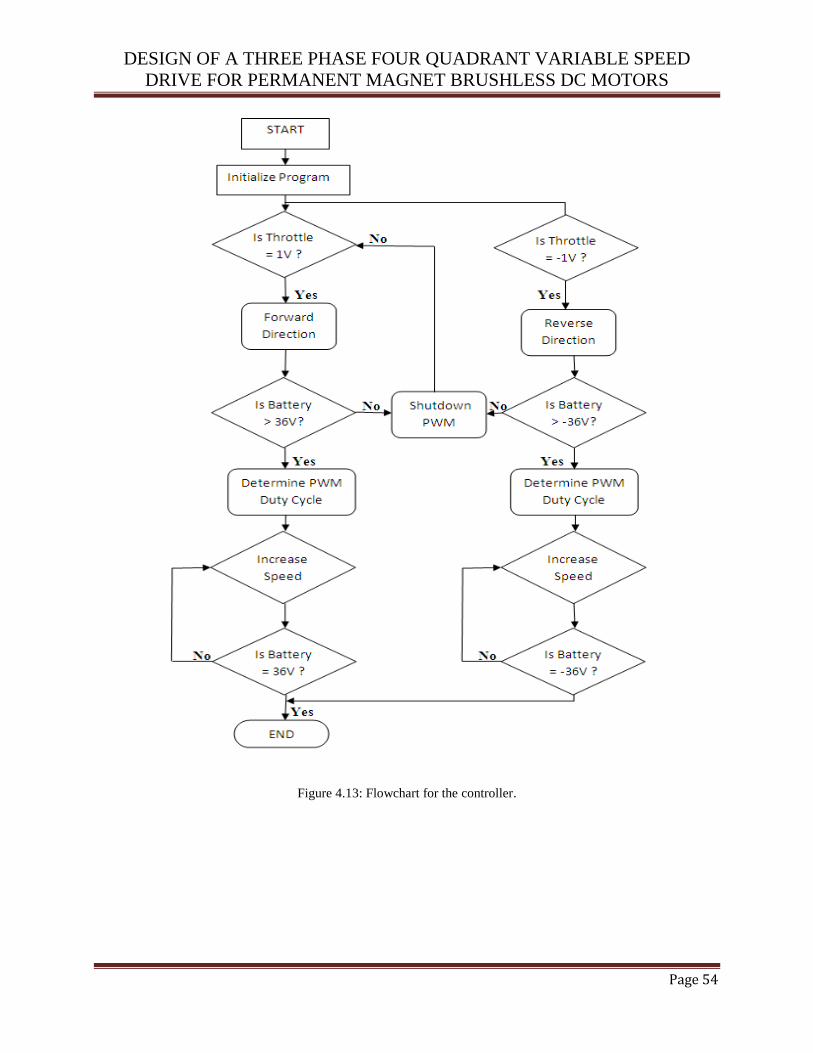
DESIGN OF A THREE PHASE FOUR QUADRANT VARIABLE SPEED
DRIVE FOR PERMANENT MAGNET BRUSHLESS DC MOTORS
Page 54
Figure 4.13: Flowchart for the controller.
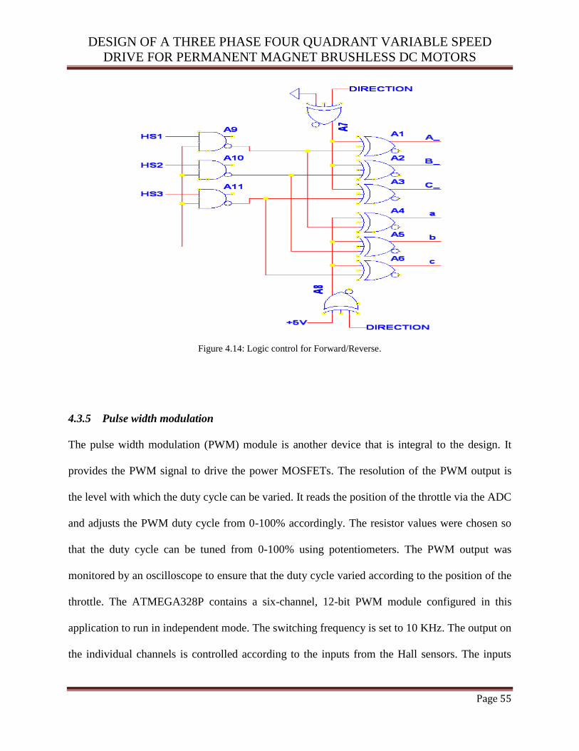
DESIGN OF A THREE PHASE FOUR QUADRANT VARIABLE SPEED
DRIVE FOR PERMANENT MAGNET BRUSHLESS DC MOTORS
Page 55
Figure 4.14: Logic control for Forward/Reverse.
4.3.5 Pulse width modulation
The pulse width modulation (PWM) module is another device that is integral to the design. It
provides the PWM signal to drive the power MOSFETs. The resolution of the PWM output is
the level with which the duty cycle can be varied. It reads the position of the throttle via the ADC
and adjusts the PWM duty cycle from 0-100% accordingly. The resistor values were chosen so
that the duty cycle can be tuned from 0-100% using potentiometers. The PWM output was
monitored by an oscilloscope to ensure that the duty cycle varied according to the position of the
throttle. The ATMEGA328P contains a six-channel, 12-bit PWM module configured in this
application to run in independent mode. The switching frequency is set to 10 KHz. The output on
the individual channels is controlled according to the inputs from the Hall sensors. The inputs

DESIGN OF A THREE PHASE FOUR QUADRANT VARIABLE SPEED
DRIVE FOR PERMANENT MAGNET BRUSHLESS DC MOTORS
Page 56
from the Hall sensors determine the sequence in which the three-phase bridge MOSFET is
switched. The duty cycle of the PWM is directly proportional to the accelerator potentiometer
input. The change in the duty cycle controls the current through the motor winding, thereby
controlling the motor torque.
The PWM modulation is performed by a six-channel timer/ pulse-width modulator (PWM)
module. The modulation techniques can be determined according to the motor supply voltage or
according to the switching of the MOSFETs. Unipolar control occurs when the motor detects
either the DC bus or zero voltage during one PWM cycle (Narayanan et al., 2006). The
ATMEGA328P PWM module can generate any type of PWM modulation technique for this
application. Another consideration is the correct back-EMF sensing. One of the requirements for
correct back- EMF sensing is that the back-EMF voltage is sensed when both semiconductor
switches are conducting (Trzynadlowski and Legowski, 1994). The ATMEGA328P is capable of
handling BLDC motor control with Hall sensors. There is a special mode in the capture and
compare mode that handles the commutation logic with minimal software. It can handle motors
with Hall sensors positioned 600 or 120
0 apart.
The trapezoidal control of a BLDC means that, at any time only two of the three phases are
energized whilst the other phase is kept floating (Kang and Sul, 1995). The slow decay method is
the usual modulation method where during the off period of the PWM, the load current is
allowed to circulate in the bottom switches. The fast decay method is when all the switches are
off during the off period of the PWM. To improve the efficiency of the system, the synchronous
rectification method can be used during high load. Instead of letting the load current circulate in
the body diode during the off PWM period; it is more efficient to let the current circulate in the
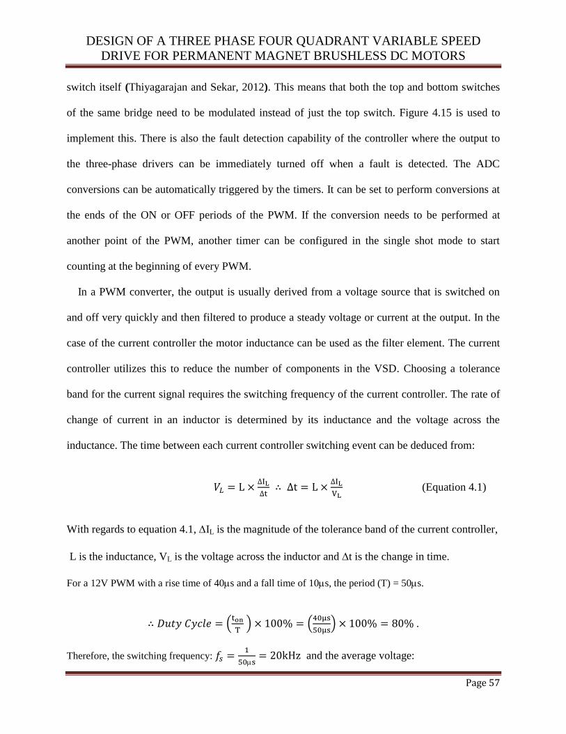
DESIGN OF A THREE PHASE FOUR QUADRANT VARIABLE SPEED
DRIVE FOR PERMANENT MAGNET BRUSHLESS DC MOTORS
Page 57
switch itself (Thiyagarajan and Sekar, 2012). This means that both the top and bottom switches
of the same bridge need to be modulated instead of just the top switch. Figure 4.15 is used to
implement this. There is also the fault detection capability of the controller where the output to
the three-phase drivers can be immediately turned off when a fault is detected. The ADC
conversions can be automatically triggered by the timers. It can be set to perform conversions at
the ends of the ON or OFF periods of the PWM. If the conversion needs to be performed at
another point of the PWM, another timer can be configured in the single shot mode to start
counting at the beginning of every PWM.
In a PWM converter, the output is usually derived from a voltage source that is switched on
and off very quickly and then filtered to produce a steady voltage or current at the output. In the
case of the current controller the motor inductance can be used as the filter element. The current
controller utilizes this to reduce the number of components in the VSD. Choosing a tolerance
band for the current signal requires the switching frequency of the current controller. The rate of
change of current in an inductor is determined by its inductance and the voltage across the
inductance. The time between each current controller switching event can be deduced from:
(Equation 4.1)
With regards to equation 4.1, IL is the magnitude of the tolerance band of the current controller,
L is the inductance, VL is the voltage across the inductor and t is the change in time.
For a 12V PWM with a rise time of 40s and a fall time of 10s, the period (T) = 50s.
(
) (
) .
Therefore, the switching frequency:
and the average voltage:
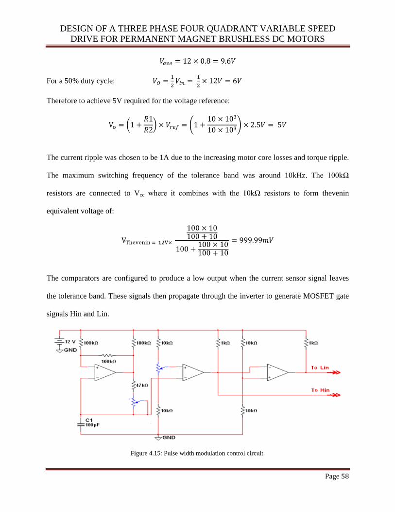
DESIGN OF A THREE PHASE FOUR QUADRANT VARIABLE SPEED
DRIVE FOR PERMANENT MAGNET BRUSHLESS DC MOTORS
Page 58
For a 50% duty cycle:
Therefore to achieve 5V required for the voltage reference:
(
) (
)
The current ripple was chosen to be 1A due to the increasing motor core losses and torque ripple.
The maximum switching frequency of the tolerance band was around 10kHz. The 100kΩ
resistors are connected to Vcc where it combines with the 10kΩ resistors to form thevenin
equivalent voltage of:
The comparators are configured to produce a low output when the current sensor signal leaves
the tolerance band. These signals then propagate through the inverter to generate MOSFET gate
signals Hin and Lin.
Figure 4.15: Pulse width modulation control circuit.

DESIGN OF A THREE PHASE FOUR QUADRANT VARIABLE SPEED
DRIVE FOR PERMANENT MAGNET BRUSHLESS DC MOTORS
Page 59
4.3.6 Current controller
The brushless DC motor with trapezoidal torque characteristic is used in this application. It has
high permeability permanent magnets on the rotor and a 3-phase, star-connected stator winding,
which derives its power from a standard 3-phase pulse width modulated (PWM) inverter. The
current controller controls the commutation of current from one motor phase to another, based on
rotor position information. The current during an active phase of a BLDC motor is proportional
to the torque produced by it. The VSD controls the output torque and therefore the current of the
motor in the drive system. In order to maintain high efficiency, a switching converter design is
used in the controller which requires an output filter to produce steady currents or voltages.
Control of the exact current magnitude is achieved using one of the following three methods:
Constant-frequency peak detecting, with turn on determine by the clock pulse time.
Tolerance band control.
Constant-“off”-time, peak detection control.
Tolerance band current control is used in the design of our current controller in this design.
Table 4.1 compares the three current control schemes with the requirements of BLDC motor
control. In the above current control schemes, the current can change at a very low rate, which
can lead to a large deviation in the precision of switching sequence. The switching pattern can
contain a frequency that is undesirable. To alleviate this problem, the current slope compensation
technique is used to effectively increase the rate of change of current and restore the precision of
switching events. The average current mode control applies the principle behind slope
compensation to obtain better performance over a wide range of current.
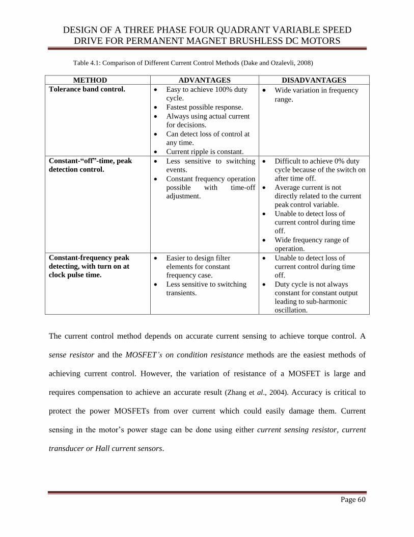
DESIGN OF A THREE PHASE FOUR QUADRANT VARIABLE SPEED
DRIVE FOR PERMANENT MAGNET BRUSHLESS DC MOTORS
Page 60
Table 4.1: Comparison of Different Current Control Methods (Dake and Ozalevli, 2008)
METHOD ADVANTAGES DISADVANTAGES
Tolerance band control.
Easy to achieve 100% duty
cycle.
Fastest possible response.
Always using actual current
for decisions.
Can detect loss of control at
any time.
Current ripple is constant.
Wide variation in frequency
range.
Constant-“off”-time, peak
detection control.
Less sensitive to switching
events.
Constant frequency operation
possible with time-off
adjustment.
Difficult to achieve 0% duty
cycle because of the switch on
after time off.
Average current is not
directly related to the current
peak control variable.
Unable to detect loss of
current control during time
off.
Wide frequency range of
operation. Constant-frequency peak
detecting, with turn on at
clock pulse time.
Easier to design filter
elements for constant
frequency case.
Less sensitive to switching
transients.
Unable to detect loss of
current control during time
off.
Duty cycle is not always
constant for constant output
leading to sub-harmonic
oscillation.
The current control method depends on accurate current sensing to achieve torque control. A
sense resistor and the MOSFET’s on condition resistance methods are the easiest methods of
achieving current control. However, the variation of resistance of a MOSFET is large and
requires compensation to achieve an accurate result (Zhang et al., 2004). Accuracy is critical to
protect the power MOSFETs from over current which could easily damage them. Current
sensing in the motor’s power stage can be done using either current sensing resistor, current
transducer or Hall current sensors.
DESIGN OF A THREE PHASE FOUR QUADRANT VARIABLE SPEED
DRIVE FOR PERMANENT MAGNET BRUSHLESS DC MOTORS
Page 61
Hall-effect current sensors measure the current flowing through a conductor over a wide
frequency range. They can be used to determine the current flowing by measuring the magnetic
field created by the flowing current. The Hall sensors lack sensitivity and stability over
temperature (Dixon and Leal, 2002). A current transducer is also a form of current sensor with
built-in electronic interface that provides a digital or analog output signal. These are very simple
to use as there is no need to design interface and op-amp circuits as these are included in one
integrated circuit. Resistor current sensing is usually used for lower power motor controls. This
is the cheapest way of measuring motor current. It is achieved by placing a resistor in series with
the current to be measured and reading the voltage developed across the resistor.
The resistance of a current sensor resistor is very low and is usually rated to produce a voltage
in millivolts (Karthikegan and Sekaran, 2011). Electromagnetic interference (EMI) and noise can
occur due to the low voltage output of the sensor and the high gain amplifier required. Therefore
low pass filters can be used in the amplifier design as shown in Figure 4.16. Op-amps are used to
amplify the voltage developed across the resistor to the maximum level as indicated in Figure
4.17. The VSD is designed to operate at a maximum of 1.5kW. For a battery voltage of 36V and
50V, the required current capability of the VSD is:
(Equation 4.2)
For the BLDC motor having a power rating of 500W used in this application, the sensing resistor
current will range from of 10A to 14A.
The PMBLDC motor is first connected to the phase switcher module which uses the six power
MOSFETs to transform the motor phase connections into DC motor armature connections. The
DESIGN OF A THREE PHASE FOUR QUADRANT VARIABLE SPEED
DRIVE FOR PERMANENT MAGNET BRUSHLESS DC MOTORS
Page 62
current sense module is placed after the phase switcher to simplify measurement and
interpretation of the current signal. A specialized 5mΩ resistor sensor was used to sense the
current flowing through the motor. This single resistor method eliminates the problem of
balancing gains experienced with multi-sensor methods. The size advantage makes it an ideal
component of controller designed for electric bicycles, robotic or aerospace applications.
However, some noise is injected into the current signal and the entire current control requires
current filter design to ensure good performance. The current controller module is designed to
receive a single voltage signal that represents the current. A 500mA change in motor current
should cause a 50mV change in the voltage signal from the sensor (Dake and Ozalevli, 2008).
The resistors are chosen to create a potential divider on the non-inverting input of the operational
amplifier since the output is in phase with input therefore the XOR is used to invert the output
signals and the feedback resistor is used to determine gain of the system. Since the motor control
is capable of regeneration, current must be measured in both directions. The maximum power
dissipation for a maximum motor current is:
The FDP3632 MOSFETs used have a nominal turn on resistance of 9mΩ which cause them
to dissipate twice the power that the sense resistor dissipates at the same current level. The sense
resistor had a maximum power dissipation of 5W and the voltage across the resistor per amp is
5mV/A. The amplifier gain Av can then be calculated as:
WmARIP sense 5.45302max
2
max
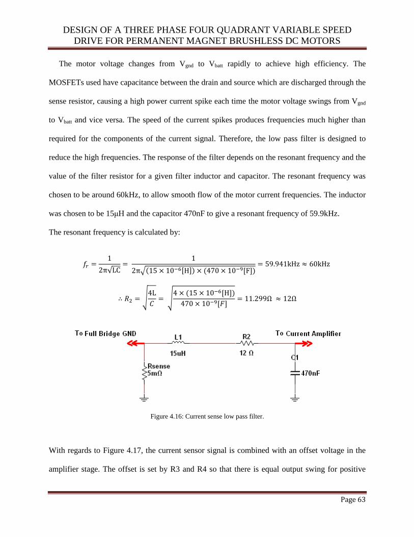
DESIGN OF A THREE PHASE FOUR QUADRANT VARIABLE SPEED
DRIVE FOR PERMANENT MAGNET BRUSHLESS DC MOTORS
Page 63
The motor voltage changes from Vgnd to Vbatt rapidly to achieve high efficiency. The
MOSFETs used have capacitance between the drain and source which are discharged through the
sense resistor, causing a high power current spike each time the motor voltage swings from Vgnd
to Vbatt and vice versa. The speed of the current spikes produces frequencies much higher than
required for the components of the current signal. Therefore, the low pass filter is designed to
reduce the high frequencies. The response of the filter depends on the resonant frequency and the
value of the filter resistor for a given filter inductor and capacitor. The resonant frequency was
chosen to be around 60kHz, to allow smooth flow of the motor current frequencies. The inductor
was chosen to be 15μH and the capacitor 470nF to give a resonant frequency of 59.9kHz.
The resonant frequency is calculated by:
√
√
√
√
Figure 4.16: Current sense low pass filter.
With regards to Figure 4.17, the current sensor signal is combined with an offset voltage in the
amplifier stage. The offset is set by R3 and R4 so that there is equal output swing for positive
DESIGN OF A THREE PHASE FOUR QUADRANT VARIABLE SPEED
DRIVE FOR PERMANENT MAGNET BRUSHLESS DC MOTORS
Page 64
and negative currents in sensor. The gain is set by the feedback resistor R6 so that ±30A can be
measured by the amplifier. The throttle input used varies from 1V to 5V with higher voltages
corresponding to higher or more positive demand torque. Therefore, the amplifier should be able
to produce a more positive output for higher machine currents and this requires a non inverting
amplifier configuration. The gain of the amplifier should be 10 as calculated. By setting R1 equal
to R2, the offset voltage can be calculated as:
(Equation 4.3)
The resistors R1 and R2 are made equal to create a thevenin equivalent voltage source with an
open terminal voltage of
and internal resistance
or
, since R1 = R2.
The comparator uses an external resistor network to achieve Schmitt trigger operation. The
strength of the positive feedback in the comparator, configured as a Schmitt trigger determines
the difference between the input threshold and the tolerance band. The four quadrant controller
has two comparators (cf. Figure 4.17) each managing a pair of thresholds. The Vhigh and Vlow
thresholds are set with R6. The lower resistance R5 increases the difference between the
thresholds that comparator switches at, producing Vhigh and Vlow.

DESIGN OF A THREE PHASE FOUR QUADRANT VARIABLE SPEED
DRIVE FOR PERMANENT MAGNET BRUSHLESS DC MOTORS
Page 65
Figure 4.17: Current amplifier (The resistors R1, R2, R3, R4 and C1are typical values selected from the application
of the TLV3502 comparator datasheet from Texas Instruments).
The current source half bridge is connected to the phase switcher power stage as shown in
Figure 4.18. The sense resistor is positioned so that the load or motor current always flows
through it. The half bridge applies Vbattery or Vgrnd to the phase switcher to increase or decrease
Ibldc. Vbldc is effectively the average value of the half bridge output. The current controller
interprets the current sensor signal and the throttle signal to control the MOSFETs QCH and
QCL (cf. Figure 4.18). They are used to apply a voltage to the BLDC motor through the phase
switcher so that the current in the motor flows to the current demanded by the throttle signal.
Figure 4.18 shows the position of QCH and QCL relative to the phase switcher and the supply.
The voltage Vbldc, across the phase switcher is determined by Vbattery and the state of QCH and
QCL.
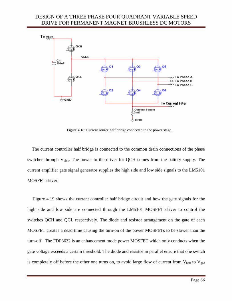
DESIGN OF A THREE PHASE FOUR QUADRANT VARIABLE SPEED
DRIVE FOR PERMANENT MAGNET BRUSHLESS DC MOTORS
Page 66
Figure 4.18: Current source half bridge connected to the power stage.
The current controller half bridge is connected to the common drain connections of the phase
switcher through Vbldc. The power to the driver for QCH comes from the battery supply. The
current amplifier gate signal generator supplies the high side and low side signals to the LM5101
MOSFET driver.
Figure 4.19 shows the current controller half bridge circuit and how the gate signals for the
high side and low side are connected through the LM5101 MOSFET driver to control the
switches QCH and QCL respectively. The diode and resistor arrangement on the gate of each
MOSFET creates a dead time causing the turn-on of the power MOSFETs to be slower than the
turn-off. The FDP3632 is an enhancement mode power MOSFET which only conducts when the
gate voltage exceeds a certain threshold. The diode and resistor in parallel ensure that one switch
is completely off before the other one turns on, to avoid large flow of current from Vbatt to Vgnd

DESIGN OF A THREE PHASE FOUR QUADRANT VARIABLE SPEED
DRIVE FOR PERMANENT MAGNET BRUSHLESS DC MOTORS
Page 67
during switching. The FDP3632 MOSFET has a breakdown voltage of 100V, a current rating of
90A, and a turn on resistance of 9mΩ. This gives it approximately a safety factor of two when
handling the current and voltage requirements of the controller (Dixon and Leal, 2002). The
LM5101 driver matches the breakdown voltage of the FDP3632 and provides up to 3A to drive
the MOSFET gate. Suitable resistor and capacitor values are chosen according to the datasheet to
create a uniform dead-time between the MOSFETs and the drivers to avoid damaging the
MOSFEFs.
Figure 4.19: Current controller half bridge circuit.

DESIGN OF A THREE PHASE FOUR QUADRANT VARIABLE SPEED
DRIVE FOR PERMANENT MAGNET BRUSHLESS DC MOTORS
Page 68
4.3.7 Temperature control
The temperature sensor is required to generate a signal when a certain temperature has been
reached. The temperature sensor is implemented to detect excess heat levels from various
components. With the circuits attached to the material of the stator, the heat levels in the circuitry
and the motor becomes similar (Kim and Doose, 1997). Therefore, to work around this
constraint, the temperature sensor design was integrated into the phase switcher circuit. Each
phase switcher MOSFET has one logic gate with input signals from two position sensor signals.
The temperature cut out circuit shown in Figure 4.20 uses three 1N4154 high speed switching
diodes to simulate open collector outputs so that when the temperature threshold is reached all
the Hall sensor outputs are driven to logic low.
The temperature control circuit has the effect of switching off all the MOSFETs in the phase
switcher and prevents the electric motor from receiving any power from the battery. The
temperature sensor is built around the same multi-function gate as the phase switcher logic. The
SN74LVC1G58 from Texas instruments has input Schmitt triggers that give the temperature
sensor different cut out and re-enable thresholds (Texas Instruments, 2013). The resistance of the
thermistor decreases when it heats up causing the voltage at the input of the Schmitt trigger
inverter in Figure 4.20 to decrease.
The values of R1 and R2 (cf. Figure 4.20) are calculated for the case of a thermistor that has
10k resistance at 250C. To set the temperature trip points, the input thresholds of the gate and the
thermistor resistance at certain temperatures must be known. The temperature cut out point was
set at 750C and the re-enable point was set at 40
0C to ensure that the system had properly cooled

DESIGN OF A THREE PHASE FOUR QUADRANT VARIABLE SPEED
DRIVE FOR PERMANENT MAGNET BRUSHLESS DC MOTORS
Page 69
off before attempting operation again. The input thresholds for the logic gate were obtained by
information in the data sheet; typical values were estimated to be 0.54Vcc for the rising threshold
and 0.37Vcc for the falling threshold. The relationship of temperature to resistance in the
thermistor was calculated using the Steinhart-Hart thermistor equation:
3
(Equation 4.4)
With regards to equation 4.4, A, B and C are constant coefficients, T is the temperature on the
Kelvin scale and R is the resistance of the thermistor in Ohms. At 750C, the resistance of the
10kΩ thermistor was ≈ 1.2kΩ and at 400C the resistance was ≈ 4.3kΩ. The voltage at the input in
Figure 4.20 can be calculated using the potential divider equation:
in
CC
2 thermistor
1 2 thermistor
(Equation 4.5)
The temperature cut out point varies from 1000C to 60
0C, while the re-enable temperature varies
from 400C to 55
0C.
Figure 4.20: The temperature cut-out circuit.

DESIGN OF A THREE PHASE FOUR QUADRANT VARIABLE SPEED
DRIVE FOR PERMANENT MAGNET BRUSHLESS DC MOTORS
Page 70
4.3.8 Speed limitation
A speed limiting circuit was designed to limit the motor speed to 500 RPM. This was necessary
in order to prevent the controller from being overdriven. Infrared transmitter and receiver sensors
were used to detect the number of revolutions per minute. The output from the sensor is a square
wave pulse with a frequency proportional to the motor speed. The pulse is fed directly into the
microcontroller and the speed is determined by measuring the frequency.
Therefore the LM2917 frequency to voltage converter is used to convert the frequency input
into a voltage that can be measured by the microcontrollers ADC. The LM2917 tachometer IC
from Texas Instruments is designed for a minimum external part count. The first stage of
operation is a differential amplifier driving a positive feedback flip-flop circuit (Texas
Instrument, 2013). The input threshold voltage is the amount of differential input voltage at
which the output of this stage changes state. The differential input gives the option of setting the
input switching level and still have the hysteresis for good noise rejection in any application.
The input stage is the bootstrap capacitor which converts the input frequency to a dc voltage.
This requires a timing capacitor, one output resistor, and an integrating capacitor. Change in
input state due to a differential voltage input, causes the timing capacitor to charge or discharge
linearly between two voltages whose difference is Vcc/2. Then in one half cycle of the input
frequency the change in charge on the timing capacitor is equal to the algebraic product of 0.5Vcc
and C1. If the pulses of current are integrated with the filter capacitor, then:
out c 1 cc in 1 1
(Equation 4.6)
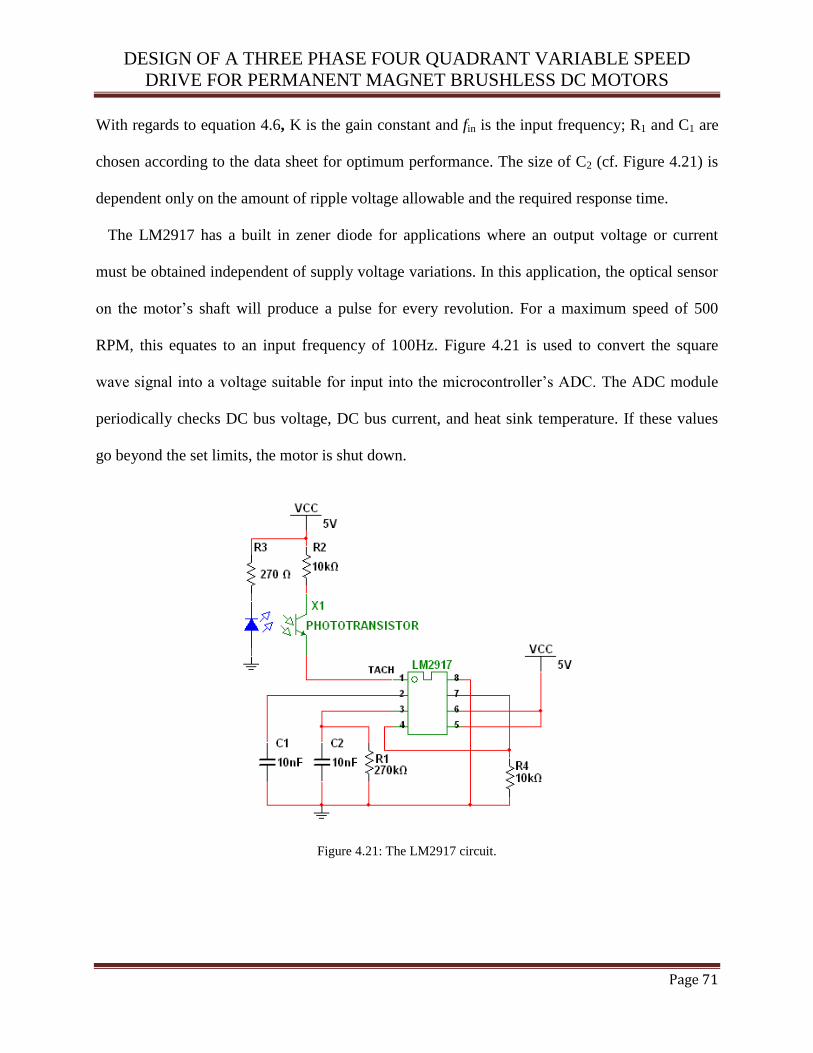
DESIGN OF A THREE PHASE FOUR QUADRANT VARIABLE SPEED
DRIVE FOR PERMANENT MAGNET BRUSHLESS DC MOTORS
Page 71
With regards to equation 4.6, K is the gain constant and fin is the input frequency; R1 and C1 are
chosen according to the data sheet for optimum performance. The size of C2 (cf. Figure 4.21) is
dependent only on the amount of ripple voltage allowable and the required response time.
The LM2917 has a built in zener diode for applications where an output voltage or current
must be obtained independent of supply voltage variations. In this application, the optical sensor
on the motor’s shaft will produce a pulse for every revolution. For a maximum speed of 500
RPM, this equates to an input frequency of 100Hz. Figure 4.21 is used to convert the square
wave signal into a voltage suitable for input into the microcontroller’s ADC. The ADC module
periodically checks DC bus voltage, DC bus current, and heat sink temperature. If these values
go beyond the set limits, the motor is shut down.
Figure 4.21: The LM2917 circuit.
DESIGN OF A THREE PHASE FOUR QUADRANT VARIABLE SPEED
DRIVE FOR PERMANENT MAGNET BRUSHLESS DC MOTORS
Page 72
4.3.9 Power supply design
The power supply required to run the variable speed drive’s control circuitry must be obtained
from the 36V battery pack. Power supply in the VSD is based on switch-mode regulator
approach. The battery voltage is stepped down to the MOSFET driver level by a switching
converter and then further reduced by linear regulators to provide power to analog and logic
devices. The control circuit requires 12VDC to drive the MOSFET gates and 5VDC for the rest
of the circuit with minimum power consumption.
The lead-acid battery pack used in this application has a maximum voltage of 36V when fully
charged, therefore the regulator must be able to operate at this maximum voltage level. A switch-
mode power supply is used to step the voltage down to 12V with minimal loss. The switch-
mode power supply has a low power dissipation compared to conventional linear regulator.
4.3.9.1 MOSFET driver supply
The MOSFET driver creates a high power gate drive signal from a low voltage input signal. The
driver integrated circuit (IC) only operates if the voltage supply to the output buffer is at the
maximum level that ensures complete switch ON of the MOSFET. The single chip switch-mode
power supply (SMPS) from Texas Instruments was selected to create a 12V supply for the
MOSFET drivers because it can operate with high input voltages with a low quiescent current.
The LM2576 from Texas Instruments was used to regulate the battery voltage down to the
required level for the MOSFET drivers. The LM2576 has an ON/OFF pin used to activate the
device. This pin has a Schmitt trigger which is activated by a positive voltage greater than 1.6V
(Texas Instruments, 2013) and only deactivated once the voltage at the pin falls 100mV below
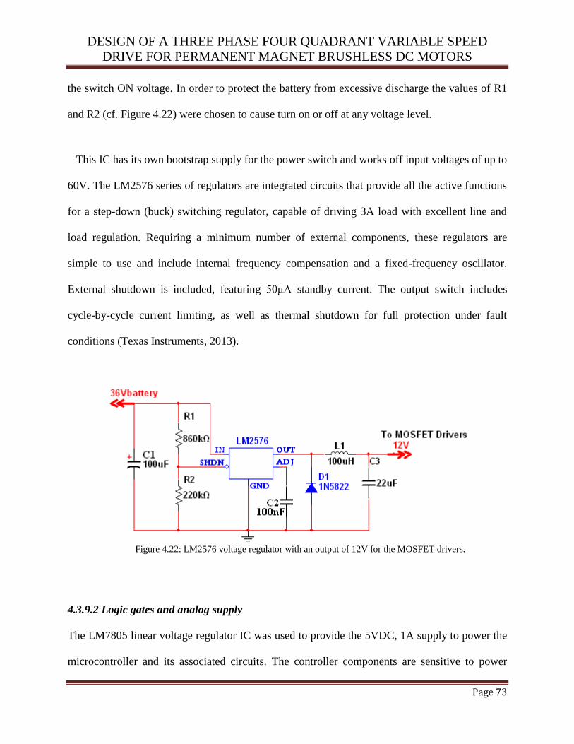
DESIGN OF A THREE PHASE FOUR QUADRANT VARIABLE SPEED
DRIVE FOR PERMANENT MAGNET BRUSHLESS DC MOTORS
Page 73
the switch ON voltage. In order to protect the battery from excessive discharge the values of R1
and R2 (cf. Figure 4.22) were chosen to cause turn on or off at any voltage level.
This IC has its own bootstrap supply for the power switch and works off input voltages of up to
60V. The LM2576 series of regulators are integrated circuits that provide all the active functions
for a step-down (buck) switching regulator, capable of driving 3A load with excellent line and
load regulation. Requiring a minimum number of external components, these regulators are
simple to use and include internal frequency compensation and a fixed-frequency oscillator.
External shutdown is included, featuring 50μA standby current. The output switch includes
cycle-by-cycle current limiting, as well as thermal shutdown for full protection under fault
conditions (Texas Instruments, 2013).
Figure 4.22: LM2576 voltage regulator with an output of 12V for the MOSFET drivers.
4.3.9.2 Logic gates and analog supply
The LM7805 linear voltage regulator IC was used to provide the 5VDC, 1A supply to power the
microcontroller and its associated circuits. The controller components are sensitive to power

DESIGN OF A THREE PHASE FOUR QUADRANT VARIABLE SPEED
DRIVE FOR PERMANENT MAGNET BRUSHLESS DC MOTORS
Page 74
supply variations especially if there are quick transients as in a switching regulator. The linear
regulator from Fairchild semiconductor was chosen for the purpose of powering the more
sensitive digital and analog circuitry. The MOSFET driver power supply provided a suitably low
voltage to energize the regulator. Figure 4.23 illustrates the circuit diagram of the 5VDC power
supply.
Figure 4.23: 5V Supply using LM7805 voltage regulator.
4.3.10 Regenerative braking
Regenerative braking occurs when the motor operates as a generator. Regenerative braking
brakes the motor by converting its mechanical energy into electrical energy and sending it back
to the batteries (Britten et al., 2007). During braking the PMBLDC motor will generate back
EMF which is rectified by the three phase full bridge phase switcher and filtered to DC voltage
to charge the battery. The back EMF produced is greater than the DC bus voltage in the second
quadrant of operation (Daniel and Patrick, 2012). This causes the current to reverse and oppose
the motor torque whilst the motor is running in the forward direction. For current to flow into
the battery, the DC bus voltage should be higher than the battery nominal voltage. The battery
types chosen for this project are lead acid with a nominal voltage of 12V and a 12AH capacity.
Current is usually lost as friction on the bicycle wheel during deceleration (Thiyagarajan and
Sekar, 2012) and the current amplifier (cf. Figure 4.17) is used to boost the current for
regeneration.
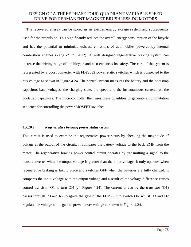
DESIGN OF A THREE PHASE FOUR QUADRANT VARIABLE SPEED
DRIVE FOR PERMANENT MAGNET BRUSHLESS DC MOTORS
Page 75
The recovered energy can be stored in an electric energy storage system and subsequently
used for the propulsion. This significantly reduces the overall energy consumption of the bicycle
and has the potential to minimize exhaust emissions of automobiles powered by internal
combustion engines (Zeng et al., 2012). A well designed regenerative braking system can
increase the driving range of the bicycle and also enhances its safety. The core of the system is
represented by a boost converter with FDP3632 power static switches which is connected to the
bus voltage as shown in Figure 4.24. The control system measures the battery and the bootstrap
capacitors bank voltages, the charging state, the speed and the instantaneous currents on the
bootstrap capacitors. The microcontroller then uses these quantities to generate a commutation
sequence for controlling the power MOSFET switches.
4.3.10.1 Regenerative braking power status circuit
This circuit is used to examine the regenerative power status by checking the magnitude of
voltage at the output of the circuit. It compares the battery voltage to the back EMF from the
motor. The regenerative braking power control circuit operates by transmitting a signal to the
boost converter when the output voltage is greater than the input voltage. It only operates when
regenerative braking is taking place and switches OFF when the batteries are fully charged. It
compares the input voltage with the output voltage and a result of the voltage difference causes
control transistor Q1 to turn ON (cf. Figure 4.24). The current driven by the transistor (Q1)
passes through R3 and R2 to ignite the gate of the FDP3632 to switch ON whilst D3 and D2
regulate the voltage at the gate to prevent over voltage as shown in Figure 4.24.

DESIGN OF A THREE PHASE FOUR QUADRANT VARIABLE SPEED
DRIVE FOR PERMANENT MAGNET BRUSHLESS DC MOTORS
Page 76
4.3.10.2 Boost converter design
The lack of economically priced energy storage device that provide high power density and high
energy density has been the main problem to the acceptance of electric vehicles and bicycles as
the main form of private and public transportation (Manoj et al., 2010). Therefore, there is a need
for an energy management supplementary system to back up the power systems of electric
drives. The electric bicycle in this project was powered with the 36V, 12Ah lead acid batteries
which require a boost converter to charge the batteries during long distance riding. The required
boost converter is shown in Figure 4.25. It can be operated in continuous current mode (CCM)
and discontinuous current mode (DCM). This converter function is based on pulse width
modulation (PWM). The PWM is sent from a microcontroller in order to control the FDP3632 to
switch ON or switch OFF.
When the converter is energized, the FDP3632 will be turned on by setting the PWM to high
(cf. Figure 4.25). This results in a positive voltage across the inductor, thus increasing the
inductor current linearly. The output capacitor will discharge through the load resistance in order
to provide continuous supply to the load. When it de-energizes, the current through the inductor
will continue to flow in the same direction and therefore opposes any drop in current by
reversing its electromotive force (EMF). Inductor L1 will be treated as a voltage source which is
in series with the input voltage. The energy stored in the inductor will add extra voltage to the
input voltage to boost the output voltage.
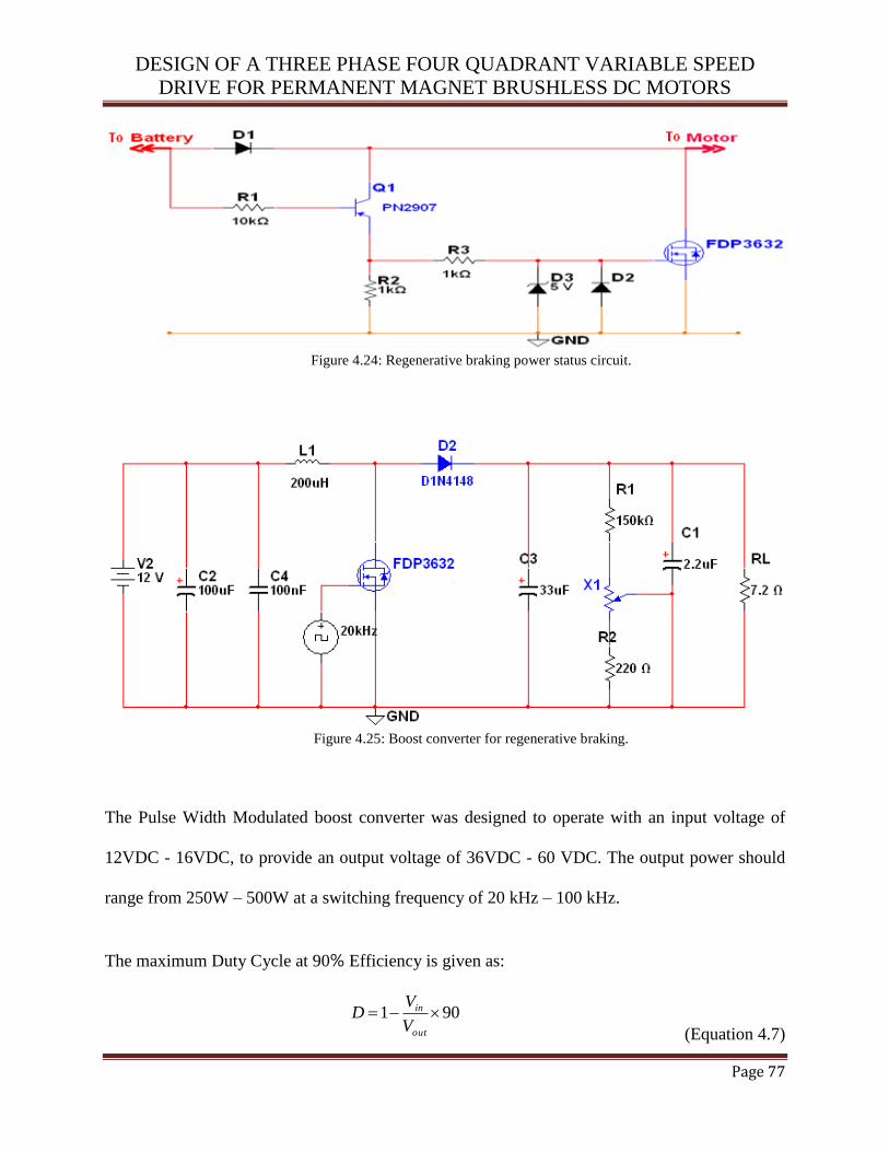
DESIGN OF A THREE PHASE FOUR QUADRANT VARIABLE SPEED
DRIVE FOR PERMANENT MAGNET BRUSHLESS DC MOTORS
Page 77
Figure 4.24: Regenerative braking power status circuit.
Figure 4.25: Boost converter for regenerative braking.
The Pulse Width Modulated boost converter was designed to operate with an input voltage of
12VDC - 16VDC, to provide an output voltage of 36VDC - 60 VDC. The output power should
range from 250W – 500W at a switching frequency of 20 kHz – 100 kHz.
The maximum Duty Cycle at 90% Efficiency is given as:
901 out
in
V
VD
(Equation 4.7)
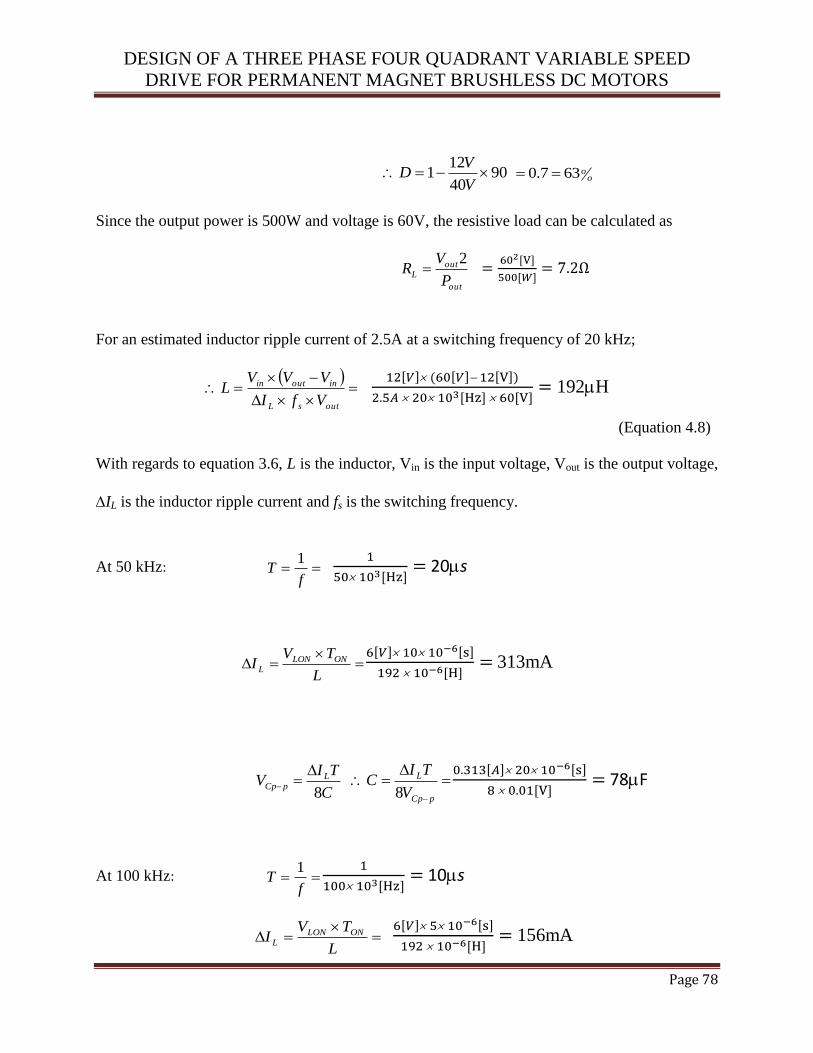
DESIGN OF A THREE PHASE FOUR QUADRANT VARIABLE SPEED
DRIVE FOR PERMANENT MAGNET BRUSHLESS DC MOTORS
Page 78
9040
121
V
VD o
o637.0
Since the output power is 500W and voltage is 60V, the resistive load can be calculated as
out
outL
P
VR
2
For an estimated inductor ripple current of 2.5A at a switching frequency of 20 kHz;
outsL
inoutin
VfI
VVVL
192H
(Equation 4.8)
With regards to equation 3.6, L is the inductor, Vin is the input voltage, Vout is the output voltage,
IL is the inductor ripple current and fs is the switching frequency.
At 50 kHz: f
T1
20s
L
TVI ONLON
L
313mA
C
TIV L
pCp8
pCp
L
V
TIC
8
78F
At 100 kHz: f
T1
10s
L
TVI ONLON
L
156mA
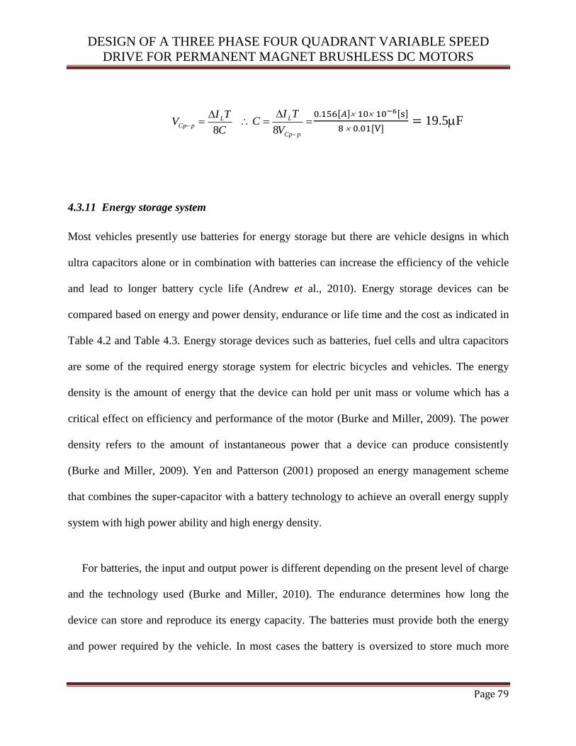
DESIGN OF A THREE PHASE FOUR QUADRANT VARIABLE SPEED
DRIVE FOR PERMANENT MAGNET BRUSHLESS DC MOTORS
Page 79
C
TIV L
pCp8
pCp
L
V
TIC
8
19.5F
4.3.11 Energy storage system
Most vehicles presently use batteries for energy storage but there are vehicle designs in which
ultra capacitors alone or in combination with batteries can increase the efficiency of the vehicle
and lead to longer battery cycle life (Andrew et al., 2010). Energy storage devices can be
compared based on energy and power density, endurance or life time and the cost as indicated in
Table 4.2 and Table 4.3. Energy storage devices such as batteries, fuel cells and ultra capacitors
are some of the required energy storage system for electric bicycles and vehicles. The energy
density is the amount of energy that the device can hold per unit mass or volume which has a
critical effect on efficiency and performance of the motor (Burke and Miller, 2009). The power
density refers to the amount of instantaneous power that a device can produce consistently
(Burke and Miller, 2009). Yen and Patterson (2001) proposed an energy management scheme
that combines the super-capacitor with a battery technology to achieve an overall energy supply
system with high power ability and high energy density.
For batteries, the input and output power is different depending on the present level of charge
and the technology used (Burke and Miller, 2010). The endurance determines how long the
device can store and reproduce its energy capacity. The batteries must provide both the energy
and power required by the vehicle. In most cases the battery is oversized to store much more
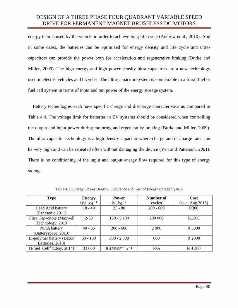
DESIGN OF A THREE PHASE FOUR QUADRANT VARIABLE SPEED
DRIVE FOR PERMANENT MAGNET BRUSHLESS DC MOTORS
Page 80
energy than is used by the vehicle in order to achieve long life cycle (Andrew et al., 2010). And
in some cases, the batteries can be optimized for energy density and life cycle and ultra-
capacitors can provide the power both for acceleration and regenerative braking (Burke and
Miller, 2009). The high energy and high power density ultra-capacitors are a new technology
used in electric vehicles and bicycles. The ultra-capacitor system is comparable to a fossil fuel or
fuel cell system in terms of input and out power of the energy storage system.
Battery technologies each have specific charge and discharge characteristics as compared in
Table 4.4. The voltage limit for batteries in EV systems should be considered when controlling
the output and input power during motoring and regenerative braking (Burke and Miller, 2009).
The ultra-capacitor technology is a high density capacitor where charge and discharge rates can
be very high and can be repeated often without damaging the device (Yen and Patterson, 2001).
There is no conditioning of the input and output energy flow required for this type of energy
storage.
Table 4.2: Energy, Power Density, Endurance and Cost of Energy storage System
Type Energy
Power
Number of
cycles
Cost
(as at Aug.2015)
Lead Acid battery
(Panasonic,2011)
18 - 40 25 - 80 200 - 600 R300
Ultra Capacitors (Maxwell
Technology, 2013
2-30 150 - 5 100 200 000 R1500
Nimh battery
(Batteryspace, 2013)
40 - 85 200 - 600 2 000 R 3000
Li-polymer battery (Dixon
Batteries, 2013)
60 - 130 300 - 2 800 600 R 2000
H2fuel Cell2 (Ebay, 2014) 33 600 N/A R 4 380
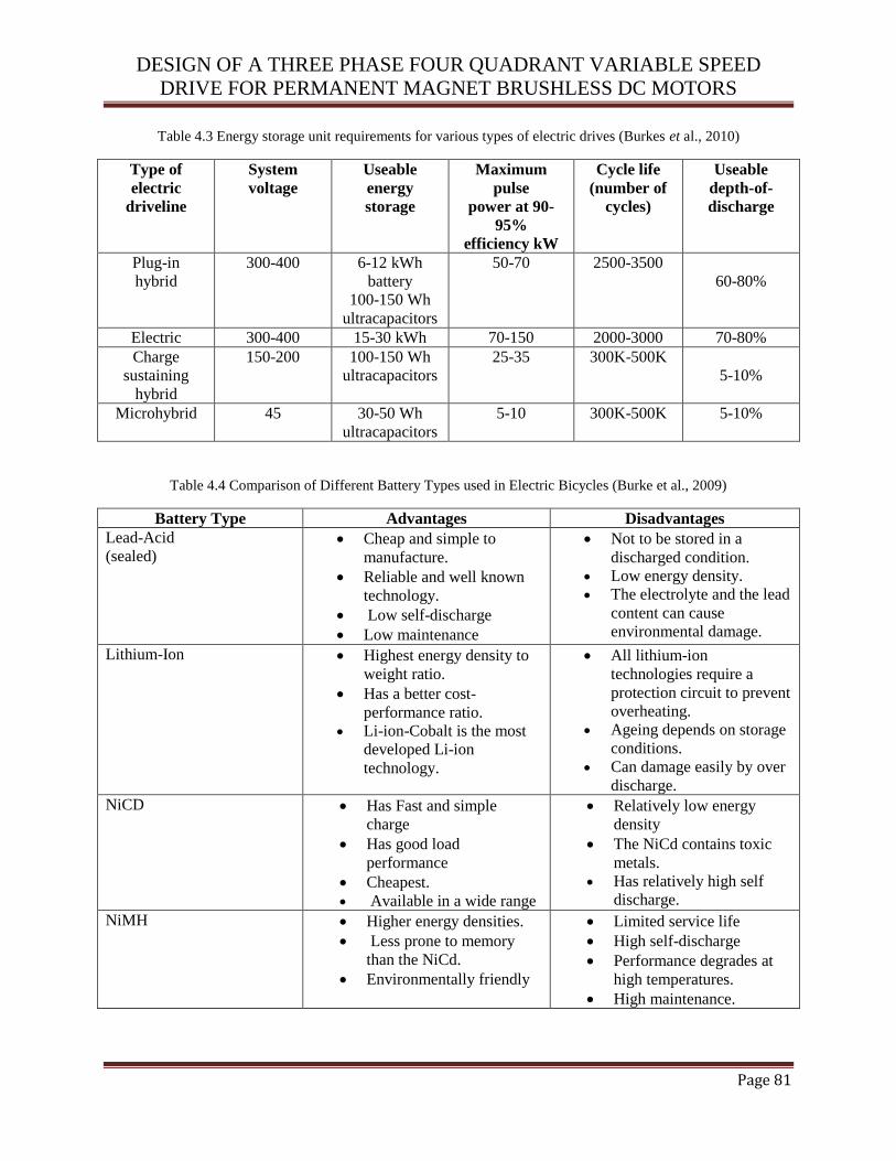
DESIGN OF A THREE PHASE FOUR QUADRANT VARIABLE SPEED
DRIVE FOR PERMANENT MAGNET BRUSHLESS DC MOTORS
Page 81
Table 4.3 Energy storage unit requirements for various types of electric drives (Burkes et al., 2010)
Type of
electric
driveline
System
voltage
Useable
energy
storage
Maximum
pulse
power at 90-
95%
efficiency kW
Cycle life
(number of
cycles)
Useable
depth-of-
discharge
Plug-in
hybrid
300-400 6-12 kWh
battery
100-150 Wh
ultracapacitors
50-70 2500-3500
60-80%
Electric 300-400 15-30 kWh 70-150 2000-3000 70-80%
Charge
sustaining
hybrid
150-200 100-150 Wh
ultracapacitors
25-35 300K-500K
5-10%
Microhybrid 45 30-50 Wh
ultracapacitors
5-10 300K-500K 5-10%
Table 4.4 Comparison of Different Battery Types used in Electric Bicycles (Burke et al., 2009)
Battery Type Advantages Disadvantages
Lead-Acid
(sealed) Cheap and simple to
manufacture.
Reliable and well known
technology.
Low self-discharge
Low maintenance
Not to be stored in a
discharged condition.
Low energy density.
The electrolyte and the lead
content can cause
environmental damage.
Lithium-Ion Highest energy density to
weight ratio.
Has a better cost-
performance ratio.
Li-ion-Cobalt is the most
developed Li-ion
technology.
All lithium-ion
technologies require a
protection circuit to prevent
overheating.
Ageing depends on storage
conditions.
Can damage easily by over
discharge.
NiCD Has Fast and simple
charge
Has good load
performance
Cheapest.
Available in a wide range
Relatively low energy
density
The NiCd contains toxic
metals.
Has relatively high self
discharge.
NiMH Higher energy densities.
Less prone to memory
than the NiCd.
Environmentally friendly
Limited service life
High self-discharge
Performance degrades at
high temperatures.
High maintenance.
DESIGN OF A THREE PHASE FOUR QUADRANT VARIABLE SPEED
DRIVE FOR PERMANENT MAGNET BRUSHLESS DC MOTORS
Page 82
4.3.12 Thermal design
The thermal design section discusses the calculations of power dissipation and losses to ensure
the devices operate within specification to maximize reliability. Conduction losses in both the
high and low side of the bridge are calculated. Cooling is also implemented with the use of heat-
sinks. Heat is the ultimate cause of all power MOSFET failures due to an electrical overstress of
the device, extreme temperature and high peak power cycling (Agilent Technologies, 2008).
Electrical overstress failures are caused by operating the device outside its safe operating limits.
A power cycling failure involves mechanical and thermal stresses on the device experienced due
to a low pulse width modulation duty cycle.
Changes in temperature cause materials in the device to expand and contract. Due to the range
of materials used in the device, some parts have different coefficients of thermal expansion
compared to others. This cyclic expansion and contraction can cause stresses at the interface
between two different materials. The faster the change in temperature, the greater will be the
stresses. In normal operation, the amount of power lost as heat can be estimated using
specifications from the data sheets and this will determine the amount of cooling required.
The heat-sink required is determined by the conduction and switching losses in the power
MOSFETs, the maximum junction temperature and power dissipation. The control system
steady-state condition was analysed to determine the thermal characteristics of the design.
Power dissipation in all the various components was calculated to ensure that the heat generated
by the power MOSFETs is equal to the heat absorbed by the heat-sinks. The components data
sheets give specifications of the thermal resistance of the semiconductors junction-to-package
which gives the ability of the component to conduct heat away from the junction.
DESIGN OF A THREE PHASE FOUR QUADRANT VARIABLE SPEED
DRIVE FOR PERMANENT MAGNET BRUSHLESS DC MOTORS
Page 83
4.3.12.1 Power dissipation calculations
The conduction loss in the power MOSFET is caused by the drain-to-source ON resistance of the
MOSFETs and switching losses caused by the switching ON and OFF periods of the
MOSFETs. The GWM 100-01X1 has a maximum drain-to-source resistance (RDS(on)) rating of
8.5mΩ with a minimum of 7.5mΩ. The conduction losses can be calculated by the following
formula:
(Equation 4.9)
With regards to equation 4.9, PD is the power dissipation, D is the duty cycle of the MOSFET, ID
is the drain current and RDS(on) is the drain-to-source on resistance .
High power dissipation normally occurs when the MOSFETs are driven at 100% duty cycle.
The desired maximum current of 30A in motoring mode was used in the final design for the
electric bicycle. The maximum conduction losses for the high side MOSFETs at this current with
the maximum RDS(on) of 8.5mΩ is shown in equation 4.10:
(Equation 4.10)
With the high side of five MOSFETs, each MOSFET will dissipate 1.53W which is within the
maximum power dissipation rating of 10W. Each MOSFET carries 6A at the maximum current
of 30A which is below the MOSFETs maximum current rating of 90A. The regeneration current
will be limited to 15A to protect the batteries from overcharging. The conduction losses in the
low side of the full bridge can also be calculated as:

DESIGN OF A THREE PHASE FOUR QUADRANT VARIABLE SPEED
DRIVE FOR PERMANENT MAGNET BRUSHLESS DC MOTORS
Page 84
The low side of the bridge also consists of three MOSFETs which will dissipate 0.56W each.
This power is also within the maximum power dissipation of 10W. Since the actual value of
depends on the temperature variation of the device, it is necessary to include the
temperature coefficient of ) in the calculation. Therefore, the equation for conduction
losses at a specific temperature is given as:
(Equation 4.11)
With regards to equation 4.11, PD is the power dissipation, ID is the drain current, RDS(on) is the
drain-to-source on resistance, T is the temperature coefficient of in and D is the
duty cycle. The switching losses caused by the rise and fall times of the MOSFET are estimated
as follows:
(Equation 4.12)
With regards to equation 4.12, tr is the rise time, tf is the fall time, is the total gate charge,
is the gate drive current, is the inductance of driver to MOSFET connection, is the gate-to-
source voltage and denotes the gate turn on threshold (IXYS 2009). The switching losses
can be calculated as below if the rise and fall times are known:
( ) (Equation 4.13)
With regards to equation 4.13, PD is the power dissipation, is the drain current, is the input
source voltage tr is the rise time, tf is the fall time and f is the frequency of the PWM signal.

DESIGN OF A THREE PHASE FOUR QUADRANT VARIABLE SPEED
DRIVE FOR PERMANENT MAGNET BRUSHLESS DC MOTORS
Page 85
From the data sheet of the GWM 100-01X1 integrated circuit (IXYS, 2009), ID = 90A,
and . The power dissipation from the 5- MOSFET circuit is:
This is about 1W per MOSFET due to switching losses. Therefore the total conduction and
switching losses is 2.53W (1.53W + 1W) per MOSFET on the high side of the full bridge.
There are also power losses in the freewheeling diodes which occur in the low-side of the full
bridge when the circuit is operating at 50% duty cycle at an average current of 15A. The loss can
be estimated by the forward voltage drop of the diode and the current flowing through it as
follows:
(Equation 4.14)
With regards to equation 4.14, is the diode forward voltage and is the diode current. In
this application, the maximum diode loss is calculated as follows using VDS of 1.2V from the
datasheet:
The three diodes in the low side of the bridge will dissipate 6W each. The loss for the high side
diodes also occurs during regeneration with a current of 10A. Therefore the loss is calculated as
given below:
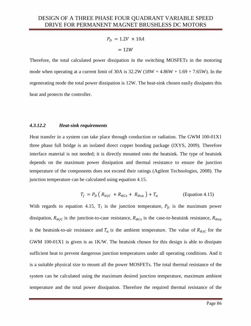
DESIGN OF A THREE PHASE FOUR QUADRANT VARIABLE SPEED
DRIVE FOR PERMANENT MAGNET BRUSHLESS DC MOTORS
Page 86
Therefore, the total calculated power dissipation in the switching MOSFETs in the motoring
mode when operating at a current limit of 30A is 32.2W (18W + 4.86W + 1.69 + 7.65W). In the
regenerating mode the total power dissipation is 12W. The heat-sink chosen easily dissipates this
heat and protects the controller.
4.3.12.2 Heat-sink requirements
Heat transfer in a system can take place through conduction or radiation. The GWM 100-01X1
three phase full bridge is an isolated direct copper bonding package (IXYS, 2009). Therefore
interface material is not needed; it is directly mounted onto the heatsink. The type of heatsink
depends on the maximum power dissipation and thermal resistance to ensure the junction
temperature of the components does not exceed their ratings (Agilent Technologies, 2008). The
junction temperature can be calculated using equation 4.15.
( ) (Equation 4.15)
With regards to equation 4.15, TJ is the junction temperature, is the maximum power
dissipation, is the junction-to-case resistance, is the case-to-heatsink resistance,
is the heatsink-to-air resistance and is the ambient temperature. The value of for the
GWM 100-01X1 is given is as 1K/W. The heatsink chosen for this design is able to dissipate
sufficient heat to prevent dangerous junction temperatures under all operating conditions. And it
is a suitable physical size to mount all the power MOSFETs. The total thermal resistance of the
system can be calculated using the maximum desired junction temperature, maximum ambient
temperature and the total power dissipation. Therefore the required thermal resistance of the
DESIGN OF A THREE PHASE FOUR QUADRANT VARIABLE SPEED
DRIVE FOR PERMANENT MAGNET BRUSHLESS DC MOTORS
Page 87
heat-sink for an estimated maximum power loss of 50W, a maximum ambient temperature of
25°C and maximum junction temperature of 150°C which is the maximum junction temperature
of the GWM 100-01X1is given as:
(Equation 4.16)
With regards to equation 4.16, is the total thermal resistance, Tmax is maximum junction
temperature, Ta is the maximum ambient temperature and PD is the power dissipation.
The thermal resistance is low which requires a quality heat-sink. Therefore the heat-sink chosen
for this design is the HS24 TO-3 solderable finish SMD heat-sink from Aavid Thermalloy. The
heat-sink is designed with a minimum thermal resistance.
4.4 SUMMARY AND CONCLUSIONS
The hardware implementation in this chapter describes the design of a 3-phase BLDC motor
drive system based on four quadrant operation method. The design is applicable to a wide range
of BLDC motors. Though the design is confined to an E-bike, the control system can be further
extended to other application areas which have a broad application prospects such as EV
systems. The following chapter will describe the simulation studies that were conducted to assess
the design of the proposed motor drive.

DESIGN OF A THREE PHASE FOUR QUADRANT VARIABLE SPEED
DRIVE FOR PERMANENT MAGNET BRUSHLESS DC MOTORS
Page 88
This page is intentionally blank

DESIGN OF A THREE PHASE FOUR QUADRANT VARIABLE SPEED
DRIVE FOR PERMANENT MAGNET BRUSHLESS DC MOTORS
Page 89
CHAPTER 5
SIMULATION STUDIES
5.1 INTRODUCTION
The PMBLDC motor and the proposed controller were simulated using the Linear Technology
Simulation Program with Integrated Circuit Emphasis (LTspice IV). LTspice IV is a high
performance SPICE simulator, schematic capture and waveform viewer with enhanced models
for the simulation of switching devices. Linear Technology provides a variety of custom design
simulation tools and device models to allow designers to quickly and easily evaluate circuits
using high performance switching regulators, amplifiers, data converters and filters. The
software was used to predict the operation of the VSD at any time during the control session. The
generated voltages of the BLDC motor and the Hall Effect position sensor signals were
simulated using periodic waveforms of different frequencies. The speed was varied to obtain
results at different speed levels.
5.2 VOLTAGE AND CURRENT CONTROL
Voltage control uses PWM of the dc bus voltage (V battery) for regulating the duty cycle and the
average back EMF of the motor. Current control utilizes tolerance band current control (cf.
section 4.3.6) to set the desired current level for the motor. Brushless DC motors with trapezoidal
back EMF have concentrated windings, discrete magnets with no skew, and thinner steel which
makes the motor inexpensive and easy to control (Colton, 2010).
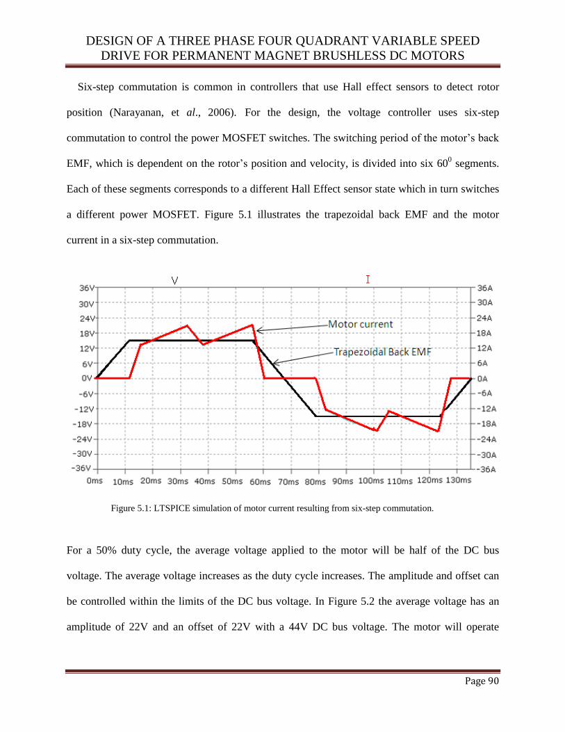
DESIGN OF A THREE PHASE FOUR QUADRANT VARIABLE SPEED
DRIVE FOR PERMANENT MAGNET BRUSHLESS DC MOTORS
Page 90
Six-step commutation is common in controllers that use Hall effect sensors to detect rotor
position (Narayanan, et al., 2006). For the design, the voltage controller uses six-step
commutation to control the power MOSFET switches. The switching period of the motor’s back
EMF, which is dependent on the rotor’s position and velocity, is divided into six 600 segments.
Each of these segments corresponds to a different Hall Effect sensor state which in turn switches
a different power MOSFET. Figure 5.1 illustrates the trapezoidal back EMF and the motor
current in a six-step commutation.
Figure 5.1: LTSPICE simulation of motor current resulting from six-step commutation.
For a 50% duty cycle, the average voltage applied to the motor will be half of the DC bus
voltage. The average voltage increases as the duty cycle increases. The amplitude and offset can
be controlled within the limits of the DC bus voltage. In Figure 5.2 the average voltage has an
amplitude of 22V and an offset of 22V with a 44V DC bus voltage. The motor will operate

DESIGN OF A THREE PHASE FOUR QUADRANT VARIABLE SPEED
DRIVE FOR PERMANENT MAGNET BRUSHLESS DC MOTORS
Page 91
within its parameters of maximum speed, torque, voltage and power if all the three phases have
the same offset. It will only detect the voltage difference between the phases.
Figure 5.2: LTSPICE simulation of the DC bus voltage and the average voltage at 25 kHz PWM.
The current controller pushes the back EMF to when a commutation occurs so that
builds up in the next active phase. Figure 5.3 indicates and for a BLDC
motor controlled with a fixed average voltage produced by PWM of with a constant duty
ratio. The torque was varied between the positive and negative maximum voltage in the
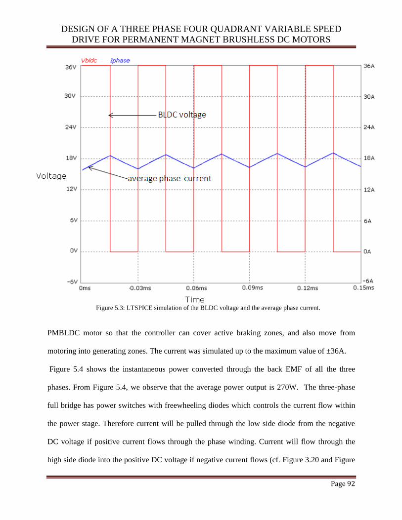
DESIGN OF A THREE PHASE FOUR QUADRANT VARIABLE SPEED
DRIVE FOR PERMANENT MAGNET BRUSHLESS DC MOTORS
Page 92
Figure 5.3: LTSPICE simulation of the BLDC voltage and the average phase current.
PMBLDC motor so that the controller can cover active braking zones, and also move from
motoring into generating zones. The current was simulated up to the maximum value of ±36A.
Figure 5.4 shows the instantaneous power converted through the back EMF of all the three
phases. From Figure 5.4, we observe that the average power output is 270W. The three-phase
full bridge has power switches with freewheeling diodes which controls the current flow within
the power stage. Therefore current will be pulled through the low side diode from the negative
DC voltage if positive current flows through the phase winding. Current will flow through the
high side diode into the positive DC voltage if negative current flows (cf. Figure 3.20 and Figure
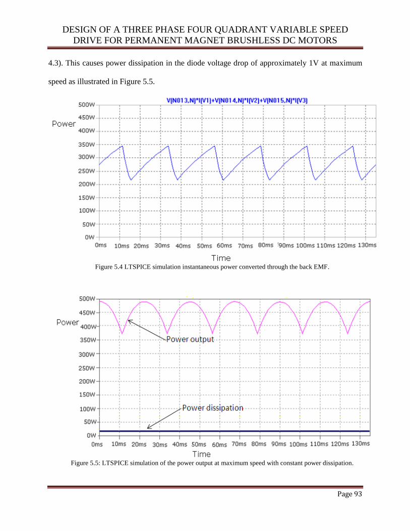
DESIGN OF A THREE PHASE FOUR QUADRANT VARIABLE SPEED
DRIVE FOR PERMANENT MAGNET BRUSHLESS DC MOTORS
Page 93
4.3). This causes power dissipation in the diode voltage drop of approximately 1V at maximum
speed as illustrated in Figure 5.5.
Figure 5.4 LTSPICE simulation instantaneous power converted through the back EMF.
Figure 5.5: LTSPICE simulation of the power output at maximum speed with constant power dissipation.
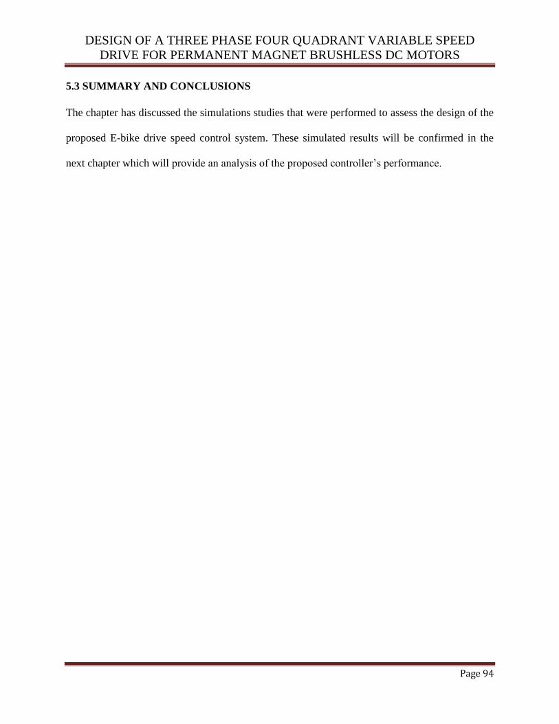
DESIGN OF A THREE PHASE FOUR QUADRANT VARIABLE SPEED
DRIVE FOR PERMANENT MAGNET BRUSHLESS DC MOTORS
Page 94
5.3 SUMMARY AND CONCLUSIONS
The chapter has discussed the simulations studies that were performed to assess the design of the
proposed E-bike drive speed control system. These simulated results will be confirmed in the
next chapter which will provide an analysis of the proposed controller’s performance.

DESIGN OF A THREE PHASE FOUR QUADRANT VARIABLE SPEED
DRIVE FOR PERMANENT MAGNET BRUSHLESS DC MOTORS
Page 95
This page is intentionally blank
DESIGN OF A THREE PHASE FOUR QUADRANT VARIABLE SPEED
DRIVE FOR PERMANENT MAGNET BRUSHLESS DC MOTORS
Page 96
CHAPTER 6
LIVE TEST RESULTS
6.1 INTRODUCTION AND EXPERIMENT SETUP
This section deals with the practical measurements of the variable speed drive (VSD). These
include the motor parameters, simulation and experimental measurements. The four quadrant
controller described in Chapter 4 was designed (cf. Appendix A) and built (cf. Figure 6.1) to
obtain the experimental results. The simulations were used as a guide for the design of the
hardware and the verification of the practical results for the entire design. The motor used in the
VSD for testing was a 500W, 36V, 409 hub motor mounted on a DH19 rim. The controller was
set up with a hub motor, lead acid battery pack, oscilloscope, multimeter and a throttle (cf.
Figure 6.1) to vary the speed for testing at different speed levels.
The controller was set at specific operating parameters which correspond with the PWM
outputs to test the various limits. Tests were conducted to ensure that the PWM signal output was
correct and varied in accordance with the position of the throttle when no current, speed or
voltage limits were exceeded. The throttle was varied from standstill to maximum speed and
different measurements were taken at different speeds. The currents and phase voltages were
measured at different operating points to ensure that the controller was safely operating in all
four quadrants.
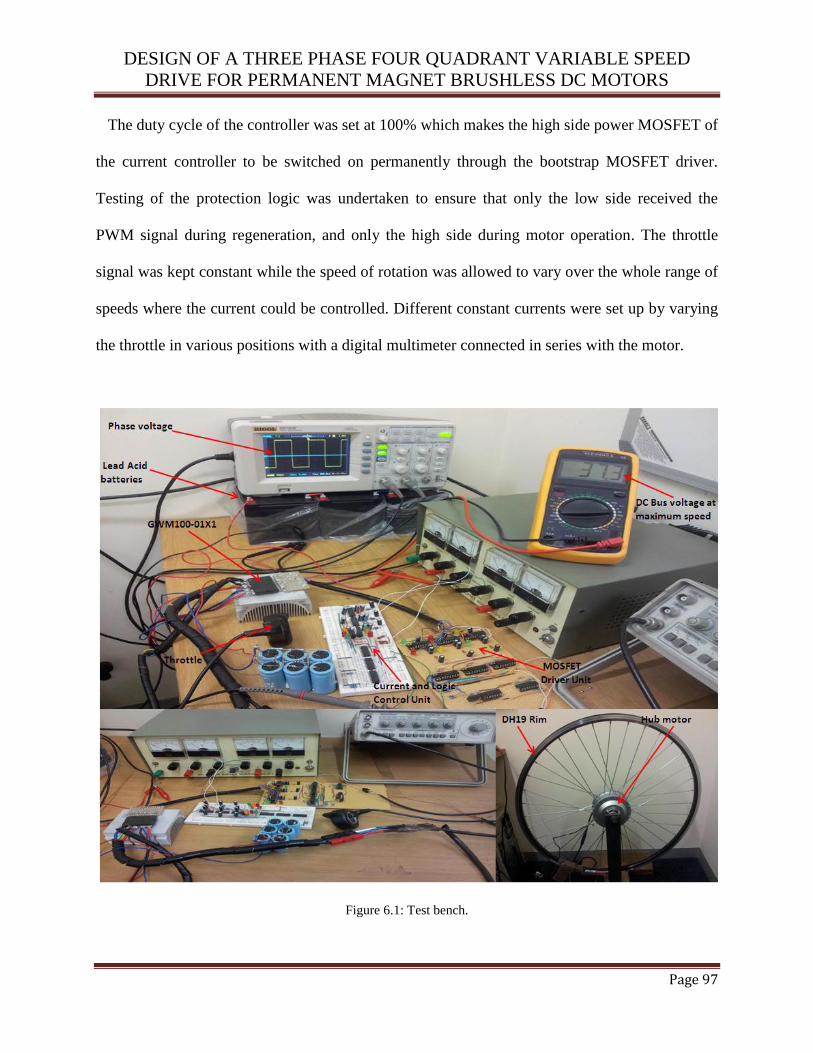
DESIGN OF A THREE PHASE FOUR QUADRANT VARIABLE SPEED
DRIVE FOR PERMANENT MAGNET BRUSHLESS DC MOTORS
Page 97
The duty cycle of the controller was set at 100% which makes the high side power MOSFET of
the current controller to be switched on permanently through the bootstrap MOSFET driver.
Testing of the protection logic was undertaken to ensure that only the low side received the
PWM signal during regeneration, and only the high side during motor operation. The throttle
signal was kept constant while the speed of rotation was allowed to vary over the whole range of
speeds where the current could be controlled. Different constant currents were set up by varying
the throttle in various positions with a digital multimeter connected in series with the motor.
Figure 6.1: Test bench.
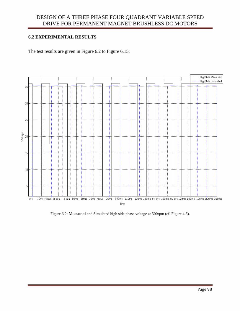
DESIGN OF A THREE PHASE FOUR QUADRANT VARIABLE SPEED
DRIVE FOR PERMANENT MAGNET BRUSHLESS DC MOTORS
Page 98
6.2 EXPERIMENTAL RESULTS
The test results are given in Figure 6.2 to Figure 6.15.
Figure 6.2: Measured and Simulated high side phase voltage at 500rpm (cf. Figure 4.8).
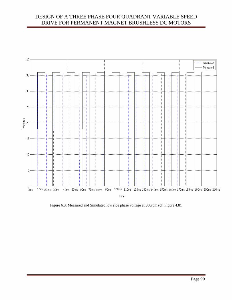
DESIGN OF A THREE PHASE FOUR QUADRANT VARIABLE SPEED
DRIVE FOR PERMANENT MAGNET BRUSHLESS DC MOTORS
Page 99
Figure 6.3: Measured and Simulated low side phase voltage at 500rpm (cf. Figure 4.8).
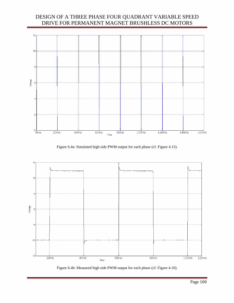
DESIGN OF A THREE PHASE FOUR QUADRANT VARIABLE SPEED
DRIVE FOR PERMANENT MAGNET BRUSHLESS DC MOTORS
Page 100
Figure 6.4a: Simulated high side PWM output for each phase (cf. Figure 4.15).
Figure 6.4b: Measured high side PWM output for each phase (cf. Figure 4.10).
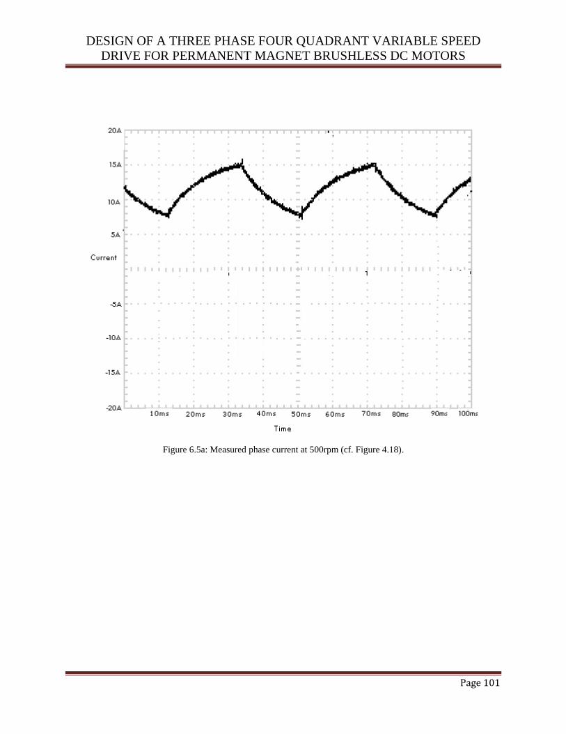
DESIGN OF A THREE PHASE FOUR QUADRANT VARIABLE SPEED
DRIVE FOR PERMANENT MAGNET BRUSHLESS DC MOTORS
Page 101
Figure 6.5a: Measured phase current at 500rpm (cf. Figure 4.18).
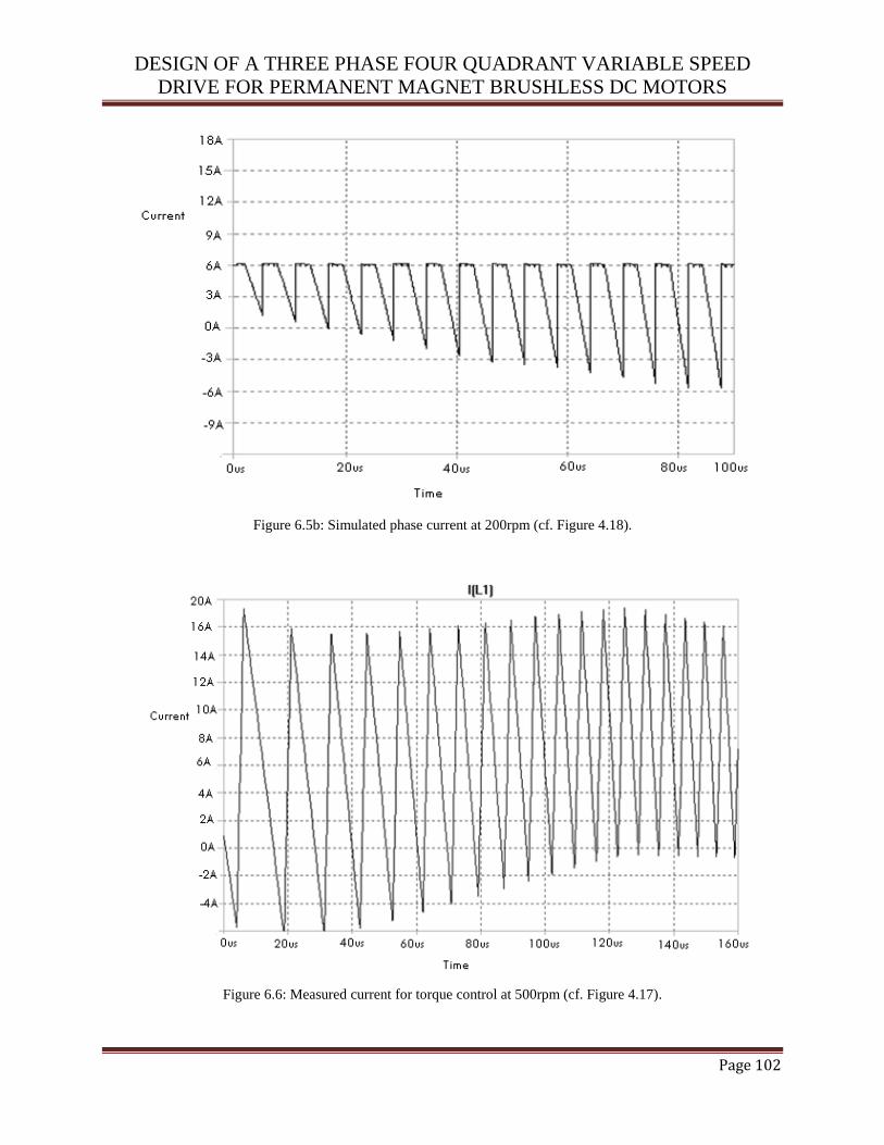
DESIGN OF A THREE PHASE FOUR QUADRANT VARIABLE SPEED
DRIVE FOR PERMANENT MAGNET BRUSHLESS DC MOTORS
Page 102
Figure 6.5b: Simulated phase current at 200rpm (cf. Figure 4.18).
Figure 6.6: Measured current for torque control at 500rpm (cf. Figure 4.17).
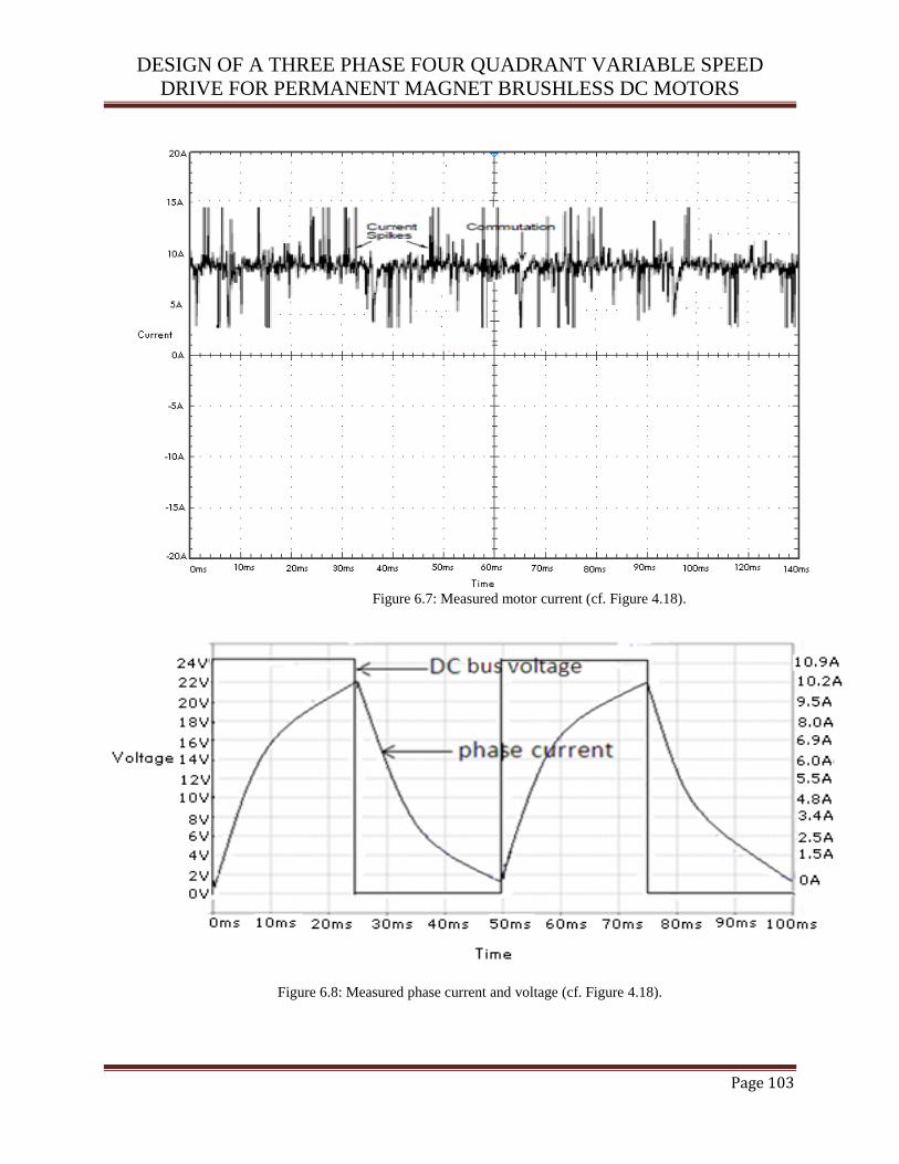
DESIGN OF A THREE PHASE FOUR QUADRANT VARIABLE SPEED
DRIVE FOR PERMANENT MAGNET BRUSHLESS DC MOTORS
Page 103
Figure 6.7: Measured motor current (cf. Figure 4.18).
Figure 6.8: Measured phase current and voltage (cf. Figure 4.18).
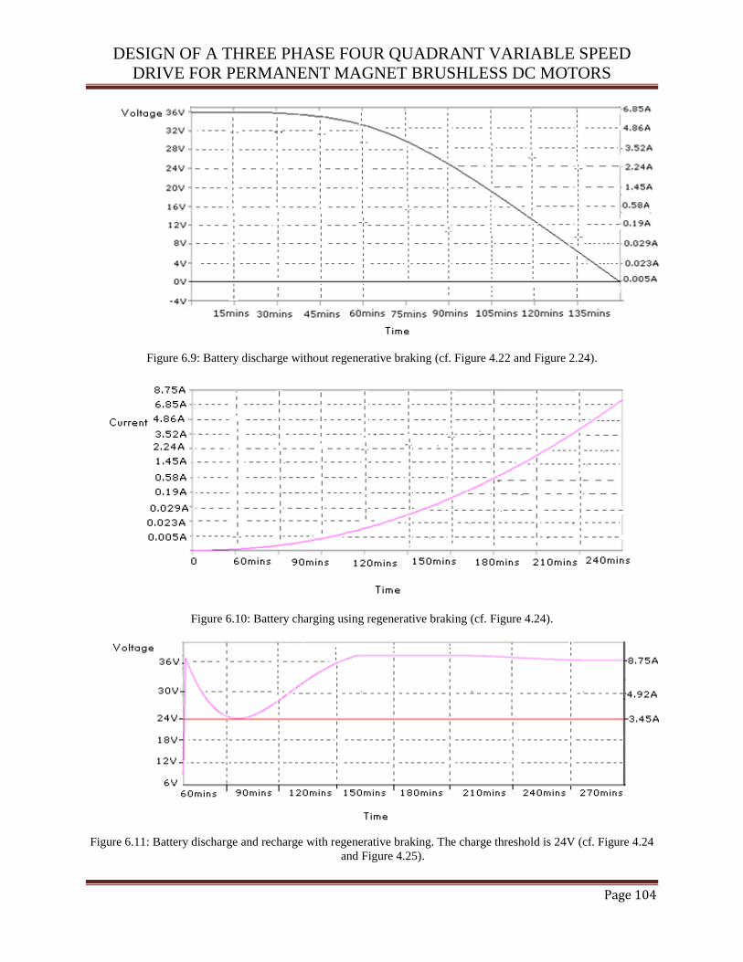
DESIGN OF A THREE PHASE FOUR QUADRANT VARIABLE SPEED
DRIVE FOR PERMANENT MAGNET BRUSHLESS DC MOTORS
Page 104
Figure 6.9: Battery discharge without regenerative braking (cf. Figure 4.22 and Figure 2.24).
Figure 6.10: Battery charging using regenerative braking (cf. Figure 4.24).
Figure 6.11: Battery discharge and recharge with regenerative braking. The charge threshold is 24V (cf. Figure 4.24
and Figure 4.25).

DESIGN OF A THREE PHASE FOUR QUADRANT VARIABLE SPEED
DRIVE FOR PERMANENT MAGNET BRUSHLESS DC MOTORS
Page 105
Figure 6.12: Battery voltage which is limited at 36V (cf. Figure 4.22 and Figure 4.24).
Figure 6.13: Torque versus current characteristic (cf. Figure 4.17).

DESIGN OF A THREE PHASE FOUR QUADRANT VARIABLE SPEED
DRIVE FOR PERMANENT MAGNET BRUSHLESS DC MOTORS
Page 106
Figure 6.14: Speed versus voltage characteristic (cf. Figure 4.21).
Figure 6.15: Torque versus Speed characteristic (cf. Figure 4.17 and Figure 21).

DESIGN OF A THREE PHASE FOUR QUADRANT VARIABLE SPEED
DRIVE FOR PERMANENT MAGNET BRUSHLESS DC MOTORS
Page 107
6.3 ANALYSIS OF RESULTS AND DISCUSSION
LTSpice was used for the simulations described in this study. As shown in Figure 6.2 and Figure
6.3, at no time were both the high and low sides MOSFETS switched on at the same time.
Reversing the mechanical pedal overrides the position of the throttle and changes the drive to the
regenerative braking mode.
Motor speed was monitored by the microcontroller to ensure that the reversing switch is only
activated when the PWM signal is off and the motor has stopped. The throttle has to be turned
down to zero before the direction can be changed from the forward to the reverse direction and
vice versa. Figure 6.2 and Figure 6.5b show the bus voltage and motor current of the PMBLDC
motor when a phase change occurs. Figure 6.5a shows the motor current when there is no load on
the motor. The motor current decreases when the current from the previously conducting phase
freewheels within the phase switcher (cf Figure. 4.8) through the unchanged phase when the next
phase is switched on. Figure 6.4a and Figure 6.4b indicate the simulated and measured high side
PWM output for each phase which is within the required switching voltage.
The dead-time in the current-mode was difficult to control due to a fast time delay needed to
shut down the PWM signal when the motor current exceeded its parameter. The result in Figure
6.6 shows a gradual decay in the current over time. This current decrease indicates a loading
effect on the battery. Over time, this load on the battery will cause the speed to gradually
decrease. Judging from the rate of change in Figure 6.6, it would take approximately 10μs for the
controller to switch the PWM off in the event of an over-speed condition. Figure 6.8 indicates
the bus voltage and the motor phase current when operated with a fixed average voltage
produced by the PWM having a constant duty cycle. The current reduces to zero at every
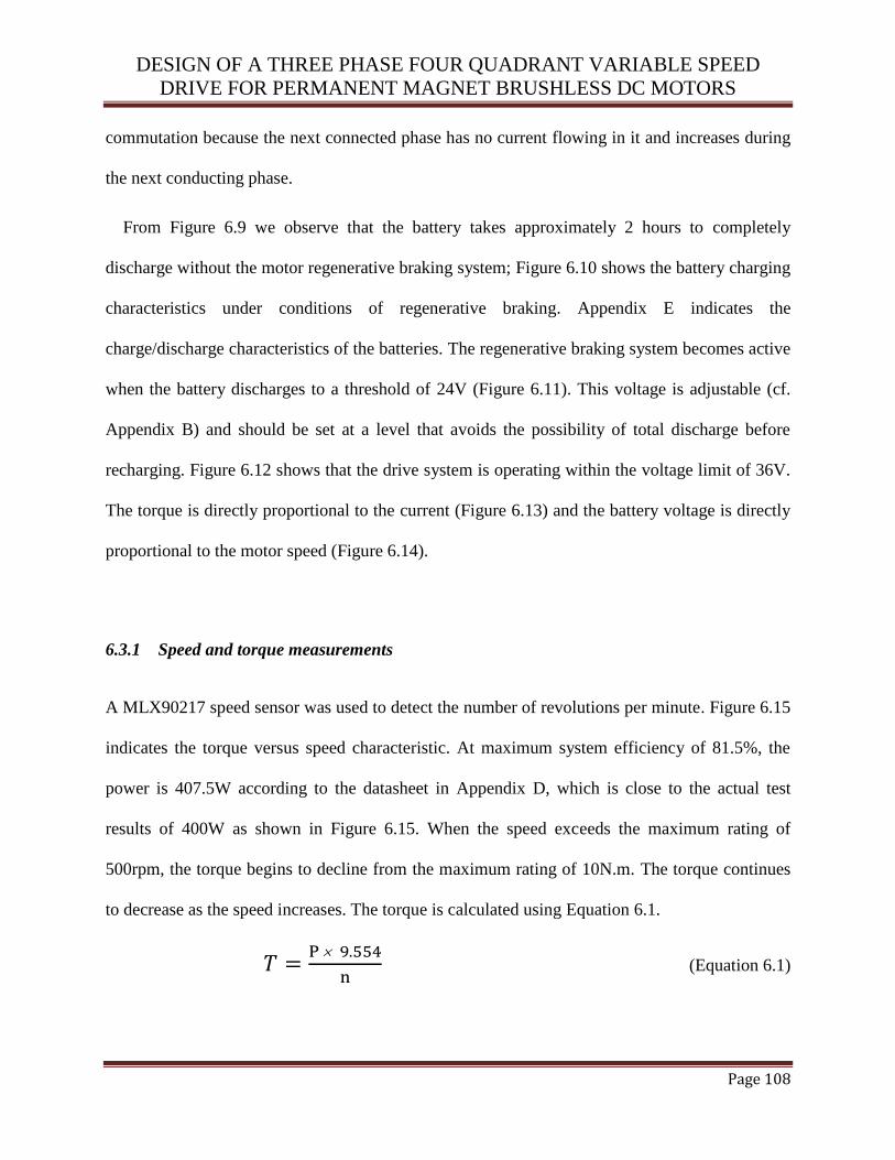
DESIGN OF A THREE PHASE FOUR QUADRANT VARIABLE SPEED
DRIVE FOR PERMANENT MAGNET BRUSHLESS DC MOTORS
Page 108
commutation because the next connected phase has no current flowing in it and increases during
the next conducting phase.
From Figure 6.9 we observe that the battery takes approximately 2 hours to completely
discharge without the motor regenerative braking system; Figure 6.10 shows the battery charging
characteristics under conditions of regenerative braking. Appendix E indicates the
charge/discharge characteristics of the batteries. The regenerative braking system becomes active
when the battery discharges to a threshold of 24V (Figure 6.11). This voltage is adjustable (cf.
Appendix B) and should be set at a level that avoids the possibility of total discharge before
recharging. Figure 6.12 shows that the drive system is operating within the voltage limit of 36V.
The torque is directly proportional to the current (Figure 6.13) and the battery voltage is directly
proportional to the motor speed (Figure 6.14).
6.3.1 Speed and torque measurements
A MLX90217 speed sensor was used to detect the number of revolutions per minute. Figure 6.15
indicates the torque versus speed characteristic. At maximum system efficiency of 81.5%, the
power is 407.5W according to the datasheet in Appendix D, which is close to the actual test
results of 400W as shown in Figure 6.15. When the speed exceeds the maximum rating of
500rpm, the torque begins to decline from the maximum rating of 10N.m. The torque continues
to decrease as the speed increases. The torque is calculated using Equation 6.1.
(Equation 6.1)
DESIGN OF A THREE PHASE FOUR QUADRANT VARIABLE SPEED
DRIVE FOR PERMANENT MAGNET BRUSHLESS DC MOTORS
Page 109
With regards to equation 6.1, T is the torque, P is the power, n is the speed and 9.554 is the
torque constant. The speed of the motor was varied to get a torque measurement. Varying the
speed involved adjusting the motor current. The method used to calculate the torque transferred
involved the maximum torque rating of the motor with the torque to current ratio. From this we
found that our BLDC motor used a current of 2.5A to yield a torque of 1.72Nm. A load was
then applied to detect the effect of the torque. The torque was varied by adjusting the positive
and negative maximum current in the PMBLDC motor which covers the active braking zones,
and also the crossing from motoring into generating zones, which is not possible in the two
quadrant operation (cf. 3.3.2). In this test the voltage was varied up to the maximum of ±36V in
which the motor current is around ±15A (cf. Figure 6.5a and Figure 6.6) and ±20A in the
simulation (cf. Figure 5.1 and Figure 5.3). In the tolerance band scheme, the instantaneous
current is not always exactly equal to the average current. The spikes in Figure 6.4b and Figure
6.7 are caused by commutation events and switching of the current comparators.
6.3.2 Current commutation
The current commutation was analyzed to determine the best method for measuring the effective
BLDC motor current. The current flow between the BLDC motor and the regenerative braking
system uses the open loop voltage control to set the duty cycle, and hence the average value of
the BLDC bus voltage as indicated in Figure 5.2. The current is directly proportional to the
output torque of the motor as shown in Figure 6.13.
The results in Figure 5.3 illustrate the tolerance band current control of the motor at a constant
phase current. Figure 5.1 indicates a modulated DC bus voltage in which the current flowing in

DESIGN OF A THREE PHASE FOUR QUADRANT VARIABLE SPEED
DRIVE FOR PERMANENT MAGNET BRUSHLESS DC MOTORS
Page 110
the motor phase decreases and then slowly rebuilds after each step commutation. The current
reduces to zero at every commutation because the next connected phase has no current flowing
in it. The controller compensates for this, creating a long positive voltage pulse at each
commutation which causes a quick buildup of current during the next conducting phase. The
open loop voltage control forces the duty cycle to be constant, causing the average value of
motor voltage to be smaller than the battery voltage. In the tolerance band scheme, the controller
increased the motor voltage to be equal to the battery voltage for a quick commutation (cf.
Figure 6.2). The torque ripple of the tolerance band method is half that of open loop voltage
control at half the rated speed (cf. Figure 3.24). The current control has the advantage of
producing smoother torque since the current is directly proportional to the torque. This makes the
control system to achieve smooth torque control (cf. section 3.2.3, section 4.2 and section 4.9).
The design of the current controller uses a single current sensor, positioned after the three
phase full bridge or the phase switcher, to senses the effective motor current. The control logic
includes a separate single channel half bridge current controller and phase switcher logic. All the
three phases are involved in each commutation event. This includes the stable phase which
maintains its state during and after commutation, the previous phase which is disconnected after
commutation and the next phase which is energized for the next commutation. The current
commutation from the previous phase to the next phase takes place in the following three steps:
Step 1: The previous and stable phases conduct the motor current.
Step 2: The current builds up in the next phase whilst decaying in the previous phase.
Step 3: The previous phase current decays to zero and the operation continues.

DESIGN OF A THREE PHASE FOUR QUADRANT VARIABLE SPEED
DRIVE FOR PERMANENT MAGNET BRUSHLESS DC MOTORS
Page 111
The current sense resistor signal is being limited to the tolerance band except at commutation
events. The phase switcher MOSFET capacitances charge and discharge through the current
sense resistor as the motor voltage changes between battery and ground. This causes spikes in the
current signal at each transition of the BLDC motor voltage as illustrated in Figure 6.7.
6.3.3 PWM and frequency control
Figure 5.3 shows the phase current and the BLDC motor voltage controlled with a fixed average
voltage produced by PWM of the motor voltage with a constant duty cycle ratio. The current
takes the motor phase resistance and inductance time constants to settle after a commutation
event. This makes the current ripple magnitude large. The phase current and motor voltages were
simulated for motoring operation with a tolerance band current controller. When a commutation
event occurs, the current controller forces the motor back EMF to battery voltage so that the
phase current builds up quickly in the next active phase.
The switching frequency was set to 10 kHz. But the actual system operates with a maximum
switching frequency of 25 kHz (cf. Figure 5.2) due to increases in the battery voltage and the
maximum frequency when the battery pack is accepting a charge. There is also an increase in the
maximum switching frequency as the motor current decreases because the battery voltage which
is supplied by a series combination of three sealed lead acid batteries is not steady for all current
flow rates. The frequency of operation can be affected by the EMF of the unused phase. The
phase inductance of the unused phase experiences a voltage which is equal to its instantaneous
back EMF when the motor voltage is forced to ground. This causes current to build up in this
phase until the BLDC motor voltage is forced to the battery voltage again. The current in the
DESIGN OF A THREE PHASE FOUR QUADRANT VARIABLE SPEED
DRIVE FOR PERMANENT MAGNET BRUSHLESS DC MOTORS
Page 112
unused phase freewheels in the phase switcher through the diodes (cf Figure 4.3). As the rotor of
the motor rotates, the phase voltage of the unused phase passes through zero causing the
switching frequency to be low (cf section 3.2.1).
6.3.4 Motoring mode
The controller is capable of four quadrant operation as discussed in the hardware design (cf.
section 4.2). A BLDC motor current of 15A was instantaneously achieved during the test where
the system was accelerated from rest to the maximum no load speed as shown in Figure 6.5b and
Figure 6.7. The maximum continuous output power from the tests was 400W as illustrated in
Figure 6.15 and 470W in the simulation (cf. Figure 5.5).
The current becomes zero when the current from the previously conducting phase freewheels
within the phase switcher through the unchanged phase when the open circuit phase is switched
on. The current controller forces the motor voltage to the battery to compensate for this loss of
current which is restored in the new phase. At higher currents, the commutation of currents from
one phase to the next takes longer. The controller increases the duty cycle of the BLDC motor
current to compensate for a commutation and the sensed current restarts from zero at each
commutation.
6.3.5 Generating mode
The BLDC motor enters the generating mode when the throttle experiences a negative BLDC
motor current. The BLDC motor must be rotating to convert mechanical energy to electrical
energy. The battery affected the limits of both the motoring and generating tests by having a

DESIGN OF A THREE PHASE FOUR QUADRANT VARIABLE SPEED
DRIVE FOR PERMANENT MAGNET BRUSHLESS DC MOTORS
Page 113
terminal voltage that varied approximately linearly with the current which drained the battery
rapidly as shown in Figure 6.8. The maximum power delivered to the battery during the test was
36V x 8.75A = 315W as illustrated in Figure 6.11.
Commutation does not affect the negative current regulation since the body diodes of the
MOSFETs in Figure 4.3 always provide a path through the sense resistor. The mechanical torque
on the BLDC motor is smoother when generating power, provided the commutation induced
phase shift of the phase currents is small. The current spikes from the MOSFET output
capacitance are higher when the motor voltage is changing from the battery to ground as shown
in the results in Figure 6.7. When the current decays to zero in the unused phase, the phase to
phase voltage returns to its open circuit value.
6.3.6 Forward/Reverse control
The reverse control requires a positive voltage and negative current or negative voltage and
current. This cannot be achieved using two quadrant control (cf. section 3.3.2). The motor has to
completely stop before the direction can be changed from forward to reverse direction. The
throttle has to be turned down to zero before the reverse switch can be activated. For automatic
direction switching, the throttle input was set at an average BLDC motor current. The speed of
the motor was then varied from positive to negative to cause the direction to change from
forward to reverse. The direction changed from reverse to forward when the motor speed is
varied from negative to positive. The direction of the VSD can be interpreted as forward when
the lower comparator of the current controller (cf. Figure 4.17) is high or when the input is above
the reference voltage. The comparator changes states when the input voltage is exceeded by the
current sensor voltage, therefore putting the controller in reverse direction. A change of the
DESIGN OF A THREE PHASE FOUR QUADRANT VARIABLE SPEED
DRIVE FOR PERMANENT MAGNET BRUSHLESS DC MOTORS
Page 114
controller direction bit is needed when the value of BLDC motor voltage and the back EMF
changes polarity.
6.3.7 Limitation and protection
The controller was loaded with a set of operating parameters to test the speed, voltage and
current limiting. The battery voltage was varied to give an under-voltage and an over-voltage
condition in which the power stage was automatically shut down to indicate a faulty condition.
The speed was varied to an over speed condition in which the PWM output was disabled until
the motor speed was reduced below the speed limit. The battery voltage was limited at 36V as
shown in Figure 6.12. The current was limited in all quadrants of operation.
6.4 SUMMARY AND CONCLUSIONS
The test was done at different speed levels to obtain a safe operating area for the controller. A
step input was applied to the current sense input to indicate an over-current condition. The
oscilloscope was set to be triggered by the step input. The DC bus voltage does not change
during the set period if the drive operates within its limit. The battery terminal voltage varies
with the speed to its maximum value as displayed on the multimeter. The test proved that the
controller operated as desired and provided a control system that implements all the required
features within adequate response times.
DESIGN OF A THREE PHASE FOUR QUADRANT VARIABLE SPEED
DRIVE FOR PERMANENT MAGNET BRUSHLESS DC MOTORS
Page 115
This page is intentionally blank
DESIGN OF A THREE PHASE FOUR QUADRANT VARIABLE SPEED
DRIVE FOR PERMANENT MAGNET BRUSHLESS DC MOTORS
Page 116
CHAPTER 7
SUMMARY OF STUDY, CONCLUSIONS
AND RECOMMENDATIONS
This chapter provides conclusions on the overall design covered in this research study.
7.1 SUMMARY AND CONCLUSIONS
The overall result of this study is the design of a simple VSD based on digital logic. Testing of
the controller and its associated circuitry has proven that the system can operate safely in all four
quadrants. Torque controlled operation was achieved by controlling the path and the magnitude
of the current in the BLDC motor. The throttle is used to control the current and therefore the
torque within the operating limits of the VSD. The features provided by the VSD system are well
suited to an E-bike application. The fully variable parameters of the controller allows for the safe
operation of the E-bike during forward and reverse motoring, as well as regenerative braking.
The analog comparators used in the current control system provided accurate thresholds and
digital output which makes the current amplification easier. The arrangement of power switches
affects the commutation process. The relationship between the measured current in the BLDC
motor and the torque is dependent on the speed of commutation. A faster transfer of current
between the commutating phases keeps the relationship between the motor current and torque
more stable. This can be analysed in the generating or regenerating mode of operation. The

DESIGN OF A THREE PHASE FOUR QUADRANT VARIABLE SPEED
DRIVE FOR PERMANENT MAGNET BRUSHLESS DC MOTORS
Page 117
separation of the phase switcher and current controller resulted in a simple current measurement
system. The different modules were designed and tested in isolation before assembling the whole
system. This approach provided fast detection of faults and quick replacement of faulty
components.
Lossless current sensing scheme is required since the sense resistor dissipates power and
therefore reduces efficiency. A lossless scheme can also reduce the parasitic inductance
introduced into the high power loop to reduce the transient voltages and filtering requirements.
The effect of routing the Hall sensor wires away from the phase wires within the motor could not
be achieved since all the wires shared the same insulation. Therefore coupling between the Hall
sensor signals and the high power signals could not be avoided. This caused a great interference
between the signals which affected the position sensors. The VSD operating frequency varied as
the rotor position and load changed which decreased the radio interference produced by
switching the high power MOSFETs.
The literature review compared other storage methods with their advantages and
disadvantages. It revealed that the best solution to the energy storage system would be a
combination of technologies, such as an ultra capacitor for high intermittent power and a
separate battery for low power high energy density storage as proposed by (Yan and Patterson,
2001) in their novel power management scheme. These types of solutions have the potential to
perform much better.
The three phase inverter bridge (cf. Figure 4.8) caused the inactive phase of the three phase
brushless DC motor to stop conducting as quickly as possible after each commutation event. The
DESIGN OF A THREE PHASE FOUR QUADRANT VARIABLE SPEED
DRIVE FOR PERMANENT MAGNET BRUSHLESS DC MOTORS
Page 118
inverter bridge increased the resolution of the position sensor and changed the switching pattern
that forces the motor voltage to ground. The switching pattern ensures that the inactive phase
does not conduct by turning on an appropriate pair of top or bottom side switches that will force
the BLDC motor voltage to ground. For the three phase motor, the side used to force the BLDC
motor voltage to ground would change at 600 intervals but at a point exactly 30
0 after each
commutation. This represents one of the bus clamped space vector pulse width modulation
switching schemes implemented by (Narayanan et al., 2006).
All objectives of this project were successfully achieved. The entire control system was
designed, constructed and tested together with its associated elements. These include the phase
switcher, gate drive circuits, current controller circuits, temperature control circuits, power
supplies, protection logic and the associated software for the microcontroller. The control system
successfully implements the entire features of four quadrant operation. Most VSD systems for
electric bicycles are designed to operate in only two quadrants which do not allow reverse
operation and also offer poor regenerative braking. Regenerative braking can fully be achieved in
four quadrant operation.
The completion of this project has demonstrated the feasibility of using a highly integrated
approach to the circuit design. It has also highlighted the benefits of using software to implement
many useful features in the design, with minimal cost.

DESIGN OF A THREE PHASE FOUR QUADRANT VARIABLE SPEED
DRIVE FOR PERMANENT MAGNET BRUSHLESS DC MOTORS
Page 119
7.2 RECOMMENDATIONS
Recommendations to improve the design include the following:
1. Batteries: An E-bike or EV motor control can be powered with high technology batteries
such as lithium cells or hydrogen fuel cells to make a long distance vehicle. It can also be
incorporated with an internal combustion engine to form a hybrid drive train.
2. Storage Elements: Use ultra capacitors to improve the energy storage scheme. Ultra
capacitors combined with the battery have the potential to improve the performance of
the energy storage system for long distance riding. They have the ability to accept and
deliver energy quickly and efficiently during acceleration and deceleration.
3. High Torque Motors: Use a higher torque motor when carrying out a road test. Appendix
F shows a complete system mounted on the bicycle and ready for road testing; Appendix
G compares the different BLDC motor models and their respective manufacturers. A load
cell can be installed to measure the torque output of the PMBLDC motor. This would
enable the observation of torque ripple from the PMBLDC motor and the controller with
the parasitic torque from the friction in the system. Install a speed detection sensor on the
motor to detect the speed to avoid over-speed. Also implement the four quadrant design
for operation in all quadrants to allow reverse and regenerative braking. This allows the
controller to be used in electric vehicle systems.
4. Power Supply: Design a complete power supply for the different circuits as they all
require different voltage levels for activation. Reduce coupling between the Hall sensor

DESIGN OF A THREE PHASE FOUR QUADRANT VARIABLE SPEED
DRIVE FOR PERMANENT MAGNET BRUSHLESS DC MOTORS
Page 120
signals and the high power signals. Hall sensor wires should be wrapped separately from
the phase wires to avoid signal interference.

DESIGN OF A THREE PHASE FOUR QUADRANT VARIABLE SPEED
DRIVE FOR PERMANENT MAGNET BRUSHLESS DC MOTORS
Page 121
REFERENCES
1. K. Taehyung, L. Hyung-Woo, P. Leila and E. Mehrdad. “Optimal Power and Torque
Control of a Brushless DC (BLDC) Motor/Generator Drive in Electric and Hybrid
Electric Vehicles.” Energy Conversion and Management, vol.56, pp.1280-1281,
Elsevier, India, 2006.
2. D. Thompson. “Brushless DC Motor Control Made Easy.” Internet:
www.microchip.com/downloads/en/AppNotes/00857a.pdf, Jun. 18, 2008 [Apr. 20,
2012].
3. A. George and T. William. “Performance evaluation of a permanent magnet brushless
DC linear drive for high-speed machining using finite element analysis.” Finite
Elements in Analysis and Design, vol.35, pp. 175-178, 2000.
4. Y. Komatsu, A. Tur-Amgalan, A. Yoshihiko, Z. Syed Abdul Kadir and T. Keita.
“Design of the Unidirectional Current Type Coreless DC Brushless Motor for Electrical
Vehicle with Low Cost and High Efficiency,” IEEE/SPEEDAM, 2010, pp.1038-1039.
5. P. Boonyanant, R. Chaisricharoenb and Janpana. “Control of the Brushless DC Motor
in Combine Mode.” Procedia Engineering, vol.32, pp.282-283, 2012.
6. D. Collins. “DOE FE Distributed Generation (DG) Fuel Cells Program,” IEEE Applied
Power Electronics Conference, 2005, pp.832-834.
7. B. Singh and S. Singh. “State of the art on permanent magnet brushless DC motor
drivers.” Journal of Power Electronics, vol.56, pp.9-11, 2009.
8. J. Figueroa, C. Brocart, J. Cros and P. Viarouge. “Simplified simulation methods for
polyphase brushless DC motors”, Mathematics and Computers in Simulation, vol.63,
pp.222-224, 2003.
9. J. Faiz, M.R. Azizian and M. Aboulghasemian-Azami. “Simulation and analysis of
brushless DC motor drives using hysteresis, ramp comparison and predictive current
control techniques,” Dec. 1994, pp. 351-353.
DESIGN OF A THREE PHASE FOUR QUADRANT VARIABLE SPEED
DRIVE FOR PERMANENT MAGNET BRUSHLESS DC MOTORS
Page 122
10. M.D. Britten, I.D. de Vries and J. Tapson. “Discrete Logic Permanent Magnet
Brushless DC Motor Controller,” in Proceedings of the 16th Southern African
Universities Power Engineering Conference, January 2007, pp. 132 –134.
11. Toyota Motor Corporation. “Solar car motor and drivetrain.” Internet: www.speedace.info, Aug. 13, 2006 [May 11, 2012].
12. Safidrive Technology. “Technical information on motors and drives.” Internet:
www.sdt-safidrivetechnology.co.uk, Sept. 12, 2009 [May 22, 2012].
13. D. Patterson and R. Spee. “The Design and Development of an Axial Flux Permanent
Magnet Brushless DC Motor for Wheel Drive in a Solar Powered Vehicle.” IEEE
Transactions on Industry Applications, vol. 31, pp. 1054 – 1061, Sep. 1995.
14. Y. Padmaraja, Microchip Technology. “Brushless DC (BLDC) Motor Fundamentals.”
Internet: www.microchip.com, Feb. 2003[April 12, 2014].
15. H. Wang. “Design and Implementation of Brushless DC Motor Drive and Control
System,” International Workshop on Information and Electronics Engineering
(IWIEE), 2012, pp.2220–2223.
16. A. Kasei Microdevices. “Detection of Brushless Motor Rotation.” Internet:
www.akm.com/akm/en/product/add/magnetic sensors/0027/, Jan. 2011 [Jun. 20,
2014].
17. C.C. Hwang and J.J.Chang. “Design and analysis of a high power density and high
efficiency Permanent Magnet DC Motor.” Journal of Magnetism and Magnetic
Materials, vol. 209, pp.233–238, 2000.
18. Fadal Machine Center. “History about AC and DC Servos for Fadal Machines.”
Internet: www.fadalvmcparts.com, Jun. 2008 [Jun. 20, 2014].
19. EV-INFO. “Electric Bicycle Manufacturers and Models.” Internet: www.ev-
info.com/electric-bicycle manufacturer/, Nov. 2014 [Jul. 15, 2014].
20. S.T. Microelctronics. “Sensorless BLDC Motor Control and BEMF Sampling
Methods with ST7MC,” AN1946 Application Note, 2007, Rev.2, pp. 3–5.
21. Freescale Semiconductor. “3-Phase BLDC Motor Control with Quadrature Encoder
using 56F800/E,” AN1961 Application Note, 2005, Rev.0, pp. 4–8.
DESIGN OF A THREE PHASE FOUR QUADRANT VARIABLE SPEED
DRIVE FOR PERMANENT MAGNET BRUSHLESS DC MOTORS
Page 123
22. B. K. Lee and M. Ehsani. “Advanced BLDC motor drive for low cost and high
performance propulsion system in electric and hybrid vehicles,” IEEE electric
machines and drives conference, 2001, pp.246-251.
23. MSK Corp. “30Amp, 75V 3-Phase MOSFET Brushless Motor Controller.” Internet:
www.DatasheetCatalog.com, Apr. 15, 2011 [Jun. 20, 2013].
24. G. Pavel. “BLDC Motor Control using 8-bit MCU.” Internet:
www.freescale.com/beyondbits, Aug. 8, 2005 [Jul. 10, 2013].
25. T. Heman and T. Rajesh. “Speed Control of Brushless DC Motor Drive Employing
Hard Chopping PWM Technique Using DSP,” Proceedings of India International
Conference on Power Electronics, 2006, pp. 368-375.
26. A. Tashakori and M. Ektsesabi. “Comparison of Different PWM Switching Modes of
BLDC Motor as Drive Train of Electric Vehicles.” World Academy of Science,
Engineering and Technology, vol.63, pp. 719-722, 2012.
27. T. Ishikawa and G. R. Slemon. “A Method of Reducing Ripple Torque in Permanent
Magnet Motors without Skewing.” IEEE Transactions on Magnetics, vol. 29, pp.
2027–2030, Mar.1993.
28. C. Zhao and Y. Wu. “The Design of Brushless DC Motor Controller,” in IEEE
International Conference on Intelligent Control and Information Processing, Aug.
2010, pp.729-731.
29. N. Mohan, W.P. Undel and T.M. Robbins. Power Electronics Converters Application
and Design. USA: John Wiley & Sons Inc, ed., 2003, pp. 461–495.
30. IXYS. “GWM100-01X1 Three phase full bridge.” Internet: www.Alldatasheet.com,
Sep.15, 2009 [Jun. 22, 2013].
31. National Semiconductor. “LM5100A/LM5101A – 3.0 Amp High Voltage High Side
and Low Side Driver.” Internet: www.national.com, Jun. 2007 [May 11, 2013].
32. Texas Instruments. “LM347 JFET-input Quad Operational Amplifiers.” Internet:
www.ti.com, Mar. 2005 [July 11, 2013].
33. ATMEL. “ATmega328 AVR 8-bit Microcontroller.” Internet: www.Alldatasheet.com,
Nov. 2009 [Jun. 7, 2013].
34. G. Narayanan, H.K. Krishnamurthy, D. Zhao and R. Ayyanar. “Advanced Bus-
Clamping PWM Technique Based on Space Vector Approach.” IEEE Transactions on
Power Electronics, vol. 21, No. 4, pp. 974 – 984, Jul. 2006.
DESIGN OF A THREE PHASE FOUR QUADRANT VARIABLE SPEED
DRIVE FOR PERMANENT MAGNET BRUSHLESS DC MOTORS
Page 124
35. A.M. Legowski and Trzynadlowski. “Minimum-Loss Vector PWM Strategy for
Three-Phase Inverters.” IEEE Transactions on Power Electronics, vol. 9, No.1, pp.
26–34, Jan. 1994.
36. S. Kang and S. Sul. “Direct Torque Control of Brushless DC Motor with Nonideal
Trapezoidal Back EMF.” IEEE Transactions on Power Electronics, vol. 10, No.6, pp.
795 –800, Nov. 1995.
37. Y. Zhang, R. Zane, A. Prodic, R. Erickson and D. Maksimovic. “Calibration of
MOSFET On-State Resistance for Precise Current Sensing.” IEEE Power Electronics
Letters, vol. 2, No. 3, pp.100–103, Sep. 2004.
38. J.W. Dixon and I.A. Leal. “Current Control Strategy for Brushless DC Motors Based
on a Common DC Signal.” IEEE Transactions on Power Electronics, vol.17, No.2, pp.
232–240, Mar. 2002.
39. J. Karthikeyan and R. Dhana Sekaran. “Current control of brushless dc motor based on
a common dc signal for space operated vehicles,” Electrical Power and Energy
Systems, Aug. 2011, pp.1722-1723.
40. T. Dake and E. Ozalevli. “A Precision High-Voltage Current Sensing Circuit,” in
IEEE Transaction on Circuits and Systems, Jun. 2008, vol.55, No.5, pp.1197–1202.
41. S.H. Kim and C. Doose. “Temperature Compensation of NdFeB Permanent Magnets,”
in Proceedings of the Particle Accelerator Conference, May 1997, vol. 3, pp. 3227 –
3229.
42. Texas Instruments. “SN74LVC1G58 Configurable Multi-Function Gate.” Internet:
www.ti.com, Feb. 2013 [Jul. 11, 2013].
43. Agilent Technologies. “Application Note 290: Practical Temperature Measurement.”
Internet: www.agilent.com, Mar. 2008 [Jun. 20, 2014].
44. Texas Instruments. “LM2917 Frequency to Voltage Converter.” Internet: www.ti.com,
Apr. 2013 [Jul. 11, 2013].
45. Texas Instruments. “LM2576 – 3A, 60V, High-Efficiency, Step-Down Voltage
Regulator.” Internet: www.ti.com, Apr. 2013 [Sep. 10, 2013].
46. Fairchild Semiconductors. “LM7805 Three-Terminal 1A Positive Voltage
Regular.”Internet: www.fairchildsemi.com, Aug. 2013 [Sept. 10, 2013].
47. T. Daniel and H. Patrick. “Regenerative Braking of BLDC motors,” High-
Performance Microcontroller Division, Microchip Technology, 2012, pp.3-8.
DESIGN OF A THREE PHASE FOUR QUADRANT VARIABLE SPEED
DRIVE FOR PERMANENT MAGNET BRUSHLESS DC MOTORS
Page 125
48. V. Thiyagarajan and V. Sekar. “Controlling of Brushless DC Motors in Electric
Bicycles using Electronic Based Circuit with 8-Bit Microcontroller.” International
Journal of Engineering Sciences and Emerging Technologies, vol.4, pp.29 – 32, Dec.
2012.
49. X. Zeng, J. Li and Y. Ren. “Prediction of various discarded lithium batteries in
China,” in IEEE International Symposium on Sustainable Systems and Technology
(ISSST), 2012, pp.1–4.
50. E. Manoj, I. Dino and A. Roselinas. “Supercapacitor/Battery hybrid Powered Electric
Bicycle via a Smart Boost Convertor.” World Electric Vehicle Journal, vol. 4, pp.280-
284, 2010.
51. B. Andrew, M. Marshall and Z. Hengbing. “Lithium batteries and ultracapacitors
alone and in combination in hybrid vehicles: Fuel economy and battery stress
reduction advantages,” in The 25th World Battery, Hybrid and Fuel Cell Electric
Vehicle Symposium & Exhibition, EVS-25 Shenzhen, China, Nov. 2010, pp.1–8.
52. A.F. Burke and M. Miller. “Performance Characteristics of Lithium-ion Batteries of
Various Chemistries for Plug-in Hybrid Vehicles,” EVS-24, Stavanger, Norway, May
2009, pp. 256-262.
53. A.F. Burke and M. Miller. “Electrochemical Capacitors as Energy Storage in Hybrid-
Electric Vehicles,” EVS-24, Stavanger, Norway, May 2009, pp.438–446.
54. X. Yan and D. Patterson. “Novel power management for high performance and cost
reduction in an electric vehicle.” Renewable Energy, vol.22, pp. 177–183, Oct. 2001.
55. Panasonic. “Valve Regulated Lead Acid Batteries LC-RA1212P.” Internet:
www.panasonic.com, Aug. 2011 [Jul. 15, 2014].
56. Maxwell Technology. “BC Power Series BOOSTCAP Ultracapacitors.” Internet:
www.maxwell.com/esm/, Jun. 2013 [Jul. 15, 2014].
57. Batteryspace. “36V-Nimh-Battery- Pack-Series.” Internet:
www.batteryspace.com/36V-Nimh-Battery-Pack-Series.aspx, Feb.2013 [Jul. 15,
2014].
58. Dixon Batteries. “Li-Polymer Batteries.” Internet: www.dixonbatteries.co.za/leisure-1,
Dec. 2013 [Jul.15, 2014].
59. Ebay. “Hydrogen-Fuel-Cells.” Internet: www.ebay/bhp/hydrogen-fuel-cell, Jan. 2014
[Jul. 15, 2014].
DESIGN OF A THREE PHASE FOUR QUADRANT VARIABLE SPEED
DRIVE FOR PERMANENT MAGNET BRUSHLESS DC MOTORS
Page 126
60. I.D. de Vries and D. B. Jenman. “The Potential of Electric bicycles to provide low cost
Transport, Mobility and Economic Empowerment in South Africa,” in Proceedings of
the 25th
Southern African Transport Conference, 2006, pp.90–96.
61. Z. Salam. “Power Electronics and Drives,” Application note version 3, 2003, pp. 10–
20.
62. Advanced Thermal Solutions. “Heat-Sink Types and how they are made.” Internet:
www.qats.com, Aug. 2013 [Jul. 18, 2014].
63. S. Colton. “3ph Duo: 2 x 1kW Brushless Motor Controller with Field-Oriented
Control,” Design Notes, 2010, Rev.0, pp.23–30.
64. Q. Wu and W. Tian. “Design of Permanent Magnet Brushless DC Motor Control
System Based on dsPIC30F4012,” International Workshop on Information and
Electronics Engineering (IWIEE), 2012, pp.4224–4227.
65. C. Elmas and O. Ustun. “A hybrid controller for the speed control of a permanent
magnet synchronous motor drive.” Elsevier, Control Engineering Practice, vol.16, pp.
260–270, 2008.
66. A. Namboodiri and S.W. Harshal. “Unipolar and Bipolar PWM Inverter.”
International Journal for Innovative Research in Science & Technology, vol. 1, pp.
237-239, 2014.
67. Agilent Technologies. “Application Note 290: Practical Temperature Measurement,”
Internet: http://www.agilent.com, Mar. 2008 [Jun. 20, 2014].

DESIGN OF A THREE PHASE FOUR QUADRANT VARIABLE SPEED
DRIVE FOR PERMANENT MAGNET BRUSHLESS DC MOTORS
Page 127
APPENDIX A
CONTROLLER SCHEMATIC

DESIGN OF A THREE PHASE FOUR QUADRANT VARIABLE SPEED
DRIVE FOR PERMANENT MAGNET BRUSHLESS DC MOTORS
Page 128
APPENDIX B
SOFTWARE CODE
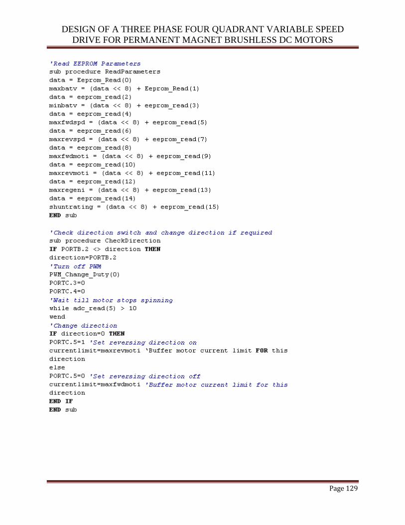
DESIGN OF A THREE PHASE FOUR QUADRANT VARIABLE SPEED
DRIVE FOR PERMANENT MAGNET BRUSHLESS DC MOTORS
Page 129

DESIGN OF A THREE PHASE FOUR QUADRANT VARIABLE SPEED
DRIVE FOR PERMANENT MAGNET BRUSHLESS DC MOTORS
Page 130
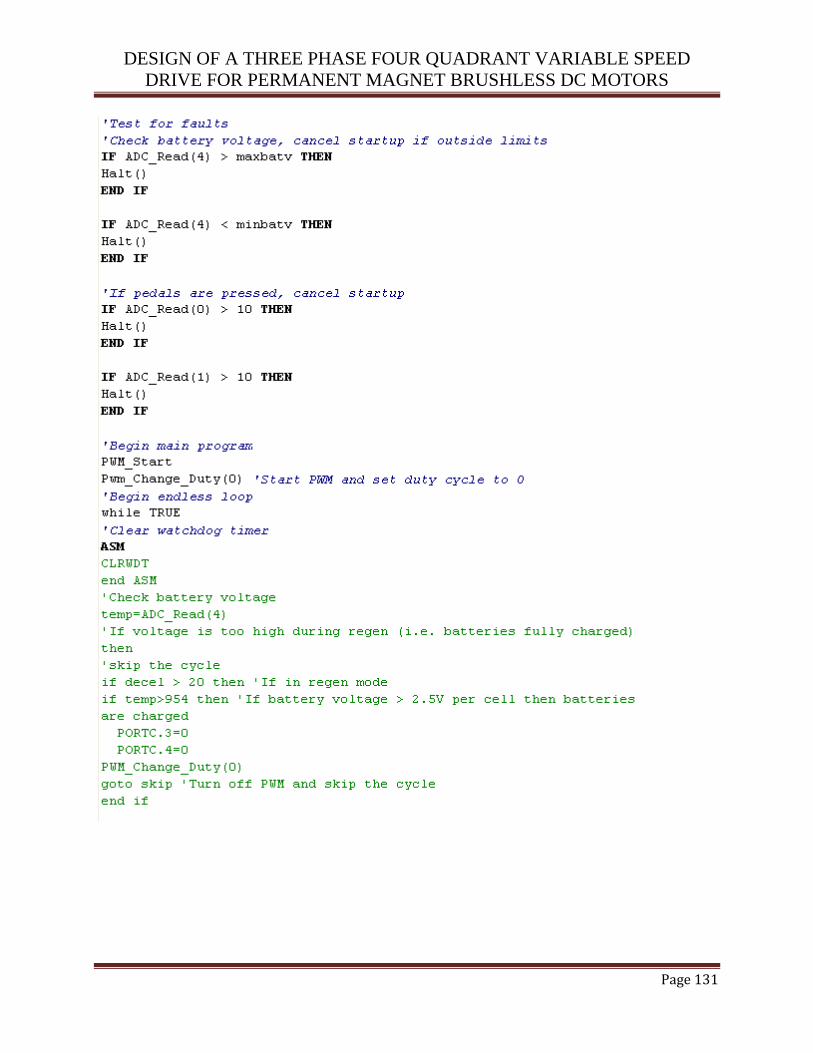
DESIGN OF A THREE PHASE FOUR QUADRANT VARIABLE SPEED
DRIVE FOR PERMANENT MAGNET BRUSHLESS DC MOTORS
Page 131
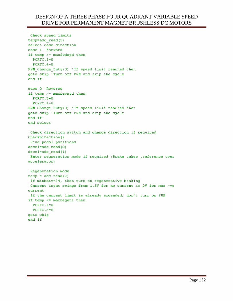
DESIGN OF A THREE PHASE FOUR QUADRANT VARIABLE SPEED
DRIVE FOR PERMANENT MAGNET BRUSHLESS DC MOTORS
Page 132
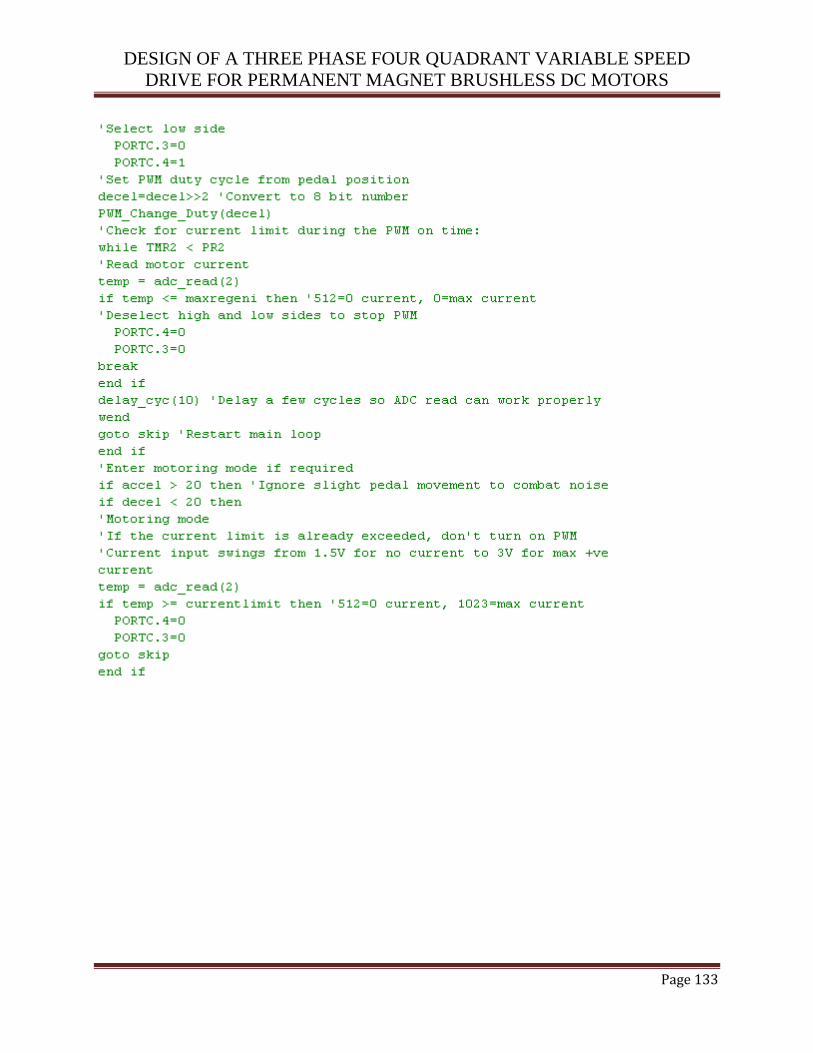
DESIGN OF A THREE PHASE FOUR QUADRANT VARIABLE SPEED
DRIVE FOR PERMANENT MAGNET BRUSHLESS DC MOTORS
Page 133

DESIGN OF A THREE PHASE FOUR QUADRANT VARIABLE SPEED
DRIVE FOR PERMANENT MAGNET BRUSHLESS DC MOTORS
Page 134
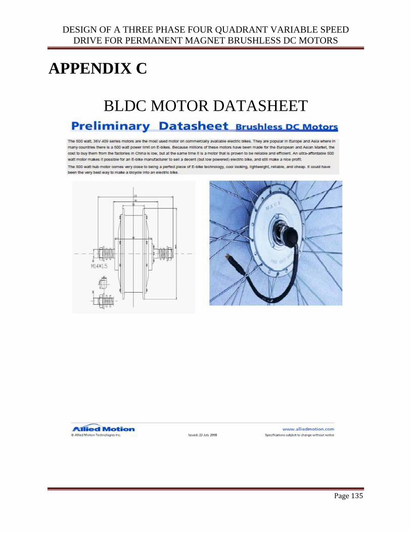
DESIGN OF A THREE PHASE FOUR QUADRANT VARIABLE SPEED
DRIVE FOR PERMANENT MAGNET BRUSHLESS DC MOTORS
Page 135
APPENDIX C
BLDC MOTOR DATASHEET
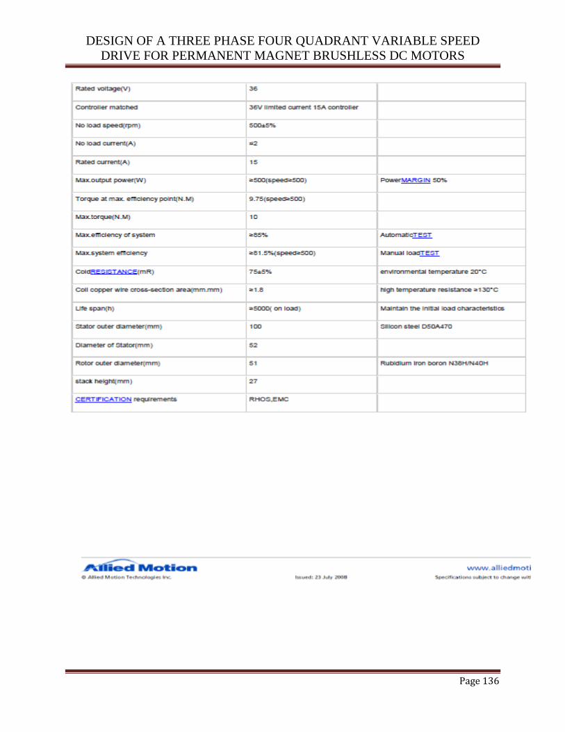
DESIGN OF A THREE PHASE FOUR QUADRANT VARIABLE SPEED
DRIVE FOR PERMANENT MAGNET BRUSHLESS DC MOTORS
Page 136
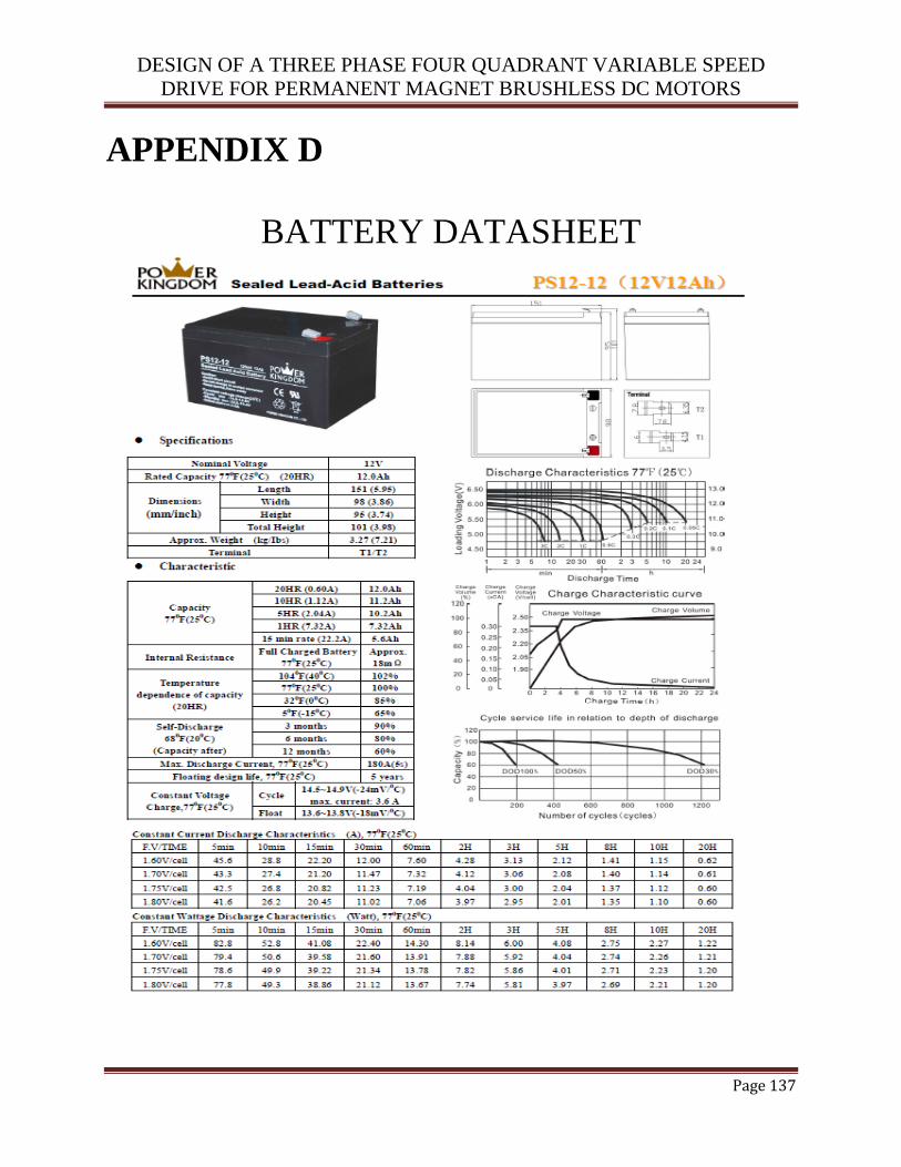
DESIGN OF A THREE PHASE FOUR QUADRANT VARIABLE SPEED
DRIVE FOR PERMANENT MAGNET BRUSHLESS DC MOTORS
Page 137
APPENDIX D
BATTERY DATASHEET
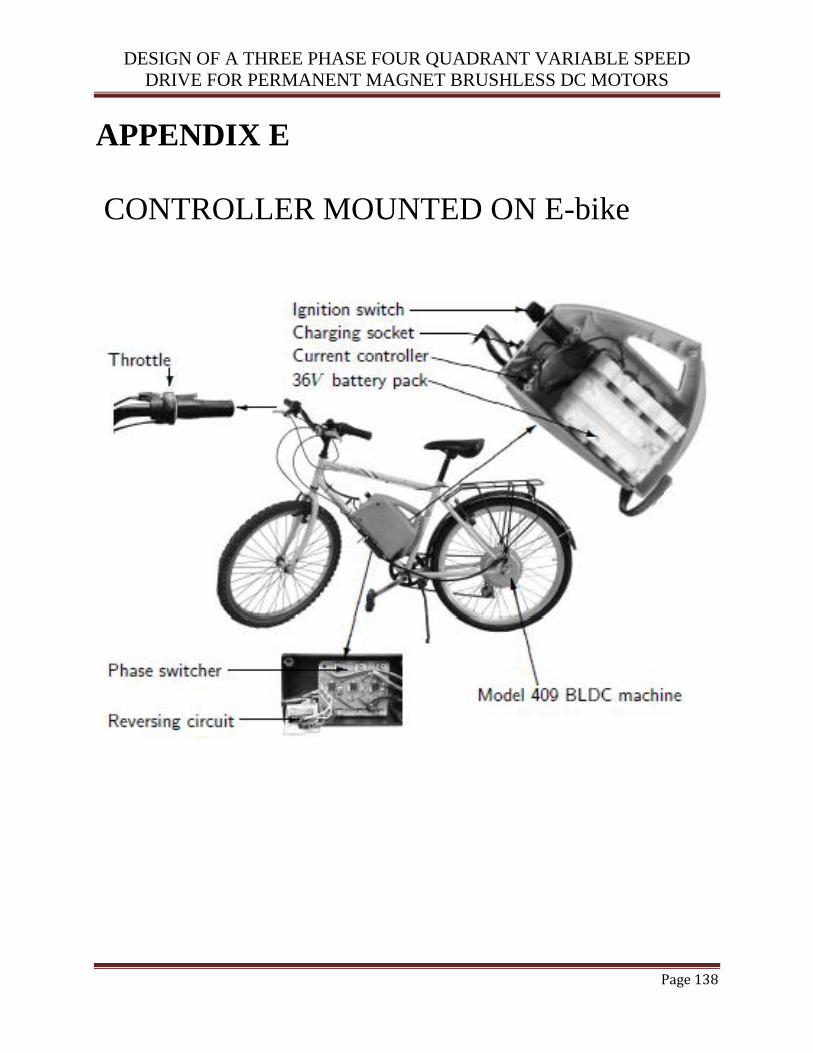
DESIGN OF A THREE PHASE FOUR QUADRANT VARIABLE SPEED
DRIVE FOR PERMANENT MAGNET BRUSHLESS DC MOTORS
Page 138
APPENDIX E
CONTROLLER MOUNTED ON E-bike
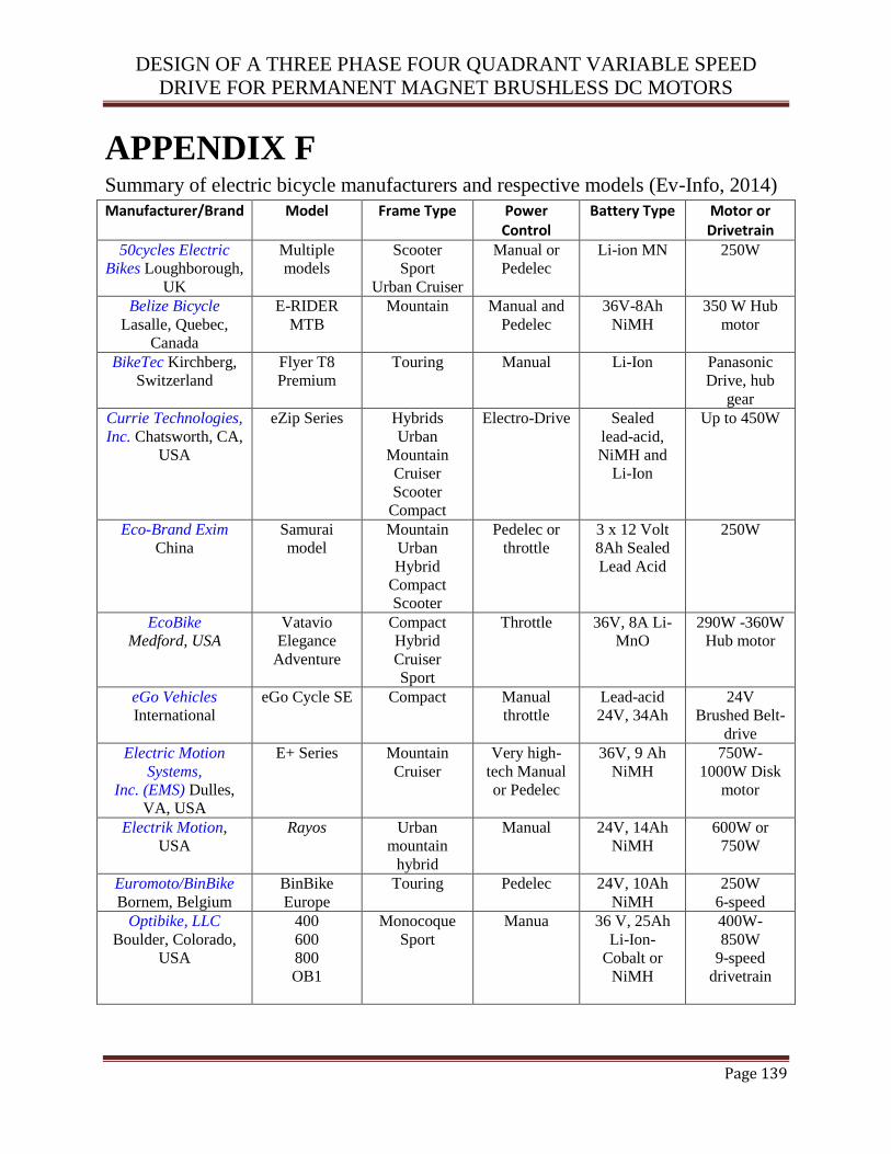
DESIGN OF A THREE PHASE FOUR QUADRANT VARIABLE SPEED
DRIVE FOR PERMANENT MAGNET BRUSHLESS DC MOTORS
Page 139
APPENDIX F Summary of electric bicycle manufacturers and respective models (Ev-Info, 2014)
Manufacturer/Brand Model Frame Type Power Control
Battery Type Motor or Drivetrain
50cycles Electric
Bikes Loughborough,
UK
Multiple
models
Scooter
Sport
Urban Cruiser
Manual or
Pedelec
Li-ion MN 250W
Belize Bicycle
Lasalle, Quebec,
Canada
E-RIDER
MTB
Mountain Manual and
Pedelec
36V-8Ah
NiMH
350 W Hub
motor
BikeTec Kirchberg,
Switzerland
Flyer T8
Premium
Touring Manual Li-Ion Panasonic
Drive, hub
gear
Currie Technologies,
Inc. Chatsworth, CA,
USA
eZip Series Hybrids
Urban
Mountain
Cruiser
Scooter
Compact
Electro-Drive Sealed
lead-acid,
NiMH and
Li-Ion
Up to 450W
Eco-Brand Exim
China
Samurai
model
Mountain
Urban
Hybrid
Compact
Scooter
Pedelec or
throttle
3 x 12 Volt
8Ah Sealed
Lead Acid
250W
EcoBike
Medford, USA
Vatavio
Elegance
Adventure
Compact
Hybrid
Cruiser
Sport
Throttle 36V, 8A Li-
MnO
290W -360W
Hub motor
eGo Vehicles
International
eGo Cycle SE Compact Manual
throttle
Lead-acid
24V, 34Ah
24V
Brushed Belt-
drive
Electric Motion
Systems,
Inc. (EMS) Dulles,
VA, USA
E+ Series Mountain
Cruiser
Very high-
tech Manual
or Pedelec
36V, 9 Ah
NiMH
750W-
1000W Disk
motor
Electrik Motion,
USA
Rayos Urban
mountain
hybrid
Manual 24V, 14Ah
NiMH
600W or
750W
Euromoto/BinBike
Bornem, Belgium
BinBike
Europe
Touring Pedelec 24V, 10Ah
NiMH
250W
6-speed
Optibike, LLC
Boulder, Colorado,
USA
400
600
800
OB1
Monocoque
Sport
Manua 36 V, 25Ah
Li-Ion-
Cobalt or
NiMH
400W-
850W
9-speed
drivetrain