Embed Size (px)
Citation preview
Journal of Network and Computer Applications ] (]]]]) ]]]–]]]
Contents lists available at SciVerse ScienceDirect
Journal of Network and Computer Applications
1084-80
http://d
n Corr
E-m
hyaghm
Rahman
ah.moh
Pleaswire
journal homepage: www.elsevier.com/locate/jnca
HOCA: Healthcare Aware Optimized Congestion Avoidance and controlprotocol for wireless sensor networks
Abbas Ali Rezaee a,n, Mohammad Hossein Yaghmaee b, Amir Masoud Rahmani a,Amir Hossein Mohajerzadeh b
a Department of Computer Engineering, Science and Research Branch, Islamic Azad University, Tehran, Iranb Department of Computer Engineering, Ferdowsi University of Mashhad, Mashhad, Iran
a r t i c l e i n f o
Article history:
Received 11 May 2012
Received in revised form
17 December 2012
Accepted 23 February 2013
Keywords:
Wireless sensor networks
Congestion control
Healthcare
Routing protocol
Optimization
45/$ - see front matter & 2013 Elsevier Ltd. A
x.doi.org/10.1016/j.jnca.2013.02.014
esponding author. Tel.: þ98 9153152739.
ail addresses: [email protected] (A.A. Rez
[email protected] (M.H. Yaghmaee),
[email protected] (A.M. Rahmani),
[email protected] (A.H. Mohajerza
e cite this article as: Rezaee AA, eless sensor networks. Journal of Net
a b s t r a c t
Wireless sensor networks consist of a large number of small, low-power sensors that communicate
through wireless links. Wireless sensor networks for healthcare have emerged in recent years as a
result of the need to collect data about patients’ physical, physiological, and vital signs in the spaces
ranging from personal to hospital and availability of the low cost sensors that enables this data
collection. One of the major challenges in these networks is to mitigate congestion. In healthcare
applications, such as medical emergencies or monitoring vital signs of patients, because of the
importance and criticality of transmitted data, it is essential to avoid congestion as much as possible
(and in cases when congestion avoidance is not possible, to control the congestion). In this paper, a data
centric congestion management protocol using AQM (Active Queue Managements) is proposed for
healthcare applications with respect to the inherent characteristics of these applications. This study
deals with end to end delay, energy consumption, lifetime and fairness. The proposed protocol which is
called HOCA avoids congestion in the first step (routing phase) using multipath and QoS (Quality of
Service) aware routing. And in cases where congestion cannot be avoided, it will be mitigated via an
optimized congestion control algorithm. The efficiency of HOCA was evaluated using the OPNET
simulator. Simulation results indicated that HOCA was able to achieve its goals.
& 2013 Elsevier Ltd. All rights reserved.
1. Introduction
Wireless Sensor Networks (WSNs) have been widely applied indifferent areas such as healthcare monitoring (Akyildiz et al.,2002; Armijo et al., 2007; Cao et al., 2005). They have inherentcharacteristics unlike traditional wireless networks. Sensor nodeshave scarce resources for computation, storage, communicationbandwidth, and, most importantly, energy supply. So far, exten-sive studies have been done on different layers of WSNs (Akkayaand Younis, 2005; Sohraby and Wang, 2006). The event-drivennature of WSNs leads to unpredictable network load, especially inhealthcare applications. Typically, WSNs carry low traffic loadwhen there are no special events. But the occurrence of importantevents may cause burst traffics which lead to congestion in thenetwork. Transport protocols control congestion in end to end orcross layer manner.
ll rights reserved.
aee),
deh).
t al. HOCA: Healthcare Awwork and Computer Applic
Nowadays, Healthcare aware Wireless Sensor Networks(HWSNs) have received a great attention due to the propertiesof WSNs such as reliability, interoperability, efficiency, wearabil-ity, low-power consumption and inexpensiveness. One of theapplications of WSNs is remote monitoring of patients by doctorsand nurses which eliminates the need to be physically present inthe patient sites (Cao et al., 2006). Figure 1 shows differentsensors attached to patients being capable of sensing patientinformation which can be sensitive (vital signs, such as the heartrate and breathing condition) or non-sensitive (motional signs,such as legs sensors). The received information can be trans-mitted to the control center with the help of neighboring nodes.Sensitive information needs low delay and low packet loss whilenon-sensitive data can tolerate more delay and more packet loss.We restricted ourselves to healthcare applications which requirestationary sensor nodes (they do not change their locations for atleast a few hours).
In medical emergencies, it is quite likely that the sensorsplaced in the different patients sense and transmit vital patientinformation very frequently and simultaneously. This leads toincreased likelihood of network congestion in such applications.Congestion in WSNs leads to dropping of packets at the nodes,increased consumption of the limited energy in the nodes and
are Optimized Congestion Avoidance and control protocol forations (2013), http://dx.doi.org/10.1016/j.jnca.2013.02.014i
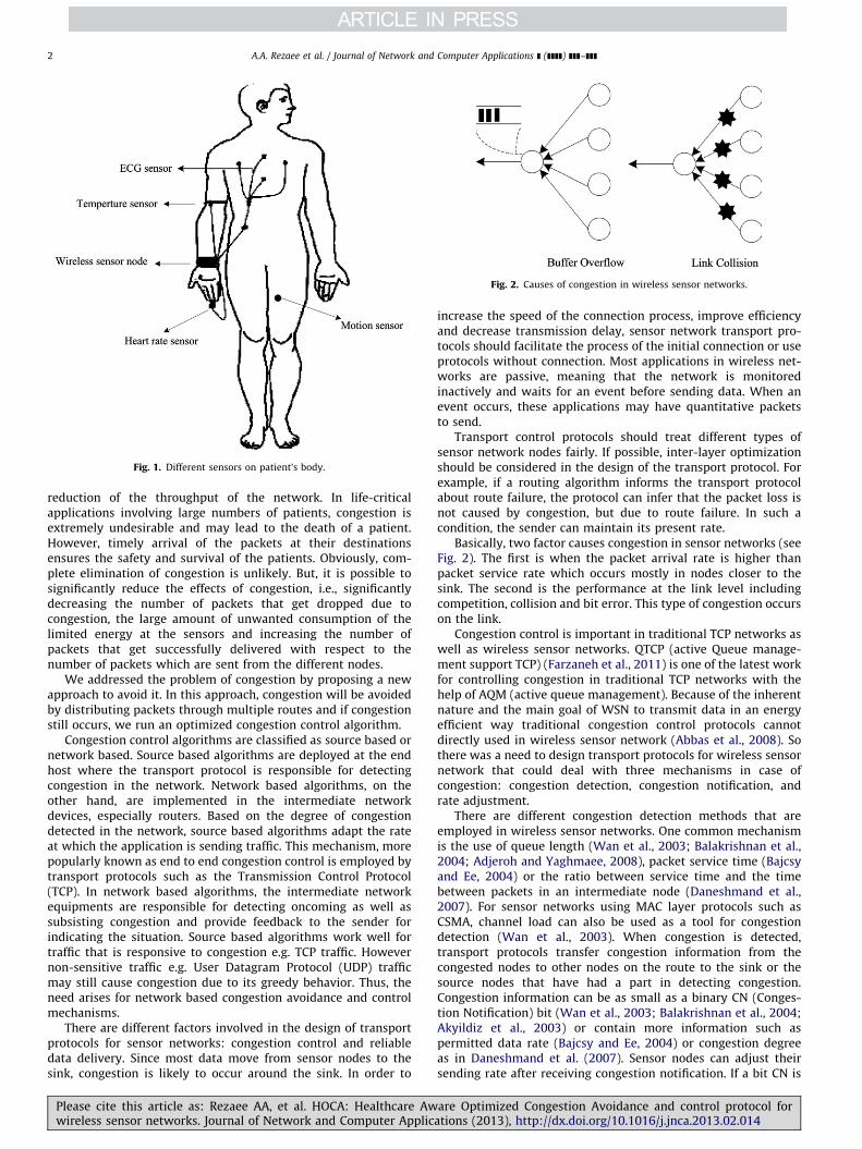
Fig. 1. Different sensors on patient’s body.
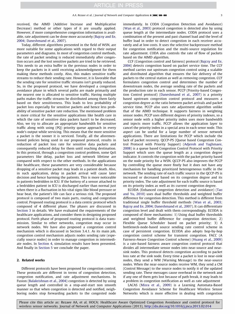
Fig. 2. Causes of congestion in wireless sensor networks.
A.A. Rezaee et al. / Journal of Network and Computer Applications ] (]]]]) ]]]–]]]2
reduction of the throughput of the network. In life-criticalapplications involving large numbers of patients, congestion isextremely undesirable and may lead to the death of a patient.However, timely arrival of the packets at their destinationsensures the safety and survival of the patients. Obviously, com-plete elimination of congestion is unlikely. But, it is possible tosignificantly reduce the effects of congestion, i.e., significantlydecreasing the number of packets that get dropped due tocongestion, the large amount of unwanted consumption of thelimited energy at the sensors and increasing the number ofpackets that get successfully delivered with respect to thenumber of packets which are sent from the different nodes.
We addressed the problem of congestion by proposing a newapproach to avoid it. In this approach, congestion will be avoidedby distributing packets through multiple routes and if congestionstill occurs, we run an optimized congestion control algorithm.
Congestion control algorithms are classified as source based ornetwork based. Source based algorithms are deployed at the endhost where the transport protocol is responsible for detectingcongestion in the network. Network based algorithms, on theother hand, are implemented in the intermediate networkdevices, especially routers. Based on the degree of congestiondetected in the network, source based algorithms adapt the rateat which the application is sending traffic. This mechanism, morepopularly known as end to end congestion control is employed bytransport protocols such as the Transmission Control Protocol(TCP). In network based algorithms, the intermediate networkequipments are responsible for detecting oncoming as well assubsisting congestion and provide feedback to the sender forindicating the situation. Source based algorithms work well fortraffic that is responsive to congestion e.g. TCP traffic. Howevernon-sensitive traffic e.g. User Datagram Protocol (UDP) trafficmay still cause congestion due to its greedy behavior. Thus, theneed arises for network based congestion avoidance and controlmechanisms.
There are different factors involved in the design of transportprotocols for sensor networks: congestion control and reliabledata delivery. Since most data move from sensor nodes to thesink, congestion is likely to occur around the sink. In order to
Please cite this article as: Rezaee AA, et al. HOCA: Healthcare Awwireless sensor networks. Journal of Network and Computer Applic
increase the speed of the connection process, improve efficiencyand decrease transmission delay, sensor network transport pro-tocols should facilitate the process of the initial connection or useprotocols without connection. Most applications in wireless net-works are passive, meaning that the network is monitoredinactively and waits for an event before sending data. When anevent occurs, these applications may have quantitative packetsto send.
Transport control protocols should treat different types ofsensor network nodes fairly. If possible, inter-layer optimizationshould be considered in the design of the transport protocol. Forexample, if a routing algorithm informs the transport protocolabout route failure, the protocol can infer that the packet loss isnot caused by congestion, but due to route failure. In such acondition, the sender can maintain its present rate.
Basically, two factor causes congestion in sensor networks (seeFig. 2). The first is when the packet arrival rate is higher thanpacket service rate which occurs mostly in nodes closer to thesink. The second is the performance at the link level includingcompetition, collision and bit error. This type of congestion occurson the link.
Congestion control is important in traditional TCP networks aswell as wireless sensor networks. QTCP (active Queue manage-ment support TCP) (Farzaneh et al., 2011) is one of the latest workfor controlling congestion in traditional TCP networks with thehelp of AQM (active queue management). Because of the inherentnature and the main goal of WSN to transmit data in an energyefficient way traditional congestion control protocols cannotdirectly used in wireless sensor network (Abbas et al., 2008). Sothere was a need to design transport protocols for wireless sensornetwork that could deal with three mechanisms in case ofcongestion: congestion detection, congestion notification, andrate adjustment.
There are different congestion detection methods that areemployed in wireless sensor networks. One common mechanismis the use of queue length (Wan et al., 2003; Balakrishnan et al.,2004; Adjeroh and Yaghmaee, 2008), packet service time (Bajcsyand Ee, 2004) or the ratio between service time and the timebetween packets in an intermediate node (Daneshmand et al.,2007). For sensor networks using MAC layer protocols such asCSMA, channel load can also be used as a tool for congestiondetection (Wan et al., 2003). When congestion is detected,transport protocols transfer congestion information from thecongested nodes to other nodes on the route to the sink or thesource nodes that have had a part in detecting congestion.Congestion information can be as small as a binary CN (Conges-tion Notification) bit (Wan et al., 2003; Balakrishnan et al., 2004;Akyildiz et al., 2003) or contain more information such aspermitted data rate (Bajcsy and Ee, 2004) or congestion degreeas in Daneshmand et al. (2007). Sensor nodes can adjust theirsending rate after receiving congestion notification. If a bit CN is
are Optimized Congestion Avoidance and control protocol forations (2013), http://dx.doi.org/10.1016/j.jnca.2013.02.014i
A.A. Rezaee et al. / Journal of Network and Computer Applications ] (]]]]) ]]]–]]] 3
received, the AIMD (Additive Increase and MultiplicativeDecrease) method or other types of it are usually applied.However, if more comprehensive congestion information is avail-able, rate adjustment can be done more accurately (Bajcsy and Ee,2004; Daneshmand et al., 2007).
Today, different algorithms presented in the field of WSN, aremore suitable for some applications with regard to their outputparameters and diagrams. In most of congestion control methods,the rate of packet sending is reduced immediately after conges-tion occurs and the lost sensitive packets are tried to be retrieved.This needs to an extra buffer in the previous nodes in order tokeep the packets in it until receiving acknowledgment for themmaking these methods costly. Also, this makes sensitive trafficstreams to reduce their sending rate. However, it is favorable thatthe sending rate for sensitive traffic streams isn’t greatly reduced.So, in the proposed protocol, we have developed a congestionavoidance phase in which several paths are made primarily andthe nearest one is allocated to sensitive traffic. Having multiplepaths makes the traffic streams be distributed among them fairlybased on their sensitiveness. This leads to less probability ofpacket loss especially for sensitive packets and hence less prob-ability of sensitive packet rate reduction. The mentioned problemis more critical for the sensitive applications like health care inwhich the rate of sensitive data packets hasn’t to be decreased.Also, we try to allocate an appropriate bandwidth for sensitivetraffic along with using (PQ) priority queue approach in everynode’s output while servicing. This means that the more sensitivea packet is the sooner it is serviced. Totally, all the aforemen-tioned policies being used in our proposed protocol, results inreduction of packet loss rate for sensitive data packets andconsequently reduced delay for them until reaching destination.In this protocol, through a congestion control problem, some QoSparameters like delay, packet loss and network lifetime arecompared with respect to the other methods. In the applicationslike healthcare, these parameters are very considerable becausedropping of a sensitive packet may leads in a patient death. Also,in such application, delay in packet arrival will cause laterdecision and hence harming the patients. This is more noticeablein patients bedridden in ICU. If the battery of a sensor attached toa bedridden patient in ICU is discharged earlier than normal justwhen there is a fluctuation in his vital signs like blood pressure orhear beat, the patient’s life can face a serious risk. The proposedprotocol is composed of two main parts, routing and congestioncontrol. Proposed routing protocol is a data centric protocol whichcomposed of 4 different phase. The phases are discussed inSection 3 in details. We have evaluated the requirements of thehealthcare applications, and consider them in designing proposedprotocol. Forth phase of proposed routing protocol is data trans-mission. Similar to other networks, congestion may occur innetwork nodes. We have also proposed a congestion controlmechanism which is discussed in Section 3.4.1. As its main job,congestion control mechanism adjusts nodes sending rate (espe-cially source nodes) in order to manage congestion in intermedi-ate nodes. In Section 4, simulation results have been presented.And finally in Section 5 we conclude the paper.
2. Related works
Different protocols have been proposed for congestion control.These protocols are different in terms of congestion detection,congestion notification, and rate adjustment mechanisms. InFusion (Balakrishnan et al., 2004) congestion is detected by usingqueue length and controlled in a stop-and-start non smoothmanner so that when congestion is detected and notified, neigh-boring nodes stop forwarding packets to the congested node
Please cite this article as: Rezaee AA, et al. HOCA: Healthcare Awwireless sensor networks. Journal of Network and Computer Applic
immediately. In CODA (Congestion Detection and Avoidance)(Wan et al., 2003) protocol congestion is detected also by usingqueue length at the intermediate nodes. CODA protocol uses acombination of the present and past channel load and the level ofbuffer load in order to detect congestion in each receiver accu-rately and at low costs. It uses the selective backpressure methodfor congestion notification and the multi-source regulation forrate adjustment. CODA also controls the rate of flow of packetsbased on the AIMD algorithm.
CCF (Congestion control and fairness) protocol (Bajcsy and Ee,2004) detects congestion based on packet service time. The CCFmethod carries out upstream congestion control using a scalableand distributed algorithm that ensures the fair delivery of thepackets to the central station as well as removing congestion. CCFformulates congestion control and determines the number ofdownstream nodes, the average sending rate of the packets andthe production rate in each sensor. PCCP (Priority-based Conges-tion Control protocol) (Daneshmand et al., 2007) is a prioritybased upstream congestion control protocol and measures acongestion degree as the ratio between packet arrivals and packetservice time. PCCP also uses rate adjustment algorithm unlikethat of the AIMD technique. It supports fairness in weightingsensor nodes. PCCP uses different degrees of priority indexes, so asensor node with a higher priority index uses more bandwidthand injects more traffic. PCCP allows the application layer tocancel the priority index in a special area in each senor node. Thisaspect can be useful for a large number of sensor networkapplications. There are limitations for PCCP which include thelack of packet recovery. QCCP-PS (Queue based Congestion Con-trol Protocol with Priority Support) (Adjeroh and Yaghmaee,2008) is a queue based Congestion Control Protocol with PrioritySupport which uses the queue length as a congestion degreeindicator. It controls the congestion with the packet priority basedon the node priority for a WSN. QCCP-PS also improves the PCCPby controlling the queue more finely but it does not have anymechanism for handling prioritized heterogeneous traffic in thenetwork. The sending rate of each traffic source in the QCCP-PS isincreased or decreased based on its congestion degree and itspriority index. The rate adjustment for each traffic source is basedon its priority index as well as its current congestion degree.
ECODA (Enhanced congestion detection and avoidance) (Taoand Yu, 2010) uses dual buffer thresholds and weighted bufferdifference for congestion detection. This method is different fromtraditional single buffer threshold methods (Wan et al., 2003;Bajcsy and Ee, 2004; Daneshmand et al., 2007). It can differentiatecongestion level and dealt with them correspondingly. ECODA iscomposed of three mechanisms: 1) Using dual buffer thresholdsand weighted buffer difference for congestion detection; 2)Flexible Queue Scheduler based on packet priority; 3) Abottleneck-node-based source sending rate control scheme incase of persistent congestion. ECODA also adopts hop-by-hopcongestion control scheme for transient congestion. FACC (AFairness-Aware Congestion Control scheme) (Huang et al., 2009)is a rate-based fairness aware congestion control protocol thatdivides all intermediate sensor nodes into near-source and near-sink nodes. This protocol detects congestion according to packetloss rate at the sink node. Every time a packet is lost in near-sinknodes, they send a WM (Warning Message) to the near-sourcenodes. When the near-source nodes receive WM, they send a CM(Control Message) to the source nodes to notify it of the updatedsending rate. These messages cause overhead in the network andif any one of them gets lost because of path break, it may leads toa problem in congestion notification as well as rate adjustment
LACAS (Misra et al., 2009) is a Learning Automata-BasedCongestion Avoidance Scheme for Healthcare Wireless SensorNetworks which is more effective in dealing with congestion
are Optimized Congestion Avoidance and control protocol forations (2013), http://dx.doi.org/10.1016/j.jnca.2013.02.014i
A.A. Rezaee et al. / Journal of Network and Computer Applications ] (]]]]) ]]]–]]]4
problems in healthcare WSNs. The process of learning in thiswork is a learning loop consisting of the RE (Random Environ-ment), and the LA (Learning Automata). The LA tries to learn theoptimal action (send rate) offered by the RE. An important featureof LACAS is that it intelligently ‘‘learns’’ from the past andimproves its performance significantly as time progresses. Oneof the limitations of this work is that its environment offers onlybinary responses for any action selected by the automaton.
Table 1 presents the characteristics of some of popular con-gestion control protocols.
In ESRT (Event-to-Sink Reliable Transport) (Akyildiz et al.,2003), the node monitors the congestion notification bit whichis located in the packet header and obtains a common rate for allsensors so that no packet is lost. This method supports fairnessbut all sensors cannot adapt to the worst rate in the congestionsituation. In this method, a new congestion control patterncapable of fair allocation of bandwidth is proposed. Of course,we expect that each flow should have a fair share of thebandwidth based on its production rate. In sensor networks, boththe number of active flows and the accessible bandwidth changewith time. Therefore, we cannot consider a fixed rate for eachflow. In order to achieve a fair sharing of the bandwidth, thefollowing method has been proposed.
3. The proposed protocol
The proposed protocol has been designed for congestionmanagement in wireless sensor networks for healthcare applica-tions. The main objective of the proposed protocol is to avoid, or ifnot possible, control congestion in wireless sensor networks.Similar to other data centric protocols such as REEP (Misraet al., 2008), Directed diffusion (Jang, 2007) and TPGF (Two-Phasegeographic Greedy Forwarding) (Shu et al., 2010) HOCA has beendeveloped in different phases. All these protocols use differentphases to perform different crucial tasks. TPGF (Shu et al., 2010)also uses multipath transmission. And they are all developed forwireless sensor networks. HOCA considers two main parameters,energy and delay (besides lifetime and fairness). In all routingprotocols which are developed for WSN, energy should beconsidered as a goal parameter. Delay is the main goal parameterfor healthcare applications. HOCA considers two types of traffics:sensitive and non-sensitive. Sensitive traffics are designed totransfer high priority data (they need low delay) and non-sensitive traffic is designed to transfer normal traffic.
The proposed protocol works in the following phase: 1)request dissemination which is performed by the sink, 2) eventoccurrence report which is performed using packets that areforwarded from sensors located on patients body to the sink,3) route establishment, 4) data forwarding and rate adjustment incase of congestion occurrence. In the design of HOCA, congestioncontrol as the main objective affects other objectives. Routinghas been considered as a part of the general objective. In thisprotocol, data are sent with different priorities. Therefore it can be
Table 1Congestion control protocols for wireless sensor networks.
Protocol Congestion detection
Fusion (Balakrishnan et al., 2004) Queue length
CODA (Wan et al., 2003) Queue length and channel state
CCF (Bajcsy and Ee, 2004) Packet service time
PCCP (Daneshmand et al., 2007) Packet interval time and packet service
QCCP-PS (Adjeroh and Yaghmaee, 2008) Queue length
ECODA (Tao and Yu, 2010) Dual buffer thresholds and weighted bu
FACC (Huang et al., 2009) Packet Drop At the Sink node
Please cite this article as: Rezaee AA, et al. HOCA: Healthcare Awwireless sensor networks. Journal of Network and Computer Applic
used for healthcare remote monitoring applications whose net-works contain data with different levels of importance anddifferent priorities for different patients.
The proposed protocol acts as a cross layer. As mentionedbefore, in HOCA the duties of transport layers and the network arecarried out simultaneously. First, the sink (the telemedicinecenter) sends its requirements (required information) to networknodes (sensors connected to the patient’s body). In the meantime,any network node observing the event specified by the sink, willinform the sink with an event report (patient’s condition) usingthe phase 2 procedure. In the second phase, the initial routingtables are formed. These tables are then used in the third phasewhere different routes are chosen in the final routing tables. Thefinal tables are produced in the third phase depending on thepriority of the transferred data. The fourth phase is the dataforwarding phase in which the data recorded from the eventsobserved by nodes are given to the sink. A large volume of data ismoved in this phase; therefore a procedure for congestion controlis needed. In HOCA, an adaptive procedure has been proposed forcontrolling source sending rates. This procedure is also carried outin the fourth phase in case of congestion.
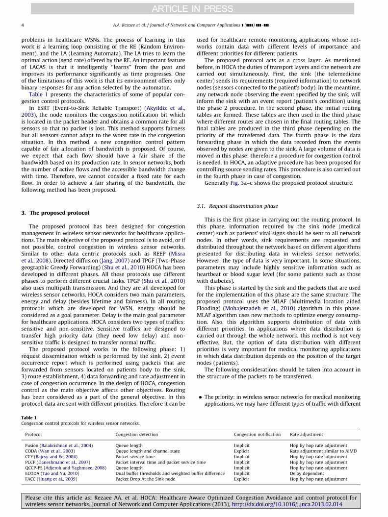
Generally Fig. 3a–c shows the proposed protocol structure.
3.1. Request dissemination phase
This is the first phase in carrying out the routing protocol. Inthis phase, information required by the sink node (medicalcenter) such as patients’ vital signs should be sent to all networknodes. In other words, sink requirements are requested anddistributed throughout the network based on different algorithmspresented for distributing data in wireless sensor networks.However, the type of data is very important. In some situations,parameters may include highly sensitive information such asheartbeat or blood sugar level (for some patients such as thosewith diabetes).
This phase is started by the sink and the packets that are usedfor the implementation of this phase are the same structure. Theproposed protocol uses the MLAF (Multimedia location aidedFlooding) (Mohajerzadeh et al., 2010) algorithm in this phase.MLAF algorithm uses new methods to optimize energy consump-tion. Also, this algorithm supports distribution of data withdifferent priorities. In applications where data distribution iscarried out through the whole network, this method is not veryeffective. But, the option of data distribution with differentpriorities is very important for medical monitoring applicationsin which data distribution depends on the position of the targetnodes (patients).
The following considerations should be taken into account inthe structure of the packets to be transferred.
�
tim
ffer
areatio
The priority: in wireless sensor networks for medical monitoringapplications, we may have different types of traffic with different
Congestion notification Rate adjustment
Implicit Hop by hop rate adjustment
Explicit Rate adjustment similar to AIMD
Implicit Hop by hop rate adjustment
e Implicit Hop by hop rate adjustment
Implicit Hop by hop rate adjustment
difference Implicit Delay dependent
Explicit Hop by hop rate adjustment
Optimized Congestion Avoidance and control protocol forns (2013), http://dx.doi.org/10.1016/j.jnca.2013.02.014i
Fig. 3. (a) Flowchart of Phase 1 and Phase 2 in congestion avoidance part. (b) Flowchart of Phase 3 and Phase 4 in congestion avoidance part. (c) Flowchart of Phase
4 congestion control part.
A.A. Rezaee et al. / Journal of Network and Computer Applications ] (]]]]) ]]]–]]] 5
Pw
characteristics. Therefore, while transferring a request, the typeof patient and its priority should be specified.
� Time: we may have several requests for a certain patient indifferent points in time. The time of each request should be
lease cite this article as: Rezaee AA, et al. HOCA: Healthcare Awareireless sensor networks. Journal of Network and Computer Applicatio
specified so that the nodes can determine the order oftransmission for different requests. However, requests forsome patients have an expiry period. After the end of theperiod the request is not considered anymore.
Optimized Congestion Avoidance and control protocol forns (2013), http://dx.doi.org/10.1016/j.jnca.2013.02.014i
A.A. Rezaee et al. / Journal of Network and Computer Applications ] (]]]]) ]]]–]]]6
�
Characteristics of the request: each request should contain theduties of the sensors connected to the patient’s body. Thespecification of how these requests are answered should alsoexist in the nodes.The above conditions are first met and then the packets aredistributed in the network. For example, in a medical monitoringapplication the above conditions for a request (patient statusreport request) are defined in the following manner, respectively:
�
Pw
Usually, in medical monitoring applications data related tovital signs have high priority; therefore this type of request isassigned a high priority. Also, we can consider other types oftraffics for data related to patient movements which have alower priority.
� Request dissemination time is set as the present time. � It is specified in the request that each sensor on the patient’sbody should report vital signs out of the normal range to thesink with high sensitivity. The normal range is determined bythe expert.
3.2. Event report phase
After the request dissemination phase, if a sensor senses anevent based on its duty, it will report the sign to the sinkaccording to the specifications. The report must have the requiredcharacteristics so that the sink can show the proper reaction.
In this phase, the information related to the occurring event issent to the sink, however basic data related to the event are sentin the data forwarding phase. Moreover, the preliminaries ofpacket routing are also determined in this phase. For this purpose,the patient node creates a packet containing the informationrelated to the sensed event and sends it to all its neighbors. Sincenodes (patients) are aware of their own positions the packets aresent to the neighbors that are closer to the sink than the sender.The routing tables required for the routing of node data in theroute from the packet to the sink will be provided. And the finalrouting will be carried out in the route forming phase.
After creating the packet (which we call phase 2 packet), if thenodes are aware of their positions this will lead to lower energyconsumption for the protocol. However since we need to locate allthe nodes it cannot be applied everywhere. It is worth noting thatin applications where the request should only be sent to part ofthe network, nodes are aware of their positions.
After receiving the packet from phase 2, each node creates arecord labeled phase 2 table in a routing table. The priority of thepacket (compared to the priority of the traffic and the event inquestion), the source node, the sender, the length of the coveredroute and the number of covered hops are kept in this record. Inthe proposed protocol, each node has an ID that is placed in alloutgoing packets. The length of the covered route is obtainedfrom the length of the route from the source of the packet to thecurrent node. After creating the record, the node sends the packetback to its neighbors. This procedure is repeated until the packetreaches the sink.
Note that from any source, there could be more than onerecord in each node’s phase 2 table. The reason for this is thatphase 2 packets may arrive at a node from different routes. Onlypackets with identical fields are ignored.
At the end of phase 2, each node has a routing table calledphase 2, table which is used for final routing in phase 3. Recordsin phase 2 routing table determine the possible routes betweenthe desired node and the source node sensing the event. AppendixA presents the pseudo code related to the phase 2 mechanism.
lease cite this article as: Rezaee AA, et al. HOCA: Healthcare Awireless sensor networks. Journal of Network and Computer Applic
3.3. Route establishment phase
After the arrival of phase 2 packets at the sink, a type3 confirmation packet is sent to the source node by the sinkwhich notifies the source node to send its data to the sink forprocessing. Then, sensors from one or more patient(s) may sendmessages. In this stage, the sink chooses one or several nodes forthe final transfer of data based on the information sent fromsource nodes. In phase 2 packets, each node specifies the level ofits importance. For example, the heart beat sensor or the kines-thetic sensor connected to the patient’s foot sends a message tothe center and specifies the level of importance. The sink choosesthe source node for the patient’s report based on the specifiedlevel of importance.
Following the selection of the source, phase 3 packets are sent.As the phase 3 packet moves along the route, it creates a phase3 routing table. Phase 3 routing table is the final routing table forrouting the data sent from the source. The transfer confirmationdepends on the priority of the sensed event. Two types ofconfirmations are considered, high priority confirmation (sensi-tive traffic) and low priority confirmation (non-sensitive traffic).
The sink checks the phase 2 routing table in order to send ahigh priority confirmation. The first record is chosen for sendingconfirmation. Phase 2 packets are then arranged chronologicallyin the phase 2 routing. Upon receiving a type 2 packet, the nodesplace it in the first record. In fact, the number assigned to thepacket record in the phase 2 routing table determines their timesequence. Since time is very important insensitive applications,the first record in the phase 2 routing table which is chronologi-cally the first created record is chosen. However, in choosingrecords, the source node in the record is always considered.Moreover, only records in which the source node is the onechosen by the sink will be considered.
Each node forms two tables in phase 3: Phase 3 routing tablewith high priority and phase 3 routing table with low priority.During this phase, two tables are completed. Routing table of eachnode maintains the best routes to the sink through its neighborswhich are closer to the sink. Considering the maximum number ofneighbors for each node in WSN, the routing table will bepractical and small.
When a node receives a phase 3 packet with high priority, itcreates a high priority record for the packet in the phase 3 routingtable. This table consists of the following components: sender(the source node of the receiving phase 3 packet with highpriority), receiver (the destination node for the phase 3 packetwith high priority), source node (the node sensing the eventwhich is the final destination of the phase 3 packet) and type ofapplication (this component will be used in networks designedfor multiple applications). Based on what has been mentioned sofar, each node chooses the first record from the phase 2 routingtable as the next hop for the high priority phase 3 packets. Thisprocedure will continue until the packet reaches the source. Infact, at the end of phase 3, a record is placed in the sensitive phase3 routing table for each source.
What has so far been mentioned in Section 3.3 is related tohigh priority traffic. We will go on to explain the creation of lowpriority phase 3 routing table. From among the records in thephase 2 routing table, the sink considers the records chosen inrelation to the source. For each of these records, the probabilityRSPi is computed using the following equation:
RSPi ¼TDi=HCiP
for all jASelected RecordsðTDi=HCiÞð1Þ
where TDi is the route length and HCi is the number of hops forthe ith record route. RSPi is the route select probability of choosingthe record as the next hop for the low priority phase 3 packets.
are Optimized Congestion Avoidance and control protocol forations (2013), http://dx.doi.org/10.1016/j.jnca.2013.02.014i
A.A. Rezaee et al. / Journal of Network and Computer Applications ] (]]]]) ]]]–]]] 7
After determining RSPis for all the records with the intendedsource, two records are chosen based on probability. Then, thelow priority phase 3 packet is sent to these records. Differentroutes are chosen so that fairness is observed in energy consump-tion of the network nodes.
Each node receives a phase 3 packet with low priority andrecords it in its routing table. Then, through a procedure similar tothat of the sink, the next two neighboring hop neighbors are chosenand the phase 3 packet is sent to them. All the characteristics arerecorded in non-sensitive phase 3 routing records. Appendix Bpresents the pseudo code related to the phase 3 mechanism.
3.4. Data forwarding phase
Towards the end of phase 3, sensitive and non-sensitive phase3 routing tables are created. Each node will contain asensitivephase 3 routing table and anon-sensitive phase 3 routing table.This provides multipath routing for our proposed protocol andcan distribute packets through more than one path.
Depending on the type of the sensed event, the source node(the node sensing the event) can send its data to the sink afterreceiving sensitive traffic from phase 3. As mentioned before, allnodes including the source node have two types of routing table.Sensitive phase 3 routing table is used for sending sensitive dataand non-sensitive phase 3 routing table is used for sending non-sensitive data.
In the sensitive phase 3 routing table, there is only one recordtoward the sink for each source. Each node receives sensitivetraffic from the node in question and uses the traffic to send therecord to the next hop. However, in each non-sensitive phase3 routing table, there will be more than one record for each sourcein the table. Each record has a probability RSPi based on which thenext hop is chosen. The greater the RSPi in the record, the morelikely it will be chosen. Finally, a record will be chosen as the nexthop and data are sent to this record.
Appendix C presents the pseudo-code related to the phase4 mechanism.
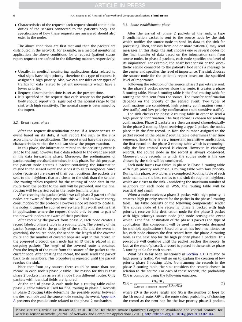
3.4.1. Congestion control mechanism in intermediate nodes
Our goal is to provide routing and congestion management inWSN’s for healthcare applications. Congestion management com-prises two phases: Congestion avoidance and congestion control.Congestion avoidance is implemented by distributed routingalgorithm (Section 3).
AQM schemes are one of the important mechanisms thatprovide quality of service and prevent congestion in IP networksthat perform special operations in our protocol to achieve betterperformance for end flows. With these mechanisms, congestion iscontrolled and network degradation is avoided (Borden andFiroiu, 2000). Figure 4 depicts the queuing model on an inter-mediate node. In this figure a classifier has been provisioned innetwork layer. The purpose of a classifier is to classify differenttypes of data and route them in their corresponding queues.
Fig. 4. The structure of an intermediate sensor node.
Please cite this article as: Rezaee AA, et al. HOCA: Healthcare Awwireless sensor networks. Journal of Network and Computer Applic
The type of data is located in the packet header. We define threetype of traffic; high priority, low priority and control packets.Sensitive traffics are sent to class 1, non-sensitive traffic sent toclass 2 and control packets are sent to class 3.
In our proposed protocol the CBWFQ (Class Based WeightedFair Queue) scheduler (Fischer et al., 2008) is used with theaddition of a PQ (Priority Queue). The use of PQ ensures lowlatency and more reliability for sensitive traffics. PQ allowssensitive traffics to be dequeued and sent first. While there is aclass 1 packet in the queue, the scheduler sends class 1 packetsout of queue. In order to provide fairness between class 1 andother classes, only 20 percent of network bandwidth is assignedto class 1 traffics, so using PQ scheduler does not cause unfairness.Indeed fewer queuing delays for class 1 traffics results from PQscheduler which use for sensitive traffics.
3.4.1.1. Proposed AQM. AQM (Active queue management) hasbeen proposed as a solution of preventing packet loss due tobuffer overflow. In a network, if the queue length isn’t suitablymanaged, the senders will continue sending the packets at theinitial rate leading to packet loss. Therefore, using AQM methods,the proposed protocol reduces sending rate of packet sendersbefore exceeding a determined threshold in order to prevent thepackets from being dropped. In a sensitive application like healthcare, packet loss is a very important problem which has to bereduced as much as possible.
Pi is the packet loss probability which is determined by activequeue management mechanism. HOCA uses a flexible procedure forqueue management. The proposed procedure shares the queue ineach node for the flows passing the node. However, the boundariesbetween queues are not fixed; meaning that if one of the activeflows has free space in its queue, other flows facing a lack of spacecan use this free space on certain conditions. In other words, queuesin Fig. 3 are separated virtually with flexible boundaries.
The probability of the drop (Pi) of a packet in ith queue isdetermined using the following equation:
Pi ¼ b1:dqvi�b2Uð1�ðXn
j ¼ 1
qj=QLÞÞþPprii ð2Þ
When a packet is received by the node, drop probability Pi iscomputed for the packet. Packet will be queued or dropped, basedon Pi value. In fact, higher probabilities of loss for a flow show thatthe corresponding queue is in critical status with respect to thecongestion. Therefore, the weight of Pi has been used directly indetermining the sending rate and the degree of congestion in eachnode. Ppri
i is an initial value for Pi which is determined using Eq. (3).qj presents the number of packets stored in jth virtual queue. dqvi
shows the level of variation in the length of the ith virtual queue.The value of dqvi can be positive or negative. dqvi is multiplied bycoefficient b1 as presented in Eq. (4). If dqvi is positive, it will remainpositive after multiplying by b1 and will finally cause an increase inPi. It means that if the variation in the flow queue length is positive(the queue size is prolonged) the packet loss probability and theprobability of congestion are increased. b2 specifies the flexibility ofthe flow queues. The expression
Pnj ¼ 1 qj specifies the total used
space in the node queue. Dividing the total by QL (total space in thenode queue) gives us the percentage of used space in the nodequeue. Multiplying this value by b2 will result in a number whichreduces the value of Pi. In other words, the greater the free space inthe queue the lesser the packet loss probability of the flows.However, the effect of this value depends on the b2 parameter. b1
and b2 are determined based on node priority by the user:
Pprii ¼
0 if : iqi!2UQL=3Un
n2:ðqi=QLÞ�2 if : qiZ2UQL=3Un
(ð3Þ
are Optimized Congestion Avoidance and control protocol forations (2013), http://dx.doi.org/10.1016/j.jnca.2013.02.014i
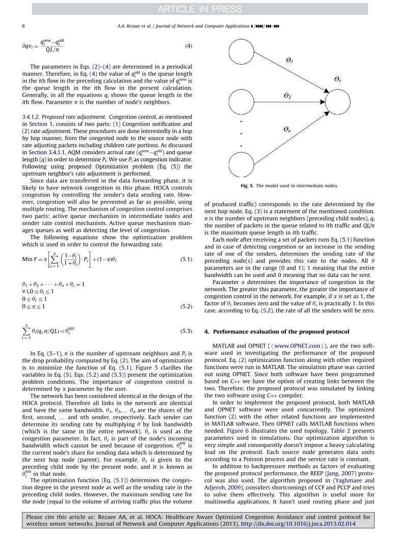
Fig. 5. The model used in intermediate nodes.
A.A. Rezaee et al. / Journal of Network and Computer Applications ] (]]]]) ]]]–]]]8
dqvi ¼qnew
i �qoldi
QL=nð4Þ
The parameters in Eqs. (2)–(4) are determined in a periodicalmanner. Therefore, in Eq. (4) the value of qold
i is the queue lengthin the ith flow in the preceding calculation and the value of qnew
i isthe queue length in the ith flow in the present calculation.Generally, in all the equations qi shows the queue length in theith flow. Parameter n is the number of node’s neighbors.
3.4.1.2. Proposed rate adjustment. Congestion control, as mentionedin Section 1, consists of two parts: (1) Congestion notification and(2) rate adjustment. These procedures are done interestedly in a hopby hop manner, from the congested node to the source node withrate adjusting packets including children rate portions. As discussedin Section 3.4.1.1, AQM considers arrival rate (qnew
i �qoldi ) and queue
length (q) in order to determine Pi. We use Pi as congestion indicator.Following using proposed Optimization problem (Eq. (5)) theupstream neighbor’s rate adjustment is performed.
Since data are transferred in the data forwarding phase, it islikely to have network congestion in this phase. HOCA controlscongestion by controlling the sender’s data sending rate. How-ever, congestion will also be prevented as far as possible, usingmultiple routing. The mechanism of congestion control comprisestwo parts: active queue mechanism in intermediate nodes andsender rate control mechanism. Active queue mechanism man-ages queues as well as detecting the level of congestion.
The following equations show the optimization problemwhich is used in order to control the forwarding rate.
Min F ¼ aXn
i ¼ 1
1�yi
1þyi
� �UPi
" #þð1�aÞyc ð5:1Þ
y1þy2þ � � � þynþyc ¼ 1
8 i,0ryir1
0ryc r1
0rar1 ð5:2Þ
Xn
i ¼ 1
yiðqi:n=QLÞ!yNHc ð5:3Þ
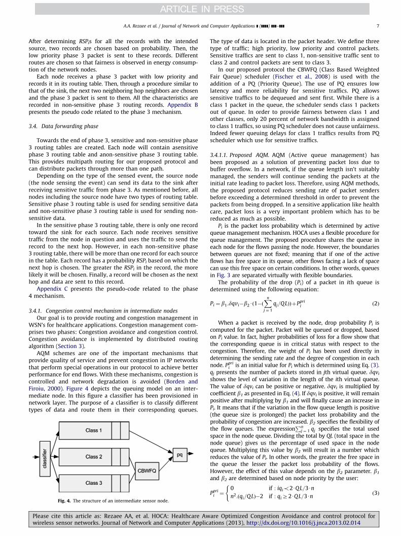
In Eq. (5–1), n is the number of upstream neighbors and Pi isthe drop probability computed by Eq. (2). The aim of optimizationis to minimize the function of Eq. (5.1). Figure 5 clarifies thevariables in Eq. (5). Eqs. (5.2) and (5.3)) present the optimizationproblem conditions. The importance of congestion control isdetermined by a parameter by the user.
The network has been considered identical in the design of theHOCA protocol. Therefore all links in the network are identicaland have the same bandwidth. y1, y2,y yn are the shares of thefirst, second, y and nth sender, respectively. Each sender candetermine its sending rate by multiplying y by link bandwidth(which is the same in the entire network). yc is used as thecongestion parameter. In fact, yc is part of the node’s incomingbandwidth which cannot be used because of congestion. yNH
c isthe current node’s share for sending data which is determined bythe next hop node (parent). For example, y1 is given to thepreceding child node by the present node, and it is known asyNH
c in that node.The optimization function (Eq. (5.1)) determines the conges-
tion degree in the present node as well as the sending rate in thepreceding child nodes. However, the maximum sending rate forthe node (equal to the volume of arriving traffic plus the volume
Please cite this article as: Rezaee AA, et al. HOCA: Healthcare Awwireless sensor networks. Journal of Network and Computer Applic
of produced traffic) corresponds to the rate determined by thenext hop node. Eq. (3) is a statement of the mentioned condition.n is the number of upstream neighbors (preceding child nodes), qi
the number of packets in the queue related to ith traffic and QL/n
is the maximum queue length in ith traffic.Each node after receiving a set of packets runs Eq. (5.1) function
and in case of detecting congestion or an increase in the sendingrate of one of the senders, determines the sending rate of thepreceding node(s) and provides this rate to the nodes. All yparameters are in the range (0 and 1); 1 meaning that the entirebandwidth can be used and 0 meaning that no data can be sent.
Parameter a determines the importance of congestion in thenetwork. The greater this parameter, the greater the importance ofcongestion control in the network. For example, if a is set as 1, thefactor of yc becomes zero and the value of yc is practically 1. In thiscase, according to Eq. (5.2), the rate of all the senders will be zero.
4. Performance evaluation of the proposed protocol
MATLAB and OPNET (/www.OPNET.comS), are the two soft-ware used in investigating the performance of the proposedprotocol. Eq. (2) optimization function along with other requiredfunctions were run in MATLAB. The simulation phase was carriedout using OPNET. Since both software have been programmedbased on Cþþ we have the option of creating links between thetwo. Therefore, the proposed protocol was simulated by linkingthe two software using Cþþ compiler.
In order to implement the proposed protocol, both MATLABand OPNET software were used concurrently. The optimizedfunction (2) with the other related functions are implementedin MATLAB software. Then OPNET calls MATLAB functions whenneeded. Figure 6 illustrates the used topology. Table 2 presentsparameters used in simulations. Our optimization algorithm isvery simple and consequently doesn’t impose a heavy calculatingload on the protocol. Each source node generates data unitsaccording to a Poisson process and the service rate is constant.
In addition to backpressure methods as factors of evaluatingthe proposed protocol performance, the REEP (Jang, 2007) proto-col was also used. The algorithm proposed in (Yaghmaee andAdjeroh, 2009), considers shortcomings of CCF and PCCP and triesto solve them effectively. This algorithm is useful more formultimedia applications. It hasn’t used routing phase and just
are Optimized Congestion Avoidance and control protocol forations (2013), http://dx.doi.org/10.1016/j.jnca.2013.02.014i
Table 2Simulation parameters.
Transmission range 40 m
Initial node energy 50 J
Type traffic Sensitive and non-sensitive
Network area 200�200 m2
Packet sent energy 12 mJ
Packet receive energy 10 mJ
Congestion detection epoch Each 50 packet
Fig. 7. Life time over traffic load.
Fig. 8. Mean remained energy over traffic load.
Fig. 6. The topology which is used in simulation.
A.A. Rezaee et al. / Journal of Network and Computer Applications ] (]]]]) ]]]–]]] 9
reduces the rate of sending nodes in occurrence of congestion.But, in sensitive applications like medical health care, it isn’tfavorable to reduce the sending rate of packets; meaning thatthrough allocating a proper bandwidth, it is tried to reduce thesending rate only for non-sensitive traffic not for sensitive one.Therefore, among routing algorithms, we chose REEP which is amulti-phase algorithm close to health care structure to becompared with our work. The major problem of REEP is ignoringthe priority and forwarding all the packets from the same path.Thus in the proposed algorithm, the REEP problem was solved viaa multi-path method along with support of packet prioritizing.REEP is a data-centric, energy efficient and reliable routingprotocol for WSNs. This protocol follows different phases likeother data centric protocols for routing which include: Senseevent propagation, Information event propagation and Requestevent propagation. REEP also uses an energy threshold value inorder to make the sensor nodes energy-aware. REEP also has fiveimportant elements, i.e. sense event, information event, requestevent, energy threshold value and request priority queue (RPQ).We use REEP besides back pressure in order to make a reasonablebasis to find the proposed protocol efficiency.
The proposed protocol uses MLAF (Mohajerzadeh et al., 2010)algorithm in the first phase. MLAF is specially designed for datadissemination in wireless sensor networks. Data centric Routingprotocol REEP uses Flooding to perform the first phase that has alower efficiency. MLAF algorithm prevents the wasting of energyby considering new method and provides the possibility of datatransmission with different priorities.
4.1. Energy performance comparison
Life time, remaining average energy and fairness are threeimportant factors that should be taken into account in evaluatingthe performance of the proposed protocol. Figures 7 and 8 illustratelifetime and remaining average energy of the network, respectively.The horizontal axis represents traffic load in kb/s and the vertical
Please cite this article as: Rezaee AA, et al. HOCA: Healthcare Awwireless sensor networks. Journal of Network and Computer Applic
axis represents lifetime per time unit. Network lifetime spans fromthe time the simulation is run until the first node dies.
As you can see in Fig. 7, the performance of HOCA is obvious incomparison with REEP from the view of traffic load, which areabout 400 packets per time unit. For example, at a traffic load of200 packets per time unit, HOCA increases lifetime in comparisonto REEP by about 78 percentages. HOCA uses multiple paths tosend data. This method ensures fair distribution of traffic at thedestination, which increases network life time while the REEPuses one way traffic transmission. We can see in Fig. 7 that HOCAhas a better performance than REEP in terms of network life time.
In Fig. 8, the mean of remaining node energy at the time ofdeath for the first node has been calculated. According to theresults in Fig. 8, the mean remaining energy in nodes for theHOCA protocol is less than REEP. The lower remaining energy is aresult of higher energy consumption.
If the nodes consume most of their energy until the end ofsimulations, the protocol is considered more successful. Of course,energy consumption with more attention to increase percentagein life time (Fig. 7) is acceptable.
As we mentioned before, respecting fairness on energy con-sumption is one of the powerful point of HOCA in energyperformance. If we can keep better balance in the energy con-sumption of nodes the lifetime of the network increases under thesame conditions. According to Fig. 9, fairness parameter is moresuccessful in HOCA rather than REEP one. Considered parameterhas calculated with Eq. (6). Eq. (6) calculates the variance ofnormalized remaining energy of network nodes to averageremained energy (Ave) of total network(In worst case half of thenodes get energy empty and half remain full, so if we normalize theequation we can achieve normalized fairness equation.). In Eq. (6),Energyi is node i remaining energy when simulations end.
are Optimized Congestion Avoidance and control protocol forations (2013), http://dx.doi.org/10.1016/j.jnca.2013.02.014i
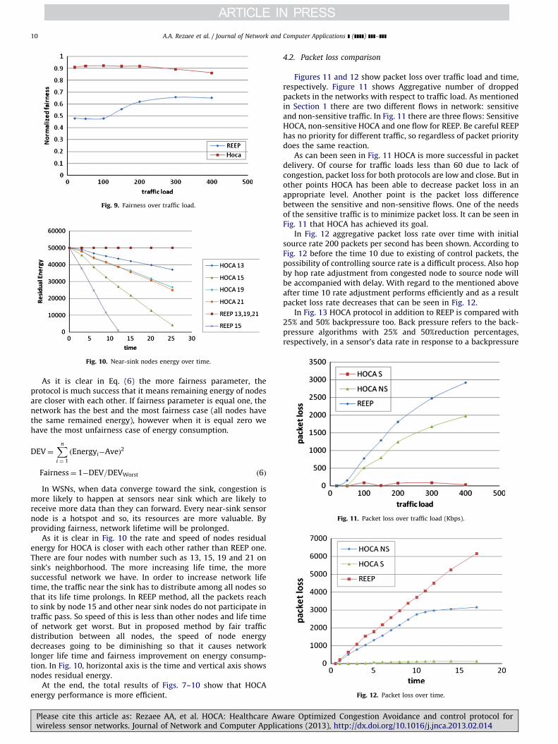
Fig. 9. Fairness over traffic load.
Fig. 10. Near-sink nodes energy over time.
Fig. 11. Packet loss over traffic load (Kbps).
Fig. 12. Packet loss over time.
A.A. Rezaee et al. / Journal of Network and Computer Applications ] (]]]]) ]]]–]]]10
As it is clear in Eq. (6) the more fairness parameter, theprotocol is much success that it means remaining energy of nodesare closer with each other. If fairness parameter is equal one, thenetwork has the best and the most fairness case (all nodes havethe same remained energy), however when it is equal zero wehave the most unfairness case of energy consumption.
DEV¼Xn
i ¼ 1
ðEnergyi�AveÞ2
Fairness¼ 1�DEV=DEVWorst ð6Þ
In WSNs, when data converge toward the sink, congestion ismore likely to happen at sensors near sink which are likely toreceive more data than they can forward. Every near-sink sensornode is a hotspot and so, its resources are more valuable. Byproviding fairness, network lifetime will be prolonged.
As it is clear in Fig. 10 the rate and speed of nodes residualenergy for HOCA is closer with each other rather than REEP one.There are four nodes with number such as 13, 15, 19 and 21 onsink’s neighborhood. The more increasing life time, the moresuccessful network we have. In order to increase network lifetime, the traffic near the sink has to distribute among all nodes sothat its life time prolongs. In REEP method, all the packets reachto sink by node 15 and other near sink nodes do not participate intraffic pass. So speed of this is less than other nodes and life timeof network get worst. But in proposed method by fair trafficdistribution between all nodes, the speed of node energydecreases going to be diminishing so that it causes networklonger life time and fairness improvement on energy consump-tion. In Fig. 10, horizontal axis is the time and vertical axis showsnodes residual energy.
At the end, the total results of Figs. 7–10 show that HOCAenergy performance is more efficient.
Please cite this article as: Rezaee AA, et al. HOCA: Healthcare Awwireless sensor networks. Journal of Network and Computer Applic
4.2. Packet loss comparison
Figures 11 and 12 show packet loss over traffic load and time,respectively. Figure 11 shows Aggregative number of droppedpackets in the networks with respect to traffic load. As mentionedin Section 1 there are two different flows in network: sensitiveand non-sensitive traffic. In Fig. 11 there are three flows: SensitiveHOCA, non-sensitive HOCA and one flow for REEP. Be careful REEPhas no priority for different traffic, so regardless of packet prioritydoes the same reaction.
As can been seen in Fig. 11 HOCA is more successful in packetdelivery. Of course for traffic loads less than 60 due to lack ofcongestion, packet loss for both protocols are low and close. But inother points HOCA has been able to decrease packet loss in anappropriate level. Another point is the packet loss differencebetween the sensitive and non-sensitive flows. One of the needsof the sensitive traffic is to minimize packet loss. It can be seen inFig. 11 that HOCA has achieved its goal.
In Fig. 12 aggregative packet loss rate over time with initialsource rate 200 packets per second has been shown. According toFig. 12 before the time 10 due to existing of control packets, thepossibility of controlling source rate is a difficult process. Also hopby hop rate adjustment from congested node to source node willbe accompanied with delay. With regard to the mentioned aboveafter time 10 rate adjustment performs efficiently and as a resultpacket loss rate decreases that can be seen in Fig. 12.
In Fig. 13 HOCA protocol in addition to REEP is compared with25% and 50% backpressure too. Back pressure refers to the back-pressure algorithms with 25% and 50%reduction percentages,respectively, in a sensor’s data rate in response to a backpressure
are Optimized Congestion Avoidance and control protocol forations (2013), http://dx.doi.org/10.1016/j.jnca.2013.02.014i
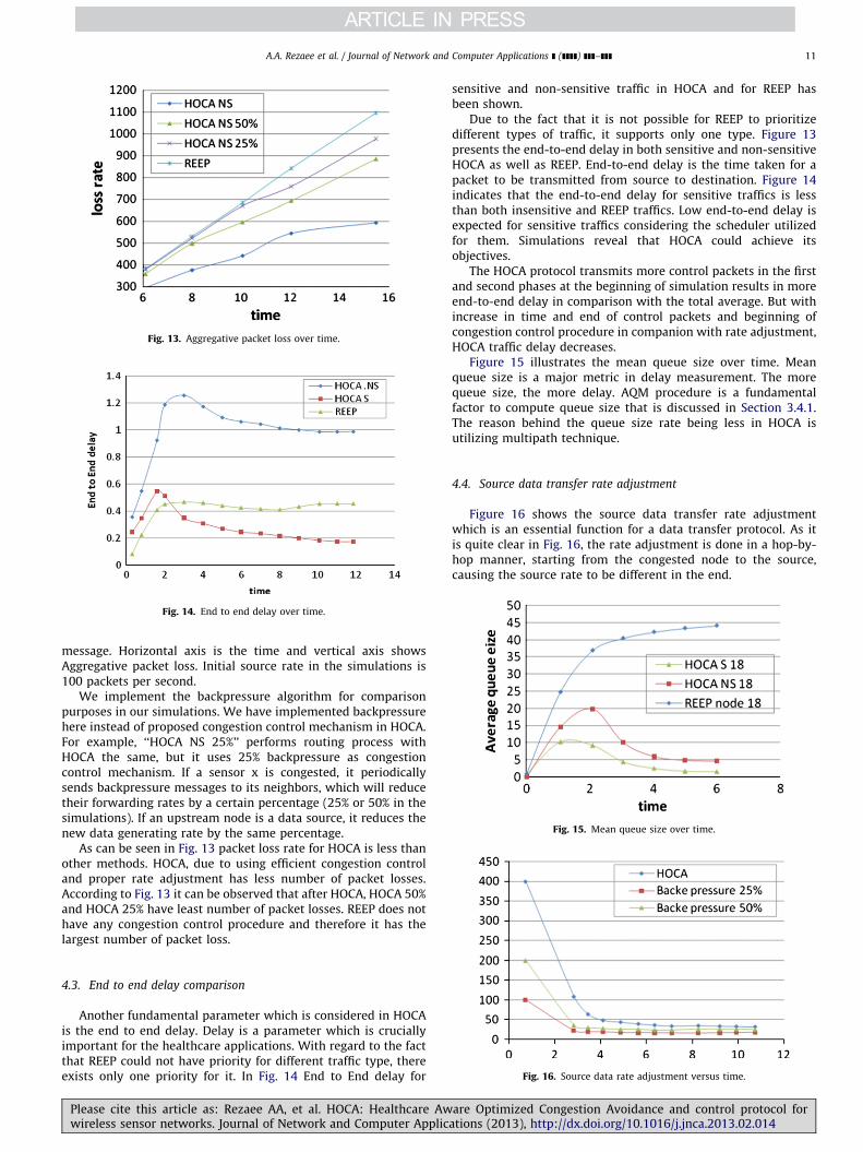
Fig. 13. Aggregative packet loss over time.
Fig. 14. End to end delay over time.
Fig. 15. Mean queue size over time.
A.A. Rezaee et al. / Journal of Network and Computer Applications ] (]]]]) ]]]–]]] 11
message. Horizontal axis is the time and vertical axis showsAggregative packet loss. Initial source rate in the simulations is100 packets per second.
We implement the backpressure algorithm for comparisonpurposes in our simulations. We have implemented backpressurehere instead of proposed congestion control mechanism in HOCA.For example, ‘‘HOCA NS 25%’’ performs routing process withHOCA the same, but it uses 25% backpressure as congestioncontrol mechanism. If a sensor x is congested, it periodicallysends backpressure messages to its neighbors, which will reducetheir forwarding rates by a certain percentage (25% or 50% in thesimulations). If an upstream node is a data source, it reduces thenew data generating rate by the same percentage.
As can be seen in Fig. 13 packet loss rate for HOCA is less thanother methods. HOCA, due to using efficient congestion controland proper rate adjustment has less number of packet losses.According to Fig. 13 it can be observed that after HOCA, HOCA 50%and HOCA 25% have least number of packet losses. REEP does nothave any congestion control procedure and therefore it has thelargest number of packet loss.
Fig. 16. Source data rate adjustment versus time.
4.3. End to end delay comparison
Another fundamental parameter which is considered in HOCAis the end to end delay. Delay is a parameter which is cruciallyimportant for the healthcare applications. With regard to the factthat REEP could not have priority for different traffic type, thereexists only one priority for it. In Fig. 14 End to End delay for
Please cite this article as: Rezaee AA, et al. HOCA: Healthcare Awwireless sensor networks. Journal of Network and Computer Applic
sensitive and non-sensitive traffic in HOCA and for REEP hasbeen shown.
Due to the fact that it is not possible for REEP to prioritizedifferent types of traffic, it supports only one type. Figure 13presents the end-to-end delay in both sensitive and non-sensitiveHOCA as well as REEP. End-to-end delay is the time taken for apacket to be transmitted from source to destination. Figure 14indicates that the end-to-end delay for sensitive traffics is lessthan both insensitive and REEP traffics. Low end-to-end delay isexpected for sensitive traffics considering the scheduler utilizedfor them. Simulations reveal that HOCA could achieve itsobjectives.
The HOCA protocol transmits more control packets in the firstand second phases at the beginning of simulation results in moreend-to-end delay in comparison with the total average. But withincrease in time and end of control packets and beginning ofcongestion control procedure in companion with rate adjustment,HOCA traffic delay decreases.
Figure 15 illustrates the mean queue size over time. Meanqueue size is a major metric in delay measurement. The morequeue size, the more delay. AQM procedure is a fundamentalfactor to compute queue size that is discussed in Section 3.4.1.The reason behind the queue size rate being less in HOCA isutilizing multipath technique.
4.4. Source data transfer rate adjustment
Figure 16 shows the source data transfer rate adjustmentwhich is an essential function for a data transfer protocol. As itis quite clear in Fig. 16, the rate adjustment is done in a hop-by-hop manner, starting from the congested node to the source,causing the source rate to be different in the end.
are Optimized Congestion Avoidance and control protocol forations (2013), http://dx.doi.org/10.1016/j.jnca.2013.02.014i
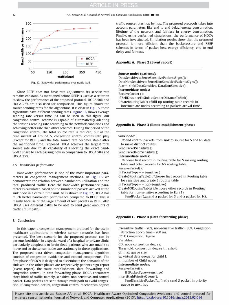
Fig. 17. Bandwidth performance over traffic load.
A.A. Rezaee et al. / Journal of Network and Computer Applications ] (]]]]) ]]]–]]]12
Since REEP does not have rate adjustment, its service rateremains constant. As mentioned before, REEP is used as a criterionto show the performance of the proposed protocol. HOCA 50% andHOCA 25% are also used for comparison. This figure shows thesource sending rates for the algorithms. It is clear in Fig. 15, thesealgorithms have different sending rates. Figure 16 shows averagesending rate versus time. As can be seen in this figure, ourcongestion control scheme is capable of automatically adaptingthe sensor’s sending rate according to the network conditions andachieving better rate than other schemes. During the period of thecongestion control, the total source rate is reduced, but at thetime instant of around 5, congestion control comes into play(except for REEP), and the total source rate becomes stable afterthe mentioned time. Proposed HOCA achieves the largest totalsource rate due to its capability of allocating the exact band-width share to each passing flow in comparison to HOCA 50% andHOCA 25%.
4.5. Bandwidth performance
Bandwidth performance is one of the most important para-meters in congestion management methods. In Fig. 16 wedemonstrate the relation between bandwidth utilization and thetotal produced traffic. Here the bandwidth performance para-meter is calculated based on the number of packets arrived at thesink node in a certain time unit. As is shown in Fig. 17, HOCA hasmuch better bandwidth performance compared to REEP. This ismainly because of the large amount of lost packets in REEP. AlsoHOCA uses different paths to be able to send great amounts oftraffic (multipath).
5. Conclusion
In this paper a congestion management protocol for the use inhealthcare applications in wireless sensor networks has beenpresented. The best scenario for the proposed protocol can bepatients bedridden in a special ward of a hospital or private clinic,particularly apoplectic or brain dead patients who are unable tomove and so the sensor nodes are stationary in these applications.The proposed data driven congestion management algorithmconsists of congestion avoidance and control components. Thefirst phase of HOCA is designed to disseminate the demands of thesink while the other phases are respectively patients sign report(event report), the route establishment, data forwarding andcongestion control. In data forwarding phase, HOCA encountersthree kinds of traffic, namely, sensitive, non-sensitive, and controlpacket. Data packets are sent through multipath to avoid conges-tion. If congestion occurs, congestion control mechanism adjusts
Please cite this article as: Rezaee AA, et al. HOCA: Healthcare Awwireless sensor networks. Journal of Network and Computer Applic
traffic source rates hop by hop. The proposed protocols takes intoaccount parameters like end to end delay, energy consumption,lifetime of the network and fairness in energy consumption.Finally, using performed simulations, the performance of HOCAhas been investigated. Simulation results show that the proposedprotocol is more efficient than the backpressure and REEPschemes in terms of packet loss, energy efficiency, end to enddelay and fairness.
Appendix A. Phase 2 (Event report)
Source nodes (patients):DataSensitive¼SenseSensitivePatientsSigns();DataNonSensitive¼SenseNonSensitivePatientsSigns();Alarm_sink(DataSensitive, DataNonSensitive);Intermeidate nodes:ReceivePacket ();If(SelfDistanceToSinkoSenderDistanceToSink)CreateRoutingTable();//fill up routing table records in
intermediate nodes according to packets arrival time
Appendix B. Phase 3 (Route establishment phase)
Sink node://Send control packets from sink to source for S and NS datato make distinct routes
SendPacketSensitive();SendPacketNonSensitive();Intermediate nodes:
//choose first record in routing table for S making routingtable and other records for NS routing table.
ReceivePacket();If(PacketType¼¼Sensitive )CreateSRoutingTable();//choose first record in Routing table
for sensitive and create S routing tableIf(PacketType¼¼non-Sensitive)CreateNSRoutingTable();//choose other records in Routing
table for non-sensitiveaccording to Eq. (1)SendPacket();//send a packet for S and a packet for NS.
Appendix C. Phase 4 (Data forwarding phase)
//sensitive traffic¼20%, non-sensitive traffic¼80%, Congestiondetection epoch time¼200 ms.
//CD: Congestion DegreeVariables:CD: node congestion degree.Threshold: congestion degree thresholdql: max queue size.qi: virtual data queue for child I.n: number of Child nodes.Intermediate nodes:ReceivePacket();
If (PacketType¼sensitive)InsertHighPriorityQueue();
SendSensitivePacket();//firstly send S packet in priorityqueue to next hop
are Optimized Congestion Avoidance and control protocol forations (2013), http://dx.doi.org/10.1016/j.jnca.2013.02.014i
A.A. Rezaee et al. / Journal of Network and Computer Applications ] (]]]]) ]]]–]]] 13
CongestionDetection();If (CD4Threshold )//congestion detected
{yNH¼ 1;
RateAdjusment (yNH);//Sending new Rates to child nodes ();SendRates();
If (Pi is high )//calculate packet loss Piwith Eqs. (4)and (5)
DeletePacket();else {//for records two and three other than first one
x¼Distance/HopCount;//record twoy¼Distance/HopCount;//record threePn1¼x/xþy;//probability of selecting record two for
next hopPn2¼ y/xþy;//probability of selecting record three for
next hopSendNonSensitivePacket();}
}
Congestion detection
If (PacketType¼non-sensitive)min¼2/3�ql/n;if (qi4min)
CD¼(3�n� qi�2�ql)/ql;Else
CD¼0.0;
Receiving rate share packets from parent to child nodes
CongestionDetection();
yNHnew¼a�y
NHold þ(1�a)� yNH));//a o1
RateAdjustment( Min(yNH,CD)//with formulas (2)
Node_service_rate¼MaxRatenp1ny1þMaxRatenp2n y2;Sending_ratei¼ Node_service_rate
yNHold ¼y
NHnew //for the next time
If (CD4Threshold)
If (yNH4 (1� CD))
yNH¼1 � CD;
References
Abbas C, Gonzalez R, et al. A proposal of a wireless sensor network routingprotocol. Telecommunication Systems 2008;38:61–8.
Please cite this article as: Rezaee AA, et al. HOCA: Healthcare Awwireless sensor networks. Journal of Network and Computer Applic
Adjeroh, D, Yaghmaee, H.. A new priority based congestion control protocol forwireless multimedia sensor networks. In: International symposium on a worldof wireless, mobile and multimedia networks, Newport beach, CA, USA, June23–26, 2008; 2008. p. 1–8.
Akkaya K, Younis M. A survey on routing protocols for wireless sensor networks.Ad Hoc Networks 2005;3:325–49.
Akyildiz IF, Su Y, Sankarasubramaniam W, C- ayirci E. Wireless sensor networks: asurvey. Computer Networks Journal 2002;38:393–422.
Akyildiz, IF, Akan, OB, Sankarasubramaniam, Y.. ESRT: Event-to-sink reliabletransport in wireless sensor networks. In: Proceedings of ACMMobihoc’03,June 1–3, 2003, Annapolis, Maryland; 2003.
Armijo, CRK, Belka, S, Benhabib, M, Leland, ES, Pering, T, Waterbury, A, et al..Wireless sensor networks for home health care. In: Proceedings 21st interna-tional conference on advanced information networking applications work-shops; 2007.
Bajcsy, R, Ee, C-T.. CCF: Congestion control and fairness for many-to-one routing insensor networks. In: Proceedings of ACM Sensys’04, November 3–5, 2004,Baltimore, Maryland, USA; 2004.
Balakrishnan, H, Hull, B, Jamieson, K.. Mitigating congestion in wireless sensornetworks. In: Proceedings of the ACM Sensys ’04, Baltimore, MD, November2004; 2004.
Borden, M, Firoiu, V.. A study of active queue management for congestion control.IEEE INFOCOM; 2000.
Cao, Q, Doan, T, Fang, L, He, Z., Kiran Lin, SR, Stankovic, JA, et al.. Wireless sensornetworks for in-home healthcare: Potential and challenges. In Proceedings ofthe high confidence medical device software systems (HCMDSS) workshop, June2005; 2005.
Cao, Q, Doan, T, Fang, L, He, Z, Lin, S, Selavo, L, et al.. Alarm-net: An assisted livingcentered and testbed-oriented information system based on residential wire-less sensor network. In: Proceedings of the transdisciplinary conferencedistributed diagnosis home healthcare; 2006.
Daneshmand M, Hu Y, Li B, Sohraby K, Wang C. Upstream congestion control inwireless sensor networks through cross-layer optimization. In IEEE Journal onSelected Areas in Communications 2007;25(4):786–95.
Farzaneh N, Monsefi R, et al. QTCP: a novel congestion control protocol with AQMsupport for IP-based networks. Telecommunication Systems 2011:1–16.
Fischer, M, Masi, D, Shortle, J. Approximating low latency queuing buffer latency.In: Fourth advanced international conference on telecommunications; 2008.
Huang R, Fang Y, Li S, Yin X, Zhou X. A fairness-aware congestion control scheme inwireless sensor networks. In IEEE Transactions on Vehicular Technology2009;58(9 (November)).
Jang J. A study on a sequenced directed diffusion algorithm for sensor networks.In: Proceedings of 9th ICACT, Gangwon-Do, Korea, February 2007; 2007. p.679–683.
Misra S, Rashvand HF, Zabin F, Woungang I. REEP: data-centric, energy-efficientand reliable routing protocol for wireless sensor networks. In IET Commu-nications 2008 2008;2(8):995–1008.
Misra S. Obaidat, M.S. Fellow, Tiwari V. LACAS: learning automata-based conges-tion avoidance scheme for healthcare wireless sensor networks. IEEE Journalon Selected Areas in Communications 2009;27(4(May)).
Mohajerzadeh, AH, Monsefi, R, Yaghmaee, MH. (. MLAF: A QoS based datadissemination protocol for wireless multimedia sensor networks. IEEE; 2010.
Shu L, Zhang Y, et al. TPGF: geographic routing in wireless multimedia sensornetworks. Telecommunication Systems 2010;44(1):79–95.
Sohraby, K, Wang, C.. A survey of transport protocols for wireless sensor networks.In: IEEE network magazine, May/June 2006; 2006. p. 34–40.
Tao LQ, Yu FQ. ECODA: enhanced congestion detection and avoidance for multipleclass of traffic in sensor networks. Transactions on Consumer Electronics2010;56(3).
Wan, C–Y, Eisenman, SB, Campbell, AT.. CODA: Congestion detection and avoid-ance in sensor networks. In: Proceedings of ACMSensys’03, November 5–7,2003, Los Angeles, California, USA; 2003.
/www.OPNET.comS.Yaghmaee MH, Adjeroh DA. Priority-based rate control for service differentiation
and congestion control in wireless multimedia sensor networks. ComputerNetworks 2009, . http://dx.doi.org/10.1016/j.comnet.2009.02.011.
are Optimized Congestion Avoidance and control protocol forations (2013), http://dx.doi.org/10.1016/j.jnca.2013.02.014i


![Journal of Network and Computer Applicationsw3.ualg.pt/~arahmani/index_files/A new fuzzy negotiation...2 S. Adabi et al. / Journal of Network and Computer Applications ] (]]]]) ]]]–]]]](https://img.pdfslide.net/doc/110x75/5abe5c057f8b9ab02d8cce52/journal-of-network-and-computer-arahmaniindexfilesa-new-fuzzy-negotiation2.jpg)