Embed Size (px)
Citation preview

ME 333 Introduction to Mechatronics Lab 1
1
LAB 1AN EXAMPLE MECHATRONIC SYSTEM: THE FURBY
Objectives To see the inner workings of a commercial mechatronic system and toconstruct a simple manual motor speed controller and current amplifier.
Preparation Read Lab 1 and the multimeter, breadboard, function generator, andoscilloscope tutorial web pages.
Tools Prototyping breadboard, power supply, multimeter, wire cutter/stripper,function generator, and oscilloscope.
1 Introduction
This first lab will introduce you to the equipment at your workstation, show you the innerworkings of a commercial mechatronic system, and demonstrate the basic elements ofmechatronic design.
2 The Furby
The Furby, made by Tiger Electronics, is a commercially successful robot pet. The oldversion, circa 2000, includes a single actuator with an interesting gearing system drivingthe eyelids, ears, mouth, and waist; a speaker for talking; custom-made microprocessors;and a variety of sensors such as a microphone, a light sensor, a tilt sensor, an infraredemitter and receiver, a motor encoder, and touch sensors. Despite having only a singleactuator, its innovative design allows it to exhibit a range of interesting behaviors.
The goal of this part of the lab is to understand the design of the Furby by identifying itsparts. We have already dissected it for you by removing its fur and plastic case.
Tasks
a. On the answer sheet, indicate each of the following parts of the Furby by labeling thelines with the appropriate numbers.
1. The +6V terminal. (The Furby takes four 1.5 V AA batteries.)2. The ground terminal.3. The Furby’s DC motor.4. The encoder.5. The light sensor.6. The “home” position sensor.7. The stomach touch sensor.
b. After this lab, you will have built a breadboard that looks something like the figurehanded out with the lab. Use this as a guide in building up your breadboard. Keep

ME 333 Introduction to Mechatronics Lab 1
2
things neat by cutting wires to length so that they run vertically or horizontally and lieflat on the breadboard.
We begin by hooking up the Furby cable and the power distribution strips, as shownin the accompanying figure.
o Connect the Furby I/O cable to the breadboard as shown in the figure, and connect theground and +5V lines to the distribution strips. To do this, use solid (not stranded) 22AWG wire (22 wire gauge; wires get bigger as the gauge decreases). Use black wirefor ground and red wire for +5V. Cut the wire from the spool and use your wirestripper to strip off approximately 1/4 inch of the insulation at each end of the wire.Do NOT connect the Furby power cable yet (we will not need this until the last partof the second lab).
o Hook up the power distribution strips to the binding posts.
Verify that your breadboard matches the figure.
3 The Manual Speed Control Circuit
We will build a manual speed control circuit and current amplifier. We could try to buildthe whole thing at once and test it. But this is never a good idea. Always build thepieces first, and once you are sure the individual pieces are working, put them together.If the whole system does not work now, then the problem is isolated to the interaction ofthe two subsystems.
In summary, always decompose the system into subsystems (and perhaps the subsystemsinto subsubsystems). Then build from the bottom up, making sure each subsystem worksas expected before connecting them together. This has the following benefits:o Makes it easier to isolate problems and prevent them from occurring.o Minimizes the potential for catastrophic failure, such as the output of one system
destroying a component of another system.
Our first problem is to build the motor control circuit. We divide this problem into twoparts. (1) We will design a manual speed control circuit which consists of a knob that theuser can turn to set a control signal between –5V and +5V. (2) We will build a currentamplifier circuit, which boosts the current from the speed control circuit to run the motor.Here we concentrate on the first part.
Tasks
a. Using your multimeter, measure the total resistance of the potentiometer (pot) givento you by the TA. Also, look at the resistance between one end of the pot and thewiper terminal as you rotate the knob.
Top view
wiper
ME 333 Introduction to Mechatronics Lab 1
3
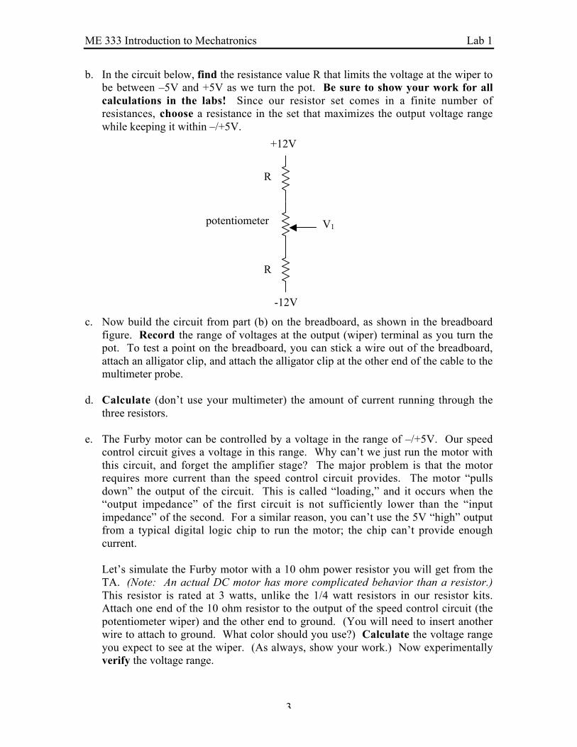
b. In the circuit below, find the resistance value R that limits the voltage at the wiper tobe between –5V and +5V as we turn the pot. Be sure to show your work for allcalculations in the labs! Since our resistor set comes in a finite number ofresistances, choose a resistance in the set that maximizes the output voltage rangewhile keeping it within –/+5V.
c. Now build the circuit from part (b) on the breadboard, as shown in the breadboardfigure. Record the range of voltages at the output (wiper) terminal as you turn thepot. To test a point on the breadboard, you can stick a wire out of the breadboard,attach an alligator clip, and attach the alligator clip at the other end of the cable to themultimeter probe.
d. Calculate (don’t use your multimeter) the amount of current running through thethree resistors.
e. The Furby motor can be controlled by a voltage in the range of –/+5V. Our speedcontrol circuit gives a voltage in this range. Why can’t we just run the motor withthis circuit, and forget the amplifier stage? The major problem is that the motorrequires more current than the speed control circuit provides. The motor “pullsdown” the output of the circuit. This is called “loading,” and it occurs when the“output impedance” of the first circuit is not sufficiently lower than the “inputimpedance” of the second. For a similar reason, you can’t use the 5V “high” outputfrom a typical digital logic chip to run the motor; the chip can’t provide enoughcurrent.
Let’s simulate the Furby motor with a 10 ohm power resistor you will get from theTA. (Note: An actual DC motor has more complicated behavior than a resistor.)This resistor is rated at 3 watts, unlike the 1/4 watt resistors in our resistor kits.Attach one end of the 10 ohm resistor to the output of the speed control circuit (thepotentiometer wiper) and the other end to ground. (You will need to insert anotherwire to attach to ground. What color should you use?) Calculate the voltage rangeyou expect to see at the wiper. (As always, show your work.) Now experimentallyverify the voltage range.
V1
+12V
R
R
-12V
potentiometer

ME 333 Introduction to Mechatronics Lab 1
4
f. The resistors in our resistor kit are 1/4 watt resistors, meaning that they should not beused to dissipate more than 1/4 watt of power. Remember, the power dissipated by aresistor is P = IV = V2/R = I2R. Based on the voltage range you observedexperimentally above, calculate the maximum power dissipated by the 10 ohmresistor.
g. Now disconnect the 10 ohm resistor. Based on the current in part (d), calculate howmuch power is dissipated by the speed control circuit. This power is dissipatedregardless if the motor is running or not. Notice a tradeoff: we can decrease theeffect of loading if we decrease the resistances of the resistors and pot in the speedcontrol circuit. However, this comes at the expense of more power being dissipatedby the speed control circuit, even when the motor is not running. In general, we wantto decouple “signal” circuits (the speed control circuit) and “power” circuits (thecurrent amplifier). We can design, test, and build them individually if the inputimpedances of the power circuits are much higher than the output impedances of thesignal circuits.
You have finished building the manual speed control circuit. We will build the currentamplifier next.
4 The Current Amplifier
The current amplifier we will build is a simple “push-pull” circuit. It consists of twopower transistors: one to “push” current through the motor, and one to “pull” currentthrough the motor, allowing us to run the motor in both directions. If we only wished torun the motor in one direction, a single transistor would suffice.
The operation of this circuit is quite simple. For sufficiently positive values of the inputvoltage, the TIP31 npn transistor will turn on, and the output voltage will be one diodedrop lower than the input voltage. Current flows from the +12V supply through themotor to ground. For sufficiently negative values of the input voltage, the TIP32 pnptransistor will turn on, and the output voltage will be one diode drop higher than the inputvoltage. Current flows from ground through the motor to the –12V supply.
VoutVin
+12V
-12V
Motor_+
TIP31
TIP32

ME 333 Introduction to Mechatronics Lab 1
5
This is a very simple amplifier. It has some undesirable properties, and we could dobetter by incorporating an operational amplifier and feedback, or by using pulse-widthmodulation. It may also be a good idea to protect the motor and amplifier usingadditional “flyback” diodes. These are topics for later in the course. For now, thissimple circuit will serve the purpose.
Tasks
a. Without dismantling the speed control circuit you have already built, build the push-pull amplifier circuit. The transistor on top is npn (TIP31) and the transistor on thebottom is pnp (TIP32). Do not connect the motor yet. Instead, use the 10 ohmresistor in its place; connect it at one end to the emitters and at the other end toground. Now connect the output of the speed control circuit V1 to the input of theamplifier circuit Vin. Record the max range of the voltage V1 = Vin as you turn thepot. Explain why it is or is not the same range you observed in part 3(c).
b. Turn the potentiometer so that V1 is -2V. Increase V1 slowly up to 2V, and recordthe range of V1 values for which Vout is approximately 0V. This is called the“deadband.” This deadband is an undesirable property of the amplifier, and caneasily be eliminated by the use of feedback as we will learn later.
c. Remove the 10 ohm resistor, and connect Vout to the + terminal of the motor. Turnthe pot and see how the Furby moves. Record the max ranges of the voltages Vin andVout as you turn the pot. Pay particular attention to the motion of the gears in theback. Draw a rough sketch of Vout vs. Vin on your answer sheet.
d. Turn off the power supply. We will measure the current flowing through the motor.Change the red lead of the multimeter to the 10A connection, and put the multimeterin series with the circuit: Vout goes to the red lead of the multimeter, and the blacklead of the multimeter goes to the + terminal of the motor (via wires attached to thebreadboard; again, you can use alligator clips). Now turn on the power supply, turnthe pot to its maximum setting (Vin is maximum), and record the maximum currentflowing through the motor. Turn off the power supply, take the multimeter out of thecircuit, and reattach the amplifier output directly to the + terminal of the motor.
e. Using your results from parts (c) and (d), calculate the power dissipated by atransistor when the pot is at its maximum setting. The power is the current multipliedby the voltage drop from the collector to the emitter. Notice that if you run the motorin one direction for a while, one transistor heats up while the other is cool. The onethat heats up is the one that is on. Feel the backs of the transistors to notice this (butbe careful not to get burned!). The power is dissipated as heat, and this is the reasonwe use metal heat sinks to conduct away the heat from power transistors,microprocessors, and other electrical elements that dissipate a lot of heat.

ME 333 Introduction to Mechatronics Lab 1
6
5 The Encoder Signal
As a motor rotates, an encoder generates a number of pulses proportional to the amountof rotation of the motor. By counting these pulses, we can keep track of the total amountof rotation. Our Furby has a simple type of encoder. A wheel with a hole in it rotateswith the motor, and a light beam sensor detects the hole as it passes the sensor. We willlearn about more sophisticated encoders later in the course.
We will build the circuit below. Everything to the left of the connector is alreadypresent; we will only build the portion to the right of the connector.
Tasks
a. Connect the Furby’s power cable to +5V and ground on the breadboard. This willpower the light emitting diode. Connect the green lead of the Furby cable to a 4.7 kΩresistor running to ground on the breadboard. (Do not build the rest of the circuityet.) Disconnect the + terminal of the motor, so the motor is not powered. Attachoscilloscope probes to test the voltage V2. Using the small wooden dowel given toyou by the TA, turn the motor slowly and observe the voltage V2. You shouldobserve that once per revolution of the motor, the voltage increases. This is wherethe detector “sees” the emitter. Roughly, the phototransistor (detector) produces anamount of current proportional to the infrared light acting on it, up to saturation of thetransistor. More light causes more current which gives a higher voltage at V2. We
infrared emitter
detector
+5V
4.7 kΩ
+5V
7414 74141 2 3 4
connector
lightemittingdiode
phototransistor
V2 V3
green
red
ME 333 Introduction to Mechatronics Lab 1
7
would like a minimum voltage of 0.4V or less and a maximum voltage of 2V ormore. Hopefully the 4.7 kΩ resistor will give us this kind of range. If not, try adifferent resistor.
After you’ve chosen the resistor, record the resistance value and the voltage range atV2.
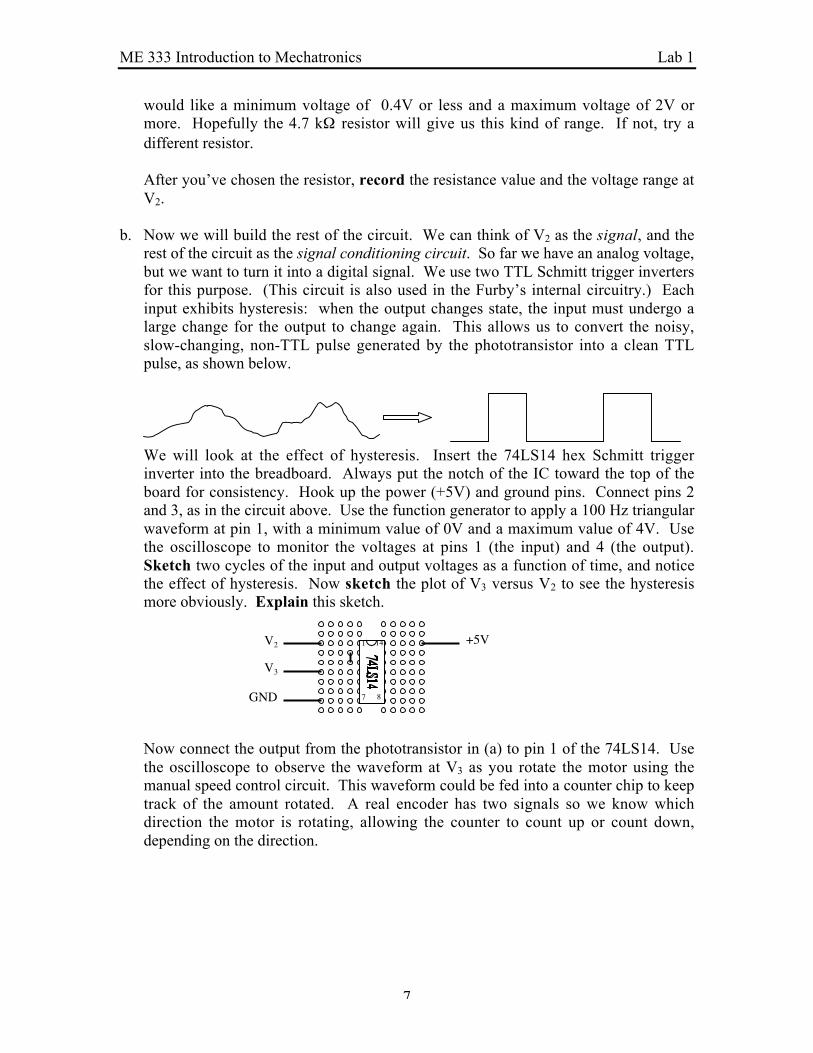
b. Now we will build the rest of the circuit. We can think of V2 as the signal, and therest of the circuit as the signal conditioning circuit. So far we have an analog voltage,but we want to turn it into a digital signal. We use two TTL Schmitt trigger invertersfor this purpose. (This circuit is also used in the Furby’s internal circuitry.) Eachinput exhibits hysteresis: when the output changes state, the input must undergo alarge change for the output to change again. This allows us to convert the noisy,slow-changing, non-TTL pulse generated by the phototransistor into a clean TTLpulse, as shown below.
We will look at the effect of hysteresis. Insert the 74LS14 hex Schmitt triggerinverter into the breadboard. Always put the notch of the IC toward the top of theboard for consistency. Hook up the power (+5V) and ground pins. Connect pins 2and 3, as in the circuit above. Use the function generator to apply a 100 Hz triangularwaveform at pin 1, with a minimum value of 0V and a maximum value of 4V. Usethe oscilloscope to monitor the voltages at pins 1 (the input) and 4 (the output).Sketch two cycles of the input and output voltages as a function of time, and noticethe effect of hysteresis. Now sketch the plot of V3 versus V2 to see the hysteresismore obviously. Explain this sketch.
Now connect the output from the phototransistor in (a) to pin 1 of the 74LS14. Usethe oscilloscope to observe the waveform at V3 as you rotate the motor using themanual speed control circuit. This waveform could be fed into a counter chip to keeptrack of the amount rotated. A real encoder has two signals so we know whichdirection the motor is rotating, allowing the counter to count up or count down,depending on the direction.
V2
V3
+5V
GND
1
7 8
14

ME 333 Introduction to Mechatronics Lab 1
8
6 Workstation Checkoff
Tasks
a. Return all tools to their original location and make sure all equipment is turned off,except for the computer. Do this after each time you use your workstation.
Summary
o Decoupling signal and power circuits, signal loadingo Power dissipationo Current amplificationo Signal conditioning

ME 333 Introduction to Mechatronics Lab 1
9
LAB 1 ANSWERS1 Introduction
2 The Furby
a. Label the parts of the Furby with the correct number.
3 The Manual Speed Control Circuit
a. Total pot resistance (give units): ________
b. R = _______ Chosen resistor: _______
c. Measured voltage range: _______________
d. Calculated current: _____________

ME 333 Introduction to Mechatronics Lab 1
10
e. Calculated voltage range: ___________ Measured voltage range: _____________
f. Maximum dissipated power: ____________
g. Power dissipated by the speed control circuit: _____________
4 The Current Amplifier
a. Vin range: ___________________Explanation:
b. Deadband: ___________________
c. Vin range: ___________________ Vout range: ___________________
d. Max motor current: __________
e. Power dissipated by transistor: __________
f. Transistor gain: _________
5 The Encoder Signal
a. Resistor used: __________ Voltage range at V2: _________
b. Attach sketches of (1) V2 and V3 as a function of time over two cycles, and (2) V3 as afunction of V2. Explain this second sketch.

ME 333 Introduction to Mechatronics Lab 1
11
GND +5V +12V -12V
Furby cable
Green, encoderYellow, homeWhite, motor +Red, +5V encoderBlack, home GNDBlack, motor -
The breadboard at the end of part 2 of Lab 1.

ME 333 Introduction to Mechatronics Lab 1
12
GND +5V +12V -12V
BCE
BCE
Furby cable
Green, encoderYellow, homeWhite, motor +Red, +5V encoderBlack, home GNDBlack, motor -
Red Black+5V GND
Furby power
The final circuit.