Embed Size (px)
Citation preview
Lab Report
Don’t forget: this is one of the 3 labs that requires a formal lab report!
Lab 2Fabula Brower Fowler Flair
Gima Gallagher Germain Garhart
Loman Henry Quelland Lambert-Brown
Robinson-Tillenburg Reiser Shetty San Miguel
Someshwar Rogers Stillwell Stahl
Abdulkadir Stefany Belenky Whittemore
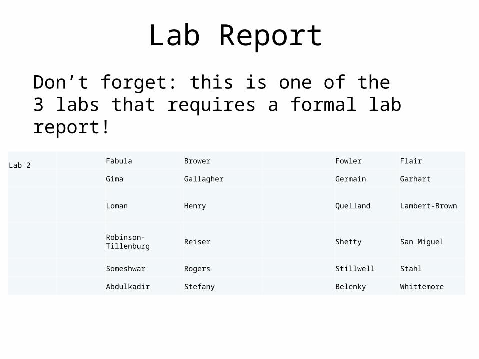
Lab #2: Diode and Rectifier Circuits
• learn what diode is and how it works
• Measure the “turn-on voltage” for some different diode types
• learn what rectification is and how to make a rectifier with diodes
• learn the relationship between AM and rectification
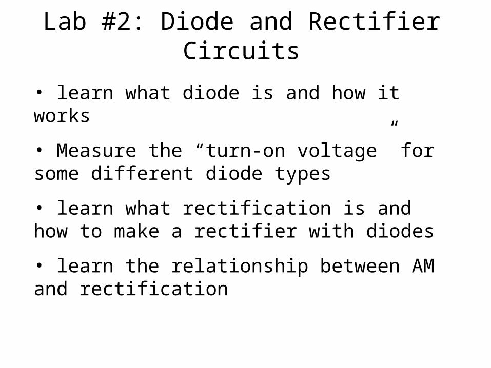
Crystal radio (AM radio)Where is the crystal? No longer in there. Modern crystal radios use diodes instead.
Will start discussion today on purpose of the diode.
Will start discussion today on purpose of the diode.
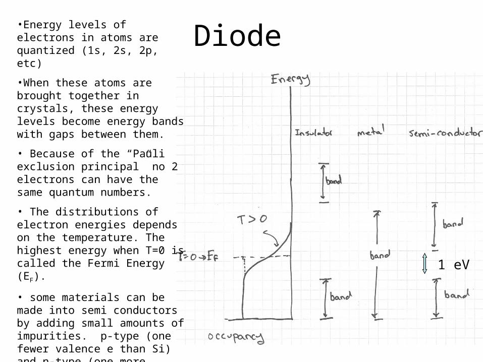
Diode•Energy levels of electrons in atoms are quantized (1s, 2s, 2p, etc)
•When these atoms are brought together in crystals, these energy levels become energy bands with gaps between them.
• Because of the “Pauli exclusion principal” no 2 electrons can have the same quantum numbers.
• The distributions of electron energies depends on the temperature. The highest energy when T=0 is called the Fermi Energy (EF).
• some materials can be made into semi conductors by adding small amounts of impurities. p-type (one fewer valence e than Si) and n-type (one more valence than Si).
• semi conductors do not conduct at T=0.
1 eV
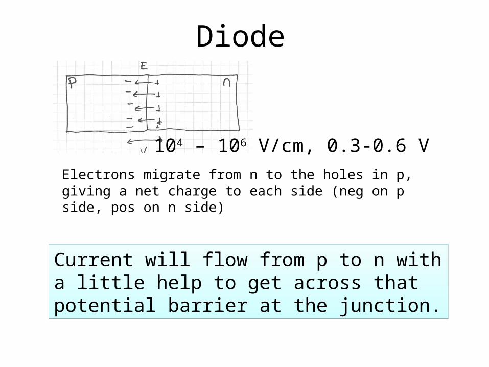
Diode
Electrons migrate from n to the holes in p, giving a net charge to each side (neg on p side, pos on n side)
104 – 106 V/cm, 0.3-0.6 V
Current will flow from p to n with a little help to get across that potential barrier at the junction.
Current will flow from p to n with a little help to get across that potential barrier at the junction.
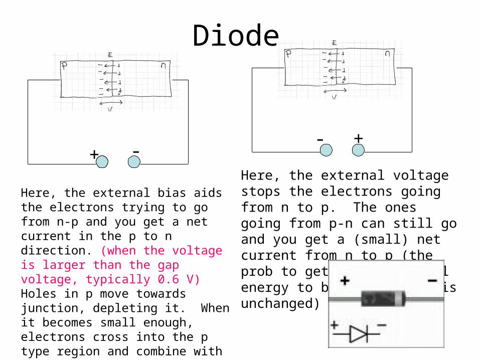
Diode
+ -- +
Here, the external bias aids the electrons trying to go from n-p and you get a net current in the p to n direction. (when the voltage is larger than the gap voltage, typically 0.6 V) Holes in p move towards junction, depleting it. When it becomes small enough, electrons cross into the p type region and combine with holes there. Holes flow in the opposite direction and combine with electrons on the n side. current flows.
Here, the external voltage stops the electrons going from n to p. The ones going from p-n can still go and you get a (small) net current from n to p (the prob to get enough thermal energy to break the bond is unchanged)
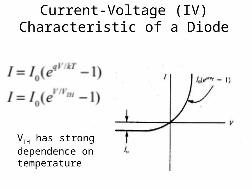
Current-Voltage (IV) Characteristic of a Diode
VTH has strong dependence on temperature
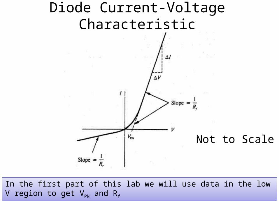
Diode Current-Voltage Characteristic
In the first part of this lab we will use data in the low V region to get VPN and RfIn the first part of this lab we will use data in the low V region to get VPN and Rf
Not to Scale
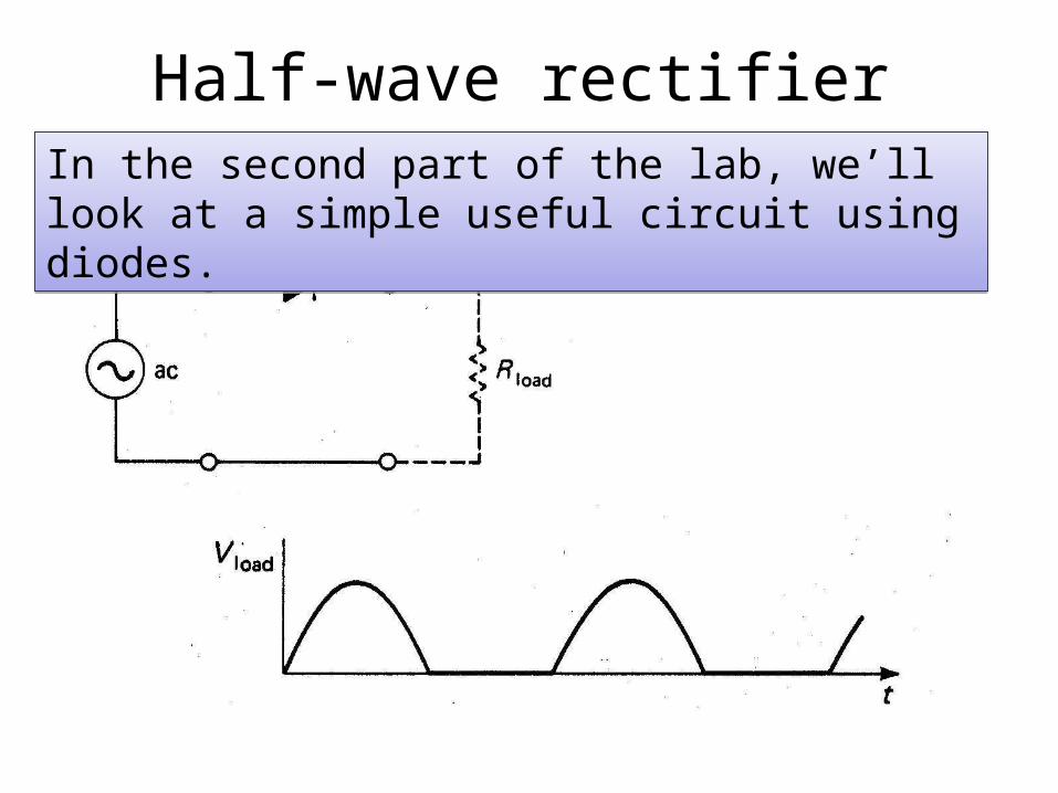
Half-wave rectifierIn the second part of the lab, we’ll look at a simple useful circuit using diodes.In the second part of the lab, we’ll look at a simple useful circuit using diodes.
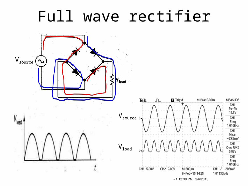
Full wave rectifier
Vsource
Vsource
Vload
New equipment
Instrumentation (differential) amplifier:• Your scope probe, like a volt meter, has two connections. However, for your scope, one of these is hardwired to ground.• If you want to measure the voltage across something, and neither side is at ground, you can:
• Use the AC coupling on the scope• Use the instrumentation amplifier.
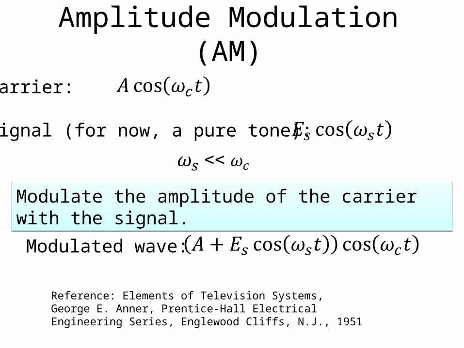
Amplitude Modulation (AM)
Modulate the amplitude of the carrier with the signal.Modulate the amplitude of the carrier with the signal.
Reference: Elements of Television Systems, George E. Anner, Prentice-Hall Electrical Engineering Series, Englewood Cliffs, N.J., 1951
Carrier:
Signal (for now, a pure tone):
Modulated wave:
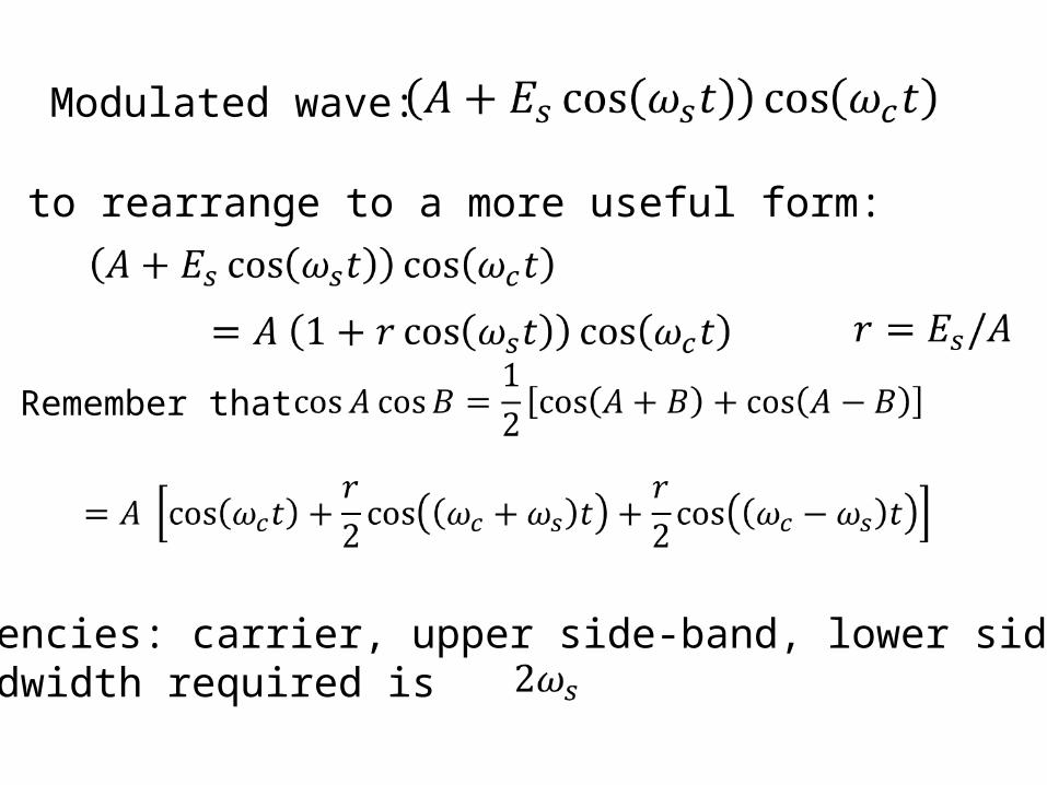
Some math to rearrange to a more useful form:
Modulated wave:
Remember that
3 frequencies: carrier, upper side-band, lower side-bandThe bandwidth required is
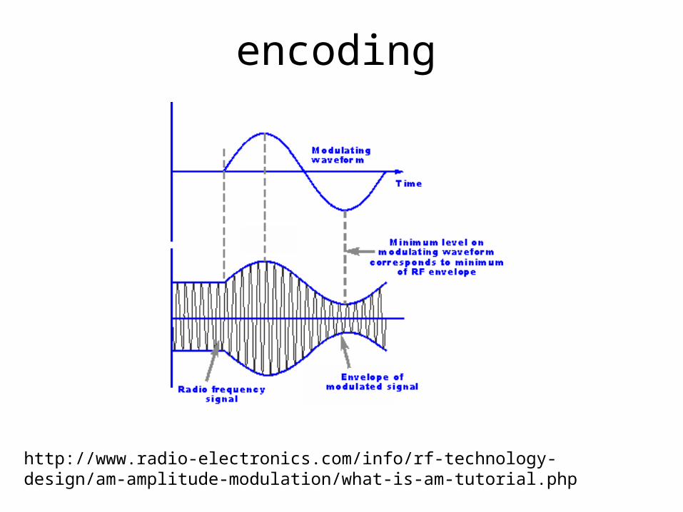
encoding
http://www.radio-electronics.com/info/rf-technology-design/am-amplitude-modulation/what-is-am-tutorial.php
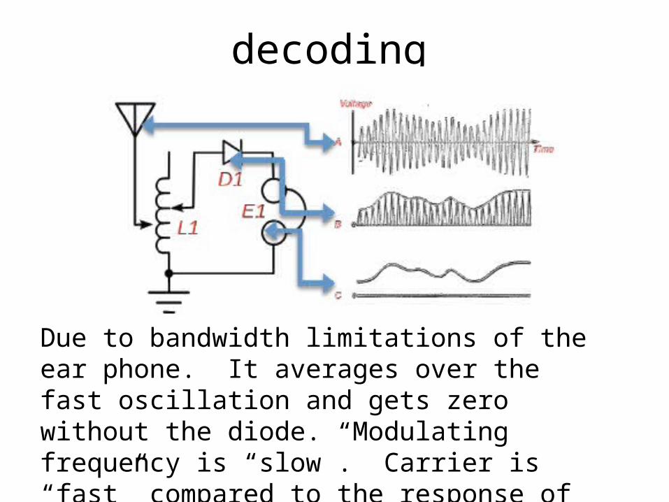
decoding
Due to bandwidth limitations of the ear phone. It averages over the fast oscillation and gets zero without the diode. Modulating frequency is “slow”. Carrier is “fast” compared to the response of the headset.