Embed Size (px)
Citation preview
LABORATORY MODULES
ELECTRICAL MEASUREMENT
ELECTRICAL ENGINEERING DEPARTMENT
FACULTY OF ENGINEERING
UNIVERSITAS INDONESIA
2018
HIGH VOLTAGE AND ELECTRICAL MEASUREMENT LABORATORY
ELECTRICALMEASUREMENTLABORATORYMODULES2018
HighVoltage&ElectricalMeasurementLab.
2
MODULE 1
LABORATORY BRIEFING AND PRE-TEST
Laboratory Breifing is held on February 19, 2018 at 18.45 PM located at K building,
K301, Faculty of Engineering. Attendance to briefing and pre-test is mandatory and will be
included in the scoring system.
ELECTRICALMEASUREMENTLABORATORYMODULES2018
HighVoltage&ElectricalMeasurementLab.
3
MODULE 2
IMPEDANCE MEASUREMENT
I. OBJECTIVE
1. To know LCR Meter and its function
2. To know the construction of LCR Meter and how LCR Meter works
II. BASIC THEORY
LCR meter is an electronic electrical measurement to measure resistance,
inductance and capacitance value. The utilization is relatively easy since today, a digital
LCR meter is already in the market, and it makes the user easier to use it. Here is a brief
explanation about resistor, inductor and capacitor
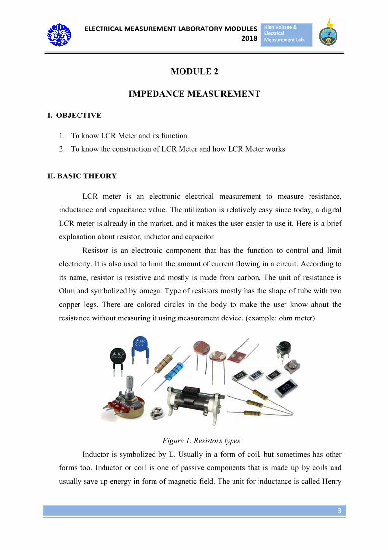
Resistor is an electronic component that has the function to control and limit
electricity. It is also used to limit the amount of current flowing in a circuit. According to
its name, resistor is resistive and mostly is made from carbon. The unit of resistance is
Ohm and symbolized by omega. Type of resistors mostly has the shape of tube with two
copper legs. There are colored circles in the body to make the user know about the
resistance without measuring it using measurement device. (example: ohm meter)
Figure 1. Resistors types
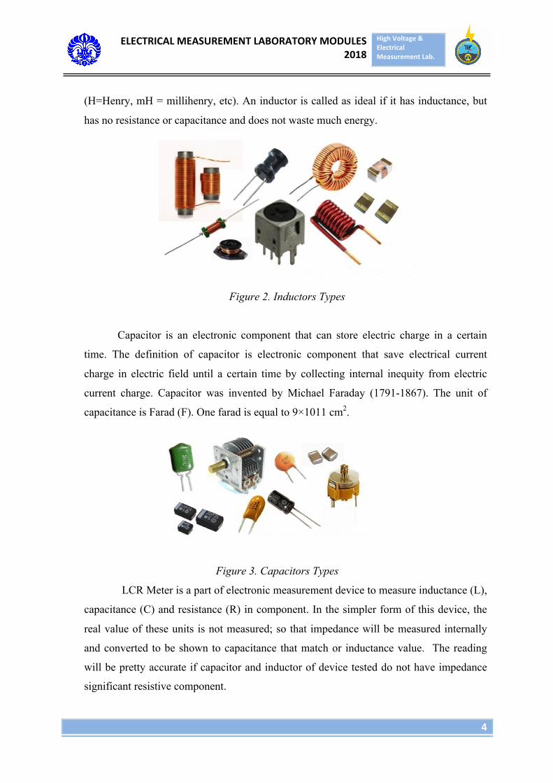
Inductor is symbolized by L. Usually in a form of coil, but sometimes has other
forms too. Inductor or coil is one of passive components that is made up by coils and
usually save up energy in form of magnetic field. The unit for inductance is called Henry
ELECTRICALMEASUREMENTLABORATORYMODULES2018
HighVoltage&ElectricalMeasurementLab.
4
(H=Henry, mH = millihenry, etc). An inductor is called as ideal if it has inductance, but
has no resistance or capacitance and does not waste much energy.
Figure 2. Inductors Types
Capacitor is an electronic component that can store electric charge in a certain
time. The definition of capacitor is electronic component that save electrical current
charge in electric field until a certain time by collecting internal inequity from electric
current charge. Capacitor was invented by Michael Faraday (1791-1867). The unit of
capacitance is Farad (F). One farad is equal to 9×1011 cm2.
Figure 3. Capacitors Types
LCR Meter is a part of electronic measurement device to measure inductance (L),
capacitance (C) and resistance (R) in component. In the simpler form of this device, the
real value of these units is not measured; so that impedance will be measured internally
and converted to be shown to capacitance that match or inductance value. The reading
will be pretty accurate if capacitor and inductor of device tested do not have impedance
significant resistive component.
ELECTRICALMEASUREMENTLABORATORYMODULES2018
HighVoltage&ElectricalMeasurementLab.
5
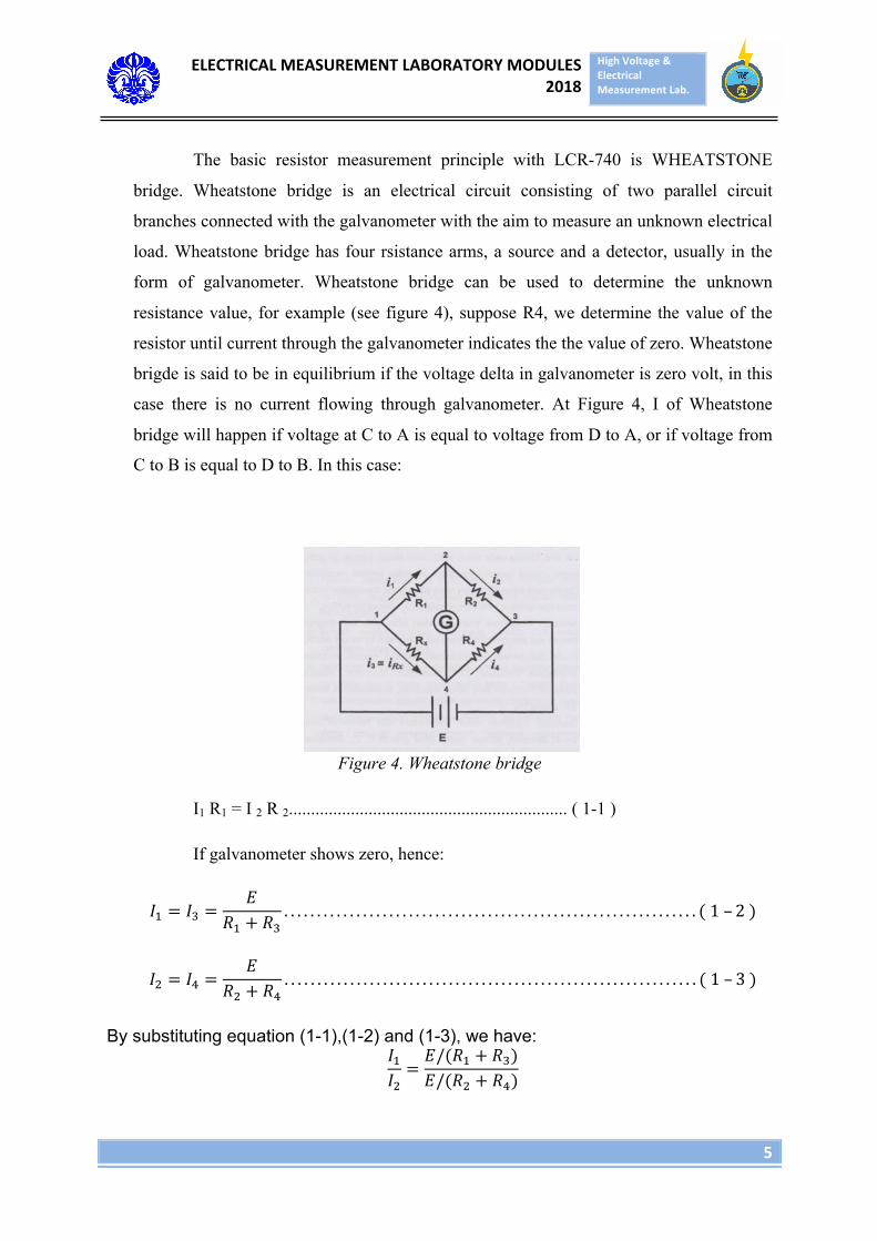
The basic resistor measurement principle with LCR-740 is WHEATSTONE
bridge. Wheatstone bridge is an electrical circuit consisting of two parallel circuit
branches connected with the galvanometer with the aim to measure an unknown electrical
load. Wheatstone bridge has four rsistance arms, a source and a detector, usually in the
form of galvanometer. Wheatstone bridge can be used to determine the unknown
resistance value, for example (see figure 4), suppose R4, we determine the value of the
resistor until current through the galvanometer indicates the the value of zero. Wheatstone
brigde is said to be in equilibrium if the voltage delta in galvanometer is zero volt, in this
case there is no current flowing through galvanometer. At Figure 4, I of Wheatstone
bridge will happen if voltage at C to A is equal to voltage from D to A, or if voltage from
C to B is equal to D to B. In this case:
Figure 4. Wheatstone bridge
I1 R1 = I 2 R 2............................................................... ( 1-1 )
If galvanometer shows zero, hence:
𝐼! = 𝐼! =𝐸
𝑅! + 𝑅!. . . . . . . . . . . . . . . . . . . . . . . . . . . . . . . . . . . . . . . . . . . . . . . . . . . . . . . . . . . . . . . ( 1 – 2 )
𝐼! = 𝐼! =𝐸
𝑅! + 𝑅!. . . . . . . . . . . . . . . . . . . . . . . . . . . . . . . . . . . . . . . . . . . . . . . . . . . . . . . . . . . . . . . ( 1 – 3 )
By substituting equation (1-1),(1-2) and (1-3), we have: 𝐼!𝐼!=𝐸/(𝑅! + 𝑅!)𝐸/(𝑅! + 𝑅!)
ELECTRICALMEASUREMENTLABORATORYMODULES2018
HighVoltage&ElectricalMeasurementLab.
6
𝐼!𝐼!=𝑅! + 𝑅!𝑅! + 𝑅!
𝐼!(𝑅! + 𝑅!) = 𝐼!(𝑅! + 𝑅!)
If I2 from equation (1-1) is inserted, we got:
𝐼! 𝑅! + 𝑅! = 𝐼!𝑅!𝑅!
∗ (𝑅! + 𝑅!)
𝐼!𝑅! + 𝐼!𝑅! = 𝐼!𝑅! + 𝐼! 𝑅!𝑅!𝑅!
𝐼!𝑅!𝑅! = 𝐼!𝑅!𝑅!
𝑅!𝑅! = 𝑅!𝑅!. . . . . . . . . . . . . . . . . . . . . . ( 1 – 4)
Equation 1-4 is a form of Wheatstone bridge equality. If three of the resistances are known
and one of resistance is unknown, for example R4= Rx, hence:
𝑅! = 𝑅!𝑅!𝑅!
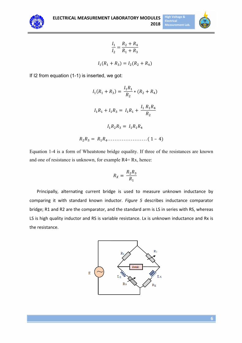
Principally, alternating current bridge is used to measure unknown inductance by
comparing it with standard known inductor. Figure 5 describes inductance comparator
bridge;R1andR2arethecomparator,andthestandardarmisLSinserieswithRS,whereas
LSishighqualityinductorandRSisvariableresistance.LxisunknowninductanceandRxis
theresistance.
ELECTRICALMEASUREMENTLABORATORYMODULES2018
HighVoltage&ElectricalMeasurementLab.
7
Figure 5 InductanceComparatorBridge
If the arm of the bridge is stated in complex form, therefore:
𝑍! = 𝑅! 𝑍! = 𝑅! + 𝐽𝑤𝐿!
𝑍! = 𝑅! 𝑍! = 𝑅! + 𝐽𝑤𝐿!
In equality:
𝑍! ∗ 𝑍! = 𝑍! ∗ 𝑍!
𝑅!(𝑅! + 𝐽𝑤𝐿!) = 𝑅!(𝑅! + 𝐽𝑤𝐿!)
𝑅!𝑅! + 𝑅!𝐽𝑤𝐿! = 𝑅!𝑅! + 𝑅!𝐽𝑤𝐿! …………… (1 – 5)
Two complex numbers are the same, if its real and imaginary are the same. By equating real
part of equation (1-5), hence:
𝑅!𝑅! = 𝑅!𝑅!
𝑅! = 𝑅!𝑅!
𝑅!
For the imaginary,
𝑅!𝐽𝑤𝐿! = 𝑅!𝐽𝑤𝐿!
𝐿! = 𝑅!𝑅!
𝐿!
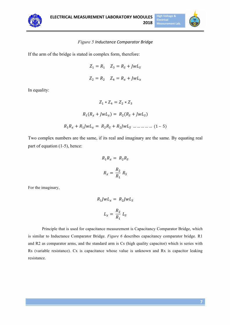
Principle that is used for capacitance measurement is Capacitancy Comparator Bridge, which
is similar to Inductance Comparator Bridge. Figure 6 describes capacitancy comparator bridge. R1
and R2 as comparator arms, and the standard arm is Cs (high quality capacitor) which is series with
Rs (variable resistance). Cx is capacitance whose value is unknown and Rx is capacitor leaking
resistance.
ELECTRICALMEASUREMENTLABORATORYMODULES2018
HighVoltage&ElectricalMeasurementLab.
8
Figure 6. CapacitanceComparatorBridge.
If the arms of inductance comparator bridge are stated in complex form, therefore:
𝑍! = 𝑅! 𝑍! = 𝑅! − 𝐽/𝑤𝐶!
𝑍! = 𝑅! 𝑍! = 𝑅! + 𝐽/𝑤𝐶!
In equilibrium, hence:
𝑍! ∗ 𝑍! = 𝑍! ∗ 𝑍!
𝑅!(𝑅! −𝐽𝑤𝐶!
) = 𝑅!(𝑅! − 𝐽/𝑤𝐶!)
𝑅!𝑅! − 𝑅!𝐽𝑤𝐶!
= 𝑅!𝑅! − 𝑅!𝐽/𝑤𝐶! …………… (1 – 6)
The same with inductance comparator bridge, two complex number is the same if its real and
imaginary are the same. By equating the real part of above’s equation, we have:
𝑅!𝑅! = 𝑅!𝑅!
𝑅! = 𝑅!𝑅!
𝑅!
Hence, the imaginary is:
𝑅!𝐽/𝑤𝐶! = 𝑅!𝐽/𝑤𝐶!
𝐶! = 𝑅!𝑅!
𝐶!
ELECTRICALMEASUREMENTLABORATORYMODULES2018
HighVoltage&ElectricalMeasurementLab.
9
Equalibirum is obtained by controlling the value of variable load, and variation of load R2
and R1 to obtain minimum current flow in the galvanometer. After that the current that flows
thorugh Galvanometer is reduced by varying variable load Rs and keeping R2 and R4
constant. And then keep load Rs constant and change load R2 and R4, repeat the process
above until the bridge is in equalibirum. After reaching equalibirum, capacitance can be
obtained from the equation above.
If the bridge circuit is not ini equalibirum, then the current that flows to the
galvanometer causes a deviation of the galvanometer needle. The maginitude of the deviation
is a function of the galvanometer’s sensitivity. Hence, the sensitivity is calculated as current
per unit(ampere). The galvanometer needle deviation can be expressed linearly or the angle
per unit. The sensitivity S can be stated as
S = millimeters
µ𝐴 atau derajatµ𝐴 𝑎𝑡𝑎𝑢
radianµ𝐴
Thus the total deviation D is :
D = 𝑆 ×𝐼
The thevenin theorem is regularly used to find the current value that flows in the
Galvanometer hence the following equation is obtained :
I! = 𝑉!!
𝑅!! + 𝑅!
III. EXPERIMENT EQUIPMENT
1. LCR Meter
2. Variable Resistor
3. Variable Inductor
4. Variable Capacitor
ELECTRICALMEASUREMENTLABORATORYMODULES2018
HighVoltage&ElectricalMeasurementLab.
10
IV. EXPERIMENT PROCEDURE
1. Prepare all the equipment that will be utilized.
2. Prepare the components that will be measured.
3. Count manually the value of the components.
4. Then measure the components using RLC Meter.
5. Note the result of measurement.
6. Count total impedance of each load.
7. Find the power factor value from load impedance that is measured on LCR Meter and
power factor of load impedance that is stated on the load variable.
8. Compare power factor value of load that is measured by LCR Meter and load that is
stated on the load variable.
ELECTRICALMEASUREMENTLABORATORYMODULES2018
HighVoltage&ElectricalMeasurementLab.
11
MODULE 3
SINGLE PHASE POWER MEASUREMENT
I. OBJECTIVE
1. To know and understand the characteristic of power and power factor measurement
on alternating current circuit with different type of loads.
2. To know the working principle of single phase wattmeter, cos phi meter, amperemeter
and voltmeter.
3. To understand the variation of power type in alternating current system circuitry.
4. To know the usage of power of light bulb, and compare it with the value of power in
its packaging box.
II. BASIC THEORY
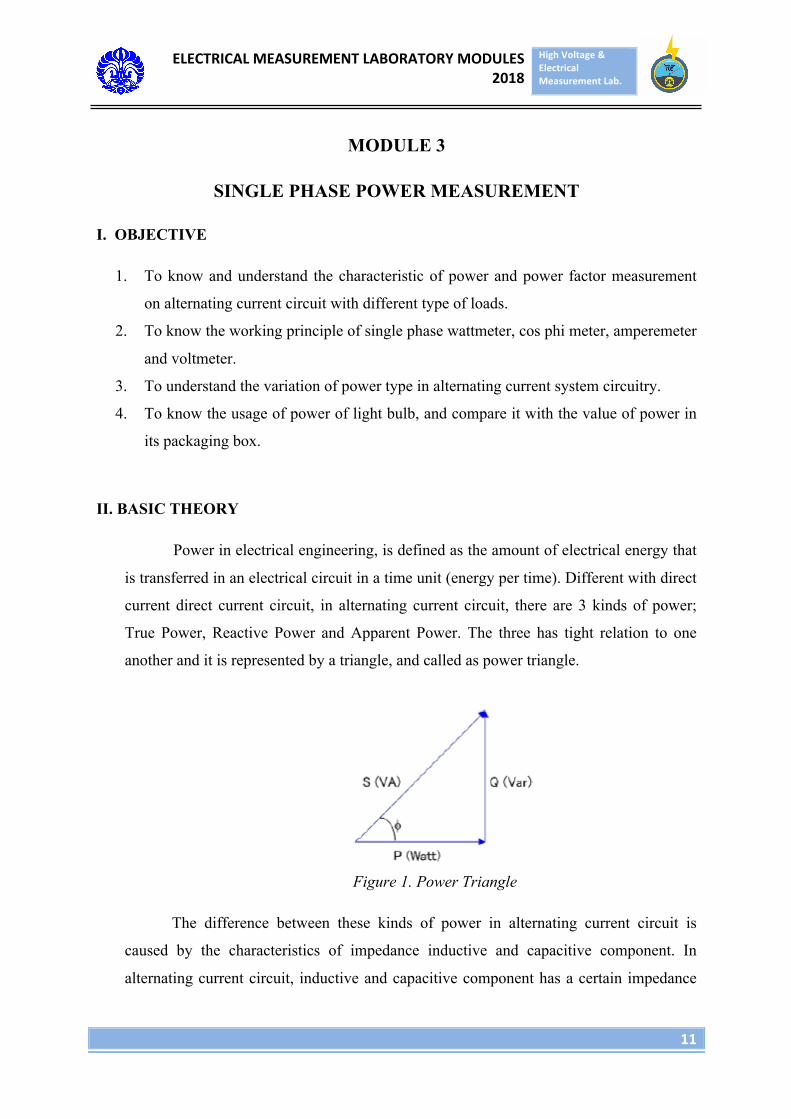
Power in electrical engineering, is defined as the amount of electrical energy that
is transferred in an electrical circuit in a time unit (energy per time). Different with direct
current direct current circuit, in alternating current circuit, there are 3 kinds of power;
True Power, Reactive Power and Apparent Power. The three has tight relation to one
another and it is represented by a triangle, and called as power triangle.
Figure 1. Power Triangle
The difference between these kinds of power in alternating current circuit is
caused by the characteristics of impedance inductive and capacitive component. In
alternating current circuit, inductive and capacitive component has a certain impedance
ELECTRICALMEASUREMENTLABORATORYMODULES2018
HighVoltage&ElectricalMeasurementLab.
12
value due to frequency. These inductive and capacitive components create lagging and
leading of current with respect to voltage, which will affect the multiplication between
voltage and current, and as a result, there are three kinds of power in AC circuitry.
The shape of power triangle is determined by the type of loads in the circuit;
whether it is resistive, inductive, capacitive or combined. The resultant of these loads is
called by impedance, and impedance has the combined characteristics based on which
components composing it. The characteristic of load means the type of power that is
absorbed, and the leading or lagging of the current with respect to voltage. The usage of
inductive /capacitive load will affect the current position with respect to the voltage,
which usually the difference is symbolized by phi, and the amount of cos phi is called as
power factor. Power factor is the ratio between active power and apparent power.
Hence, considering the angle shifting between current and voltage, power can be
stated as
S = V x I*= P + Jq
With:
S à in Volt-Ampere, apparent power
P à in Watt, active power
Q à in VAR, reactive power
V à in Volt, voltage
I* à in Ampere, current
Notice in I, there is a star symbol (*). This symbol states that the value of current
utilized is conjugated mathematically. This equation also states that angle that is formed
by voltage and current is the subtraction between angle that is formed by voltage and
angle that is formed by current. Here is the illustration:
ELECTRICALMEASUREMENTLABORATORYMODULES2018
HighVoltage&ElectricalMeasurementLab.
13
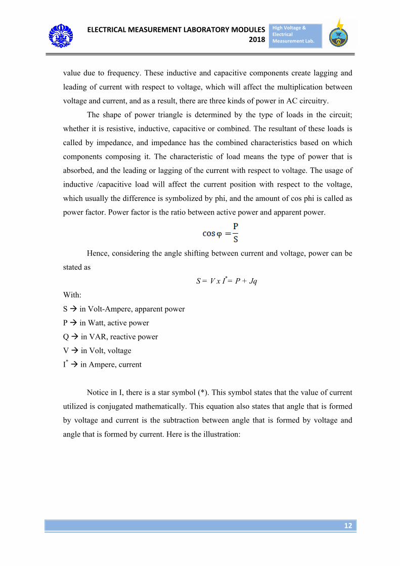
Figure 2. Relationship between voltage and current angles.
With :
α = θ1 – θ2
S = V x I* = V⦟ θ1 x I ⦟- θ2
S =V x I ⦟θ1 – θ2
In this experiment, analog measurement device will be utilized to measure current,
voltage, power and power factor. Analog measurement device mainly has similarities in
having firm and rotating coil that has been calibrated so the movement of its hand
matches with the amount that being read. There are some construction types of analog
measurement device, for example:
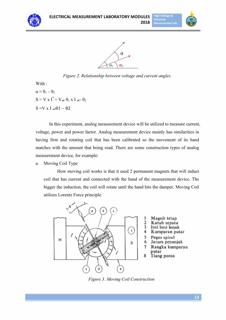
a. Moving Coil Type
How moving coil works is that it used 2 permanent magnets that will induct
coil that has current and connected with the hand of the measurement device. The
bigger the induction, the coil will rotate until the hand hits the damper. Moving Coil
utilizes Lorentz Force principle.
Figure 3. Moving Coil Construction
ELECTRICALMEASUREMENTLABORATORYMODULES2018
HighVoltage&ElectricalMeasurementLab.
14
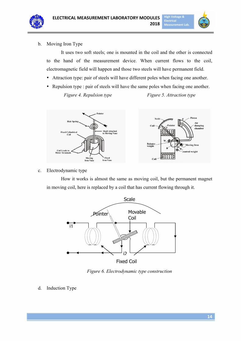
b. Moving Iron Type
It uses two soft steels; one is mounted in the coil and the other is connected
to the hand of the measurement device. When current flows to the coil,
electromagnetic field will happen and those two steels will have permanent field.
• Attraction type: pair of steels will have different poles when facing one another.
• Repulsion type : pair of steels will have the same poles when facing one another.
Figure 4. Repulsion type Figure 5. Attraction type
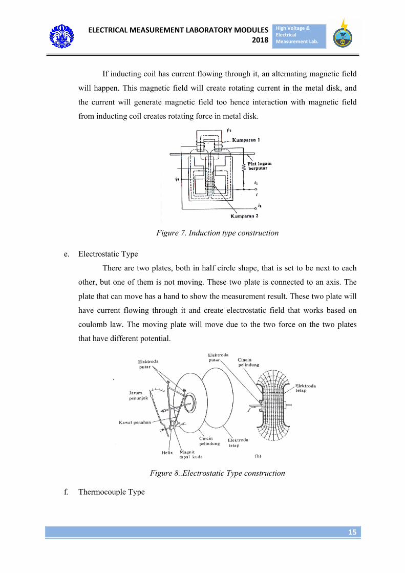
c. Electrodynamic type
How it works is almost the same as moving coil, but the permanent magnet
in moving coil, here is replaced by a coil that has current flowing through it.
Figure 6. Electrodynamic type construction
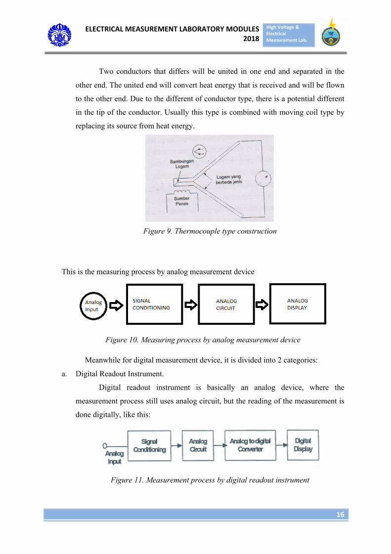
d. Induction Type
i1
i2
Pointer Movable Coil
Scale
Fixed Coil
ELECTRICALMEASUREMENTLABORATORYMODULES2018
HighVoltage&ElectricalMeasurementLab.
15
If inducting coil has current flowing through it, an alternating magnetic field
will happen. This magnetic field will create rotating current in the metal disk, and
the current will generate magnetic field too hence interaction with magnetic field
from inducting coil creates rotating force in metal disk.
Figure 7. Induction type construction
e. Electrostatic Type
There are two plates, both in half circle shape, that is set to be next to each
other, but one of them is not moving. These two plate is connected to an axis. The
plate that can move has a hand to show the measurement result. These two plate will
have current flowing through it and create electrostatic field that works based on
coulomb law. The moving plate will move due to the two force on the two plates
that have different potential.
Figure 8..Electrostatic Type construction
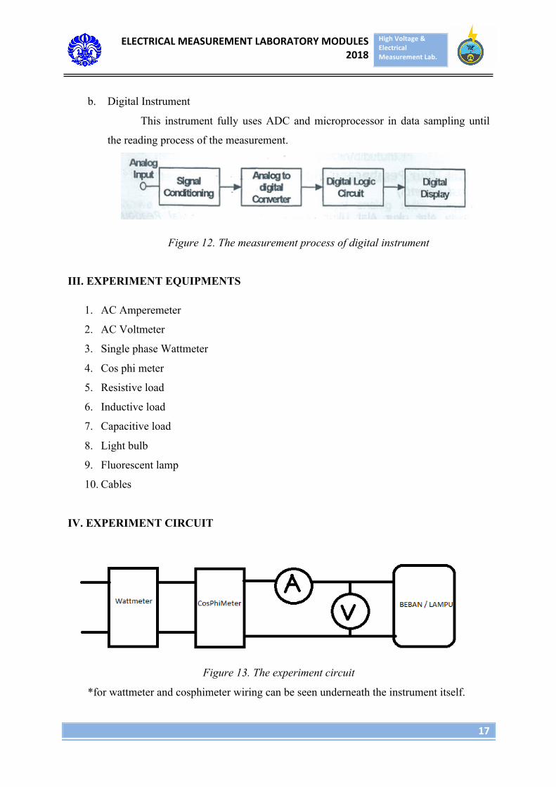
f. Thermocouple Type
ELECTRICALMEASUREMENTLABORATORYMODULES2018
HighVoltage&ElectricalMeasurementLab.
16
Two conductors that differs will be united in one end and separated in the
other end. The united end will convert heat energy that is received and will be flown
to the other end. Due to the different of conductor type, there is a potential different
in the tip of the conductor. Usually this type is combined with moving coil type by
replacing its source from heat energy.
Figure 9. Thermocouple type construction
This is the measuring process by analog measurement device
Figure 10. Measuring process by analog measurement device
Meanwhile for digital measurement device, it is divided into 2 categories:
a. Digital Readout Instrument.
Digital readout instrument is basically an analog device, where the
measurement process still uses analog circuit, but the reading of the measurement is
done digitally, like this:
Figure 11. Measurement process by digital readout instrument
ELECTRICALMEASUREMENTLABORATORYMODULES2018
HighVoltage&ElectricalMeasurementLab.
17
b. Digital Instrument
This instrument fully uses ADC and microprocessor in data sampling until
the reading process of the measurement.
Figure 12. The measurement process of digital instrument
III. EXPERIMENT EQUIPMENTS
1. AC Amperemeter
2. AC Voltmeter
3. Single phase Wattmeter
4. Cos phi meter
5. Resistive load
6. Inductive load
7. Capacitive load
8. Light bulb
9. Fluorescent lamp
10. Cables
IV. EXPERIMENT CIRCUIT
Figure 13. The experiment circuit
*for wattmeter and cosphimeter wiring can be seen underneath the instrument itself.
ELECTRICALMEASUREMENTLABORATORYMODULES2018
HighVoltage&ElectricalMeasurementLab.
18
V. EXPERIMENT PROCEDURES
A. Measuring power and power factor from different types of loads
1. Setting the experiment circuit as written in figure 13
2. Setting up the wattmeter and cos phi meter based on the guideline in the
instrument.
3. Setting up the load combinations
4. Turning on the source
5. Measuring and reading the measurement of voltmeter, amperemeter, cos phi
meter, and wattmeter
6. Repeating steps 3 to 6 with different types of loads.
B. Measuring power of light bulb and fluorescent lamp
1. Setting the experiment circuit as written in figure 13
2. Setting up the wattmeter and cos phi meter based on the guideline in the
instrument.
3. Replacing the load by light bulb
4. Turning on the source
5. Measuring and reading the measurement of voltmeter, amperemeter, cos phi
meter, and wattmeter
6. Comparing the result with the power that is stated in the lamp’s packaging box.
7. Repeating steps 3 to 6 with fluorescent lamp.
ELECTRICALMEASUREMENTLABORATORYMODULES2018
HighVoltage&ElectricalMeasurementLab.
19
MODULE 4
POWER QUALITY AND THREE PHASE POWER MEASUREMENT
I. OBJECTIVES
1. Understanding the definition of power quality
2. Understanding types of disturbance in power quality
3. Understanding the three phase power measurement using 1 three phases wattmeter
and 2 single phase wattmeters.
4. Understanding the power factor measurement of RLC load of three phase circuit.
5. Understanding how wattmeter works.
II. BASIC THEORY
Power quality is a condition between electricity source and the supplied electrical
appliances. The power quality describes how good or bad the quality of electricity due to
some disturbances that may happen in electricity system.
Usually what are talked about in power quality is the disturbances that happen.
Generally, the quality of power has three important parameters, which is voltage, current
and frequency. Every deviation from voltage, current and frequency from its normal
condition that can make the quality of power delivered and system performance worse,
and it could create failure of system or the wrong electrical load operation from
consumer side.
Here are the problems of power quality:
a) Voltage Drop, voltage that disspates due to impedance of the circuit
b) Transient, a phenomenon that involves variable change(voltage, current, etc) that
occurs during transition period from steady state to another state, transient is divided
into :
a. Impulse transient : transient that only has one direction of polarity
b. Oscillatory transient : transient that has two directions of polarity
ELECTRICALMEASUREMENTLABORATORYMODULES2018
HighVoltage&ElectricalMeasurementLab.
20
c) Gejala Perubahan Tegangan Durasi Pendek (Short-Duration Variation) Short
Duration Variations is a voltage value changing phenomenon in short priod of time
which is less than a minute
• Based on the duration of the incident, SDV consist of 3 types, which are :
1. Instantaneous : Voltage change occurs for 0.5 until 30 cycles
2. Momentary : Voltage change occurs for 30 cycles until 3 seconds
3. Temporary : Voltage change occurs for 3 seconds until 1 minute
• Based on the voltage change value, SDV consist of 3 types, which are
1. Interruption : reduction of voltage or electrical current until it is below 0.1
pu for a period of time not exceeding 1 minute
2. Sag : reduction of voltage or electrical current 0.1-0.9 pu in a period of 0.5
cycles - 1 minute
3. Swell : increase of voltage or electrical current on 1.1-1.8 pu in 0.5 -1
minute
d) Long Duration variations is voltage changing phenomenon, in a long time period
which exceed 1 minute, it is divided into 3 types which are sustained interruption,
undervoltages, and overvoltages.
e) Voltage unbalance, a pehomenon where there is a voltage value difference in a three
phase system and also its phase angle
f) Wave distortion, for example is Harmonics which is a deviation phenomenon of a
wave (voltage and current) from its ideal form which is a sinusoidal wave.
g) Flicker : voltage variation caused by fast and continuous load change.
h) Frequency deviation, types :
a. Frequency variation
b. Radio Frequency Interference : disturbance caused by electromagnetic induction
from an external source
c. EMF
The measurement of three phase power measurement use couple of methods:
• Measurement using 1 three phase wattmeter (poly phase)
• Measurement using 2 single phase wattmeter (single phase)
ELECTRICALMEASUREMENTLABORATORYMODULES2018
HighVoltage&ElectricalMeasurementLab.
21
• Measurement using 3 voltmeters and 3 amperemeters
• Measurement using 3 single phase wattmeter (single phase)
• Measurement using 3 V-A meter.
In this experiment, methods being used are 2 single phase wattmeters and 1 three
phase wattmeters.
There are three construction types of wattmeter:
1. Electrodynamic Type
2. Induction Type
3. Thermocouple Typ
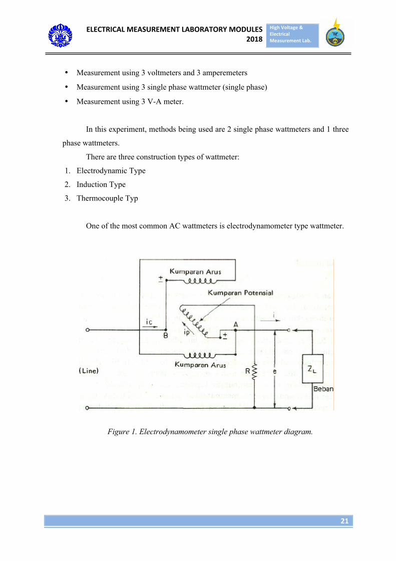
One of the most common AC wattmeters is electrodynamometer type wattmeter.
Figure 1. Electrodynamometer single phase wattmeter diagram.
ELECTRICALMEASUREMENTLABORATORYMODULES2018
HighVoltage&ElectricalMeasurementLab.
22
III. EXPERIMENT EQUIPMENT
1. 1 polyphase wattmeter
2. 2 single phase wattmeters
3. Cos phi meter
4. Resistive load
5. Inductive load
6. Capasitive load
7. Cables
IV. EXPERIMENT CIRCUIT
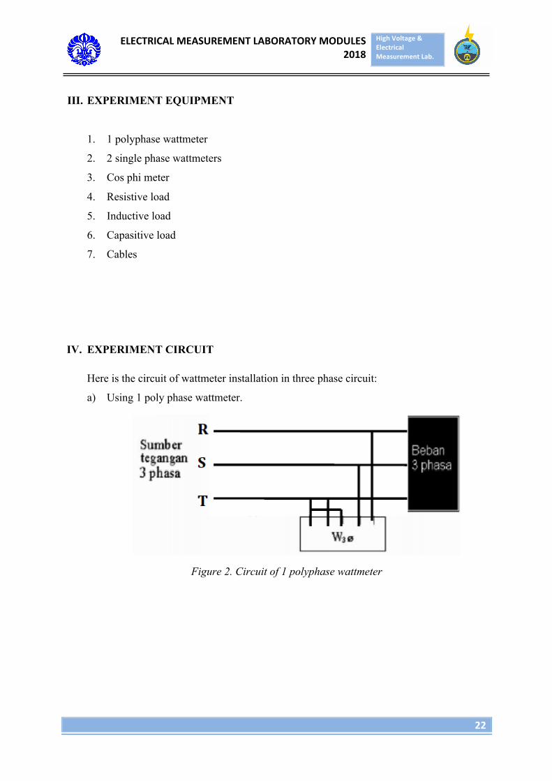
Here is the circuit of wattmeter installation in three phase circuit:
a) Using 1 poly phase wattmeter.
Figure 2. Circuit of 1 polyphase wattmeter
ELECTRICALMEASUREMENTLABORATORYMODULES2018
HighVoltage&ElectricalMeasurementLab.
23
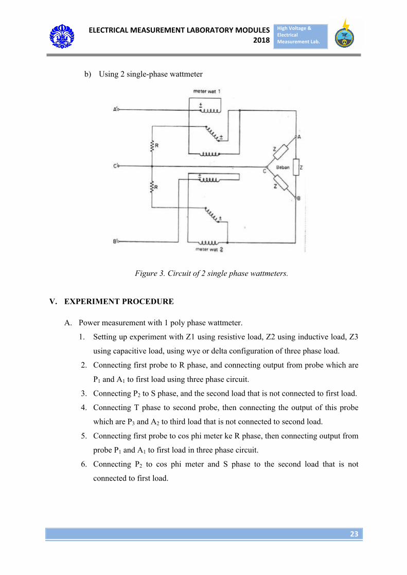
b) Using 2 single-phase wattmeter
Figure 3. Circuit of 2 single phase wattmeters.
V. EXPERIMENT PROCEDURE
A. Power measurement with 1 poly phase wattmeter.
1. Setting up experiment with Z1 using resistive load, Z2 using inductive load, Z3
using capacitive load, using wye or delta configuration of three phase load.
2. Connecting first probe to R phase, and connecting output from probe which are
P1 and A1 to first load using three phase circuit.
3. Connecting P2 to S phase, and the second load that is not connected to first load.
4. Connecting T phase to second probe, then connecting the output of this probe
which are P3 and A2 to third load that is not connected to second load.
5. Connecting first probe to cos phi meter ke R phase, then connecting output from
probe P1 and A1 to first load in three phase circuit.
6. Connecting P2 to cos phi meter and S phase to the second load that is not
connected to first load.
ELECTRICALMEASUREMENTLABORATORYMODULES2018
HighVoltage&ElectricalMeasurementLab.
24
7. Connecting T phase to P3 and third load to three phase circuit that is not
connected to second load.
8. Checking if cable connection installed properly and load had been switched on
before circuit is on.
9. After being turned on, observe and note the value that is read by two wattmeters
and cosphi meter.
B. Power measurement using 2 Single Phase Wattmeter.
1. Construct the circuit with Z1 as resistive load, Z2 as inductive load, and Z3 as
capacitive load, and create wye or delta configuration on three phase loads.
2. Connecting phase source R to the first single phase wattmeter, and from
wattmeter connect it to Z1 load of three phase load configuration.
3. Connecting phase source S directly to Z2 load of three phase load configuration.
4. Connecting phase source T to second single phase wattmeter, and from
wattmeter connects to cosphi meter. Then, connect Z3 load to three phase load.
5. Checking if cable has installed properly and load had been switched on before
the circuit is on.
6. After being turned on, observe and note the value on wattmeters and also cos
phi meter
ELECTRICALMEASUREMENTLABORATORYMODULES2018
HighVoltage&ElectricalMeasurementLab.
25
MODULE 5
LIGHTING MEASUREMENT
I. OBJECTIVE
1. Understanding lighting concept
2. Understanding units in lighting measurement
3. Understanding lighting measurement device
4. Knowing application and usage of lighting measurement.
II. BASIC THEORY
Light is an electromagnetic radiation that can be caught by eyes and has
wavelength from 0.4 x 10⁻⁴ -~ 0.75 x 10⁻⁴ cm. Light also can be defined as the amount of
lighting on a working plane that is needed to do activity effectively. Based on the sources,
lighting is divided into 2 kinds :
a. Natural lighting
Natural lighting is lighting that is based on sun rays.
b. Artificial lighting
Artificial lighting is lighting that is based on any other sources, except sun rays.
Beside its source, a lighting system can be divided into 3 kinds, based on the
distribution :
a. Distributed lighting system
In this system, light illumination is spread evenly with the same strong light intensity
on the entire horizontal surface in the room.
b. Localized lighting system
In this system, light is provided to provide highly selective illumination in a
relatively wide place or field. Usually installed with common lighting, where
localized lighting is used as lighting for work and distributed lighting is used as
basic lighting.
ELECTRICALMEASUREMENTLABORATORYMODULES2018
HighVoltage&ElectricalMeasurementLab.
26
c. Directed lighting system
In this system, light is concentrated from a particular direction to the work plane
within the space/limited area or directed to specific object such as painting.
One of the most common artificial lighting sources that utilized by human is lamp.
Lamps can be categorized into several types, according to the method that is used to emit
light. These lamps also has differences in shapes, power consumption, and also the
heat/brightness. :
a. Light Bulb
Light in light bulb is resulted from tungsten made-filament that shines due
to heat. Only 8-10% of the energy is converted to light; the rest is converted to heat
form. Halogen lamp is included to this group.
Basically, filament in light bulb is a resistor. If an electrical current goes
through it, the filament turns extremely hot, and its temperature will be
approximately 2800 K until 3700 K in its peak. This causes the light color from light
bulb is in yellow redish. In that extremely high temperature, filament will produce
light in a visible wavelength.
b. Fluorescent lamp
The light in this lamp comes from phosphoric powder which covers the
inner part of lamp’s tube. The powder determines the color of the light produced.
More than 25% of energy consumed by this lamp is converted into light.
When a 220 volt of AC voltage is connected to one set of fluorescent lamp,
the voltage of the tip of starter is enough to cause neon gas in starter tube to be
ionized and it will cause the starter from normally open to closed, hence the neon
gas inside will be deionized. In this closed starter condition, a current will flow to
heat filament of fluorescent lamp tube and the gas inside the tube will be ionized.
Once the neon gas in the starter tube is cooled enough, the bimetal in starter tube
will be opened again so the ballast will produce a high voltage spike and causes
electron jump from the two electrodes and shines the fluorescent layer on the lamp’s
tube.
c. HID (High Intensity Discharge) lamp
ELECTRICALMEASUREMENTLABORATORYMODULES2018
HighVoltage&ElectricalMeasurementLab.
27
The light in this lamp is caused by electrical prod using metal vapor.
Mercury lamps and metal halide lamps are some examples of HID lamp.
d. LED (Light-Emmiting Diode) lamp
This lamp is composed by a set of LED to emit light. The LED light will
appear without heating of the components. LED needs DC source to energize it with
low voltages. Due to that reason, a step down transformer circuit is also equipped to
decrease source’s voltage that goes in to the circuit.
In lighting measurement, some specific terms are used, for example:
1. Light intensity
It is the strength of light from a light source. The amount is measured in
candela (cd) unit.
2. Lumen
Lumen (SI unit, symbolized by lm) is a unit for light flux that is emitted in
a solid angle unit by a source with light intensity of 1 candela. One lumen is equal to
the amount of light uniformly emitted of 1 candela in 1 steradian solid angle. It is
written 1 lm= 1 cd sr.
3. Illumination
Illumination or lighting intensity is the amount of light exposing a surface.
Illumination has unit of footcandles (fc) or in lux form; 1 lux= 1 lumen /m2
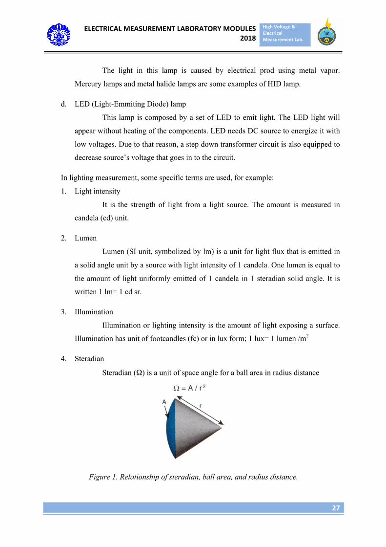
4. Steradian
Steradian (Ω) is a unit of space angle for a ball area in radius distance
Figure 1. Relationship of steradian, ball area, and radius distance.
ELECTRICALMEASUREMENTLABORATORYMODULES2018
HighVoltage&ElectricalMeasurementLab.
28
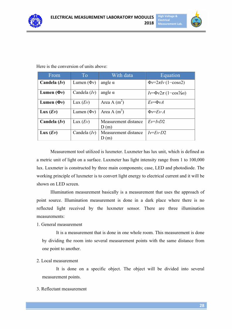
Here is the conversion of units above:
Measurement tool utilized is luxmeter. Luxmeter has lux unit, which is defined as
a metric unit of light on a surface. Luxmeter has light intensity range from 1 to 100,000
lux. Luxmeter is constructed by three main components; case, LED and photodiode. The
working principle of luxmeter is to convert light energy to electrical current and it will be
shown on LED screen.
Illumination measurement basically is a measurement that uses the approach of
point source. Illumination measurement is done in a dark place where there is no
reflected light received by the luxmeter sensor. There are three illumination
measurements:
1. General measurement
It is a measurement that is done in one whole room. This measurement is done
by dividing the room into several measurement points with the same distance from
one point to another.
2. Local measurement
It is done on a specific object. The object will be divided into several
measurement points.
3. Reflectant measurement
From To With data Equation Candela (Iv) Lumen (Φv) angle α Φv=2πIv (1−cosα2)
Lumen (Φv) Candela (Iv) angle α Iv=Φv2π (1−cos½α)
Lumen (Φv) Lux (Ev) Area A (m2) Ev=ΦvA
Lux (Ev) Lumen (Φv) Area A (m2) Φv=Ev⋅A
Candela (Iv) Lux (Ev) Measurement distance D (m)
Ev=IvD2
Lux (Ev) Candela (Iv) Measurement distance D (m)
Iv=Ev⋅D2
ELECTRICALMEASUREMENTLABORATORYMODULES2018
HighVoltage&ElectricalMeasurementLab.
29
It is a measurement of reflectant by doing twice of measurement. First
measurement is to measure lighting intensity on the surface by putting photo cell
facing the light source. The second measurement is by turning over the photocell
facing the surface, and pulling photo cell until the number on display shows highest
number. The amount of reflectant is formulated here:
Reflectant= (Measurement 2/ Measurement 1) x 100%
Lumen measurement is important to save energy in lighting. The application of
lumen measurement can be utilized on these fields:
1. Lighting level measurement on buildings
2. Luminaire light intensity distribution measurement
3. In videography, photography and architecture.
III. EXPERIMENT EQUIPMENT
1. Luxmeter LX-1108
2. 1 Light bulb
3. 4 Fluorescent Lamp
4. 1 LED Lamp
5. AC Power Supply
IV. EXPERIMENT PROCEDURE
A. Voltage variation general measurement
1. Install the lamp in fitting in the middle of the room
2. Turn on the power supply
3. Adjust the power supply in the voltage that desired
4. Make sure the light in the room only comes from that source only.
5. Adjust the luxmeter position under the light with distance 1 meter above the
floor.
6. Make sure the light that is caught by luxmeter sensor is not interfered by
shadow.
ELECTRICALMEASUREMENTLABORATORYMODULES2018
HighVoltage&ElectricalMeasurementLab.
30
7. Turn on the luxmeter, open the sensor cover, and note the value on the luxmeter.
8. Repeat steps 3,4,5,6,7 with different voltage variations.
B. Lamp brand variation general measurement.
1. Install the lamp in the fitting in the middle of the room.
2. Turn on power supply and adjust power supply at 220 V
3. Make sure the light in the room only come from the lamp.
4. The measurement will take place at 12 points that have been decided.
5. Adjust the position of luxmeter at the first point with 1 meter distance above
ground.
6. Make sure the light that caught by luxmeter sensor is not covered by shadow
7. Turn on the luxmeter, open the sensor cover and note the value on the luxmeter.
8. Repeat steps 5,6, and 7 until the 12th point.
9. Repeat steps 1-8 to each different lamp brands.
C. General measurement of lamp type variation
1. Install the lamp in the fitting in the middle of the room.
2. Turn on power supply and adjust power supply at 220 V
3. Make sure the light in the room only come from the lamp.
4. The measurement will take place at 12 points that have been decided.
5. Adjust the position of luxmeter at the first point with 1 meter distance above
ground.
6. Make sure the light that caught by luxmeter sensor is not covered by shadow
7. Turn on the luxmeter, open the sensor cover and note the value on the
luxmeter.
8. Repeat steps 5,6, and 7 until the 12th point.
9. Repeat steps 1-8 to each different lamp type
ELECTRICALMEASUREMENTLABORATORYMODULES2018
HighVoltage&ElectricalMeasurementLab.
31
MODULE 6
GROUNDING RESISTANCE MEASUREMENT
I. OBJECTIVE
1. Knowing the amount of grounding resistance of a place.
2. Knowing and understanding the function and usage of grounding resistance
measurement and its application daily.
3. Knowing the earth ground tester working principle
II. BASIC THEORY
Grounding resistance is a resistance of a grounding system that aims to divert
lightning current to the ground so there will be no loss happened due to grounding current.
The aim of grounding:
a. Safety and security
b. The tunnel for leakage current
c. Protection of device.
In an electrical installation, there are four parts that need to be grounded, they are:
a. Every installation part that is made from conductor (metal) and can be easily
touched by human.
This is necessary so that the potential of those metals will always be the same with
ground potential, where human stands, so it is not going to be dangerous for human
to touch it.
b. The lower part of lightning arrester.
This is necessary so lighting arrester can function well, which is to divert the
electricity from lightning to the ground directly.
c. The lightning rod on the upper part of transmission line.
ELECTRICALMEASUREMENTLABORATORYMODULES2018
HighVoltage&ElectricalMeasurementLab.
32
This rod acts as lightning arrester. Since it is located along the transmission line, all
of the legs of transmission poles has to be grounded so the lightning can be diverted
to the ground via the poles’ legs.
d. Neutral point of transformer or generator.
This relates with the protection necessity.
Lightning happens due to potential difference between cloud and earth or between
cloud and another cloud. If the potential difference between cloud and ground is huge,
there will be an electron disposal from cloud to ground or vice versa, to reach equilibrium.
The mechanism of lightning is started by downward leader. This movement will reach the
ground, so the negative charge brought by downward leader will increase positive charge
induction on ground surface. Then the positive charge in a huge amount will move
upward by upward leader, responding downward leader movement, and a contact from
the two happens, as a lightning.
Grounding system is related to lightning protection. Lightnng protection is dvided
into:
a. Internal protection system
Its objective is to protect objects from indirect lightning flash which is
magnetic field induction. Here are the types of internal protection system:
1. Bonding
2. Surge Protection Devices
3. Shielding
4. Safe Distance
b. External protection system
External protection system is used to protect object from direct lightning flash.
The types are:
1. Dissipation Array System (DAS)
Dissipation Array System enables lightning flash not to happen in a
location. Point discharge that has sharp point is placed in several places of
ELECTRICALMEASUREMENTLABORATORYMODULES2018
HighVoltage&ElectricalMeasurementLab.
33
buildings’ roof, to move electric charge of that object to air. The charge released
by point discharge will decrease the potential difference between ground and
cloud, and reducing the cloud’s ability to release charge to earth.
2. Charge Transfer System (CTS)
Charge Transfer System is the most common external lightning protection.
In this system, lightning will strike but the position of the strike had been
predicted, so it will not strike the other parts. The methods of CTS are:
a. Franklin Rod
b. Faraday Cage
c. Radioactive (Early Streamer Emission Air Terminal)
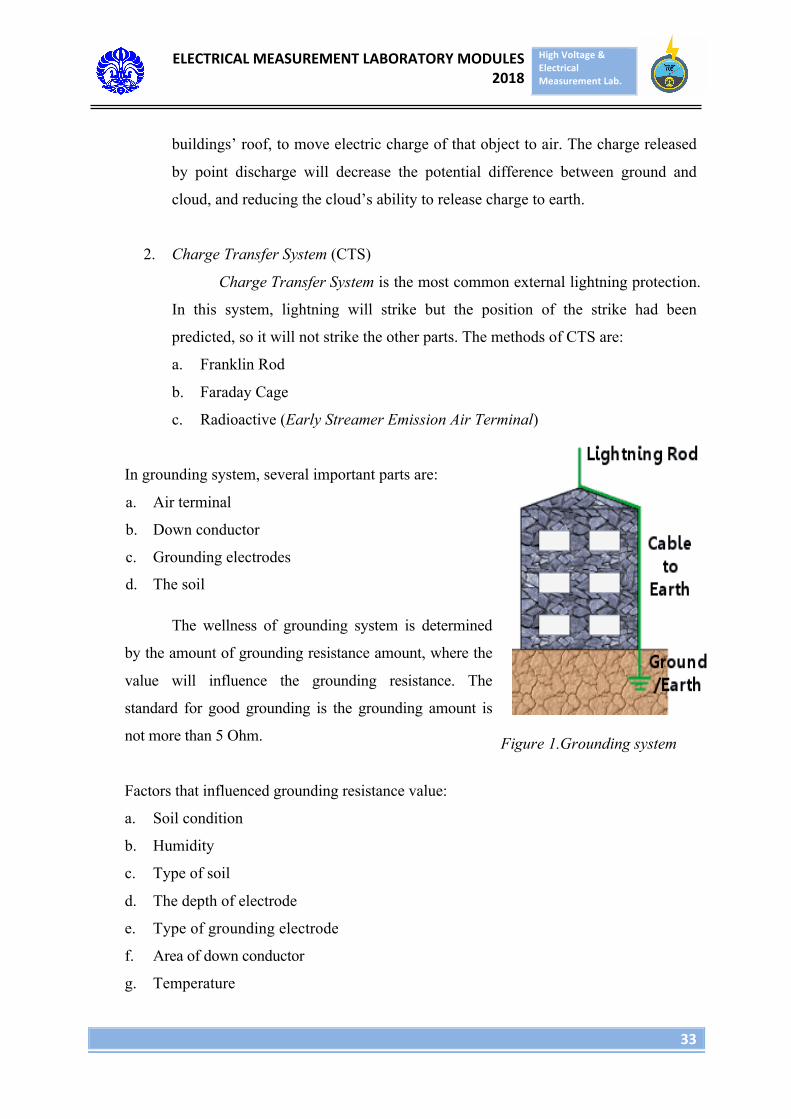
In grounding system, several important parts are:
a. Air terminal
b. Down conductor
c. Grounding electrodes
d. The soil
The wellness of grounding system is determined
by the amount of grounding resistance amount, where the
value will influence the grounding resistance. The
standard for good grounding is the grounding amount is
not more than 5 Ohm.
Factors that influenced grounding resistance value:
a. Soil condition
b. Humidity
c. Type of soil
d. The depth of electrode
e. Type of grounding electrode
f. Area of down conductor
g. Temperature
Figure 1.Grounding system
ELECTRICALMEASUREMENTLABORATORYMODULES2018
HighVoltage&ElectricalMeasurementLab.
34
h. Air terminal type
To reduce the grounding resistance value:
a. Paralelling grounding electrodes
b. Changing the grounding electrode type
c. Creating pool to make the soil humid
d. Adding salt to the ground
e. Increasing the depth of grounding electrodes
There are two methods to measure grounding resistance of a location
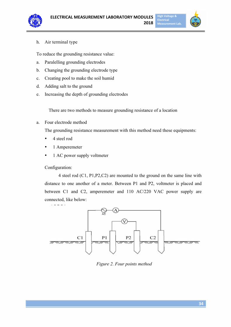
a. Four electrode method
The grounding resistance measurement with this method need these equipments:
• 4 steel rod
• 1 Amperemeter
• 1 AC power supply voltmeter
Configuration:
4 steel rod (C1, P1,P2,C2) are mounted to the ground on the same line with
distance to one another of a meter. Between P1 and P2, voltmeter is placed and
between C1 and C2, amperemeter and 110 AC/220 VAC power supply are
connected, like below:
Figure 2. Four points method
ELECTRICALMEASUREMENTLABORATORYMODULES2018
HighVoltage&ElectricalMeasurementLab.
35
Measurement method:
Connecting power supply, measuring how many amperes of current flowing
between C1 and C2, say I Ampere. Then measuring how many potential difference
between P1 and P2, say V (volt). Insert all of them in:
Rho = 2 π a R
where π = 3,14
a = distance between steel rod
R = V/I
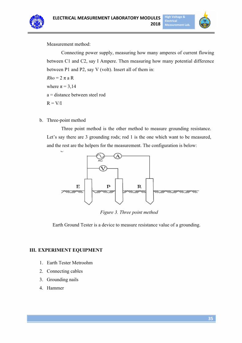
b. Three-point method
Three point method is the other method to measure grounding resistance.
Let’s say there are 3 grounding rods; rod 1 is the one which want to be measured,
and the rest are the helpers for the measurement. The configuration is below:
Figure 3. Three point method
Earth Ground Tester is a device to measure resistance value of a grounding.
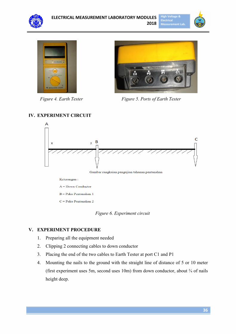
III. EXPERIMENT EQUIPMENT
1. Earth Tester Metroohm
2. Connecting cables
3. Grounding nails
4. Hammer
ELECTRICALMEASUREMENTLABORATORYMODULES2018
HighVoltage&ElectricalMeasurementLab.
36
Figure 4. Earth Tester Figure 5. Ports of Earth Tester
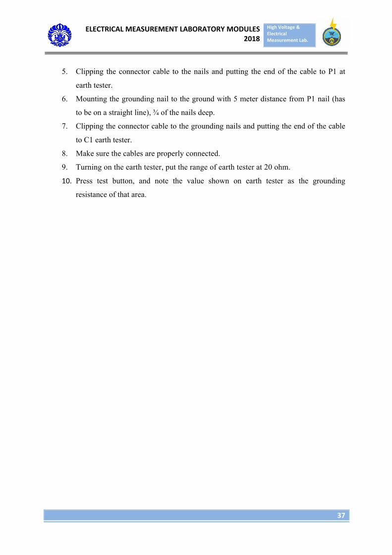
IV. EXPERIMENT CIRCUIT
Figure 6. Experiment circuit
V. EXPERIMENT PROCEDURE
1. Preparing all the equipment needed
2. Clipping 2 connecting cables to down conductor
3. Placing the end of the two cables to Earth Tester at port C1 and P1
4. Mounting the nails to the ground with the straight line of distance of 5 or 10 meter
(first experiment uses 5m, second uses 10m) from down conductor, about ¾ of nails
height deep.
ELECTRICALMEASUREMENTLABORATORYMODULES2018
HighVoltage&ElectricalMeasurementLab.
37
5. Clipping the connector cable to the nails and putting the end of the cable to P1 at
earth tester.
6. Mounting the grounding nail to the ground with 5 meter distance from P1 nail (has
to be on a straight line), ¾ of the nails deep.
7. Clipping the connector cable to the grounding nails and putting the end of the cable
to C1 earth tester.
8. Make sure the cables are properly connected.
9. Turning on the earth tester, put the range of earth tester at 20 ohm.
10. Press test button, and note the value shown on earth tester as the grounding
resistance of that area.
ELECTRICALMEASUREMENTLABORATORYMODULES2018
HighVoltage&ElectricalMeasurementLab.
38
MODULE 7
ENERGY CONSUMPTION MEASUREMENT
I. OBJECTIVE
1. Understanding how kWh meter works.
2. Knowing the difference of analog kWh meter and digital kWh meter.
3. Knowing the advantages and drawbacks of each type of kWh meter.
II. BASIC THEORY
Energy is the amount of power consumed in a certain time. kWh meter is the
tool used to measure the power consumption on a consumer. kWh meter is basically
divided as analog type and digital type:
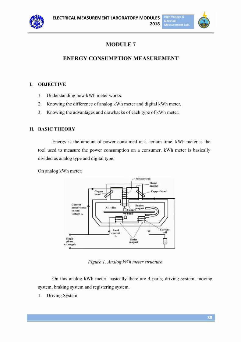
On analog kWh meter:
Figure 1. Analog kWh meter structure
On this analog kWh meter, basically there are 4 parts; driving system, moving
system, braking system and registering system.
1. Driving System
ELECTRICALMEASUREMENTLABORATORYMODULES2018
HighVoltage&ElectricalMeasurementLab.
39
This part is consisted of 2 electromagnets called as shunt magnet and series
magnet. The voltage coil that is connected with supply is put in the center of shunt
magnet. The current coil is in series with load. The coil will carry load’s current and
producing proportional flux with load’s current.
2. Moving System
The moving system in analog kWh meter consists of aluminum plate that is
perpendicular with the rotating axis. The shaft of this plate is connected with the
hand in the front part of kWh meter to show the information of energy consumption.
The aluminum plate is driven by torque coming from magnetic field that is inducted
from eddy current in aluminum plate.
3. Braking System
The braking system in analog kWh meter is controlled by a permanent
magnet that is located across the driving system’s magnet. This permanent magnet
will create magnetic field that opposes the direction of magnetic field that drives
aluminum plate and as a result, braking torque happens.
4. Registering System
The registering system consist of a gear that directly interact with aluminum
plate and hand on kWh meter to show the nmber, hence the amount of plate rotation
will be read.
In digital kWh meter, the working principle uses microprocessor to get the value
of energy consumption. In this type, the measurement is more accurate. But this kWh
meter has more complex component such as IC, display, voltage sensors, etc. The
components of digital kWh meter is:
• Board / IC
• Display
• Voltage and current sensor
• Voltage and current transformer
• Port I / O
ELECTRICALMEASUREMENTLABORATORYMODULES2018
HighVoltage&ElectricalMeasurementLab.
40
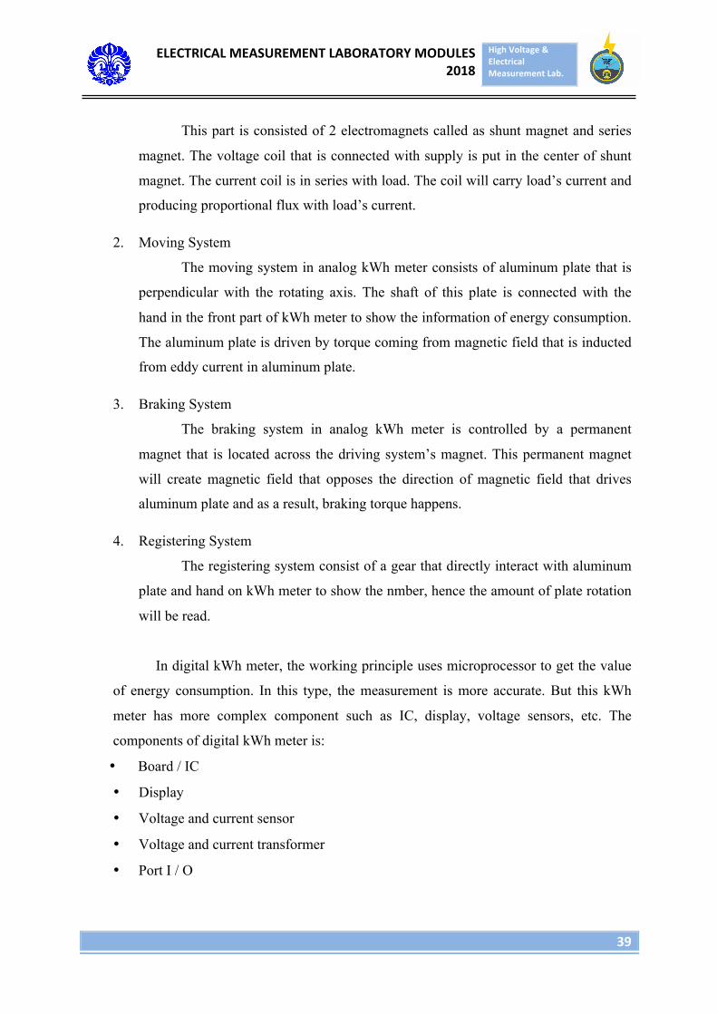
Here is the flowchart of process in digital kWh meter:
Figure 2. The flowchart of process in digital kWh meter
III. EXPERIMENT EQUIPMENT
1. Analog KWh meter
2. Cables
3. Digital wattmeter
4. Lamp Fitting
5. 10 100 W lamps
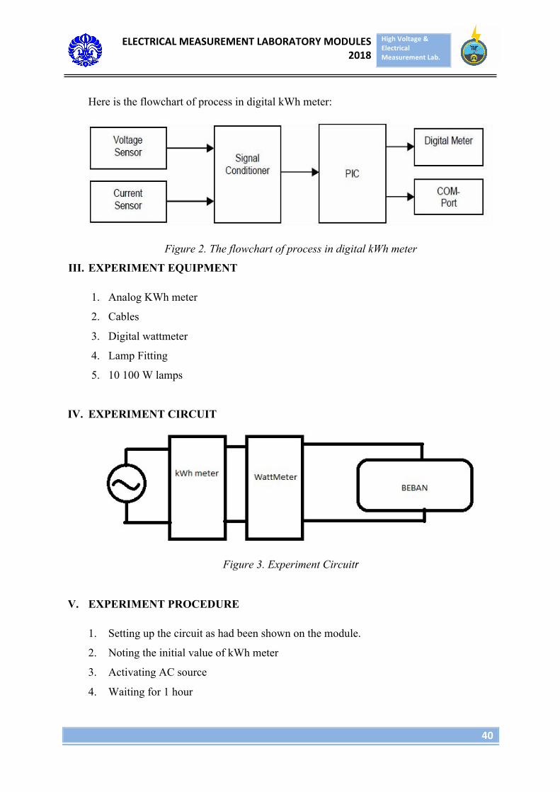
IV. EXPERIMENT CIRCUIT
Figure 3. Experiment Circuitr
V. EXPERIMENT PROCEDURE
1. Setting up the circuit as had been shown on the module.
2. Noting the initial value of kWh meter
3. Activating AC source
4. Waiting for 1 hour
ELECTRICALMEASUREMENTLABORATORYMODULES2018
HighVoltage&ElectricalMeasurementLab.
41
5. Noting the result of kWh meter’s measurement
6. Comparing data from kWh meter, length of experiment, load power and the reading
of wattmeter.
ELECTRICALMEASUREMENTLABORATORYMODULES2018
HighVoltage&ElectricalMeasurementLab.
42
MODULE 8
POST TEST
Post test is a final test on all the materials during the Electrical Measurement
laboratory activity. All students taking this course must take the post test and it will be
included in the final scoring. The time and the place of post test will be informed later on.