Embed Size (px)
Citation preview
1
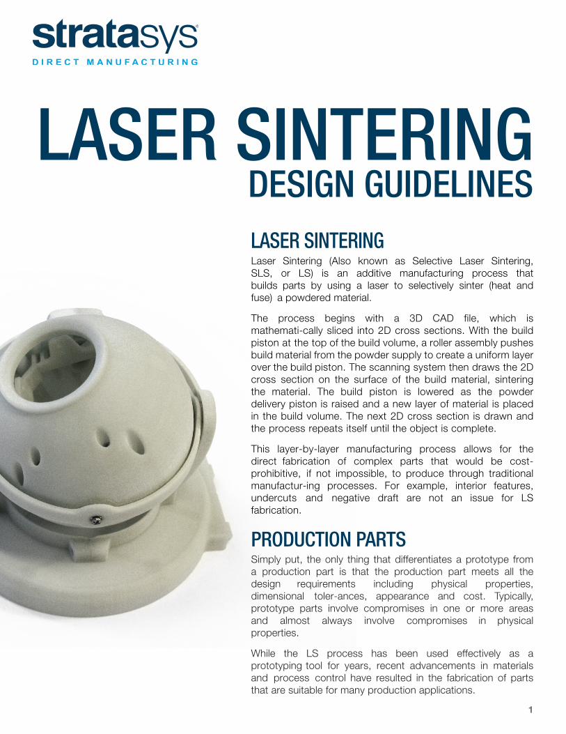
LASER SINTERING DESIGN GUIDELINESLASER SINTERING Laser Sintering (Also known as Selective Laser Sintering, SLS, or LS) is an additive manufacturing process that builds parts by using a laser to selectively sinter (heat and fuse) a powdered material.
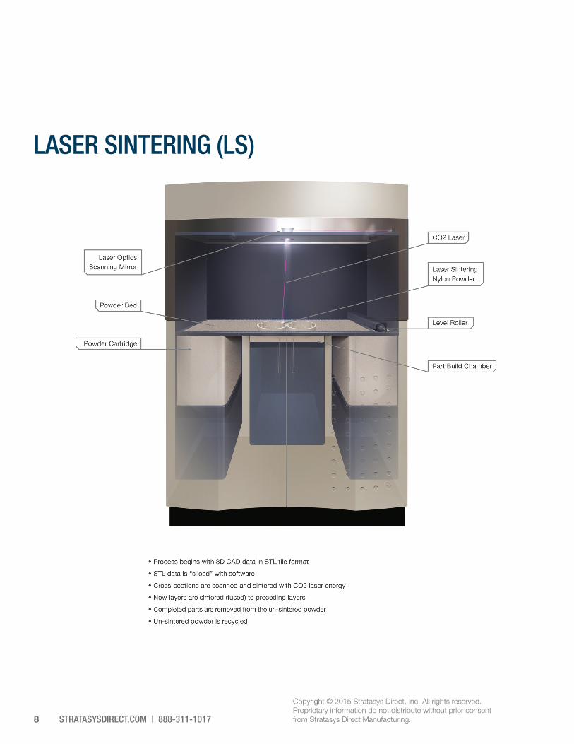
The process begins with a 3D CAD file, which is mathemati-cally sliced into 2D cross sections. With the build piston at the top of the build volume, a roller assembly pushes build material from the powder supply to create a uniform layer over the build piston. The scanning system then draws the 2D cross section on the surface of the build material, sintering the material. The build piston is lowered as the powder delivery piston is raised and a new layer of material is placed in the build volume. The next 2D cross section is drawn and the process repeats itself until the object is complete.
This layer-by-layer manufacturing process allows for the direct fabrication of complex parts that would be cost-prohibitive, if not impossible, to produce through traditional manufactur-ing processes. For example, interior features, undercuts and negative draft are not an issue for LS fabrication.
PRODUCTION PARTSSimply put, the only thing that differentiates a prototype from a production part is that the production part meets all the design requirements including physical properties, dimensional toler-ances, appearance and cost. Typically, prototype parts involve compromises in one or more areas and almost always involve compromises in physical properties.
While the LS process has been used effectively as a prototyping tool for years, recent advancements in materials and process control have resulted in the fabrication of parts that are suitable for many production applications.
2
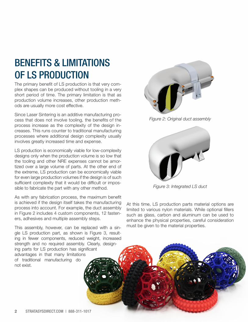
Figure 3: Integrated LS duct
At this time, LS production parts material options are limited to various nylon materials. While optional fillers such as glass, carbon and aluminum can be used to enhance the physical properties, careful consideration must be given to the material properties.
Figure 2: Original duct assembly
BENEFITS & LIMITATIONS OF LS PRODUCTIONThe primary benefit of LS production is that very com-plex shapes can be produced without tooling in a very short period of time. The primary limitation is that as production volume increases, other production meth-ods are usually more cost effective.
Since Laser Sintering is an additive manufacturing pro-cess that does not involve tooling, the benefits of the process increase as the complexity of the design in-creases. This runs counter to traditional manufacturing processes where additional design complexity usually involves greatly increased time and expense.
LS production is economically viable for low-complexity designs only when the production volume is so low that the tooling and other NRE expenses cannot be amor-tized over a large volume of parts. At the other end of the extreme, LS production can be economically viable for even large production volumes if the design is of such sufficient complexity that it would be difficult or impos-sible to fabricate the part with any other method.
As with any fabrication process, the maximum benefit is achieved if the design itself takes the manufacturing process into account. For example, the duct assembly in Figure 2 includes 4 custom components, 12 fasten-ers, adhesives and multiple assembly steps.
This assembly, however, can be replaced with a sin-gle LS production part, as shown is Figure 3, result-ing in fewer components, reduced weight, increased strength and no required assembly. Clearly, design-ing parts for LS production has significant advantages in that many limitations of traditional manufacturing do not exist.
STRATASYSDIRECT.COM | 888-311-1017
3
LS PRODUCTION DESIGN CONSIDERATIONSThis document does not attempt to address all the pos-sible issues involved in designing mechanical compo-nents, but it will address the primary differences between designing parts for injection molding and LS production.
As with any manufacturing process, a number of issues can impact the performance of a particular design. One of the key advantages of LS production is that the LS prototypes can be used to quickly and easily verify the design. As with parts designed for other manufactur-ing processes, parts designed for LS production benefit from prototyping early and often.
In many ways, designing parts for LS production is very similar to designing parts for injection molding, with a few key differences:
• Undercuts, negative draft and interior features arenot a problem for LS parts.
• LS parts should have a minimum wall thickness of0.040 inches (1.0 mm).
• Holes in large blocks of material will be smallerthan specified due to “hoop” shrink. Keeping wallthickness at 0.120 inches (3.0 mm) or less willminimize this effect.
• The LS process adds a natural 0.015 inch (0.4mm) radius, so it’s not necessary to add a breakedge radius, unless additional stress relief is re-quired. If a radius of less than 0.015 inch (0.4 mm)is specified, the natural 0.015 inch (0.4 mm) ra-dius will be constructed.
• The LS process is capable of constructing 90°interior corners. It is recommended that a 0.015inch (0.4 mm) radius fillet be designed on all inte-rior corners for stress relief.
MATERIAL CONSIDERATIONSLS production materials are typically based on nylon powder, with optional fillers such as glass, carbon or aluminum. Sintered nylon differs from injection-molded nylon in a number of key areas, such as elongation at break. While typical injection-molded nylon may have an elongation at break of over 100%, LS materials range from 2-28%.
Stratasys Direct Manufacturing provides a wide variety of LS materials suitable for LS production applications. Detailed material specifications are available from www. stratasysdirect.com. The general information provided below is helpful in understanding some of the material issues associated with designing LS production parts.
PHYSICAL PROPERTIESStratasys Direct Manufacturing offers a range of LS materials to address a variety of production applications. Stratasys Direct Manufacturing’s NyTek™ 1100 is a high-elongation polyamide-based material specifically formulated for end use production. Glass, carbon and aluminum filled materials are also available.
COLORSLS materials are available in white, gray and black, although not all materials are available in each color. Basic coloring for LS is also available with Stratasys Direct Manufacturing’s proprietary ColorTek process. Colors available with this process are red, orange, yellow, green, blue and black.
NEED HELP SELECTING THE BEST TECHNOLOGY AND MATERIAL FOR YOUR PROJECT? CONTACT STRATASYS DIRECT MANUFACTURING’S KNOWLEDGEABLE PROJECT ENGINEERS FOR GUIDANCE AT 888-311-1017.
STRATASYSDIRECT.COM | 888-311-10174
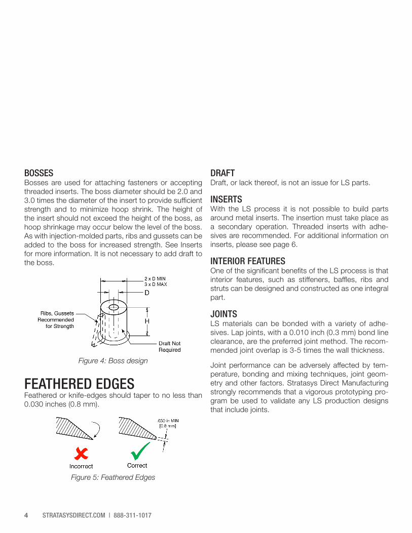
BOSSESBosses are used for attaching fasteners or accepting threaded inserts. The boss diameter should be 2.0 and 3.0 times the diameter of the insert to provide sufficient strength and to minimize hoop shrink. The height of the insert should not exceed the height of the boss, as hoop shrinkage may occur below the level of the boss. As with injection-molded parts, ribs and gussets can be added to the boss for increased strength. See Inserts for more information. It is not necessary to add draft to the boss.
FEATHERED EDGESFeathered or knife-edges should taper to no less than 0.030 inches (0.8 mm).
DRAFTDraft, or lack thereof, is not an issue for LS parts.
INSERTSWith the LS process it is not possible to build parts around metal inserts. The insertion must take place as a secondary operation. Threaded inserts with adhe-sives are recommended. For additional information on inserts, please see page 6.
INTERIOR FEATURESOne of the significant benefits of the LS process is that interior features, such as stiffeners, baffles, ribs and struts can be designed and constructed as one integral part.
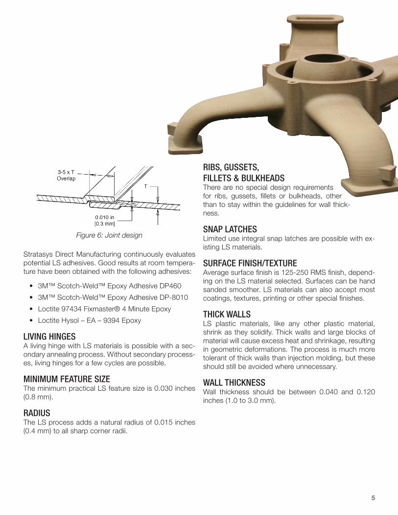
JOINTSLS materials can be bonded with a variety of adhe-sives. Lap joints, with a 0.010 inch (0.3 mm) bond line clearance, are the preferred joint method. The recom-mended joint overlap is 3-5 times the wall thickness.
Joint performance can be adversely affected by tem-perature, bonding and mixing techniques, joint geom-etry and other factors. Stratasys Direct Manufacturing strongly recommends that a vigorous prototyping pro-gram be used to validate any LS production designs that include joints.
Figure 4: Boss design
Figure 5: Feathered Edges
5
Figure 6: Joint design
Stratasys Direct Manufacturing continuously evaluates potential LS adhesives. Good results at room tempera-ture have been obtained with the following adhesives:
• 3M™ Scotch-Weld™ Epoxy Adhesive DP460
• 3M™ Scotch-Weld™ Epoxy Adhesive DP-8010
• Loctite 97434 Fixmaster® 4 Minute Epoxy
• Loctite Hysol – EA – 9394 Epoxy
LIVING HINGESA living hinge with LS materials is possible with a sec-ondary annealing process. Without secondary process-es, living hinges for a few cycles are possible.
MINIMUM FEATURE SIZEThe minimum practical LS feature size is 0.030 inches (0.8 mm).
RADIUSThe LS process adds a natural radius of 0.015 inches (0.4 mm) to all sharp corner radii.
RIBS, GUSSETS, FILLETS & BULKHEADSThere are no special design requirements for ribs, gussets, fillets or bulkheads, other than to stay within the guidelines for wall thick-ness.
SNAP LATCHESLimited use integral snap latches are possible with ex-isting LS materials.
SURFACE FINISH/TEXTUREAverage surface finish is 125-250 RMS finish, depend-ing on the LS material selected. Surfaces can be hand sanded smoother. LS materials can also accept most coatings, textures, printing or other special finishes.
THICK WALLSLS plastic materials, like any other plastic material, shrink as they solidify. Thick walls and large blocks of material will cause excess heat and shrinkage, resulting in geometric deformations. The process is much more tolerant of thick walls than injection molding, but these should still be avoided where unnecessary.
WALL THICKNESSWall thickness should be between 0.040 and 0.120 inches (1.0 to 3.0 mm).
STRATASYSDIRECT.COM | 888-311-10176
DIMENSIONAL ACCURACYTypical tolerances are ± .015 inches (0.4 mm) or ± .003 inch/inch (0.1 mm/mm), whichever is greater. Tighter tol-erances may be offered on a case-by-case basis.
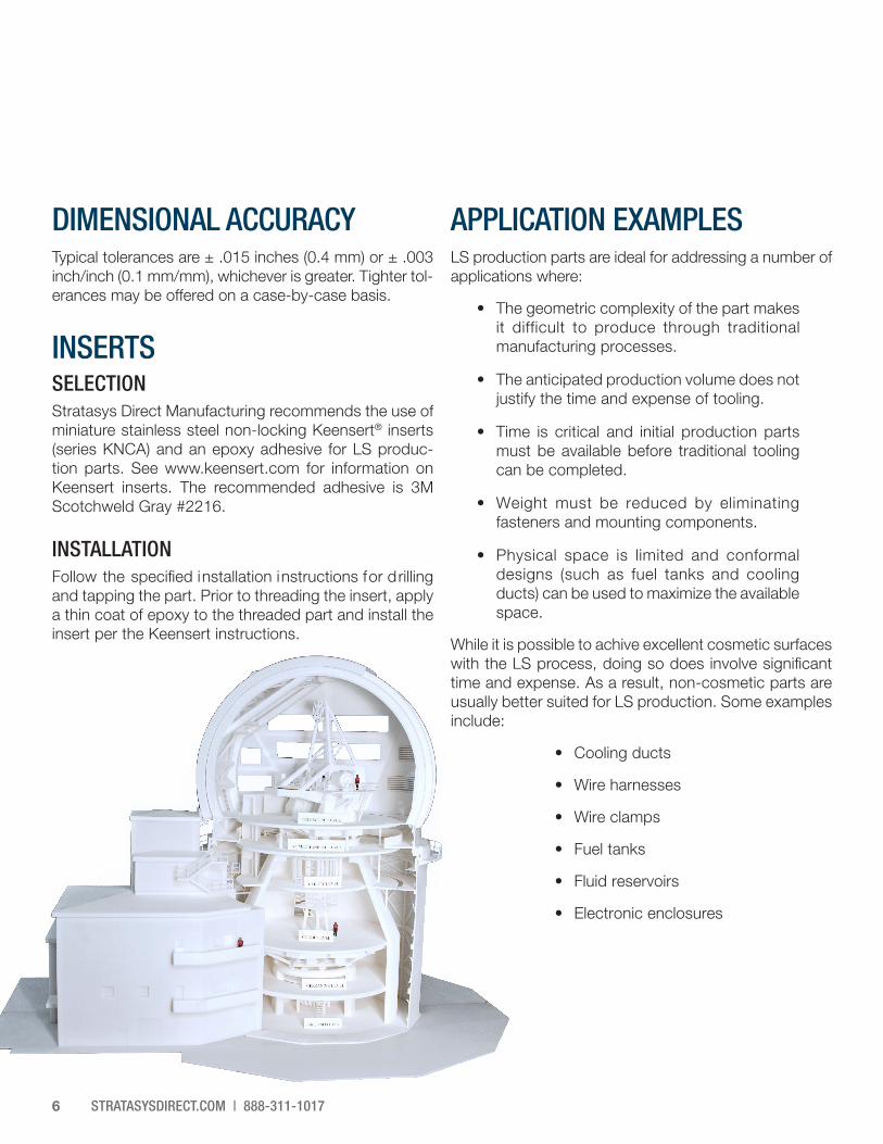
INSERTSSELECTIONStratasys Direct Manufacturing recommends the use of miniature stainless steel non-locking Keensert® inserts (series KNCA) and an epoxy adhesive for LS produc-tion parts. See www.keensert.com for information on Keensert inserts. The recommended adhesive is 3M Scotchweld Gray #2216.
INSTALLATIONFollow the specified installation instructions for drilling and tapping the part. Prior to threading the insert, apply a thin coat of epoxy to the threaded part and install the insert per the Keensert instructions.
APPLICATION EXAMPLESLS production parts are ideal for addressing a number of applications where:
• The geometric complexity of the part makesit difficult to produce through traditionalmanufacturing processes.
• The anticipated production volume does notjustify the time and expense of tooling.
• Time is critical and initial production partsmust be available before traditional toolingcan be completed.
• Weight must be reduced by eliminatingfasteners and mounting components.
• Physical space is limited and conformaldesigns (such as fuel tanks and coolingducts) can be used to maximize the availablespace.
While it is possible to achive excellent cosmetic surfaces with the LS process, doing so does involve significant time and expense. As a result, non-cosmetic parts are usually better suited for LS production. Some examples include:
• Cooling ducts
• Wire harnesses
• Wire clamps
• Fuel tanks
• Fluid reservoirs
• Electronic enclosures
7
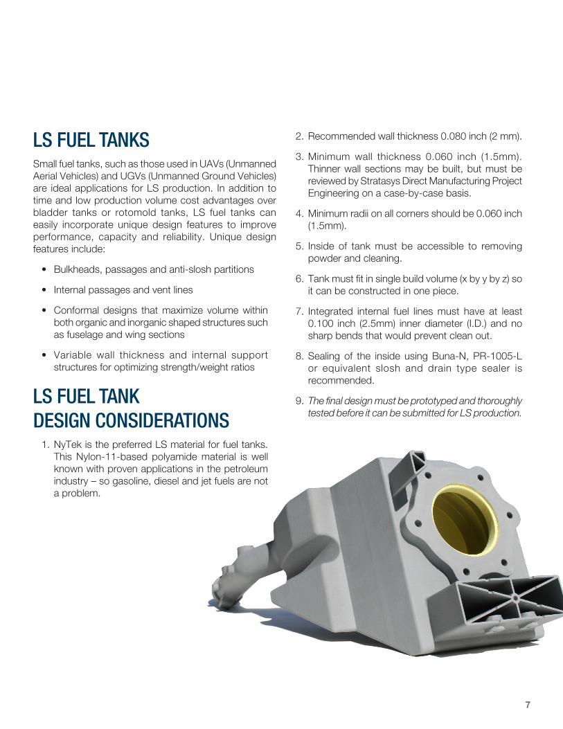
LS FUEL TANKSSmall fuel tanks, such as those used in UAVs (Unmanned Aerial Vehicles) and UGVs (Unmanned Ground Vehicles) are ideal applications for LS production. In addition to time and low production volume cost advantages over bladder tanks or rotomold tanks, LS fuel tanks can easily incorporate unique design features to improve performance, capacity and reliability. Unique design features include:
• Bulkheads, passages and anti-slosh partitions
• Internal passages and vent lines
• Conformal designs that maximize volume withinboth organic and inorganic shaped structures suchas fuselage and wing sections
• Variable wall thickness and internal supportstructures for optimizing strength/weight ratios
LS FUEL TANK DESIGN CONSIDERATIONS
1. NyTek is the preferred LS material for fuel tanks.This Nylon-11-based polyamide material is wellknown with proven applications in the petroleumindustry – so gasoline, diesel and jet fuels are nota problem.
2. Recommended wall thickness 0.080 inch (2 mm).
3. Minimum wall thickness 0.060 inch (1.5mm).Thinner wall sections may be built, but must bereviewed by Stratasys Direct Manufacturing ProjectEngineering on a case-by-case basis.
4. Minimum radii on all corners should be 0.060 inch(1.5mm).
5. Inside of tank must be accessible to removingpowder and cleaning.
6. Tank must fit in single build volume (x by y by z) soit can be constructed in one piece.
7. Integrated internal fuel lines must have at least0.100 inch (2.5mm) inner diameter (I.D.) and nosharp bends that would prevent clean out.
8. Sealing of the inside using Buna-N, PR-1005-Lor equivalent slosh and drain type sealer isrecommended.
9. The final design must be prototyped and thoroughlytested before it can be submitted for LS production.
STRATASYSDIRECT.COM | 888-311-10178
LASER SINTERING (LS)
Copyright © 2015 Stratasys Direct, Inc. All rights reserved. Proprietary information do not distribute without prior consent from Stratasys Direct Manufacturing.