Embed Size (px)
Citation preview

����������
mxchipWNetTM-DTUAdvanced settings
13�1�10����
MXCHIP All rights reserved

����������
Agenda
• UART data’s integrity
• UART frame control
• Power save management
• TCP maintenance settings
• Multiple AP roaming and dual mode
• Firmware update mode, MFG mode
13�1�10����
MXCHIP All rights reserved

����������
mxchipWNetTM-DTUUART data’s integrity
13�1�10����
MXCHIP All rights reserved
����������
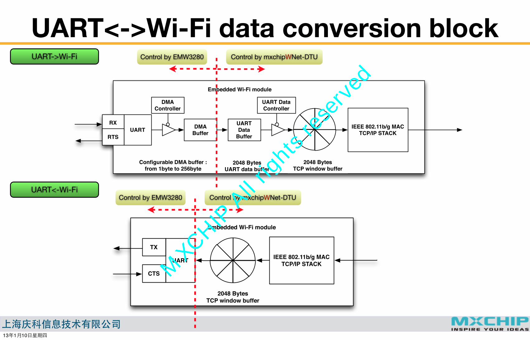
UART<->Wi-Fi data conversion block
Embedded Wi-Fi module
IEEE 802.11b/g MACTCP/IP STACK
2048 BytesTCP window buffer
DMA Buffer
DMA Controller
UART
Configurable DMA buffer : from 1byte to 256byte
RX
RTS
UART Data
Buffer
UART Data Controller
2048 BytesUART data buffer
UART->Wi-Fi
Embedded Wi-Fi module
IEEE 802.11b/g MACTCP/IP STACK
2048 BytesTCP window buffer
UART
TX
CTS
UART<-Wi-Fi
Control by EMW3280 Control by mxchipWNet-DTU
Control by EMW3280 Control by mxchipWNet-DTU
13�1�10����
MXCHIP All rights reserved
����������
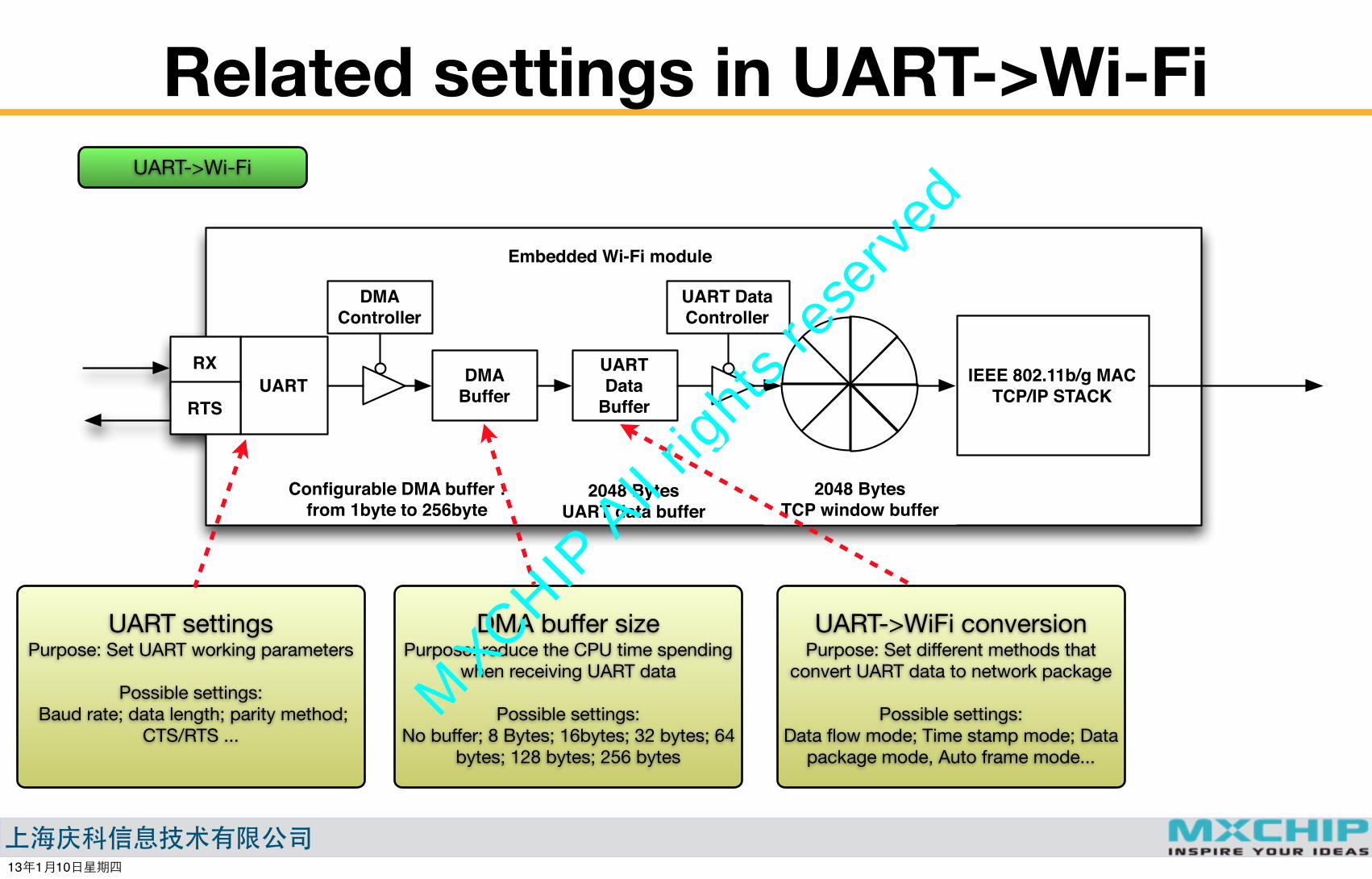
Related settings in UART->Wi-Fi
Embedded Wi-Fi module
IEEE 802.11b/g MACTCP/IP STACK
2048 BytesTCP window buffer
DMA Buffer
DMA Controller
UART
Configurable DMA buffer : from 1byte to 256byte
RX
RTS
UART Data
Buffer
UART Data Controller
2048 BytesUART data buffer
UART->Wi-Fi
DMA buffer sizePurpose: reduce the CPU time spending
when receiving UART data
Possible settings:No buffer; 8 Bytes; 16bytes; 32 bytes; 64
bytes; 128 bytes; 256 bytes
UART settingsPurpose: Set UART working parameters
Possible settings: Baud rate; data length; parity method;
CTS/RTS ...
UART->WiFi conversionPurpose: Set different methods that
convert UART data to network package
Possible settings:Data flow mode; Time stamp mode; Data
package mode, Auto frame mode...
13�1�10����
MXCHIP All rights reserved

����������
UART data lost case in UART->Wi-FiUART->Wi-Fi
Embedded Wi-Fi module
IEEE 802.11b/g MACTCP/IP STACK
2048 BytesTCP window buffer
DMA Buffer
DMA Controller
UART
Configurable DMA buffer : from 1byte to 256byte
RX
RTS
UART Data
Buffer
UART Data Controller
2048 BytesUART data buffer
Wi-Fi data transmission is blocked.
5kbytes/s: 800ms10kbytes/s: 400ms50kbytes/s: 80ms
100kbytes/s: 40ms
No more space for additional UART data.
Host is still sending UART data.
Data delay or block is very common due to wireless or heavy
traffic on network .
13�1�10����
MXCHIP All rights reserved

����������
UART data integrity, Method 1 Add an ACK mechanism over communication protocol
Wi-Fi moduleUART Device Remote device
Send UART data (s=n)
Send Wi-Fi data (s=n)
Send ACK package (s=n)
Send ACK package over UART (s=n)
Send UART data (s=n+1)
Send ACK package over UART (s=n+1)
Send Wi-Fi data (s=n+1)
Send ACK package (s=n+1)
No more UART data should be sent to Wi-Fi module if the previous ACK package is not
received.
Wait the ACK package before send the next data
13�1�10����
MXCHIP All rights reserved
����������
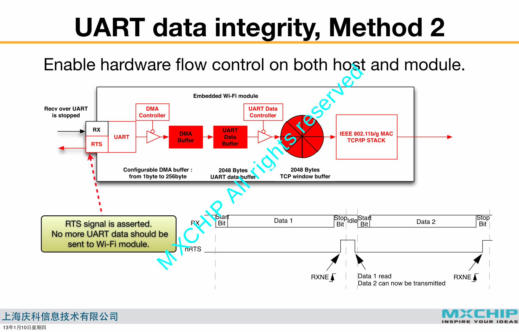
UART data integrity, Method 2 Enable hardware flow control on both host and module.
Embedded Wi-Fi module
IEEE 802.11b/g MACTCP/IP STACK
2048 BytesTCP window buffer
DMA Buffer
DMA Controller
UART
Configurable DMA buffer : from 1byte to 256byte
RX
RTS
UART Data
Buffer
UART Data Controller
2048 BytesUART data buffer
Recv over UART is stopped
RTS signal is asserted. No more UART data should be
sent to Wi-Fi module.
Universal synchronous asynchronous receiver transmitter (USART) RM0008
764/1072 Doc ID 13902 Rev 11
RTS flow control
If the RTS flow control is enabled (RTSE=1), then nRTS is asserted (tied low) as long as the USART receiver is ready to receive new data. When the receive register is full, nRTS is deasserted, indicating that the transmission is expected to stop at the end of the current frame. Figure 299 shows an example of communication with RTS flow control enabled.
Figure 299. RTS flow control
CTS flow control
If the CTS flow control is enabled (CTSE=1), then the transmitter checks the nCTS input before transmitting the next frame. If nCTS is asserted (tied low), then the next data is transmitted (assuming that a data is to be transmitted, in other words, if TXE=0), else the transmission does not occur. When nCTS is deasserted during a transmission, the current transmission is completed before the transmitter stops.
When CTSE=1, the CTSIF status bit is automatically set by hardware as soon as the nCTS input toggles. It indicates when the receiver becomes ready or not ready for communication. An interrupt is generated if the CTSIE bit in the USART_CR3 register is set. The figure below shows an example of communication with CTS flow control enabled.
Figure 300. CTS flow control
StartBit
StopBitData 1 IdleStart
BitStopBitData 2RX
nRTS
RXNE Data 1 read RXNE Data 2 can now be transmitted
StartBit
StopBitData 2 Idle Start
Bit Data 3TX
nCTS
CTS
Transmission of Data 3
Data 1 StopBit
is delayed until nCTS = 0
CTS
Data 2 Data 3empty empty
Transmit data register
TDR
Writing data 3 in TDR
13�1�10����
MXCHIP All rights reserved
����������
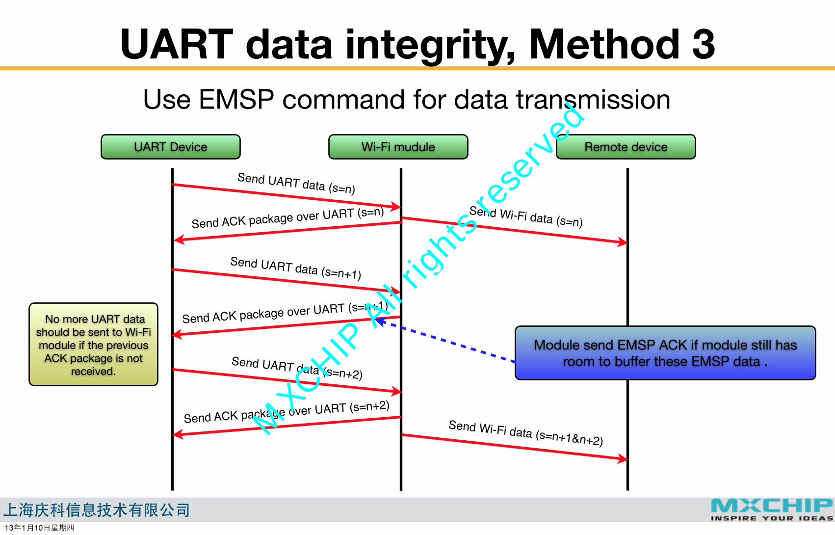
UART data integrity, Method 3 Use EMSP command for data transmission
Wi-Fi muduleUART Device Remote device
Send UART data (s=n)Send Wi-Fi data (s=n)Send ACK package over UART (s=n)
Send UART data (s=n+1)
Send ACK package over UART (s=n+1)
Send Wi-Fi data (s=n+1&n+2)
No more UART data should be sent to Wi-Fi module if the previous ACK package is not
received.Send UART data (s=n+2)
Send ACK package over UART (s=n+2)
Module send EMSP ACK if module still has room to buffer these EMSP data .
13�1�10����
MXCHIP All rights reserved

����������
Comparison
Method 1 Method 2 Method 3
Additional hardware connection
Transfer speed
UART data package format
Configuration
No Yes No
Low Fast Middle, but much faster than method 1
User define User define EMSP command
DTU mode (status = 1) CTS/RTS == Enable
DTU mode (status = 1) CTS/RTS == EnableDMA buffer size > 16
EMSP mode (status = 0)
13�1�10����
MXCHIP All rights reserved

����������
mxchipWNetTM-DTUUART frame control
13�1�10����
MXCHIP All rights reserved

����������
UART frame control: Data flow mode• Data frame is used to fetch the target data from data flow
• Wi-Fi network has standard data package definition: TCP, UDP, HTML, etc...
• UART data formats are all user defined
Treat UART data as data flow: DATA mode = Data Flow Mode, UART DMA Size=0, TCP data frame:
UART Data frames
Treat UART data as data flow: DATA mode = Data Flow Mode, UART DMA Size=8, TCP data frame
UART frame
TCP frame
Recv n bytes at one time, rebuild the UART data frame in receiver’s UART buffer.
Recv n package bytes at one time, rebuild the UART data frame in receiver’s data buffer.
13�1�10����
MXCHIP All rights reserved

����������
Time stamp mode• Data flow mode
• If UART data buffer has data ,try to send them as soon as possible.
• Advantage: UART data is sent to Wi-Fi very fast.
• Disadvantage: TCP data is fragmental, each TCP package has little useful UART data, and import too much TCP framework data (TCP head and TCP tail) .
• Time stamp mode
• If UART data buffer has data, wait a pre-configured time or buffer is full, then send them.
• Advantage: The quality of TCP package is reduced, Network performance is better.
• Disadvantage: Data has a delay if UART data length is short
Pre-configured time delay
13�1�10����
MXCHIP All rights reserved

����������
Package mode and Auto frame mode• Put one UART package in one network package would simplify the
package recognition on the remote network device.
UART Data frames
Detect UART data’s package: DATA mode = package mode or auto frame mode
Time interval between two package > 50ms,in auto frame mode
13�1�10����
MXCHIP All rights reserved

����������
Package mode formatPackage mode 1
Package mode 2
0x7E Length(n+1) Data1 Data2 Data3 Data4 ............ Data
n-1Data
n 0xCE
0x7E Length,2bytes : (n+1) Data1 Data2 Data3 Data4 ............ Data
n-1Data
n 0xCE
0x7E Length(n+1) Data1 Data2 Data3 Data4 ............ Data
n-1Data
n 0xCETCP/UDP head TCP/UDP tail
Data1 Data2 Data3 Data4 ............ Datan-1
DatanTCP/UDP head TCP/UDP tail
13�1�10����
MXCHIP All rights reserved

����������
IO1: Frame control mode
UART Data frames
Detect UART data’s package: DATA mode = Dara Flow mode, IO1 = Frame control mode
IO1
13�1�10����
MXCHIP All rights reserved
����������
mxchipWNetTM-DTULow Power Modes
13�1�10����
MXCHIP All rights reserved
����������
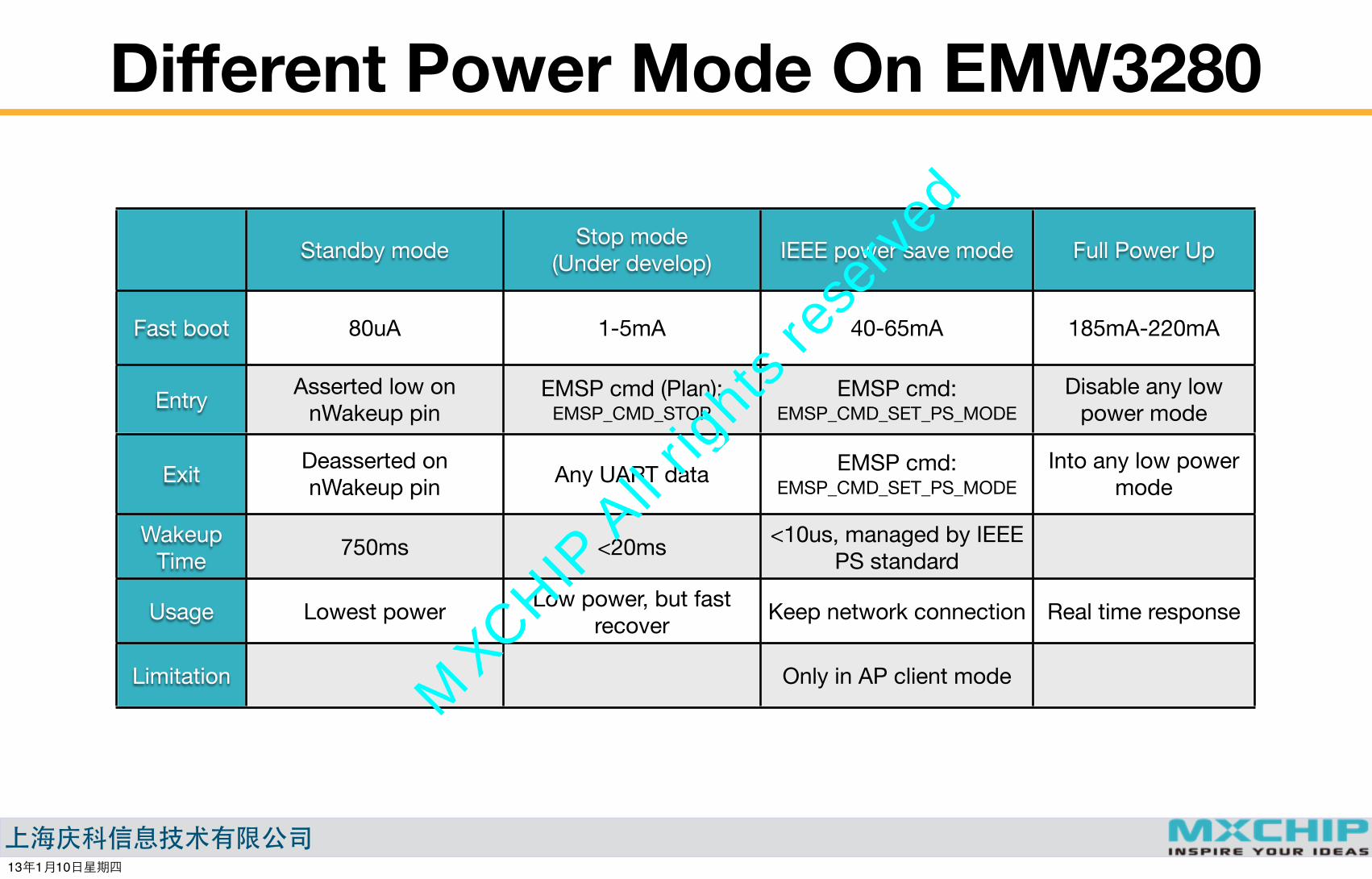
Different Power Mode On EMW3280
Standby mode Stop mode(Under develop) IEEE power save mode Full Power Up
Fast boot
Entry
Exit
Wakeup Time
Usage
Limitation
80uA 1-5mA 40-65mA 185mA-220mA
Asserted low on nWakeup pin
EMSP cmd (Plan):EMSP_CMD_STOP
EMSP cmd:EMSP_CMD_SET_PS_MODE
Disable any low power mode
Deasserted on nWakeup pin Any UART data EMSP cmd:
EMSP_CMD_SET_PS_MODEInto any low power
mode
750ms <20ms <10us, managed by IEEE PS standard
Lowest power Low power, but fast recover Keep network connection Real time response
Only in AP client mode
13�1�10����
MXCHIP All rights reserved

����������
IEEE PS mode: Principle
P o w e r s a v i n g b a s i c s
To assist stations with power saving, Access Points (APs) are designed to buffer frames for a station when that station is in power save mode and to transmit them later to the station when the AP knows the station will listen. When a station is in power save mode, it turns off its transmitter and receiver to preserve energy. It takes less power for a station to turn its receiver on to listen to frames than to turn it its transmitter on to transmit frames.
T a r g e t B e a c o n T r a n s m i s s i o n T i m e T i m e ( T B T T ) a n d b e a c o n i n t e r v a l
T h e T I M i n f o r m a t i o n e l e m e n t
D e l i v e r y T r a f f i c I n d i c a t i o n M a p ( D T I M ) , D T I M p e r i o d ( D T I M = 1 b e a c o n i n t e r v a l i n c u r r e n t c a s e )
13�1�10����
MXCHIP All rights reserved
����������
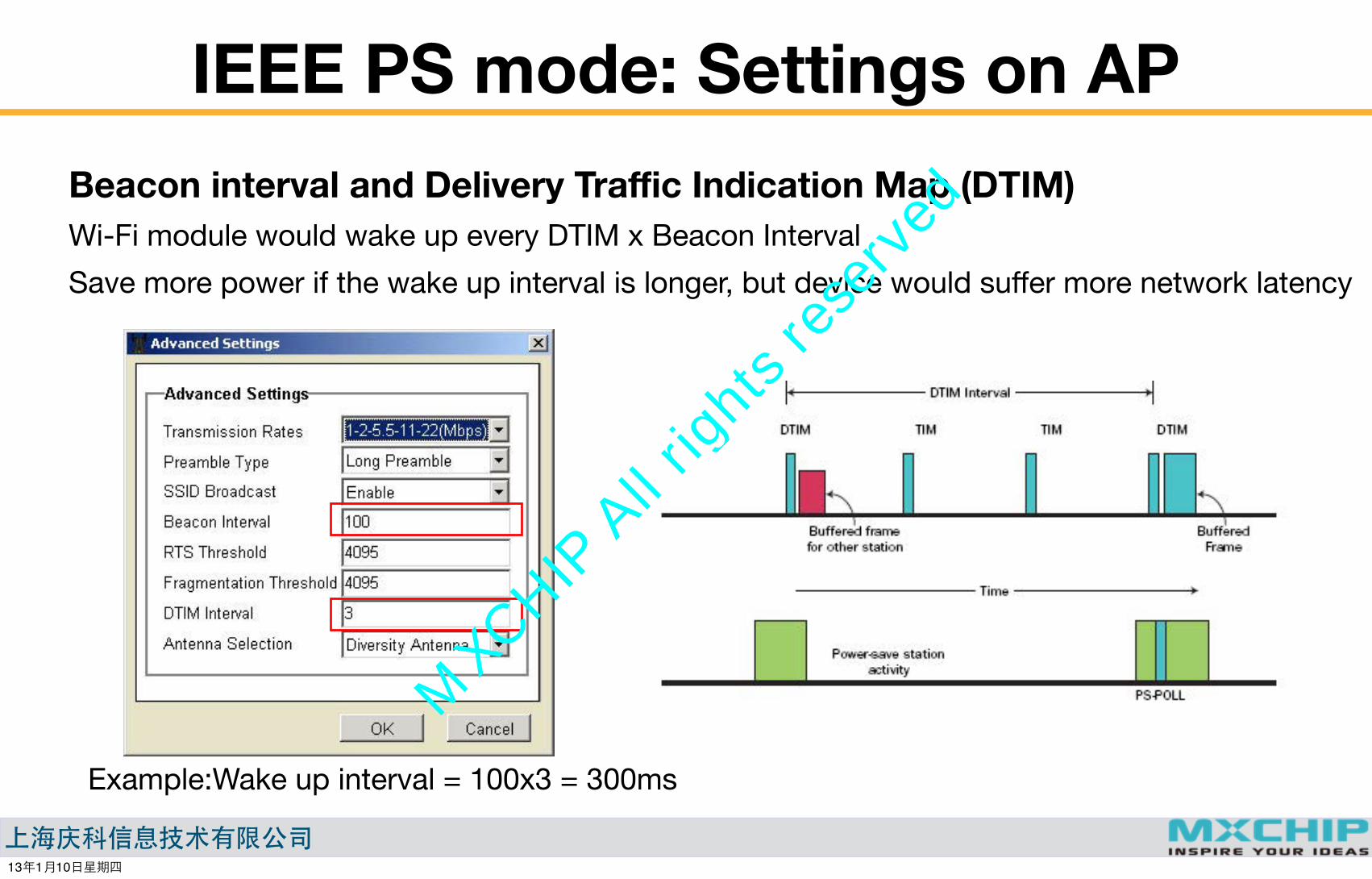
IEEE PS mode: Settings on APBeacon interval and Delivery Traffic Indication Map (DTIM)Wi-Fi module would wake up every DTIM x Beacon IntervalSave more power if the wake up interval is longer, but device would suffer more network latency
Example:Wake up interval = 100x3 = 300ms
13�1�10����
MXCHIP All rights reserved
����������
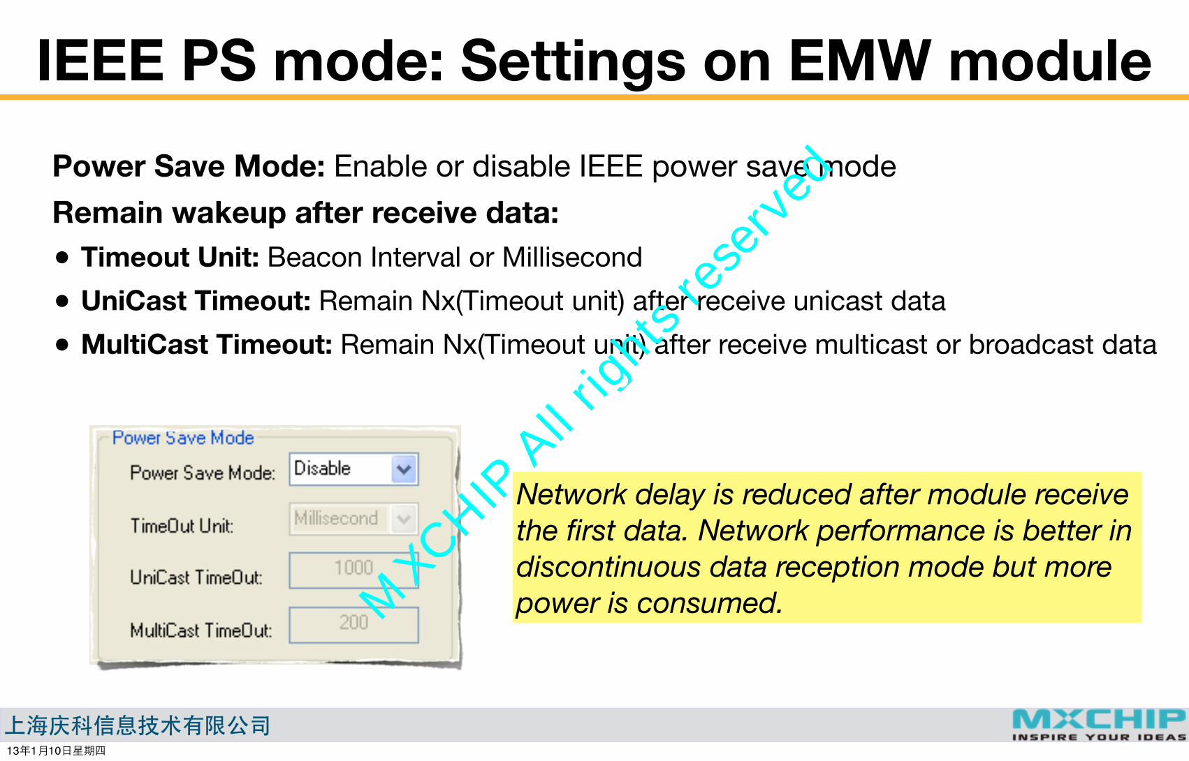
IEEE PS mode: Settings on EMW modulePower Save Mode: Enable or disable IEEE power save mode Remain wakeup after receive data:• Timeout Unit: Beacon Interval or Millisecond
• UniCast Timeout: Remain Nx(Timeout unit) after receive unicast data
• MultiCast Timeout: Remain Nx(Timeout unit) after receive multicast or broadcast data
Network delay is reduced after module receive the first data. Network performance is better in discontinuous data reception mode but more power is consumed.
13�1�10����
MXCHIP All rights reserved
����������
mxchipWNetTM-DTUManage TCP Connections
13�1�10����
MXCHIP All rights reserved
����������
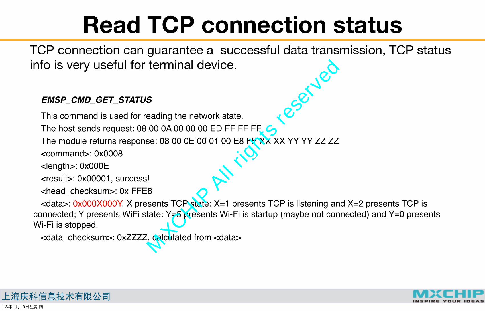
Read TCP connection statusTCP connection can guarantee a successful data transmission, TCP status info is very useful for terminal device.
EMSP_CMD_GET_STATUS
This command is used for reading the network state.The host sends request: 08 00 0A 00 00 00 ED FF FF FFThe module returns response: 08 00 0E 00 01 00 E8 FF XX XX YY YY ZZ ZZ<command>: 0x0008<length>: 0x000E<result>: 0x00001, success!<head_checksum>: 0x FFE8<data>: 0x000X000Y. X presents TCP state: X=1 presents TCP is listening and X=2 presents TCP is
connected; Y presents WiFi state: Y=5 presents Wi-Fi is startup (maybe not connected) and Y=0 presents Wi-Fi is stopped.
<data_checksum>: 0xZZZZ, calculated from <data>
13�1�10����
MXCHIP All rights reserved
����������
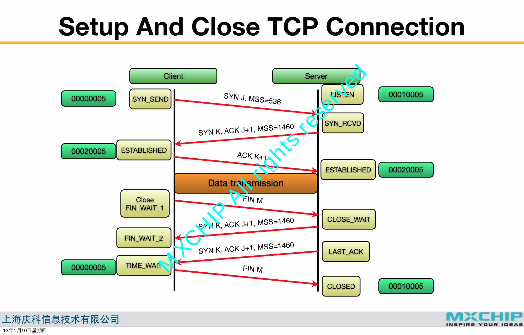
Setup And Close TCP ConnectionServerClient
SYN J, MSS=536
SYN K, ACK J+1, MSS=1460
FIN M
SYN_SEND
SYN_RCVD
ESTABLISHED ACK K+1ESTABLISHED
CloseFIN_WAIT_1
SYN K, ACK J+1, MSS=1460
SYN K, ACK J+1, MSS=1460
FIN M
FIN_WAIT_2
TIME_WAIT
CLOSE_WAIT
LAST_ACK
CLOSED
LISTEN00000005 00010005
00020005
00020005Data transmission
00000005
00010005
13�1�10����
MXCHIP All rights reserved

����������
TCP Connection Maintenance• Unexpected power down on TCP server/client
• Network disconnection
• Failed on network devices(Gateway, Router...)
• Uncompleted TCP close procedure...... TCP data transmission would be failed under above circumstances, so device should release any resource used by this TCP, mark it as closed and try to establish a new one.
Detection method:A Failed TCP data transmission(No ACK is received after data transmission): for fast detect while data is transmittingKeep-Alive message(A simulated data transmission): used while no data is transmitting on TCP conn.
13�1�10����
MXCHIP All rights reserved
����������
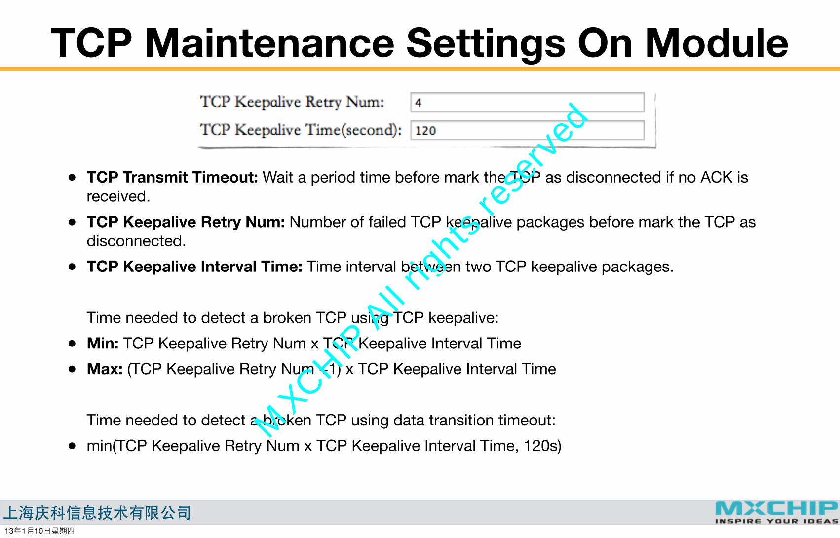
TCP Maintenance Settings On Module
• TCP Transmit Timeout: Wait a period time before mark the TCP as disconnected if no ACK is received.
• TCP Keepalive Retry Num: Number of failed TCP keepalive packages before mark the TCP as disconnected.
• TCP Keepalive Interval Time: Time interval between two TCP keepalive packages.
Time needed to detect a broken TCP using TCP keepalive:
• Min: TCP Keepalive Retry Num x TCP Keepalive Interval Time
• Max: (TCP Keepalive Retry Num +1) x TCP Keepalive Interval Time
Time needed to detect a broken TCP using data transition timeout:
• min(TCP Keepalive Retry Num x TCP Keepalive Interval Time, 120s)
13�1�10����
MXCHIP All rights reserved
����������
mxchipWNetTM-DTUOthers
13�1�10����
MXCHIP All rights reserved

����������
Multiple AP roaming
Use EMW Tool BoxUse EMW Tool Box
This function is only used in AP client mode and dual mode.Module try to connect another AP listed in Main AP and extra AP list after current connection is lost.
• Priory: Main AP>Extra AP 1>Extra AP 2>Extra AP 3>Extra AP 4
• If serval APs share the same SSID name and security settings, treat them as one.
13�1�10����
MXCHIP All rights reserved

����������
Dual ModeIn dual mode, module establish a soft AP while in AP client mode.Limitation•Soft AP conn. is only used for direct communicate with module, no router function provided
between soft AP and AP client (1).
•Communication between clients under soft AP is forbidden (2).
•Module’s IP address in Dual mode Soft AP is unchangeable : 11.11.11.1
•IEEE power save mode can not be used
Usage•Provide a always-on connection to config EMW module
•Provide a always-on connection for local remote controlAP client
Soft AP
XX
X
√√
(1)
(2)
13�1�10����
MXCHIP All rights reserved

����������
Firmware Update Mode
Firmware update over UART Refer AN0002 for details. Update from web page will be released in Dec. 2012
������
BOOT STATUS ������
0 0 MFG mode
0 1�Default� Firmware update mode
1�Default� 0 EMSP command mode
1�Default� 1�Default� DTU mode
1� �����
2������
3������������
Boot module to FW update mode UART para.: 115200/8/n/1, open update command interface with COM tools.
Input”1”, and send the bin file with Ymodem
13�1�10����
MXCHIP All rights reserved

����������
MFG mode
������
��!"���� ����
� �������
� �������
�������
��������� #
Boot module to FWG mode
Input test AP’s SSID to start test Extra test function on TCP/UDP data transmission
• Output firmware version
• Output module’s MAC address
• Search AP and display AP’s signal strength
• Connect a predefined AP
• DHCP test and ping AP
• Optional TCP/UDP test(define the remote device’s address before test)
13�1�10����
MXCHIP All rights reserved

����������
THE END
Make wireless connections Simple
Thank you!
13�1�10����
MXCHIP All rights reserved