Embed Size (px)
Citation preview
LCP Condylar Plate 4.5/5.0. Part of the LCP Periarticular Plating System.
Surgical Technique
This publication is not intended for distribution in the USA.
Instruments and implants approved by the AO Foundation.

LCP Condylar Plate 4.5/5.0 Surgical Technique DePuy Synthes 1
Table of Contents
Introduction
Surgical Technique
Product Information
MRI Information 28
Features and Benefits 2
AO Principles 4
Indications 6
7
Plates 21
Screws 22
Drill and Wire Guides 24
Sets 26
Image intensifier control
WarningThis description alone does not provide sufficient background for direct use of DePuy Synthes products. Instruction by a surgeon experienced in handling these products is highly recommended.
Processing, Reprocessing, Care and MaintenanceFor general guidelines, function control and dismantling of multi-part instruments, as well as processing guidelines for implants, please contact your local sales representative or refer to:http://emea.depuysynthes.com/hcp/reprocessing-care-maintenanceFor general information about reprocessing, care and maintenance of Synthes reusable devices, instrument trays and cases, as well as processing of Synthes non-sterile implants, please consult the Important Information leaflet (SE_023827) or refer to: http://emea.depuysynthes.com/hcp/reprocessing-care-maintenance
2 DePuy Synthes LCP Condylar Plate 4.5/5.0 Surgical Technique
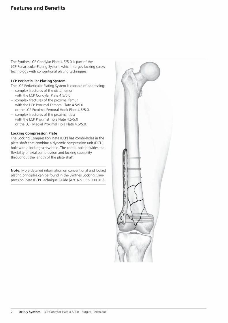
The Synthes LCP Condylar Plate 4.5/5.0 is part of the LCP Periarticular Plating System, which merges locking screw technology with conventional plating techniques.
LCP Periarticular Plating SystemThe LCP Periarticular Plating System is capable of addressing: – complex fractures of the distal femur
with the LCP Condylar Plate 4.5/5.0. – complex fractures of the proximal femur
with the LCP Proximal Femoral Plate 4.5/5.0 or the LCP Proximal Femoral Hook Plate 4.5/5.0.
– complex fractures of the proximal tibia with the LCP Proximal Tibia Plate 4.5/5.0 or the LCP Medial Proximal Tibia Plate 4.5/5.0.
Locking Compression PlateThe Locking Compression Plate (LCP) has combi-holes in the plate shaft that combine a dynamic compression unit (DCU) hole with a locking screw hole. The combi-hole provides the flexibility of axial compression and locking capability throughout the length of the plate shaft.
Note: More detailed information on conventional and locked plating principles can be found in the Synthes Locking Com-pression Plate (LCP) Technique Guide (Art. No. 036.000.019).
Features and Benefits
LCP Condylar Plate 4.5/5.0 Surgical Technique DePuy Synthes 3
LCP Condylar Plate SystemThe LCP Condylar Plate System has many similarities to tradi-tional plate fixation methods, with a few important improve-ments. The technical innovation of locking screws provides the ability to create a fixed-angle construct while using famil-iar AO plating techniques. Locking capability is important for a fixed-angle construct in osteopenic bone or multifrag-ment fractures where screw purchase is compromised. These screws do not rely on plate-to-bone compression to resist patient load, but function similarly to multiple, small angled blade plates.
– Locking screws engaged in the plate create a fixed-angle construct that improves fixation in osteopenic bone and multifragmentary fractures.
– Multiple screw fixation in the femoral condyles allows im-proved fixation of many distal fractures (including all C3 fractures).
– Low-profile, anatomically shaped plates designed for left or right femur.
– 316L stainless steel implants
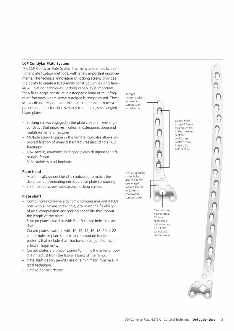
Plate head – Anatomically shaped head is contoured to match the
distal femur, eliminating intraoperative plate contouring. – Six threaded screw holes accept locking screws.
Plate shaft – Combi-holes combine a dynamic compression unit (DCU)
hole with a locking screw hole, providing the flexibility of axial compression and locking capability throughout the length of the plate.
– Straight plates available with 6 or 8 combi-holes in plate shaft.
– Curved plates available with 10, 12, 14, 16, 18, 20 or 22 combi-holes in plate shaft to accommodate fracture patterns that include shaft fractures in conjunction with articular fragments.
– Curved plates are precontoured to mimic the anterior bow (1.1 m radius) from the lateral aspect of the femur.
– Plate shaft design permits use of a minimally invasive sur-gical technique.
– Limited-contact design
Combi-holes accept 5.0 mm locking screws in the threaded section or 4.5 mm cortex screws in the DCU hole section.
Five surrounding screw holes accept 5.0 mm cannulated locking screws or 5.0 mm cannulated conical screws.
Accepts tension device to provide compression or distraction
Central screw hole accepts 7.3 mm cannulated locking screw or 7.3 mm cannulated conical screw.

4 DePuy Synthes LCP Condylar Plate 4.5/5.0 Surgical Technique
1 M.E. Müller, M. Allgöwer, R. Schneider, and H. Willenegger (1991). AO Manual of Internal Fixation, 3rd Edition. Berlin: Springer.
AO Principles
In 1958, the AO formulated four basic principles which have become the guidelines for internal fixation.1 Those principles as applied to the LCP Condylar Plate are:
Anatomic reductionFacilitates restoration of the articular surface using guide wires for reduction and insertion of cannulated screws. Precontoured plate assists reduction of metaphysis to dia-physis.
Stable fixationLocking screws create a fixed-angle construct, providing angular stability.
Preservation of blood supplyTapered end simplifies submuscular plate insertion, improving tissue viability. Limited-contact design reduces plate-to-bone contact and vascular trauma.

LCP Condylar Plate 4.5/5.0 Surgical Technique DePuy Synthes 5
Prevention of varus collapse by fixed-angle construct facilitates early callus formation.
Early mobilizationPlate features combined with AO technique create an environment for bone healing, expediting a return to optimal function.
6 DePuy Synthes LCP Condylar Plate 4.5/5.0 Surgical Technique
Indications
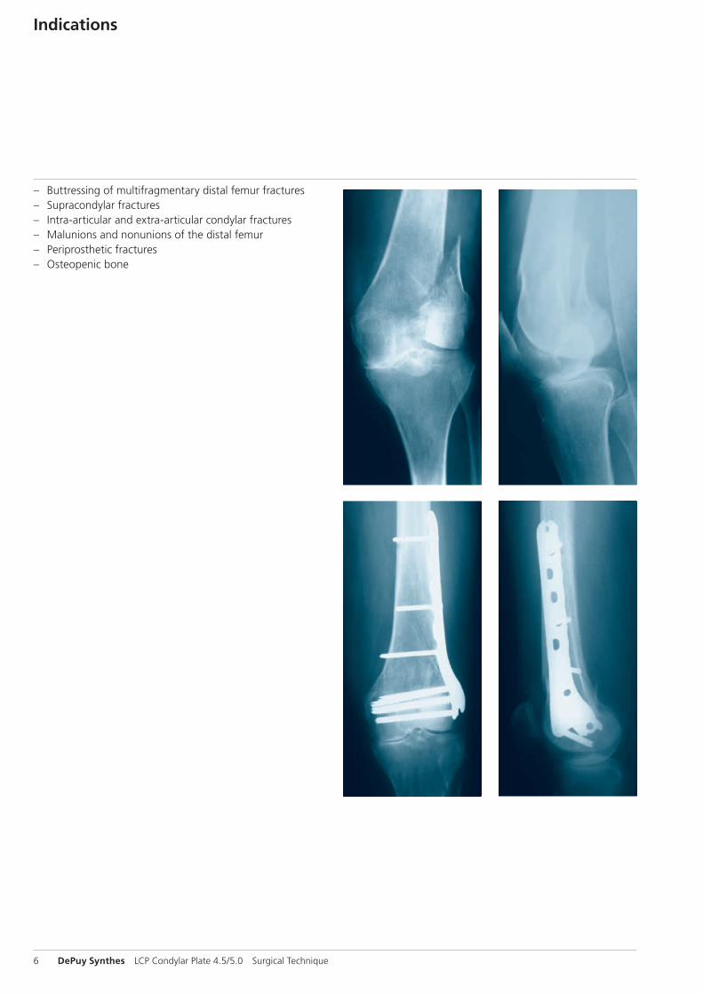
– Buttressing of multifragmentary distal femur fractures – Supracondylar fractures – Intra-articular and extra-articular condylar fractures – Malunions and nonunions of the distal femur – Periprosthetic fractures – Osteopenic bone

LCP Condylar Plate 4.5/5.0 Surgical Technique DePuy Synthes 7
Surgical Technique
1Preparation
Required sets
LCP Condylar Plate Set 4.5/5.0 (stainless steel)
Periarticular LCP Plating System Instrument Set
Cannulated Locking and Cannulated Conical Screw B 5.0 and 7.3 mm Set
LCP Large Fragment Instrument Set
LCP Large Fragment Screw Set
Complete preoperative radiographic assessment and prepare the preoperative plan. Position the patient supine on a radio-lucent operating table. Viewing the distal femur under fluo-roscopy in both the lateral and AP views is necessary.
When using a LCP Condylar Plate Set with the Periarticular LCP Plating System Instrument Set and the Cannulated Lock-ing and Cannulated Conical Screw B 5.0 and 7.3 mm Set, the following sets are also required: the LCP Large Fragment Instrument Set and LCP Large Fragment Screw Set.
X-ray-template for LCP Condylar Plate 4.5/5.0, curved (Art. No. 034.000.482)
8 DePuy Synthes LCP Condylar Plate 4.5/5.0 Surgical Technique
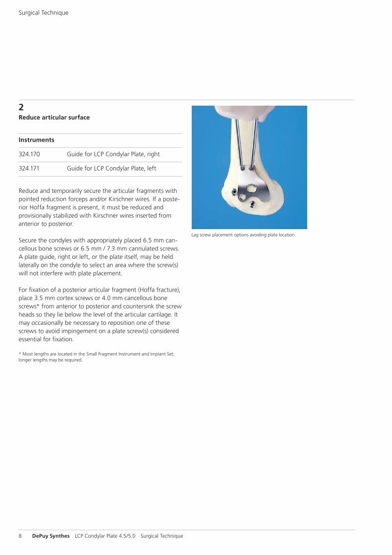
2Reduce articular surface
Instruments
324.170 Guide for LCP Condylar Plate, right
324.171 Guide for LCP Condylar Plate, left
Reduce and temporarily secure the articular fragments with pointed reduction forceps and/or Kirschner wires. If a poste-rior Hoffa fragment is present, it must be reduced and provisionally stabilized with Kirschner wires inserted from anterior to posterior.
Secure the condyles with appropriately placed 6.5 mm can-cellous bone screws or 6.5 mm / 7.3 mm cannulated screws. A plate guide, right or left, or the plate itself, may be held laterally on the condyle to select an area where the screw(s) will not interfere with plate placement.
For fixation of a posterior articular fragment (Hoffa fracture), place 3.5 mm cortex screws or 4.0 mm cancellous bone screws* from anterior to posterior and countersink the screw heads so they lie below the level of the articular cartilage. It may occasionally be necessary to reposition one of these screws to avoid impingement on a plate screw(s) considered essential for fixation.
* Most lengths are located in the Small Fragment Instrument and Implant Set; longer lengths may be required.
Lag screw placement options avoiding plate location.
Surgical Technique
LCP Condylar Plate 4.5/5.0 Surgical Technique DePuy Synthes 9
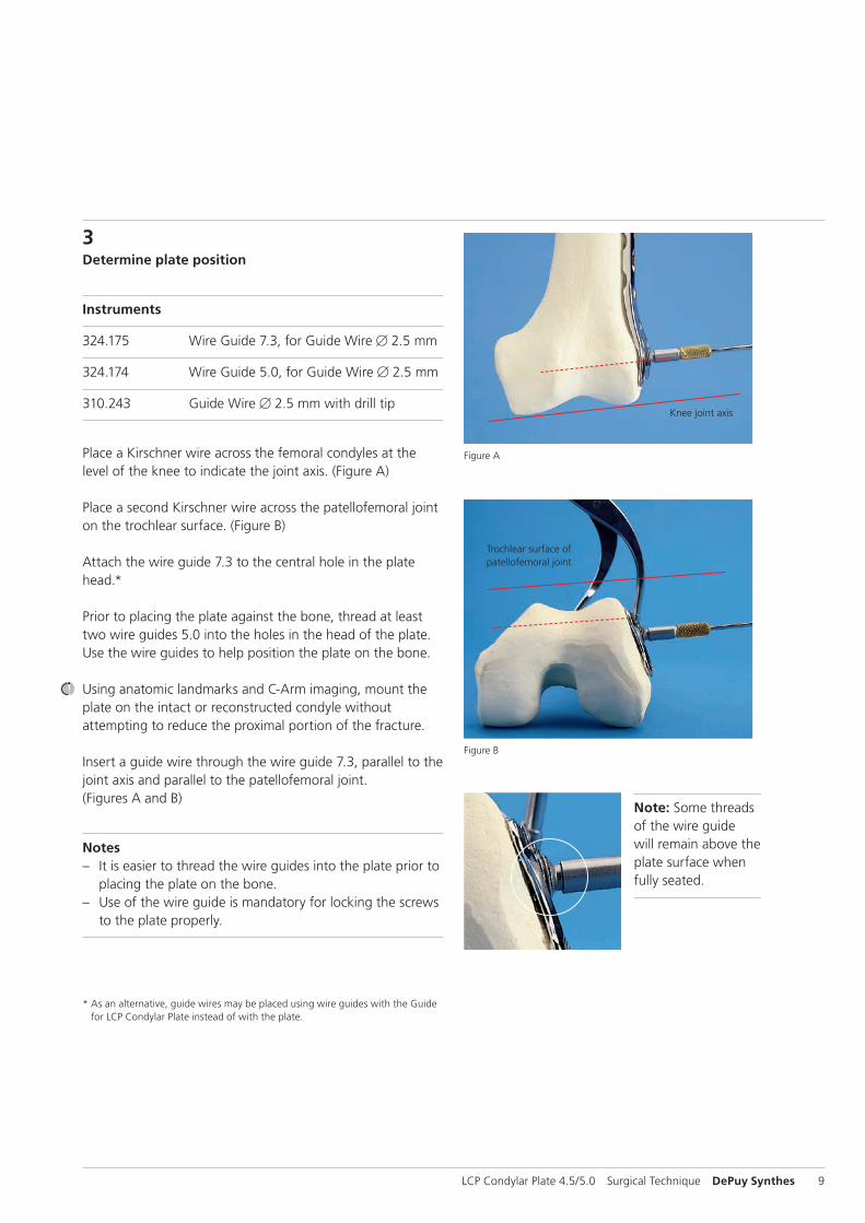
Figure B
Figure A
Knee joint axis
Trochlear surface of patellofemoral joint
* As an alternative, guide wires may be placed using wire guides with the Guide for LCP Condylar Plate instead of with the plate.
3Determine plate position
Instruments
324.175 Wire Guide 7.3, for Guide Wire B 2.5 mm
324.174 Wire Guide 5.0, for Guide Wire B 2.5 mm
310.243 Guide Wire B 2.5 mm with drill tip
Place a Kirschner wire across the femoral condyles at the level of the knee to indicate the joint axis. (Figure A)
Place a second Kirschner wire across the patellofemoral joint on the trochlear surface. (Figure B)
Attach the wire guide 7.3 to the central hole in the plate head.*
Prior to placing the plate against the bone, thread at least two wire guides 5.0 into the holes in the head of the plate. Use the wire guides to help position the plate on the bone.
Using anatomic landmarks and C-Arm imaging, mount the plate on the intact or reconstructed condyle without attempting to reduce the proximal portion of the fracture.
Insert a guide wire through the wire guide 7.3, parallel to the joint axis and parallel to the patellofemoral joint. (Figures A and B)
Notes – It is easier to thread the wire guides into the plate prior to
placing the plate on the bone. – Use of the wire guide is mandatory for locking the screws
to the plate properly.
Note: Some threads of the wire guide will remain above the plate surface when fully seated.
10 DePuy Synthes LCP Condylar Plate 4.5/5.0 Surgical Technique
Surgical Technique
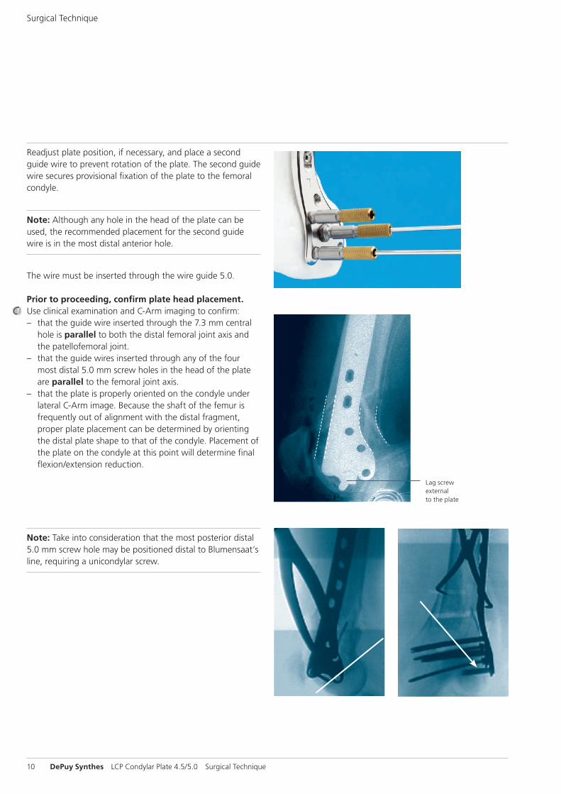
Readjust plate position, if necessary, and place a second guide wire to prevent rotation of the plate. The second guide wire secures provisional fixation of the plate to the femoral condyle.
Note: Although any hole in the head of the plate can be used, the recommended placement for the second guide wire is in the most distal anterior hole.
The wire must be inserted through the wire guide 5.0.
Prior to proceeding, confirm plate head placement.Use clinical examination and C-Arm imaging to confirm: – that the guide wire inserted through the 7.3 mm central
hole is parallel to both the distal femoral joint axis and the patellofemoral joint.
– that the guide wires inserted through any of the four most distal 5.0 mm screw holes in the head of the plate are parallel to the femoral joint axis.
– that the plate is properly oriented on the condyle under lateral C-Arm image. Because the shaft of the femur is frequently out of alignment with the distal fragment, proper plate placement can be determined by orienting the distal plate shape to that of the condyle. Placement of the plate on the condyle at this point will determine final flexion/extension reduction.
Lag screw external to the plate
Note: Take into consideration that the most posterior distal 5.0 mm screw hole may be positioned distal to Blumensaat’s line, requiring a unicondylar screw.

319.701
LCP Condylar Plate 4.5/5.0 Surgical Technique DePuy Synthes 11
4Insert screws (7.3 mm and 5.0 mm)
Instruments
319.701 Measuring Device
314.050 Screwdriver, hexagonal, cannulated
For predrilling in dense bone
310.632 Drill Bit B 5.0 mm, cannulated
310.634 Drill Bit B 4.3 mm, cannulated
Secure the plate position on the lateral femoral condyle with at least 3 guide wires prior to inserting the first screw. Although screws may be inserted in any order, it is usually advantageous to start with the central 7.3 mm screw.
Advance the guide wire until it reaches the medial wall of the femoral condyle. Measure for screw length using the measuring device. For proper screw length measurement, the measuring device must contact the end of the wire guide. This will place the tip of the screw at the tip of the guide wire.
Technique tip: The self-drilling, self-tapping flutes of the 7.3 mm and 5.0 mm screws make predrilling and pretapping unnecessary in most cases. In dense bone, the lateral cortex can be predrilled, if necessary. – Use the 5.0 mm drill bit for 7.3 mm screws. – Use the 4.3 mm drill bit for 5.0 mm screws.

314.050
12 DePuy Synthes LCP Condylar Plate 4.5/5.0 Surgical Technique
Surgical Technique
Remove the wire guide and insert the appropriate length screw over the guide wire and into the bone using the screwdriver. Locking screws may be inserted using power equipment. However, do not use power to seat these screws since this may cause screws to cross-thread in the plate holes.
Securely tighten all locking screws to lock them to the plate.
Notes – If required, lag screw reduction of a fragment must be
accomplished prior to inserting locking screws into the fragment.
– If the plate shifts during screw insertion, the guide wires must be removed and reinserted for the screws to lock to the plate properly.
– To compress the plate to the lateral femoral condyle, it is necessary to utilize a conical screw prior to any locking screws. Conical screws may be replaced with locking screws after reduction is complete.
Note: Some threads of the 7.3 mm cannulated locking screw will remain above the plate surface when fully seated.
LCP Condylar Plate 4.5/5.0 Surgical Technique DePuy Synthes 13
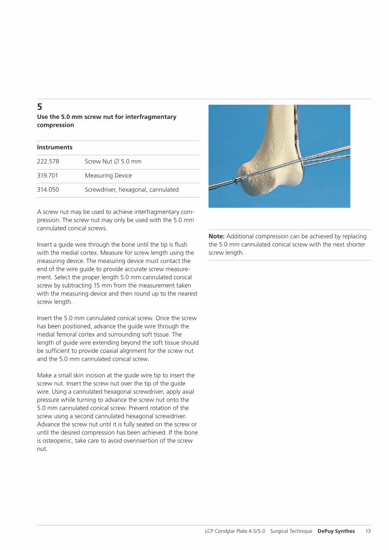
5Use the 5.0 mm screw nut for interfragmentary compression
Instruments
222.578 Screw Nut B 5.0 mm
319.701 Measuring Device
314.050 Screwdriver, hexagonal, cannulated
A screw nut may be used to achieve interfragmentary com-pression. The screw nut may only be used with the 5.0 mm cannulated conical screws.
Insert a guide wire through the bone until the tip is flush with the medial cortex. Measure for screw length using the measuring device. The measuring device must contact the end of the wire guide to provide accurate screw measure-ment. Select the proper length 5.0 mm cannulated conical screw by subtracting 15 mm from the measurement taken with the measuring device and then round up to the nearest screw length.
Insert the 5.0 mm cannulated conical screw. Once the screw has been positioned, advance the guide wire through the medial femoral cortex and surrounding soft tissue. The length of guide wire extending beyond the soft tissue should be sufficient to provide coaxial alignment for the screw nut and the 5.0 mm cannulated conical screw.
Make a small skin incision at the guide wire tip to insert the screw nut. Insert the screw nut over the tip of the guide wire. Using a cannulated hexagonal screwdriver, apply axial pressure while turning to advance the screw nut onto the 5.0 mm cannulated conical screw. Prevent rotation of the screw using a second cannulated hexagonal screwdriver. Advance the screw nut until it is fully seated on the screw or until the desired compression has been achieved. If the bone is osteopenic, take care to avoid over insertion of the screw nut.
Note: Additional compression can be achieved by replacing the 5.0 mm cannulated conical screw with the next shorter screw length.
14 DePuy Synthes LCP Condylar Plate 4.5/5.0 Surgical Technique
Surgical Technique
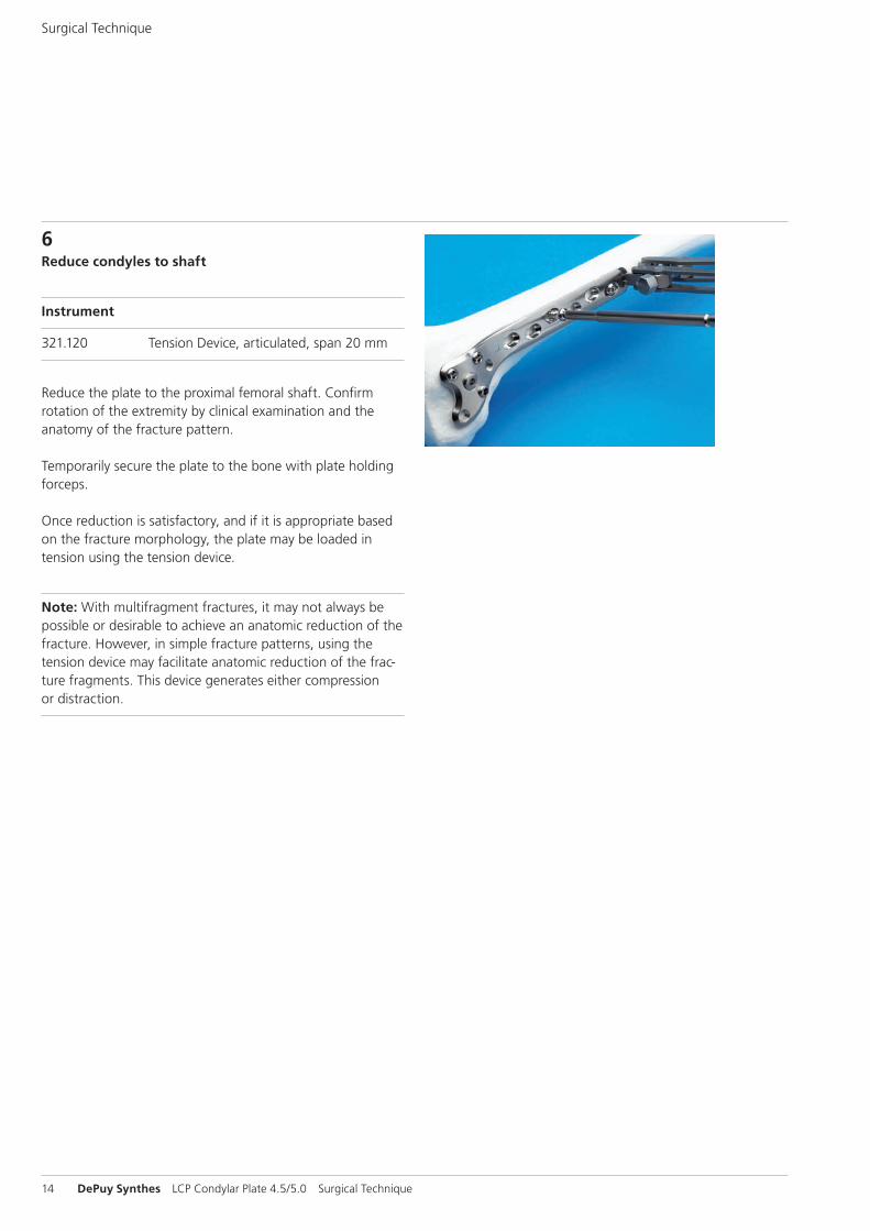
6Reduce condyles to shaft
Instrument
321.120 Tension Device, articulated, span 20 mm
Reduce the plate to the proximal femoral shaft. Confirm rotation of the extremity by clinical examination and the anatomy of the fracture pattern.
Temporarily secure the plate to the bone with plate holding forceps.
Once reduction is satisfactory, and if it is appropriate based on the fracture morphology, the plate may be loaded in tension using the tension device.
Note: With multifragment fractures, it may not always be possible or desirable to achieve an anatomic reduction of the fracture. However, in simple fracture patterns, using the tension device may facilitate anatomic reduction of the frac-ture fragments. This device generates either compression or distraction.
1 1
2
1 1
2
LCP Condylar Plate 4.5/5.0 Surgical Technique DePuy Synthes 15
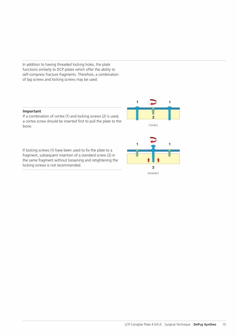
Important If a combination of cortex (1) and locking screws (2) is used, a cortex screw should be inserted first to pull the plate to the bone.
If locking screws (1) have been used to fix the plate to a fragment, subsequent insertion of a standard screw (2) in the same fragment without loosening and retightening the locking screws is not recommended.
Correct
Incorrect
In addition to having threaded locking holes, the plate func tions similarly to DCP plates which offer the ability to self-compress fracture fragments. Therefore, a combination of lag screws and locking screws may be used.
16 DePuy Synthes LCP Condylar Plate 4.5/5.0 Surgical Technique
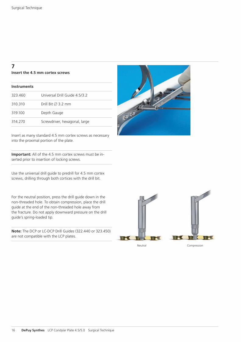
7Insert the 4.5 mm cortex screws
Instruments
323.460 Universal Drill Guide 4.5/3.2
310.310 Drill Bit B 3.2 mm
319.100 Depth Gauge
314.270 Screwdriver, hexagonal, large
Insert as many standard 4.5 mm cortex screws as necessary into the proximal portion of the plate.
Important: All of the 4.5 mm cortex screws must be in-serted prior to insertion of locking screws.
Use the universal drill guide to predrill for 4.5 mm cortex screws, drilling through both cortices with the drill bit.
Neutral Compression
For the neutral position, press the drill guide down in the non-threaded hole. To obtain compression, place the drill guide at the end of the non-threaded hole away from the fracture. Do not apply downward pressure on the drill guide’s spring-loaded tip.
Note: The DCP or LC-DCP Drill Guides (322.440 or 323.450) are not compatible with the LCP plates.
Surgical Technique
LCP Condylar Plate 4.5/5.0 Surgical Technique DePuy Synthes 17
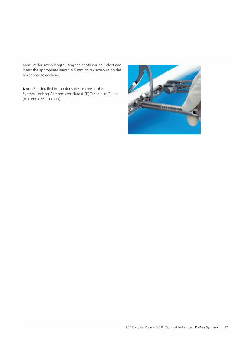
Measure for screw length using the depth gauge. Select and insert the appropriate length 4.5 mm cortex screw using the hexagonal screwdriver.
Note: For detailed instructions please consult the Synthes Locking Compression Plate (LCP) Technique Guide (Art. No. 036.000.019).
18 DePuy Synthes LCP Condylar Plate 4.5/5.0 Surgical Technique
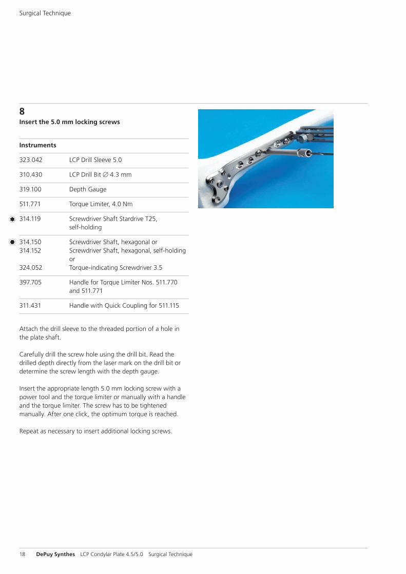
8Insert the 5.0 mm locking screws
Instruments
323.042 LCP Drill Sleeve 5.0
310.430 LCP Drill Bit B 4.3 mm
319.100 Depth Gauge
511.771 Torque Limiter, 4.0 Nm
314.119 Screwdriver Shaft Stardrive T25, self-holding
314.150 Screwdriver Shaft, hexagonal or314.152 Screwdriver Shaft, hexagonal, self-holding or 324.052 Torque-indicating Screwdriver 3.5
397.705 Handle for Torque Limiter Nos. 511.770 and 511.771
311.431 Handle with Quick Coupling for 511.115
Attach the drill sleeve to the threaded portion of a hole in the plate shaft.
Carefully drill the screw hole using the drill bit. Read the drilled depth directly from the laser mark on the drill bit or determine the screw length with the depth gauge.
Insert the appropriate length 5.0 mm locking screw with a power tool and the torque limiter or manually with a handle and the torque limiter. The screw has to be tightened manually. After one click, the optimum torque is reached.
Repeat as necessary to insert additional locking screws.
Surgical Technique
LCP Condylar Plate 4.5/5.0 Surgical Technique DePuy Synthes 19
Notes – Use of the drill guide is mandatory for screws to lock
to the plate properly. – For detailed instructions please consult the Synthes
Locking Compression Plate (LCP) Technique Guide (Art. No. 036.000.019).
Examine the limb clinically and radiographically. It is impor-tant that the femoral condyles are oriented properly to the femoral shaft.
Securely tighten all distal locking screws again prior to closing.
20 DePuy Synthes LCP Condylar Plate 4.5/5.0 Surgical Technique
Cleaning tip
Instrument
319.461 Cleaning Stylet B 2.5 mm, for Cannulated Instruments
Cleaning the cannulation in each instrument is imperative for proper function. Instruments should be cleared intraopera-tively using the cleaning stylet to prevent accumulation of debris in the cannulation and potential binding of the instru-ments about the guide wire.
Surgical Technique
LCP Condylar Plate 4.5/5.0 Surgical Technique DePuy Synthes 21
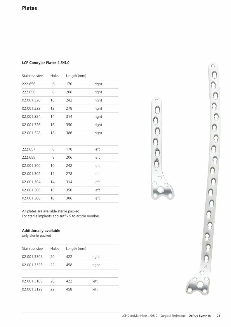
Plates
LCP Condylar Plates 4.5/5.0
Stainless steel Holes Length (mm)
222.656 6 170 right
222.658 8 206 right
02.001.320 10 242 right
02.001.322 12 278 right
02.001.324 14 314 right
02.001.326 16 350 right
02.001.328 18 386 right
222.657 6 170 left
222.659 8 206 left
02.001.300 10 242 left
02.001.302 12 278 left
02.001.304 14 314 left
02.001.306 16 350 left
02.001.308 18 386 left
All plates are available sterile packed. For sterile implants add suffix S to article number.
Additionally availableonly sterile packed
Stainless steel Holes Length (mm)
02.001.330S 20 422 right
02.001.332S 22 458 right
02.001.310S 20 422 left
02.001.312S 22 458 left
22 DePuy Synthes LCP Condylar Plate 4.5/5.0 Surgical Technique
Screws
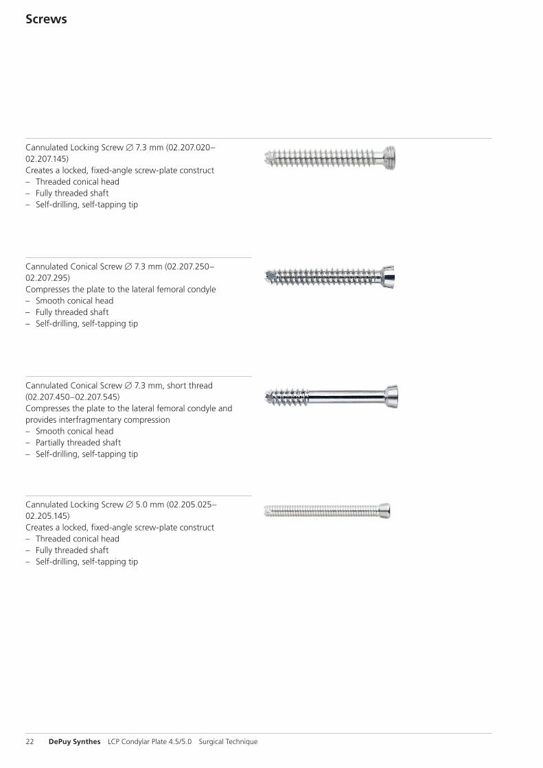
Cannulated Locking Screw B 7.3 mm (02.207.020–02.207.145) Creates a locked, fixed-angle screw-plate construct – Threaded conical head – Fully threaded shaft – Self-drilling, self-tapping tip
Cannulated Conical Screw B 7.3 mm, short thread (02.207.450–02.207.545) Compresses the plate to the lateral femoral condyle and provides interfragmentary compression – Smooth conical head – Partially threaded shaft – Self-drilling, self-tapping tip
Cannulated Conical Screw B 7.3 mm (02.207.250–02.207.295) Compresses the plate to the lateral femoral condyle – Smooth conical head – Fully threaded shaft – Self-drilling, self-tapping tip
Cannulated Locking Screw B 5.0 mm (02.205.025–02.205.145)Creates a locked, fixed-angle screw-plate construct – Threaded conical head – Fully threaded shaft – Self-drilling, self-tapping tip
LCP Condylar Plate 4.5/5.0 Surgical Technique DePuy Synthes 23
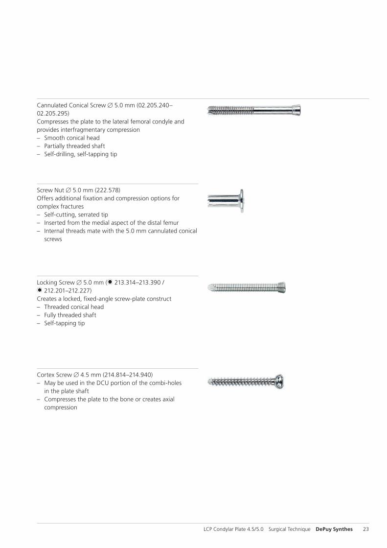
Screw Nut B 5.0 mm (222.578)Offers additional fixation and compression options for complex fractures – Self-cutting, serrated tip – Inserted from the medial aspect of the distal femur – Internal threads mate with the 5.0 mm cannulated conical
screws
Locking Screw B 5.0 mm ( 213.314–213.390 / 212.201–212.227)
Creates a locked, fixed-angle screw-plate construct – Threaded conical head – Fully threaded shaft – Self-tapping tip
Cortex Screw B 4.5 mm (214.814–214.940) – May be used in the DCU portion of the combi-holes
in the plate shaft – Compresses the plate to the bone or creates axial
compression
Cannulated Conical Screw B 5.0 mm (02.205.240– 02.205.295)Compresses the plate to the lateral femoral condyle and provides interfragmentary compression – Smooth conical head – Partially threaded shaft – Self-drilling, self-tapping tip
24 DePuy Synthes LCP Condylar Plate 4.5/5.0 Surgical Technique
Drill and Wire Guides
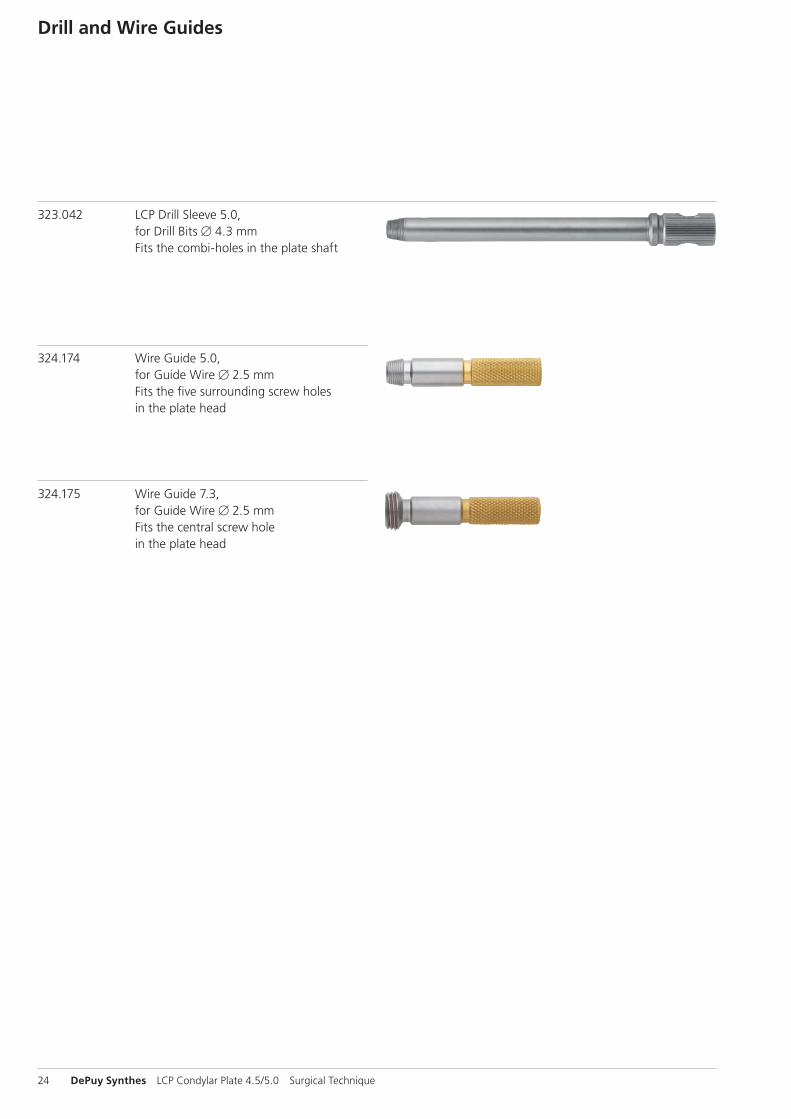
324.175 Wire Guide 7.3, for Guide Wire B 2.5 mm Fits the central screw hole in the plate head
324.174 Wire Guide 5.0, for Guide Wire B 2.5 mm Fits the five surrounding screw holes in the plate head
323.042 LCP Drill Sleeve 5.0, for Drill Bits B 4.3 mm Fits the combi-holes in the plate shaft
324.174
324.175
323.042
LCP Condylar Plate 4.5/5.0 Surgical Technique DePuy Synthes 25
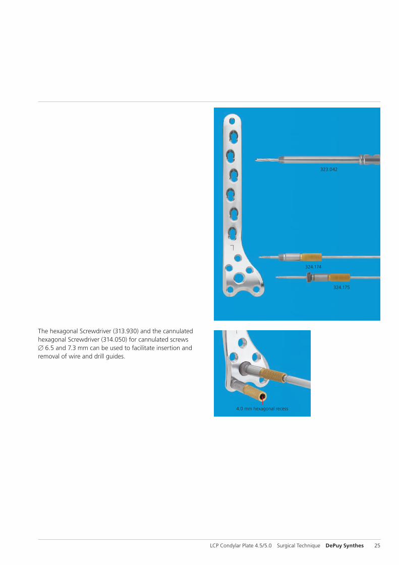
The hexagonal Screwdriver (313.930) and the cannulated hexagonal Screwdriver (314.050) for cannulated screws B 6.5 and 7.3 mm can be used to facilitate insertion and removal of wire and drill guides.
4.0 mm hexagonal recess

26 DePuy Synthes LCP Condylar Plate 4.5/5.0 Surgical Technique
Sets
01.120.021 Periarticular Instruments
68.120.447 Vario Case
68.120.445 Insert
01.120.022 Cannulated Conical and Cannulated Locking Screws B 7.3 and 5.0 mm (stainless steel)
68.120.450 Sterilizing Tray
Additionally required – LCP Large Fragment Instrument Set – LCP Large Fragment Screw Set
LCP Condylar Plate 4.5/5.0 Surgical Technique DePuy Synthes 27
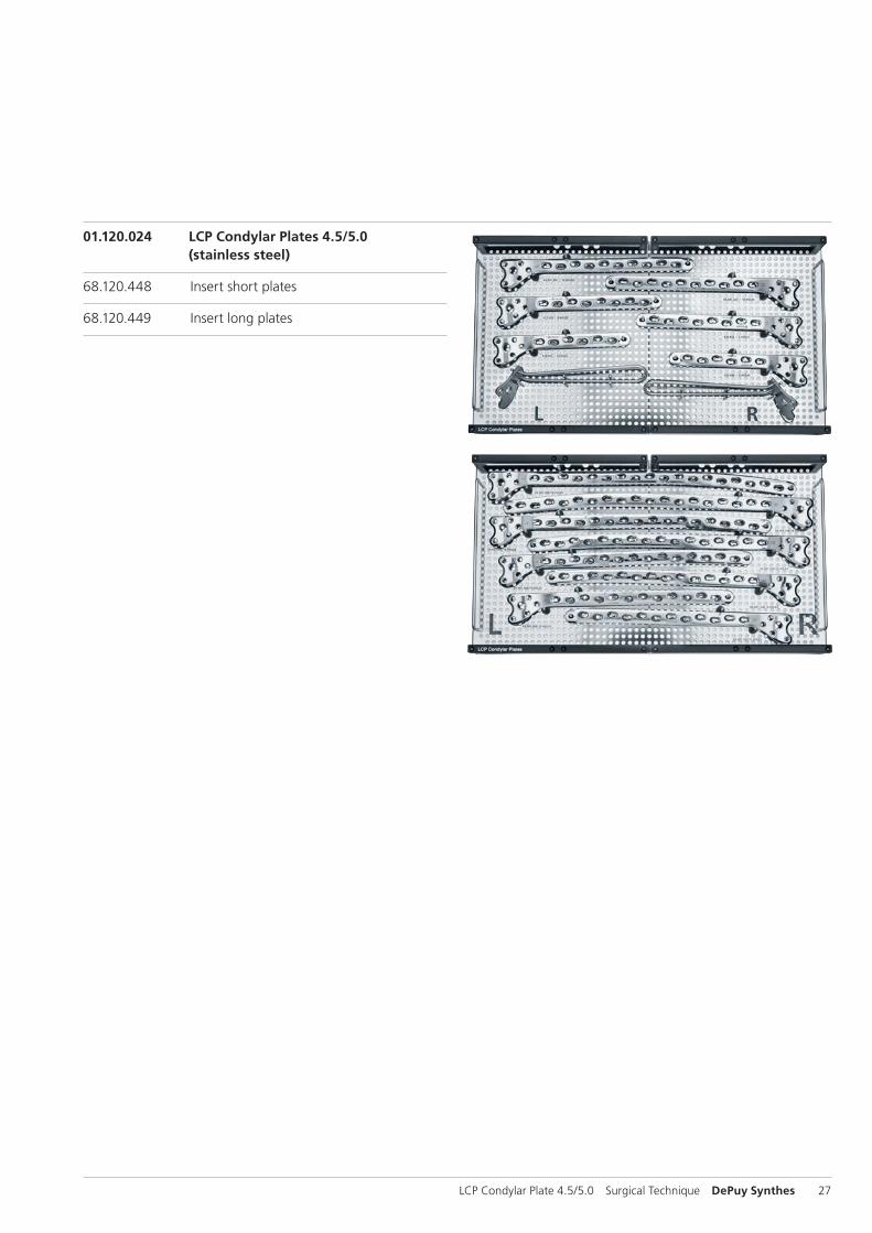
01.120.024 LCP Condylar Plates 4.5/5.0 (stainless steel)
68.120.448 Insert short plates
68.120.449 Insert long plates
28 DePuy Synthes LCP Condylar Plate 4.5/5.0 Surgical Technique
MRI Information
Torque, Displacement and Image Artifacts according to ASTM F 2213-06, ASTM F 2052-06e1 and ASTM F2119-07Non-clinical testing of worst case scenario in a 3 T MRI system did not reveal any relevant torque or displacement of the construct for an experimentally measured local spatial gradient of the magnetic field of 3.69 T/m. The largest image artifact extended approximately 169 mm from the construct when scanned using the Gradient Echo (GE). Testing was conducted on a 3 T MRI system.
Radio-Frequency-(RF-)induced heating according to ASTM F2182-11aNon-clinical electromagnetic and thermal testing of worst case scenario lead to peak temperature rise of 9.5 °C with an average temperature rise of 6.6 °C (1.5 T) and a peak temperature rise of 5.9 °C (3 T) under MRI Conditions using RF Coils [whole body averaged specific absorption rate (SAR) of 2 W/kg for 6 minutes (1.5 T) and for 15 minutes (3 T)].
Precautions: The above mentioned test relies on non-clini-cal testing. The actual temperature rise in the patient will depend on a variety of factors beyond the SAR and time of RF application. Thus, it is recommended to pay particular attention to the following points: – It is recommended to thoroughly monitor patients under-
going MR scanning for perceived temperature and/or pain sensations.
– Patients with impaired thermo regulation or temperature sensation should be excluded from MR scanning proce-dures.
– Generally it is recommended to use a MR system with low field strength in the presence of conductive implants. The employed specific absorption rate (SAR) should be reduced as far as possible.
– Using the ventilation system may further contribute to reduce temperature increase in the body.


0123
Synthes GmbHEimattstrasse 34436 OberdorfSwitzerlandTel: +41 61 965 61 11Fax: +41 61 965 66 00www.depuysynthes.com
This publication is not intended for distribution in the USA.
All surgical techniques are available as PDF files at www.depuysynthes.com/ifu ©
DeP
uy S
ynth
es T
raum
a, a
div
isio
n of
Syn
thes
Gm
bH. 2
015.
A
ll rig
hts
rese
rved
. 03
6.0
00.
727
DSE
M/T
RM
/071
4/01
25(1
) 09
/15